

Page 1
Code 62456585 Rev: 07/2005
Page 2
Technical data 3 - 4 Technische Beschreibung
Burner selection 5 Merkmale der Brenner
Installation 6 Installation - Montage
Water connection 7 Hydraulischer Anschluss
Electrical connection 8 Elektrischer Anschluss
Casing assembly 9 – 10 – 11 -12 Montage der Ummantelung
Specification sheet 13 Beschreibung für das Leistungsverzeichnis
Commissioning and Servicing instructions 14 Inbetriebnahme - Instandhaltung
Boiler spare parts list 15 - 16 Ersatzteilliste - Kessel
2
Manufactured by
ACV – Manufacturing
B 7180 Seneffe
ACV reserves the right to change the technical characteristics
and specification of its products without notice
ACV behält sich das Recht vor, die technischen Eigenschaften und
die Ausrüstung seiner Geräte ohne vorherige Mitteilung zu ändern
Page 3
g
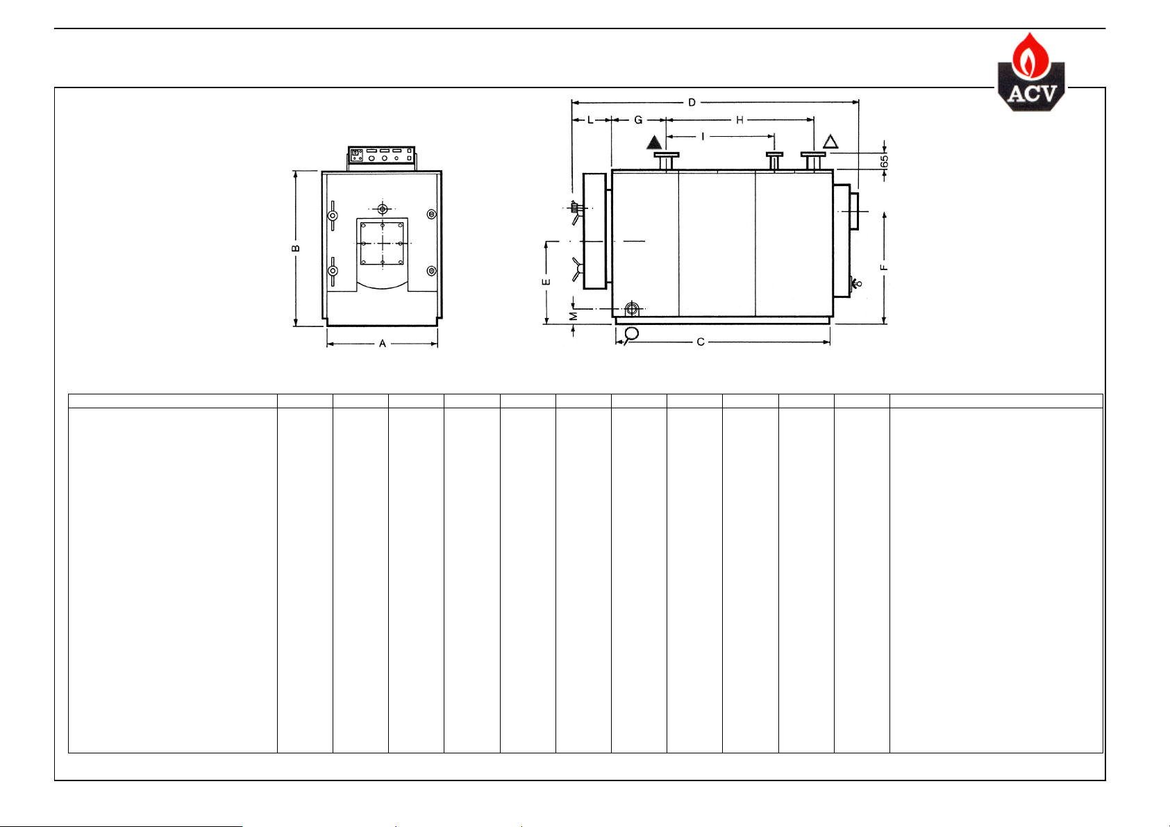
TECHNICAL DATA –TECHNISCHE MERKMALE
Maximum operating temperature: 110 °C
Maximum working pressure: 6 bar (EN 303)
Width of casin
TYPE COMPACT A CA 250 CA 300 CA 350 CA 400 CA 500 CA 600 CA 700 CA 800 CA 900 CA 1000 CA 1250
Code 4120401 4120501 4120601 4120701 4120801 4120901 4121001 4121101 4121201 4121301 4611901
Fuel Type Gas/Fuel-Öl Gas/Fuel-Öl Gas/Fuel-Öl Gas/Fuel-Öl Gas/Fuel-Öl Gas/Fuel-Öl Gas/Fuel-Öl Gas/Fuel-Öl Gas/Fuel-Öl Gas/Fuel-Öl Gas/Fuel-Öl typ
Input KW 324/343 381/419 444/482 507/559 635/698 769/824 886/962 1014/1104 1141/1243 1267/1393 1593 kW
Rated output KW 291/314 349/384 407/442 465/512 582/640 698/756 814/884 930/1012 1047/1140 1163/1279 1453 kW
Combustion efficiency % 91,5 91,6 91,6 91,65 91,7 91,7 91,85 91,7 91,75 91,8 92,1 %
Maintenance loss at 60°C as % of
rated value % 0,192 0,192 0,192 0,192 0,192 0,153 0,153 0,153 0,153 0,063 0,1 %
Water pressure drop mbar 22/26 28/34 37/44 23/28 35/42 30/36 33/39 40/48 47/56 50/60 60 mbar
Pressure drop, flue mbar 3,2/3,8 3,6/4,3 4/4,8 4,3/5,2 5,3/5,8 5,6/6,7 5,9/7,1 6,4/7,7 6,8/8,2 7,1/8,4 7,8 mbar
Mass rate of combustion products
Total capacity L 350 400 470 630 650 800 890 920 1030 1140 1240 L
Primary connection (T3 – T4) Flange DN 80 DN 80 DN 80 DN 100 DN 100 DN 100 DN 100 DN 125 DN 125 DN 125 DN 125 Ø Flansch
Chimney (T1)connection O.D. Ø mm 240 240 240 300 300 350 350 450 450 450 450 mm
Dimensions (mm) A 890 890 890 1100 1100 1200 1200 1300 1300 1300 1300 A
B 1095 1095 1095 1300 1300 1455 1455 1555 1555 1555 1555 B
C 1250 1400 1500 1660 1740 1760 1840 1840 2090 2350 2490 C
D 1730 1880 1980 2190 2270 2290 2370 2370 2620 2880 3020 D
E 560 560 560 680 680 760 760 800 800 800 800 E
F 790 790 790 930 930 1020 1020 1110 1110 1110 1110 F
G 450 450 450 465 465 465 465 465 465 465 465 G
H 580 730 830 970 1050 1070 1150 1150 1400 1660 1810 H
I 330 480 580 650 730 750 830 830 1080 1340 1490 I
L 250 250 250 270 270 270 270 270 270 270 270 L
M 110 110 110 130 130 140 140 145 145 145 145 M
Empty weight Kg 710 770 830 1075 1185 1465 1570 1570 1945 2100 2200 Kg
: add 70 mm to the dimension "A"
Gas Kg/sec 0,16 0,2 0,22 0,23 0,32 0,39 0,45 0,5 0,55 0,62 0,77 Kg/sec
Oil Kg/sec 0,15 0,2 0,21 0,25 0,3 0,35 0,44 0,52 0,55 0,6 0,76 Kg/sec
Maximale Betriebstemperatur: 110 °C
Betriebsdruck: 6 bar (EN 303)
Breite incl. Ummantelung: Masse unter "A" + 70 mm
TYP COMPACT A
Code
Vor- und Rücklauf Heizung T3-T4
Kaminanschluss (T1 Aussen Φ)
Brennstoff
Leistungsaufnahme
Nennleistung
Verbrennungsertrag
Hitzeverlust bei 60°C, in % von
Nennleistung
Druckverlust im Wasser
Brennkammerdruck
Abgasmassen
Gas
öl
Wasserinhalt
Abmessungen (mm)
Leergewicht
3
Page 4
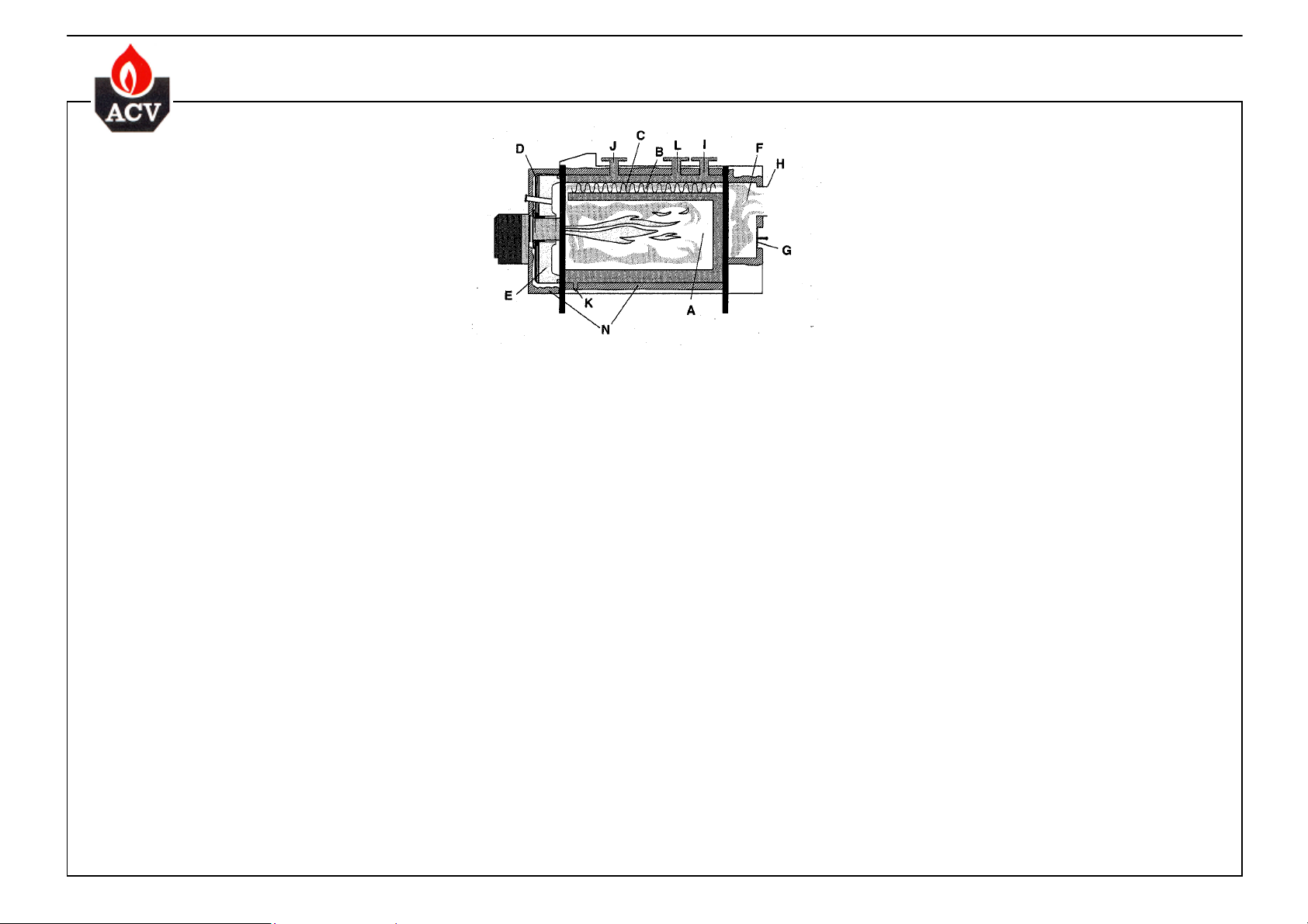
TECHNICAL DATA –TECHNISCHE BESCHREIBUNG
A = water cooled combustion chamber
B = firetubes
C = turbulators
D = combustion chamber door
E = door insulation
F = smokehood
G = cleanout cover
Boiler body
Water cooled combustion chamber constructed from
carbon steel ST 37/2 plates, with a thickness per DIN
4702 Pt 1. Pressurised combustion chamber and fire
tubes, the latter fitted with removable turbulators.
After welding, the boiler body is hydrotested at 7.5
bars.
Combustion chamber
The combustion chamber is free to expand and is
constructed in accordance with the requirements of
DIN 4702.
The thickness of the plates is:
type 250-350: 6 mm,
type 400-500: 7 mm
type 600-1250: 8 mm.
Fire tubes
The fire tubes protrude 10 mm through the rear tube
plate. This ensures "overheating" of the ends of the
tubes and the evaporation of any condensation
forming there.
Water circulation
The return water is directed onto the front tube plate
by a baffle.
The lower part of the boiler does not contain firetubes to avoid potential sludge deposits, reducing the
heat transfer.
Combustion chamber door
The combustion chamber door opens right or left as
required by site conditions.
A ceramic fibre brick laid down on a rockwool screen
provides a good insulation. Tightening the door
against a ceramic fibre gasket using four M 12 nuts
ensures gas tightness.
Smoke hood
The removable smoke hood is manufactured in 3 mm
steel and fixed by six M10 bolts. The lower part of the
smoke hood has a cleanout cover Ø150 mm.
H = chimney connection
I = flow connection
J = return connection
K = drain cock
L = safety valve tapping
N = glasswool insulation
Casing
The all-metal casing is degreased and phosphated
before coating.
The epoxy-polyester coating is heated up to 200°C,
which ensures a high quality finish and guarantees a
long life.
Insulation
The COMPACT A range of boilers have a double
insulation:
• approximately 100 mm thickness of glass wool on
the boiler body
• approximately 25 mm of aluminium faced glass
wool in the casing panels.
Safety
The COMPACT A range of boilers are fitted with a
safety switch to prevent firing if the combustion
chamber door is not correctly closed.
A manual reset limit thermostat factory preset at
103°C prevents overheating.
Packing
The boiler is delivered on a wooden base with in the
furnace of the boiler the control panel, the turbulators
and the insulation for the boiler body. The complete
casing is packed in a wooden box.
Standard controls
• Thermometer
• Control thermostat first and second stage
• Manual reset limit thermostat
• On/Off switch
• Electric plug
• Warning light door closure
• Indicator light 1
st
and 2nd stage
• Fitting for hour run meter
A = Wassergekühlte Brennkammer
B = Rauchgaszüge
C = Turbulatoren
D = Brennkammertür
E = Türisolierung
F = Rauchgassammelkasten
G = Reinigungsöffnung
Kesselkörper
Heizkessel aus Stahl ST 37/2 nach DIN 4702 Teil1
konstruiert und mit wassergekühlter
Unterdruckbrennkammer ausgestattet.
Die Rauchgaskanale sind mit demontierbaren
Turbulatoren ausgestattet.
Der Kesselkörper wird nach der Montage mit 7,5 bar
hydraulisch geprüft.
Brennkammer
Brennkammer nach DIN 4702 aus massivem Stahl von
6 mm Starke (bei den Ausführungen 250-350),
7 mm Starke (bei den Ausführungen 400-500) oder
8 mm Starke (bei den Ausführungen 600-1250).
Rauchgaskanale
Die Rauchgaszüge ragen 10 mm aus der
Brennkammer heraus, um jegliche Kondensation zu
verhindern. Die Endstücke der Züge werden so- mit
zusätzlich erhitzt und eventuell entstehendes
Kondenswasserverdampft.
Wasserzirkulation
Das Rücklaufwasser wird durch ein eingebautes
Zirkulationssystem in den vorderen Bereich des
Kessels geleitet. Auf Verrohrungen im unteren Bereich
wurde gezielt verzichtet, damit keinerlei Ablagerungen
die Wärmeübertragung behindern.
Brennkammertür
Massive Brennkammertür mit rechtem oder linkem
Türanschlag.
Isolierung durch einen keramischen Türstein, der auf
eine Isolierschicht aus Mineralwolle aufgebracht wird.
Schließlich wird noch eine Dichtung aus Keramikfaser
montiert und mit 4 Muttern M 12 befestigt.
Rauchgassammelkasten
Demontierbarer Rauchgassammelkasten BUS 3 mm
starkem Stahl, die Befestigung ist durch 6
H = Kaminanschluss
I = Heizungsvorlauf
J = Heizungsrücklauf
K = Entleerung
L = Anschluss Sicherheitsventil
N = Isolierung aus Glaswolle
Bolzen M 10 gesichert.
Der Rauchgassammelkasten weist im unteren Bereich eine Reinigungsöffnung Ø150 mm auf.
Ummantelung
Die Ummantelung BUS Stahlblech wird vor dem
lackieren entfettet und phosphatiert. Anschließend
erfolgt die Einbrennlackierung bei 200°C - Garantie für
lange Lebensdauer und erstklassige Verarbeitung.
Epoxy-Polyester Schutz.
Isolierung
Der COMPACT A ist doppelt isoliert;
• eine Glaswollschicht von 100 mm wird direkt auf den
Kesselkörper aufgebracht.
• eine weitere Schicht von 25 mm Glaswolle mit
Aluminiumbeschichtung isoliert die Ummantelung.
Sicherheit
.Der COMPACT A ist mit einem Sicherheitssystem
ausgerüstet. welches eine Sicherheitsabschaltung bei
geöffneter Brennkammertür vornimmt.
.Der manuell wiedereinschaltbare
Sicherheitsthermostat verhindert jegliche Überhitzung
Einstelltemperatur: 103°C.
Verpackung
Der Kessel wird auf einer Holzpalette geliefert.
Schaltfeld. Turbulatoren und Mineralfasermatten für die
Isolierung des Kesselkörpers befinden sich im
Brennkammer. Die Ummantelung ist für den Transport
durch ein Holzbehaltnis geschützt.
Basisregelung
• Thermometer
• Regelthermostat -1. und 2. Betriebsstufe
• Sicherheitsthermostat -manuell wiedereinschaltbar
• Hauptschalter
• Steckdose
• Kontrollleuchte -Tür
• Kontrollleuchte -1. und 2. Betriebsstufe.
• Môglichkeit zum Einbau des Betriebsstundenzahlers.
4
Page 5
gung
BURNER SELECTION –BESCHREIBUNG DES BRENNERS
The boiler is approved according to EN 303.
Therefore, it can be combined with burners conform to EN 267 for fueloil, or EN 676 for gas.
Contact your local ACV distributor for more information.
IMPORTANT: the burnerhead must meet all the requirements below:
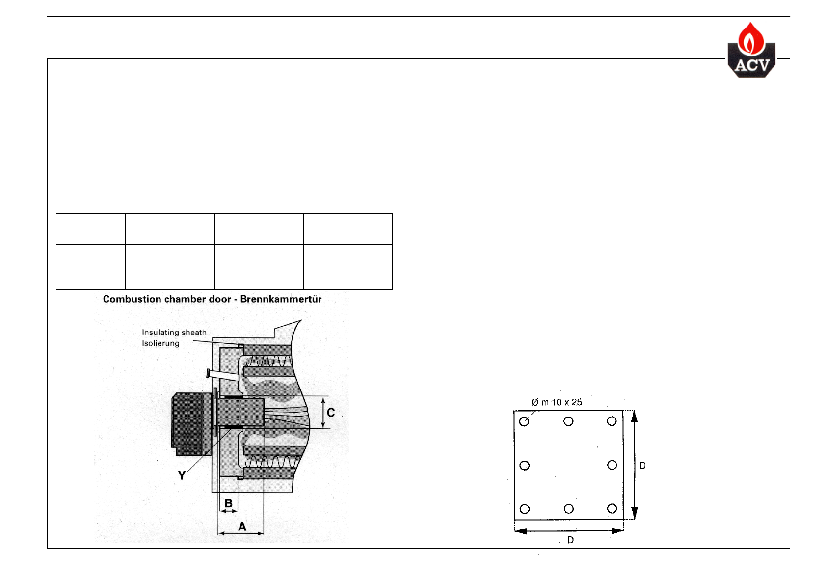
Boiler – Kessel
Type CA
250 - 350 345 300 245 190 185 350
400 - 500 375 325 245 200 205 350
600 - 700 425 370 320 250 240 450
800 - 1250 425 370 320 250 265 450
A
(mm)
Gaz (s)
A (mm)
Fuel-öl
A(mm)
Heavy fuel
Schweröl
B
(mm) C (mm)
D
(mm)
Die CA-Kessel is zugelassen nach EN 303.
Der Kessel kann deshalb kombiniert werden mit Brenner zugelassen nach EN 267 (Heizöl) oder
EN 676 (Gas).
Bitte nehmen Sie kontakt auf mit ihren ACV-Vertretung für weitere Informationen.
WICHTIG: Der Brenner unterstehende Forderungen erfüllen:
Important:
It is necessary to insulate
the burnermouth with
the insulating sheat – see ref. Y.
Aufgepaßt:
Es ist unentbehrlich das Brennerrohr mit der zu
diesem Zweck vorgesehen Isolierung zu
isolieren (siehe Y)
Burner mounting flanges
Befesti
sflansch des Brenners
5
Page 6

INSTALLATION - MONTAGE
Boiler room
IMPORTANT: The boiler must be installed by a qualified engineer in accordance with the local
standards and codes of practice.
This room must comply with all local regulations in terms of dimensions, fire resistance of walls, steel
doors, flues and high and low ventilation.
It must be large enough to allow good access and the entrance must be large enough to allow entry
and replacement of the boiler body.
Minimum side clearance: 600 mm.
Minimum front clearance: 1250 mm.
Minimum rear clearance: 600 mm.
Minimum top clearance: 1000 mm.
It is imperative that there is adequate low-level ventilation, to allow combustion air to the burner, high
level ventilation and a drain for use during boiler drain-down.
The table below is shown by way of indication only, as regulations may vary from country to country.
Heizungsraum
WICHTIG: Die Installation ist von entsprechend qualifiziertem Fachpersonal in
Übereinstimmung mit den einschlägigen Normen und Vorschriften durchzuführen.
Die örtlich geltenden Normen in Bezug auf Abmessungen, Hitzewiderstand, Stahltüren, Kamin,
sowie Be- und Entlüftung sind zu beachten.
Der Heizungsraum muß geräumig genug sein, um einen leichten Zugang zum Gerat zu
ermöglichen.
Minimaler Seiten abstand: 600 mm.
Minimaler Abstand vorn: 1250 mm.
Minimaler Abstand vorn: 600 mm.
Minimaler Abstand oberhalb: 1000 mm.
Der Heizungsraum muß ausreichend be- und entlüftet werden und mit einem Abfluss für die
Entleerung versehen sein.
Aufgrund der von Land zu Land unterschiedlichen Vorschriften hat die nachstehende Tabelle
lediglich Referenzcharakter.
Details of flue and ventilation requirements Beschreibung von Kamin und Belüftung
Boiler type CA 250 300 350 400 500 600 700 800 900 1000 1250 Kessel CA Typ
Minimum fresh air
intake
m³/h
High level ventilation dm² 3 3 3 3 4 4 4 6 6 6 8 dm² Belüftung
Low level ventilation dm² 18 22 25 30 37 43 50 58 65 73 90 dm² Entlüftung
Single wall flue Herkömmlicher Kamin:
Height 10 m. – Φ min. mm 270 300 330 360 400 430 470 490 520 550 600 mm Höhe 10 m. – Φ min.
Height 15 m. – Φ min. mm 250 270 300 330 360 390 420 450 470 500 550 mm Höhe 15 m. – Φ min.
Height 20 m. – Φ min. mm 240 260 290 310 310 360 390 420 440 470 500 mm Höhe 20 m. – Φ min.
Height 25 m. – Φ min. mm 230 250 270 290 290 350 370 400 420 440 470 mm Höhe 25 m. – Φ min.
Twin wall flue
Height 10 m. – Φ min. mm 230 240 260 270 300 330 350 370 390 410 470 mm Höhe 10 m. – Φ min.
Height 15 m. – Φ min. mm 220 230 250 260 290 310 330 350 370 390 440 mm Höhe 15 m. – Φ min.
Height 20 m. – Φ min. mm 220 230 240 250 280 290 310 330 350 370 420 mm Höhe 20 m. – Φ min.
Height 25 m. – Φ min. mm 210 220 230 240 270 280 300 320 330 350 400 mm Höhe 25 m. – Φ min.
296
363 417 483 604 714 835 956 1077 1210 1500 m³/h Minimale Frischluftzufuhr
Metallkamin mit doppelter
Wandung
The cross sectional area of the flue is calculated from:
S = 5,6 Qc / √H
S in cm² Qc= KW (input) H in m
The metal chimney is designed according DIN 4705
6
Der Durchmesser bei einem herkömmlichen Kamin wird nach formel:
S = 5,6 Qc / √H berechnet.
S in cm² ausgedrückt Qc = KW (Eingang) H = m
Die Abmessungen des Metallkamins werden nach DIN 4705 berechnet.
Page 7

WATER CONNECTION –HYDRAULISCHE ANSCHLÜSSE
With this type of boiler, it is essential to install a primary circulation loop (A) is installed in order to
avoid local overheating of the boiler body and to control the return temperature to the boiler,
which must not fall below 60° C.
A probe mounted in the return water, set at a minimum of 60°C, brings on the heating pumps if
the return water falls to a too Iow temperature.
Die Kessel vom Typ CA müssen mit einem Zirkulationsanschluss am Primarkreislauf (A)
ausgestattet werden, um die Überhitzung einzelner Partien des Kesselkörpers zu vermeiden und
um die Rücklauftemperatur oberhalb von 60°C zu bewahren.
Am Rücklauf ist ein auf 60°C eingestellter Fühler befestigt, der die Inbetriebnahme der Pumpe bei
zu niedriger Rücklauftemperatur verhindert.
Specification for the primaryloop (A) pump
Eigenschaften der Umwalzpumpe im Primarkreislauf (A)
CA 250:
Pump(e) UMC 32-30 F 06
Ø 6/4" - DN 32 - PN 6
6,25 m³/h – 0,05 bar
CA 300 -CA 400:
pump(e) UMC 50-30 F 06
Ø 2" - DN 50 - PN 6
12,5 m³/h – 0,06 bar
CA 500 -CA 1250:
pump(e) UMC 80-30 F 06
Ø 3" - DN 80 - PN 6
25 m³/h - 0,12 bar
Specification of safety valves Beschreibung des Siecherheitsventils
Boiler type CA 250 300 350 400 500 600 700 800 900 1000 1250 Kessel CA
Safety valve preset at
6 bar maximum
Ø 5/4" 5/4" 5/4" 5/4" 6/4" 6/4" 6/4" 2" 2" 2" 2" Ø
Sicherheitsventil, auf max.
6 bar eingestellt
7
Page 8

t
d
ELECTRICAL CONNECTION –ELEKTRISCHER ANSCHLUß
Control panel - Schaltfeld
Wiring diagram for Compact A high output boilers
Elektroschema der Großkessel Compact A
A = On/Off switch / Hauptschalter
B = Electric plug / Anschlußstecker
C = Door safety lamp / Kontrolleuchte des Türschalters
D = Limit thermostat / Sicherheitsthermostat manuell
st
E = 1
stage thermostat / Thermostat 1. Betriebsstufe
nd
stage thermostat/ Thermostat 2. Betriebsstufe
F = 2
Mounting of the sensor
Position der Fühler
s
1
stage
1. Betriebstufe
st
G = Hour run meter and larnp 1
Betriebsstundenzahler 1. Betriebsstufe
H = Hour run meter and lamp 2
stage /
nd
stage /
Betriebsstundenzahler 2. Betriebsstufe
I = Door safety switch / Türschalter
J = Burner 1
K = Burner 2
The door switch is a boiler safety device.
It prevents the burner to operate if the
firebox door is not closed properly. Special
attention should therefore be given when
mounting and adjusting it.
The parts used are:
-Switch positioning bracket
-Switch (connected to the control panel)
-Switch stop (type 250 -1250)
-Set of securing nuts and bolts.
Assembling procedure:
1. Fix the switch to the bracket and fit the
assembly on the front tube plate in the
holes provided. It goes on the side opposite
the hinge (optional choice).
2. Fix the stop to the lower securing bar of
the door in way of the switch slot.
3. Adjust the position of the switch and/or
stop to ensure that the switch operates
when the door is only very slightly open.
4. Test it to ensure that it is operating
properly (with the burner off).
st
stage / Brenner 1. Betriebsstufe
nd
stage / Brenner 2. Belriebsstufe
n
2
stage
2. Betriebstufe
A: Thermometer
B: Control thermostat 1
C: Control thermostat 2
st
stage
nd
stage
D: Manual reset limit thermostat (103°C)
F: On/Off switch
H: Electric plug
I: Door safety lamp
st
J: 1
stage operating lamp
K: 2nd stage operating lamp
L: Hour run meter 1
M: Hour run meter 2
st
stage
nd
stage
Der Türschalter dient der
Sicherheitsabschaltung, falls die
Brennkammertür nicht ordnungsgemäß
geschlossen wurde. Die korrekte Montage
dieses Schalters ist demnach von äußerster
Wichtigkeit.
Bestandteile:
-Positionierungshilfe.
-Schalter (an das Schaltfeld angeschlossen).
-Stopper (Typ 250 bis 1250).
-1 Set Muttern und Bolzen für die Montage.
Montage:
1. Schalter auf das mitgelieferte Winkeleisen
und an der Brennkammerplatte in die
vorgesehenen Perforierungen gegenüber
dem gewählten Türanschlag einbringen.
2. Stopper an Brennkammertür und Schalter
befestigen.
3. Position von Schalter und/oder Stopper
einstellen, um eine sofortige Reaktion auch
bei leichter Rotation der Tür zu
gewährleisten.
4. Funktion bei ausgeschaltetem Brenner
testen.
A: Thermometer
B: Regelthermostat 1. Betriebsstufe
C: Regelthermostat 2. Betriebsstufe
D: Sicherheitsthermostat manuell Wiedereinschaltbar (103° C)
F: Hauptschalter
H: Anschlußstecker
I: Kontrolleuchte des Türschalters
J: Kontrolleuchte1. Betriebsstufe
K: Kontrolleuchte 2. Betriebsstufe
L: Betriebsstundenzahler1. Betriebsstufe
M: Betriebsstundenzahler 2. Betriebsstufe
Pre-adjusting of the control thermostat
It is possible to set a maximum or minimum limit on the
thermostat. To do this a spring is fitted inside the thermostat
control knob as shown on the sketch below.
Voreinstellung des Regelthermostaten
Zur Temperaturbegrenzung muß der Regelknopf wie auf der
untenstehenden Skizze gezeigt mit der Feder blockiert werden.
Procedure for de-restricting
the IMIT Thermostat
Remove the control knob (1)
Remove the metal spring (2).
Re-assemble the control knob.
Aufheben der Temperaturbegrenzung
beim Thermostaten IMIT
Regelknopf entfernen (1).
Metallfeder entfernen (2).
Regelknopf wieder befestigen.
8
Page 9

CASING ASSEMBLY –MONTAGE DER UMMANTELUNG
1) The CA boiler is delivered complete with the following items:
Uninsulated heating body
o The baffles are packaged, the assembly is fixed to the boiler tubes
o The following are placed in the firebox:
Heating body insulation with aluminium sheet protection (rolled up rock wool)
Combustion tube insulation (ceramic fibre)
Mounting hardware set (with screw, nut, door switch stop,...)
Strapping to fix the insulation to the body
Wooden crate containing:
o Insulated jacket
o Control panel (with pre-wired door switch), packed with these instructions
o Additional insulation for the heating body.
2) Wrap the insulation, overlaid with an aluminium sheet, around the boiler
body.
Cut the insulation to fit around the tubes. Secure the insulation with the
strappings provided.
1) Der CA wird in zwei Teilen geliefert:
Der nicht isolierte Kesselkörper:
o Die Turbulatoren sind verpackt und am Kesselkörper befestigt.
o ln der Brennkammer befinden sich:
Rockwohl in Rollen mit Aluminium-Belag zur Isolierung des Kesselkörpers;
Die Isolierung des Brennerrohres aus Keramikfaser
Montageset incl. Schraube, Mutter, Stopper für Türkontakt
Blaues Umreifungsband zur Befestigung der Isolierung am Kesselkörper.
Das Holzbehältnis mit:
o der isolierten Ummantelung
o dem Schaltfeld mit vorverdrahtetem Türschalter, mit der vorliegenden Montageanleitung verpackt
o einer zusätzlichen lsolierung für den Kesselkörper
2) Die Isolierung mit Aluminium-Verkleidung auf den
Kesselkörper aufbringen.
lm Bereich der Stuzen die notwendigen Einschnitte
vornehmen. Die Isolierung mit Hilfe des Umreifungs-bandes
befestigen.
3) Place the side locator on the lower boiler stiffening sections.
The locators placed at the ends, against the tube plates, for supporting
purpose.
The middle one will also act as a securing mechanism.
3) Die Positionierer für die Seitenbleche am unteren
Kesselrahmen befestigen.
Die auBeren Positionierer dienen dabei lediglich ais Stütze, der
mittlere hat ebenfalls eine Blockierfunction.
9
Page 10

CASING ASSEMBLY –MONTAGE DER UMMANTELUNG
4) Fit a rear side panel.
To position it correctly:
- its top edge should fit against the top stiffening section
-The flanged slot on the panel fits over the rear tube plate.
5) Fit the other side panels.
.
4) Eine der seitlichen Rückwände montieren. Hierbei ist folgendes
zu beachten:
- die Oberkante wird dabei in den oberen Rahmen eingehangt.
- die seitlichen Kanten müssen die hintere Abgasplatte leicht
überragen.
5) Die anderen Seitenbleche montieren.
10
6) Clip the control panel to the forward side panels.
Plug in the electric connectors (burner) at the rear of the control panel,
and bring them out of the jacket through the cable glands provided.
6) Das Schaltfeld auf den vorderen Seitenblechen befestigen.
Die Brennerstecker hinter dem Schaltfeld einführen und sie wieder
sus der Ummantelung durch die hierzu vorgesehenen
Kabeldurchführungen leiten.
Page 11

CASING ASSEMBLY –MONTAGE DER UMMANTELUNG
7) Install the door switch (see page 12) ~
8) Fit the rear panels.
9) Screw on the stiffener between the bottom parts of the forward
side panels.
7) Türschalter montieren (siehe Seite 12)
8) Die Rückbleche befestigen.
9) Den Abstandhalter zwischen den unteren Teilen der vorderen
Seitenbleche befestigen.
10) Clip on the top panels.
10) Die oberen Bleche befestigen.
11
Page 12

CASING ASSEMBLY –MONTAGE DER UMMANTELUNG
11) Position the firebox door cover panel, line up the holes
in the jacket with the threaded holes in the door (not far
from the hinges) screw on.
12) After adjusting and closing the furnace door, clip on the
corner seals.
11) Die Verkleidung der Brennerkammertür angleichen
festschrauben.
12) Nach genauer Einstellung der Brennerkammertür,
Eckverkleidungen befestigen. Seitenbleche befestigen.
12
Page 13

SPECIFICATION SHEET –BESCHREIBUNG FÜR DAS LEISTUNGSVERZEICHNIS
High efficiency steel boiler conforming to the requirements laid down in DIN 4702 Pt 1.
Maximum working pressure: 6 bar (EN303).
Test pressure: 7,5 bars.
Constructed tram heavy gauge sheet steel.
Tube sheets: 6 mm.
Combustion chamber plate thickness:
6 mm.: type 250 - 350
7 mm.: type 400 - 500
8 mm.: type 600 - 1250
Pressurized boiler with removable turbulators in the fire tubes.
Unrestrained water-cooled combustion chamber.
Double insulated (rock wool and ceramic fiber brick) combustion chamber door, opening left
or right.
Sealing around blast tube by insulating sheath.
Removable smoke hood in 3 mm steel with 150 mm Ø cleanout cover.
Glass wool boiler body insulation (approx 80 mm thick) and further insulation in the casing
panels.
Metal casing coated after degreasing and phosphate treatment.
Door safety switch to prevent firing if the combustion chamber door is not correctly closed.
Controls:
Thermometer
1st and 2nd stage control thermostats
1st and 2nd stage indicator lamps
1st and 2nd stage hour run meters (optional)
Manual reset limit thermostat
On/off switch
Electric plug
COMPACT A Boilers
Type: …
Code: …
Output (kW): …
Heating surface (m²): ...
Combustion chamber volume (m³): ...
Type CA 250 300 350 400 500 600 700 800 900 1000 1250 Kessel Typ CA
Code 04120401 04120501 04120601 04120701 04120801 04120901 04121001 04121101 04121201 04121301 04611901 Code
Rated output 291/314 349/384 407/442 465/512 582/640 698/756 814/884 930/1012 1047/1140 1163/1279 1453 Wärmedurchsatz (kW output)
Heating surface (m²) 6,72 8,17 9,08 10,2 11,74 13,7 15,68 17,75 21,56 25,89 29,73 Heizfläche (m²)
Combustion chamber volume (m³) 0,29 0,328 0,353 0,461 0,486 0,619 0,65 0,786 0,903 1,0024 1,124 Brennkammer volumen (m³)
Stahlkessel mit hohem Wirkungsgrad nach DIN 4702 Teil1 konstruiert.
Betriebsdruck: 6 bar (EN303).
Prüfdruck: 7,5 bar.
Robuste Stahlbleche.
Blechstarke für Rauchgaskanale: 6 mm.
Brennkammer :
6 mm.: Typ 250 - 350
7 mm.: Typ 400 - 500
8 mm.: Typ 600 - 1250
Brennkammer unter Druck -Rauchgaszüge mit demontierbaren Turbulatoren.
Wassergekühlte Brennkammer.
Brennkammertür mit rechtem oder linkem Anschlag, doppelt isoliert mit einer Isoliermatratze
aus Rockwohl und Türstein aus Keramikfaser.
Dichtring aus Keramikfaser.
Demontierbarer Rauchgassammelkasten aus Stahl, 3 mm stark, mit Reinigungsöffnung Ø 150
mm im unteren Bereich.
Die 80 mm starke Isolierung aus Glaswolle wird direkt auf den Kesselkörper aufgebracht, eine
zweite Isolierschicht befindet sich auf der Ummantelung.
Die Metallummantelung wird vor der Einbrennlackierung entfettet und phosphatiert.
Sicherheitsabschaltung des Brenners bei geöffneter Brennkammertür.
Regelung:
Thermometer
Regelthermostat mit 2 Betriebsstufen
Kontrollleuchte 1. und 2. Betriebsstufe
Betriebsstundenzahler 1. und 2. Betriebsstufe
Sicherheitsthermostat, manuell wiedereinschaltbar
Hauptschalter
Steckdose
Kessel COMPACT A
Typ : …
Code: ...
Nennleistung (kW): ...
Heizflache (m²): ...
Brennkammervolumen (m³): ...
13
Page 14

COMMISSIONING AND SERVICING INSTRUCTIONS
INBETRIEBNAHME - WARTUNG
BEFORE COMMISSIONING
Clean the heat exchanger and turbulator system to remove any
dirt etc.
COMMISSIONING
1. Filling
Check, and if necessary treat the filling water, to reach the
following characteristics: total hardness <15'F, pH between 7
and 8, oxygen content <0.5 ppm and free of dirt.
Ensure that all valves, except the drain cock, are open. Set
the 3 or 4 way mixing valve in the middle position.
Purge the installation and check the pressure: hydrostatic
head for open systems or hydrostatic head + 0,5 bar for
closed systems.
Check the water supply and check and mark the drains and
overflow.
2. Commissioning the boiler
Check that the turbulators are correctly positioned in the fire
tubes, the front end must be level with the front tube sheet.
ensure that the combustion chamber door is correctly closed
and secured.
Carefully fill the gap between the ceramic brick and the
burner blast tube with a flexible ceramic fibre based
insulation.
Check that the length of the burner combustion head
conforms with the requirements given on page 5.
If necessary adjust the position and tightness of the burner.
On initial operation proceed slowly.
Avoid return temperatures below 60°C.
Ensure that the circulation of water trough the boilers is
adequate.
Never inject low temperature water into the boiler.
3. Commissioning the burner
Check that the burner model matches the output of the
boiler.
Check that all safety devices are functioning and are
correctly adjusted: safety valve, expansion tank and
thermostats.
Check that the pumps operate correctly.
Open ail system valves.
Start the burner.
4. Performance check
After having checked the burner input, adjust and check the
combustion characteristics: flue gas temperature, C02 - CO
and smoke number.
Check the operation of the limit and control thermostats and
the minimum thermostat together with the door safety
switch.
Check the operation of the safety valve by operating
manually (max. setting 6 bar).
Check the boiler room ventilation and the soundness of the
flue system.
Check that the temperature of the return water is not less
than 60°C and that the primary recirculation circuit is
connected and operating correctly (see page 7).
.
5. Recommendation
ln order to prevent deterioration of the door insulation it is
recommended that the boiler be left running on low fire for 24
hours
6. Adjustment of thermostats
Set thermostat (B) for low fire at the operating temperature
required.
Set thermostat (C) for high fire at a temperature 10°C below
the low fire setting.
SERVICING
The boiler should be serviced at least once a year. Regular
servicing reduces fuel consumption and increases boiler life.
To clean the boiler proceed as follows:
Disconnect the burner (switch off at the on/off switch)
Open the combustion chamber door.
Pull out the steel turbulators
Brush out the fire tubes with a wire brush
Push the turbulators back into the fire tubes
Clean the combustion chamber and remove all debris
Unscrew and remove the inspection door from the flue
chamber.
Clean the flue chamber and re-fit the inspection door (check
for leakage)
Clean the burner head and electrodes
Clean or replace the nozzle
Check the adjustments of the burner head
Close the combustion chamber door and recommission
Check the combustion characteristics
Periodically carry out purges to remove any sludge deposits
from the bottom of the boiler.
Never drain the installation unless necessary.
Note:
When using heavy oil clean every month and if the flue gas
temperature increases by approximately 30°C.
VOR DER INBETRIEBNAHME
Kesselkörper und Rohrsystem ausspülen, um eventuelle
Unreinheiten zu entfernen.
INBETRIEBNAHME -WARTUNG
1. Füllen der Installation
Versorgungswasser prüfen und bei Bedarf behandeln.
Folgende Werte sind zu beachten: Wasserhärte: < 15'F, pHWert zwischen 7 und 8, Freier Sauerstoff < 0.5 ppm und
keine Verunreinigungen.
Stellen Sie bitte sicher, das alle Ventile der Anlage, außer
dem Entleerungsventil geöffnet sind. Das 3- oder 4-WegeMischventil muss sich in der Zwischenposition befinden.
Anlage entlüften und dabei den Druck überwachen:
hydrostatische Höhe in Anlagen mit geöffnetem
Ausdehnungsgefäß; hydrostatische Höhe + 0.5 bar in
geschlossenen Anlagen.
Wasserversorgung kontrollieren und Entleerung, sowie
Überlaufstutzen sichtbar machen.
2. Inbetriebnahme des Kessels
Position der Turbulatoren in den Abgasrohren prüfen, die
Vorderseite muss die Brennkammerplatte leicht berühren.
Sicherstellen, dass die Brennkammertür korrekt geschlossen
wurde.
Raum zwischen dem feuerfesten Stein und dem Brennerkopf
sorgfältig abdichten. Bitte verwenden Sie einen elastischen
Dichtstoff aus Keramikfaser.
Prüfen, ob die Lange des Brennerkopf es den Angaben auf
Seite 5 entspricht.
Position und Dichtigkeit des Flammenschaulochs prüfen.
Die erste Inbetriebnahme muss langsam, nach Möglichkeit
auf der ersten Betriebsstufe erfolgen.
Betrieb bei Temperaturen unter 60°C ist zu vermeiden.
Stellen Sie sicher, dass die Wasserzirkulation im Kessel
effektiv ist.
Füllen Sie niemals Wasser auf geringer Temperatur in den
Kessel.
3. Inbetriebnahme des Brenners
Belastung des Brenners im Verhältnis zur Nennleistung des
Kessels prüfen.
Regelung und Anschlüsse der Sicherheitseinrichtungen
prüfen: Sicherheitsventile, Ausdehnungsgefäß und
Thermostaten.
Funktion der Umwalzpumpen prüfen.
Ventile der Anlage öffnen.
Brenner in Betrieb nehmen.
4. Prüfung
Sobald die Brennerbelastung geprüft wurde, können die
Einstellung und die Kontrolle der Verbrennungsmerkmale
erfolgen: Rauchgastemperatur, CO2 , CO, Rußzahl.
Funktion von Regel- und Sicherheitsthermostaten,
Minimalthermostat und Türschalter kontrollieren.
Funktion des Sicherheitsventilen durch manuelles Betätigen
prüfen (max. 6 bar).
Ausreichende Be- und Entlüftung des Heizungsraumes und
Konformität des Kamins sicherstellen.
Die Ternperatur des Rücklaufwassers darf 60°C nicht
unterschreiten, die Funktion des PrimarZirkulationsanschlusses ist zu überprüfen (siehe Seite 7).
5. Empfehlungen
Um die Zerstörung des feuerfesten Türsteines zu verhindern,
betreiben Sie bitte den Kessel zunächst 24 Stunden lang bei
geringer Temperatur.
6. Einstellung der Thermostaten
Thermostat B zur ersten Betriebsstufe auf die gewünschte
Temperatur einstellen.
Der Thermostat C für die zweite Betriebsstufe muss auf eine
Temperatur, die 10°C unter der des Thermostaten B liegt,
eingestellt werden.
WARTUNG
Der Kessel sollte mindestens einmal jährlich instandgehalten
werden. Die regelmäßige Wartung verringert den
Energieverbrauch und verlängert die Lebensdauer Ihres
Kessels. Zur Reinigung des Kessels sind folgende Punkte zu
beachten:
Brenner durch Betätigung des Hauptschalters außer Betrieb
setzen.
Brennkammertür öffnen
Stahlturbulatoren entfernen
Rauchgaszüge mit einer Eisenbürste reinigen
Turbulatoren wieder montieren
Brennkammer reinigen und Rückstande entfernen
Abdeckung des Rauchgassammelkastens abschrauben und
demontieren
Rauchgassammelkasten reinigen und Abdeckung wieder
montieren (Dichtigkeit kontrollieren)
Brennerkopf und Zündelektroden reinigen
Düsen reinigen oder austauschen
Einstellung des Brennerkopfes kontrollieren
Brennkammertür schließen und Kessel wieder in Betrieb
setzen
Verbrennung kontrollieren
Regelmäßig entlüften, damit alle Rückstande im unteren
Bereich des Kessels entfernt werden
Bitte entleeren Sie nur, wenn absolut notwendig.
Anmerkung:
Bei Verwendung von Schweröl, ist der Kessel monatlich, und
sobald die Rauchgastemperatur um circa 30°C ansteigt, zu
reinigen.
14
Page 15

SPARE PARTS LIST BOILERS - ERSATZTEILE KESSEL
DESCRIPTION
Control thermostat (cap. length 3 m) 54764003 Regelthermostat (Kapillarlange: 3 m) Jacket CA 250 Ummantelung CA 250
Safety thermostat 103°C manual resettable 54764006 Sicherheitsthermostat, manuell wieder- Right hand side panel (1) 21471254 Rechtes Seitenblech (1)
(Length of capilair: 3 m) einschaltbar 103°C (Kapillarlange 3 m) Left hand side panel (2) 21472254 Linkes Seitenblech (2)
Vertical thermometer (cap. length 3 m) 54403000 Waagerechter Thermometer (3 m) Front shroud (3) 21473254 Vorderblech (3)
Indicator lamp 54428203 Kontrollleuchte Top rear (4) 21474254 Oberes Rückblech (4)
Main switch 54428202 Hauptschalter Right cover (5) 21475254 Rechte Abdeckung (5)
Fuse holder 54428069 Steckdose RH & LH shroud (6) 21476254 Rechtes/Linkes Blech Brennkammertür (6)
Door switch 54428070 Schalter Bare panel (7) 21477254 Schaltfeld ohne Regeleinrichtungen (7)
Drywell (1/2") length 100 mm 63438001 Tauchhülse,(½") -100 mm lang Panel complete (7) 24614050 Komplettes Schaltfeld (7)
Fire door complete -Type 250 to 350 53455220 Komplette Brennkammertür- CA 250 - 350 Bottom rear (8) 21478254 Unteres Rückblech (8)
Type 400 and 500 53455221 CA 400 - 500 Left cover (9) 21479254 Linke Abdeckung (9)
Type 600 and 700 53455222 CA 600 - 700 Jacket CA 300 Ummantelung CA 300
Type 800 to 1250 53455223 CA 800 -1250 Right hand side panel(1) 21471255 Rechtes Seitenblech (1)
Flue gas box - Type 250 to 350 53455224 Rauchgassammelkasten CA 250 - 350 Left hand side panel(2) 21472255 Linkes Seitenblech (2)
Type 400 and 500 53455225 CA 400 - 500 Front shroud (3) 21473254 Vorderblech (3)
Type 600 and 700 53455226 CA 600 -700 Top rear (4) 21474254 Oberes Rückblech (4)
Type 800 to 1250 53455229 CA 800 -1250 Right cover (5) 21475255 Rechte Abdeckung (5)
Brass cover for sight glass 43416229 Messingumrandung für Schauloch RH & LH shroud (6) 21476254 Rechtes/Linkes Blech Brennkammertür (6)
Sight glass + seal 53418162 Glas und Dichtung für Schauloch Bare panel (7) 21477254 Schaltfeld ohne Regeleinrichtungen (7)
Insulating strip for furnace door - 5m 51401134 Isolierende Dichtung für Brennkammertür - 5 m Panel complete (7) 24614050 Komplettes Schaltfeld (7)
Insulating joint for flue gas box 51401138 Isolierende Dichtung Rauchgassammelkasten Bottom rear (8) 21478254 Unteres Rückblech (8)
Baffles CA 250 L:1250. (24 pces) 50423367 Turbulatoren CA 250 – L:1250 - Anzahl 24 Left cover (9) 21479255 Linke Abdeckung (9)
Baffles CA 300 L:1250. (28 pces) 50423368 Turbulatoren CA 300 – L:1250 - Anzahl 28 Jacket CA 350 Ummantelung CA 350
Baffles CA 350 L:1250. (30 pces) 50423369 Turbulatoren CA 350 – L:1250 - Anzahl 30 Right side (1) 21471256 Rechtes Seitenblech (1)
Baffles CA 400 L:1500+350 (28 pces) 50423370 Turbulatoren CA 400 – L:1500+350 - Anzahl 28 Left side (2) 21472256 Linkes Seitenblech (2)
Baffles CA 500 L:1500+350 (33 pces) 50423371 Turbulatoren CA 500 – L:1500+350 - Anzahl 33 Front shroud (3) 21473254 Vorderblech (3)
Baffles CA 600 L:1500+350 (38 pces) 50423372 Turbulatoren CA 600 – L:1500+350 - Anzahl 38 Top rear (4) 21474254 Oberes Rückblech (4)
Baffles CA 700 L:1500+350 (44 pces) 50423373 Turbulatoren CA 700 – L:1500+350 - Anzahl 44 Right cover (5) 21475256 Rechte Abdeckung (5)
Baffles CA 800 L:1500+350 (50 pces) 50423374 Turbulatoren CA 800 – L:1500+350 - Anzahl 50 RH & LH shroud (6) 21476254 Rechtes/Linkes Blech Brennkammertür (6)
Baffles CA 900 L:1500+350 (56 pces) 50423375 Turbulatoren CA 900 – L:1500+350 - Anzahl 56 Bare panel (7) 21477254 Schaltfeld ohne Regeleinrichtungen (7)
Baffles CA 1000 L:1500+350 (62 pces) 50423376 Turbulatoren CA1000 L:1500+350 - Anzahl 62 Panel complete (7) 24614050 Komplettes Schaltfeld (7)
Pin for jacket 47405005 Klemm (Ummantelung) Bottom rear (8) 21478254 Unteres Rückblech (8)
Pinholder for jacket 47405004 Klemmhalter (Ummantelung) Left cover (9) 21479256 Linke Abdeckung (9)
Plug (M) 3 pin 54428130 Stecker (M) 3 klemmen Jacket CA 400 Ummantelung CA 400
Plug (F) 3 pin 54428131 Stecker (F) 3 klemmen Right side (1) 21471257 Rechtes Seitenblech (1)
Plug (M) 4 pin 54428087 Stecker (M) 4 klemmen Left side (2) 21472257 Linkes Seitenblech (2)
Plug (F) 4 pin 54428050 Stecker (F) 4 klemmen Front shroud (3) 21473257 Vorderblech (3)
Plug (M) 7 pin 54428047 Stecker (M) 7 klemmen Top rear (4) 21474257 Oberes Rückblech (4)
Plug (F) 7 pin 54428048 Stecker (F) 7 klemmen Right cover (5) 21475257 Rechte Abdeckung (5)
Right side shroud (6) 21476257 Rechtes Seitenblech Brennkammertür (6)
CODE BESCHREIBUNG DESCRIPTION CODE BESCHREIBUNG
Bare panel (7) 21477257 Schaltfeld ohne Regeleinrichtungen (7)
Jacket
Ummantelun
Control Panel complete (7) 24614051 Komplettes Schaltfeld (7)
Bottom rear (8)
Left cover (9) 21479257 Linke Abdeckung (9)
Left side shroud (10)
Fixing bracket (11)
21478257 Unteres Rückblech (8)
2147E257 Linkes Seitenblech Brennkammertür (10)
2147C257 Montagerahmen (11)
15
Page 16

SPARE PARTS LIST BOILERS - ERSATZTEILE KESSEL
DESCRIPTION CODE
Jacket CA 500
Right side (1) 21471257 Rechtes Seitenblech (1) Right side (1) 21471259 Rechtes Seitenblech (1)
Left side (2) 21472257 Linkes Seitenblech (2) Left side (2) 21472259 Linkes Seitenblech (2)
Front shroud (3) 21473257 Vorderblech (3) Front shroud upper (3) 21473259 Oberes Vorderblech (3)
Top rear (4) 21474257 Oberes Rückblech (4) Top rear (4) 21474259 Oberes Rückblech (4)
Right cover (5) 21475257 Rechte Abdeckung (5) Right Cover (5) 21475259 Rechte Abdeckung (5)
Right side shroud (6) 21476257 Rechtes Seitenblech Brennkammertür (6) Right side shroud (6) 21476259 Rechtes Seitenblech Brennkammertür (6)
Bare panel (7) 21477257 Schaltfeld ohne Regeleinrichtungen (7) Bare panel (7) 21477148 Schaltfeld ohne Regeleinrichtungen (7)
Panel complete (7) 24614051 Komplettes Schaltfeld (7) Panel complete (7) 24614018 Komplettes Schaltfeld (7)
Bottom rear (8) 21478257 Unteres Rückblech (8) Bottom rear (8) 21478259 Unteres Rückblech (8)
Left cover (9) 21479257 Linke Abdeckung (9) Left Cover (9) 21479259 Linke Abdeckung (9)
Left side shroud (10) 2147E257 Linkes Seitenblech Brennkammertür (10) Left side shroud (10) 2147E259 Linkes Seitenblech Brennkammertür (10)
Fixing bracket (11) 2147C257 Montagerahmen (11) Mounting bracket (11) 2147C257 Montagerahmen (11)
Jacket CA 600 Ummantelung CA 600 Front shroud lower(12) 2147D259 Unteres Vorderblech (12)
Right side (1) 21471258 Rechtes Seitenblech (1) Jacket CA 900 Ummantelung CA 900
Left side (2) 21472258 Linkes Seitenblech (2) Right side (1) 21471260 Rechtes Seitenblech (1)
Front shroud (3) 21473258 Oberes Vorderblech (3) Left side (2) 21472260 Linkes Seitenblech (2)
Top rear (4) 21474258 Oberes Rückblech (4) Front shroud upper (3) 21473260 Oberes Vorderblech (3)
Right cover (5) 21475258 Rechte Abdeckung (5) Top rear (4) 21474260 Oberes Rückblech (4)
Right side shroud (6) 21476258 Rechtes Seitenblech Brennkammertür (6) Right Cover (5) 21475260 Rechte Abdeckung (5)
Bare panel (7) 21477148 Schaltfeld ohne Regeleinrichtungen (7) Right side shroud (6) 21476259 Rechtes Seitenblech Brennkammertür (6)
Panel complete (7) 24614018 Komplettes Schaltfeld (7) Bare panel (7) 21477148 Schaltfeld ohne Regeleinrichtungen (7)
Bottom rear (8) 21478258 Unteres Rückblech (8) Panel complete (7) 24614018 Komplettes Schaltfeld (7)
Left cover (9) 21479258 Linke Abdeckung (9) Bottom rear (8) 21478259 Unteres Rückblech (8)
Left side shroud (10) 2147E258 Linkes Seitenblech Brennkammertür (10) Left Cover (9) 21479260 Linke Abdeckung (9)
Fixing bracket (11) 2147C257 Montagerahmen (11) Left side shroud (10) 2147E259 Linkes Seitenblech Brennkammertür (10)
Front shroud lower (12) 2147D258 Unteres Vorderblech (12) Mounting bracket (11) 2147C257 Montagerahmen (11)
Jacket CA 700 Ummantelung CA 700 Front shroud lower (12) 2147D259 Unteres Vorderblech (12)
Right side (1) 21471258 Rechtes Seitenblech (1) Jacket CA 1000 Ummantelung CA 1000
Left side (2) 21472258 Linkes Seitenblech (2) Right side (1) 21471259 Rechtes Seitenblech (1)
Front shroud (3) 21473258 Oberes Vorderblech (3) Left side (2) 21472259 Linkes Seitenblech (2)
Top rear (4t 21474258 Oberes Rückblech (4) Front shroud upper (3) 21473259 Oberes Vorderblech (3)
Right cover (5) 21475258 Rechte Abdeckung (5) Top rear (4) 21474259 Oberes Rückblech (4)
Right side shroud (6) 21476258 Rechtes Seitenblech Brennkammertür (6) Right Cover (5) 21475261 Rechte Abdeckung (5)
Bare panel (7) 21477148 Schaltfeld ohne Regeleinrichtungen (7) Right side shroud (6) 21476259 Rechtes Seitenblech Brennkammertür (6)
Panel complete (7) 24614018 Komplettes Schaltfeld (7) Bare panel (7) 21477148 Schaltfeld ohne Regeleinrichtungen (7)
Bottom rear (8) 21478258 Unteres Rückblech (8) Panel complete (7) 24614018 Komplettes Schaltfeld (7)
Left cover (9) 21479258 Linke Abdeckung (9) Bottom rear (8) 21478259 Unteres Rückblech (8)
Left side shroud (10) 2147E258 Linkes Seitenblech Brennkammertür (10) Left Cover (9) 21479261 Linke Abdeckung (9)
Fixing bracket (11) 2147C257 Montagerahmen (11) Left side shroud (10) 2147E259 Linkes Seitenblech Brennkammertür(10)
Front shroud lower (12) 2147D258 Unteres Vorderblech (12) Side panel, centre 21471261 Mittel Seitenblech.
Mounting bracket (11) 2147C257 Montagerahmen (11)
Front shroud lower (12) 2147D259 Unteres Vorderblech (12)
BESCHREIBUNG
Ummantelung CA 500
DESCRIPTION
CODE
Jacket CA 800 Ummantelung CA 800
BESCHREIBUNG
16
 Loading...