

Page 1
INSTALLATION, OPERATING AND
SERVICING INSTRUCTIONS
EN
Comfort
100 - 130 - 160 - 210 - 240
Page 2

Page 3

TABLE OF CONTENTS
GENERAL 4
Notes 4
Packaging 4
SAFETY PRECAUTIONS 5
Symbols used 5
Recommendations 5
APPLIANCE DESCRIPTION 6
Operation in accordance with instructions 6
TECHNICAL CHARACTERI STI CS 7
General characteristics 7
Domestic hot water performance 7
Maximum operating conditions 7
INS TA LLATI ON 8
Position 8
Dimensions 8
Domestic hot water connection (DHW) 9
Connection to the heating circuit 10
Position of DHW sensor 10
BRINGING INTO SERVICE 11
Filling the DHW tank 11
Filling the heating circuit of the tank 11
Checks before bringing into service 12
MAINTENANCE 13
Periodic checks by the user 13
Annual maintenance 13
Drainage 13
EN
661Y1000 • F
en
3
Page 4

EN
GENERAL
NOTES
This manual forms part of the items delivered with the appliance and must be given to the user
to keep in a safe place!
The system must be installed, commissioned, serviced and repaired by an approved installer,
inaccordance with current standards in force.
The manufacturer declines all liability for any damage caused as a result of incorrect installation
or in the event of the use of appliances or accessories that are not specified by the manufacturer.
The manufacturer reserves the right to change the technical characteristics and
features of its products without prior notice.
The availability of certain models as well as their accessories may vary according to
markets.
The installation must comply with the instructions contained in this manual as well as
with the regulations governing installations for hot water production.
PACK AGING
The units are delivered assembled, tested and packaged in a cardboard box.
Package contents
• Hot water production tank.
• Multilingual technical instructions.
en
4
661Y1000 • F
Page 5
SAFETY INSTRUCTIONS
SYMBOLS USED
Description below of the symbols used in this technical manual:
EN
Essential instruction
forthecorrect operation
oftheinstallation.
Danger!
Risk of serious injury.
We accept no responsibility in the event of damage caused by failure to follow
theinstructions appearing in this technical manual.
Essential instruction
forthesafety of persons
andtheenvironment.
RECOMMENDATIONS
Before installing and bringing the appliance into service, first carefully read
thismanual.
It is strictly prohibited to modify the interior of the appliance in any way, without
themanufacturer's prior written agreement.
The appliance must be installed by a qualified engineer, in accordance with current
regulations.
The installation must comply with the instructions contained in this manual as well
as current regulations governing hot water production installations.
Failure to follow the instructions describing test operations and procedures could
result in personal injury or a risk of environmental pollution.
In order to ensure the appliance operates correctly, it is important to have it serviced
by an approved contractor every year.
If there is a problem please contact your contractor for advice.
Faulty parts must only be replaced with original factory parts.
661Y1000 • F
en
5
Page 6

EN
APPLIANCE DESCRIPTION
OPERATION IN ACCORDANCE
WITH INSTRUCTIONS
Our domestic hot water tanks are
designed and manufactured exclusively
for there-heating and storage of domestic
hotwater.
The domestic hot water heaters must only
be heated using heated water in a closed
circuit.
3
1
4
Key
1. Cold water inlet
2. Domestic hot water outlet
3. Manual air vent valve
4. Primary fluid inlet
5. Primary fluid outlet
6. 30 mm of insulation in polyurethane
(without CFCs)
7. Primary carbon steel tank
8. DHW stainless steel tank
9. Rigid polypropylene cover
10. External polypropylene casing
11. Rigid polypropylene base
12. Stainless steel dry-well
2
9
12
8
10
7
5
6
11
en
6
661Y1000 • F
Page 7

TECHNICAL CHARACTERISTICS
General characteristics 100 130 160 210 240
Total capacity L 105 130 161 203 242
Primary capacity L 30 55 62 77 78
Maximum absorbed power kW 23 23 31 39 53
Drained weight kg 37 40 47 58 65
Initial heating time minutes 24 24 22 22 20
Heating surface area m
Operating system: 85°C T° of water supply: 10°C
2
1.03 1.03 1.26 1.54 1.94
MAXIMUM OPER ATING CONDITIONS
Maximum service pressure [tank full of water]
- Primary circuit: 3 bar
- Hot water circuit: 10 bar
Test pressure [tank full of water]
- Primary circuit: 3.9 bar
- Hot water circuit: 13 bar
EN
Operating temperature
- Maximum temperature: 90°C
Water quality
• Chlorides < 150 mg/L
• 6 ≤ pH ≤ 8
• If the water hardness is > 20°fH, it is advisable to install a water softener.
661Y1000 • F
en
7
Page 8
EN
Ø 3/4" Ø 3/4"
INSTALLATION
POSITION
The hot water cylinder must be installed in an area that is dry and protected from the elements.
Choose the most suitable location according to the position of the boiler and distance
tothedomestic hot water supply, in order to reduce temperature and pressure drops within the
pipe work.
The unit should be positioned to allow the replacement, if required, of the sparge
tube and dry well during servicing.
The unit can be floor standing or wall mounted (using correct mounting available as an option).
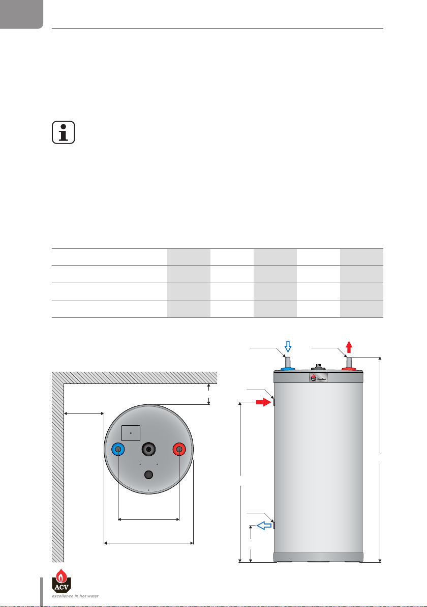
DIMENSIONS
A mm 845 1005 1205 1475 1720
B mm 580 740 940 1210 1455
C mm 215 215 215 215 210
D Ø 1" 1" 1" 1"1/4 1"1/4
100 130 160 210 240
50 mm
D
500 mm
B
360 mm
D
A
Ø 525 mm
en
8
661Y1000 • F
C
Page 9

INSTALLATION
1
1
5
9
6
3
1
2
4
7
8
10
EN
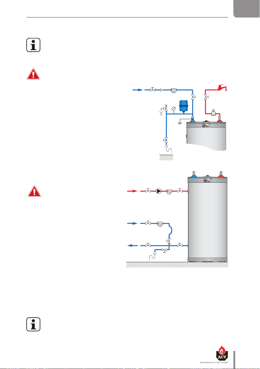
DOMESTIC HOT WATER
CONNECTION
The installation of a safety unit
iscompulsory.
To avoid water discharge on to the
tank, the safety unit must never
be installed above the tank.
In certain countries the domestic
kits must be approved and
included a temperature and
pressure relief valve fitted in the
hot outlet.
The circuit illustrations are basic
principle diagrams only.
To avoid any risk of corrosion,
connect the stainless steel tank
directly to the earth.
ACV recommends using
Hot water can burn!
apre-set thermostatic mixer
valve in order to provide hot
water at a maximum of 60°C.
• The installation of a domestic expansion
vessel avoids discharge from the safety
valve (loss of water).
• Capacity of domestic water vessels:
5 Litres: for models: 100 / 130
8 Litres: for models: 160 / 210
12 Litres: for model: 240
Refer to the manufacturer’s
technical instructions on the
expansion vessel for more details.
Connection to the DHW circuit
1. Isolating valve
2. Pressure reducer
3. Non-return valve
4. DHW expansion vessel
5. Safety valve
6. Drain down valve
7. Air vent valve
8. Hot water outlet
9. Pressure gauge
10. Earth connection
Recommendations
• The tank’s cold water supply pipe must
be fitted with a safety unit that includes
at least: an isolating valve (1), anon-re-
turn valve (3), a domestic safety valve
calibrated to 10 bar (5) and an expansion
vessel (4) of suitable size.
• When the operating pressure exceeds
6 bar, a pressure reducer (2) must be
installed before the safety unit.
• Union fittings are recommended for the
easy dismantling of the DHW connections. Ideally, the “dielectric” version is favourable to protect theconnections from
corrosion with the presence of different
metals such ascopper and galvanised
steel.
661Y1000 • F
en
9
Page 10

EN
INSTALLATION
DHW connection kit available
(code:1080 0102)
S
A. DHW temperature control valve
B. Mixed domestic hot water outlet
C. Cold water supply
D. Drainage connection
E. DHW expansion vessel connection
D
S. Safety valve (10 bar)
TH. Tank hot water outlet
TC. Tank cold water inlet
CONNECTION TO THE HEATING CIRCUIT
1. Heating isolating valve
2. Charging pump
3. Non-return valve
4. Preheater isolating valve
5. Primary circuit filling valve
6. Drain down valve
B
E
A
C
5
1
TC TH
21
3
4
3
4
5
6
POSITION OF DHW SENSOR
1
en
10
3
4
2
661Y1000 • F
Page 11
BRINGING INTO SERVICE
1
1
5
9
3
1
2
4
7
8
10
11
5
9
3
2
4
7
8
10
FILLING THE DHW TANK
Before bringing the hot water tank into service, check the connections to avoid any
any risk ofleaks during filling.
The sealing of the DHW tank must only be checked with the feed water.
Thetestpressure on the site must not exceed a pressure surge of 10 bar.
The DHW tank must always be filled and pressurised before filling and pressurising
the heating circuit.
• To vent the DHW installation, simply open
the highest hot water valve (8).
• Fill the domestic hot water tank, by opening
the stop valves (1).
• Close the hot water valve (8), after the water
flow has stabilised and the air has been
completely evacuated.
• Check all connections of the installation for leaks.
6
FILLING THE HEATING CIRCUIT
OF THE TANK
EN
Do not use vehicle or
21
4
3
non-dilutedantifreeze.
This can causeserious injury, lead
toloss of life or damage rooms.
• Check that the drainage valve (6) for your
5
3
primary installation is fully closed.
• Open the isolation valves (1) and (4) of the
• Open the air vent valve located in the
upper part of the hot water tank.
• In addition, follow the instructions
provided with the boiler for filling.
• Open the valves (5) to start filling.
heating circuit connected to the boiler.
1
4
5
6
• When the air is eliminated, first close the
airvent valve, then the filling valves (5).
• If antifreeze is needed in the primary circuit, it must comply with Public Hygiene Regulations
and must not be toxic. A food grade of Propylene Glycol is recommended. Consult the
manufacturer to determine the compatibility of the antifreeze with the tank ’s construction
materials.
Fill the system with the fresh tap water. Contact your ACV representative or installer
about the use of inhibitors.
en
661Y1000 • F
11
Page 12

EN
BRINGING INTO SERVICE
CHECKS BEFORE BRINGING INTO SERVICE
• Check that the safety valves (DHW) and (heating) are correctly installed and that the outlets
are connected to the drain.
• Check that the DHW tank and the primary circuit are filled with water.
• Check that the air has been correctly vented on both circuits.
• Check that the heater’s upper air vent valve is water tight.
• Check that the DHW and heating pipes are correctly connected and not leaking.
Recommendations
The risk of developing bacteria exists, including “Legionella pneumophila”,
ifaminimum temperature of 60°C is not maintained in both the storage tank
andinthe hot water distribution network.
In the event of small amounts of hot water repeatedly being drawn, a stratification
effect can develop in the tank. The upper hot water layer may then reach very high
temperatures.
A thermostatic mixer valve will ensure that extremely hot water does not run
fromthe taps.
Water heated for washing clothes, dishes and other uses can cause serious burns.
In order to avoid exposure to extremely hot water that can cause serious burns,
never leave children, old people, disabled or handicapped people in the bath
orshower alone.
12
Never allow young children to turn on the hot water or fill their own bath.
Adjust the water temperature in accordance with usage and plumbing regulations.
en
661Y1000 • F
Page 13

MAINTENANCE
PERIODIC CHECKS BY THE USER
• Check the pressure on the boiler pressure gauge: this should be between 0.5 and 1.5 bar.
• Each month visually inspect the valves, connections and accessories in order to detect any
leaks or malfunction.
• Periodically check the air vent valve located in the upper part of the tank to ensure that
itisnot leaking.
• Check the DHW safety valves are in good working order.
• In the event of a problem, please contact an engineer or your installer.
ANNUAL MAINTENANCE
The annual maintenance service, performed by an engineer, must include:
• A check of the air vent valve:
The venting of air can lead to the need for adding water to the system.
Check the pressure on the boiler’s pressure gauge.
• The manual activation of the DHW safety valve once a year.
This operation will lead to a discharge of hot water.
Before draining hot water through the safety valve, ensure that the outlet goes
directly to the drain to avoid any risk of burning and potential damage as a result.
• The discharge pipe must be open to the outside.
• If the safety unit drips periodically, this may be due to an expansion problem or clogging
ofthe valve.
• Follow the circulator’s maintenance instructions.
• Check that the valves are in good working order.
EN
Drain valve
Recommendations
Drain the tank if it is not used in winter and is at risk from exposure to ice.
If the primary circuit water contains antifreeze, only the DHW tank must be drained.
Before draining the DHW, isolate the tank and lower the pressure of the primary
circuit to 1 bar, in order to protect the DHW tank from crushing.
If the heating circuit does not contain antifreeze, the heating circuit and domestic
water must be drained. Always drain the heating circuit before draining the DHW.
661Y1000 • F
en
13
Page 14

EN
MAINTENANCE
DRAINAGE O F THE HEATING TANK
To drain the primary circuit of the hot water heater:
• Isolate the hot water primary circuit
byclosing valves (A) and (B).
• Connect the drain valve (C) to the drain
using a flexible hose.
• Open the drain valve (C) and drain
thewater from the primary circuit
tothedrain.
• Open the tank’s air vent valve (D)
toaccelerate drainage.
• Close the drain valve (C) and air vent (D)
after draining the tank.
DRAINAGE O F THE DHW TANK
To drain the hot water heater’s DHW tank:
• Close the isolation valves (1).
• Connect the drain valve (2) to the drain using
a flexible hose.
D
A
B
C
1
1
3
• Open the drain valve (2) and drain the water
from the DHW tank to the drain.
• Open the circuit’s air vent valve (3)
toaccelerate the tank’s drainage.
• Close the drain valve (2) and the air vent
valve(3) after draining the cylinder’s
DHWtank.
en
14
2
661Y1000 • F
 Loading...