

Page 1
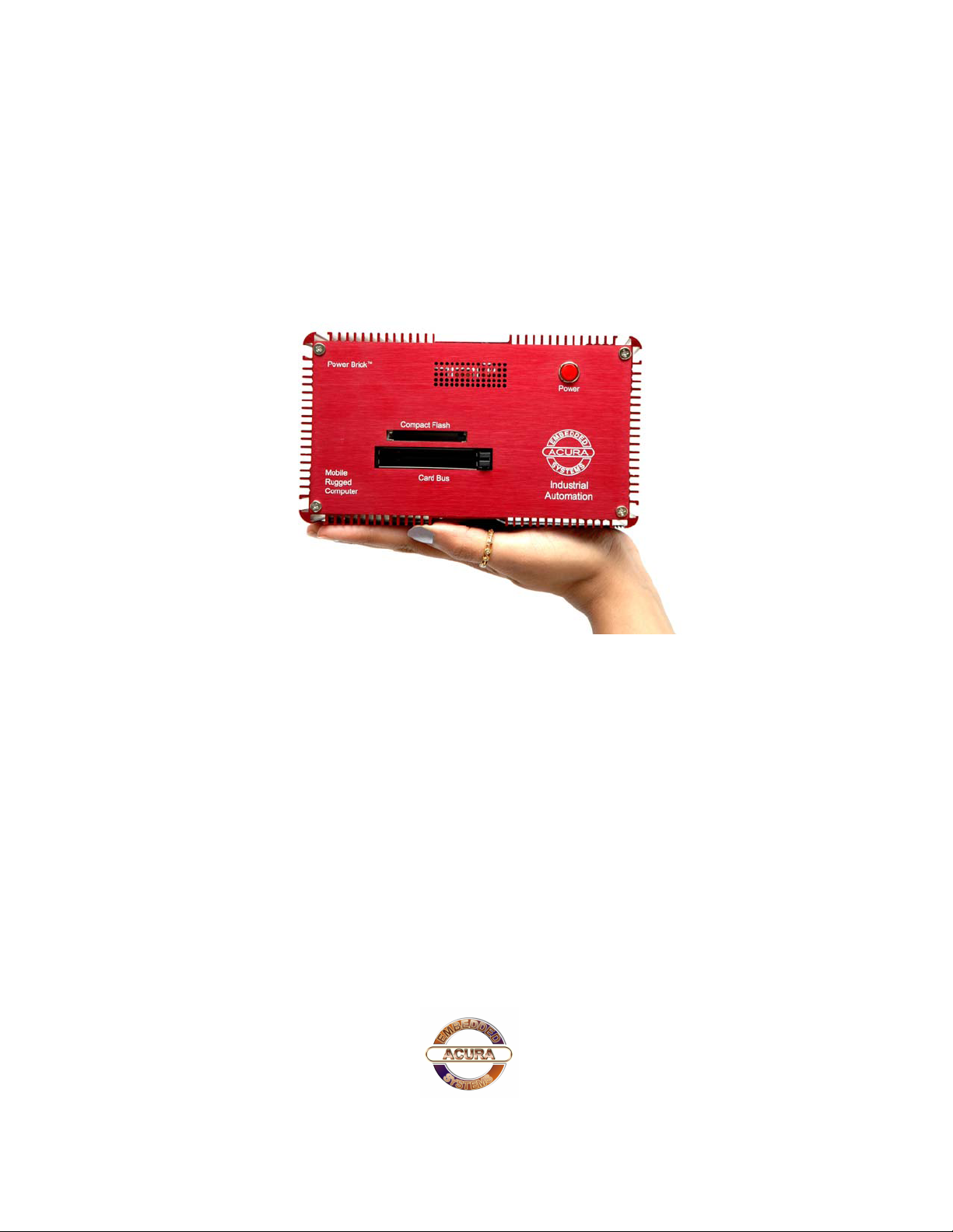
PowerBrick
User’s Manual
Edition 2.0
Small footprint rugged Pentium-M
Industrial Computer
Page 2

PowerBrick User’s Manual
Preface
Copyright
The material in this document is the intellectual property of Acura Embedded Systems Inc. This
publication, including all photographs, illustrations and software, is protected under international
copyright laws, with all rights reserved. Neither this manual, nor any of the material contained herein,
may be reproduced without written consent of Acura Embedded Systems Inc.
Version 1.2
Trademark Recognition
Microsoft, MS-DOS and Windows are registered trademarks of Microsoft Corp.
IBM PC is a registered trademark of International Business Machines Corporation.
Intel, MMX, Pentium, Pentium-II, Pentium-III, Pentium-4, Celeron are registered trademarks of Intel
Corporation.
AWARD is a registered trademark of AWARD International Inc.
Other product names used in this manual are the properties of their respective owners and are
acknowledged.
Disclaimer
Acura Embedded Systems Inc. takes every care in the preparation of this document, but no guarantee
is given as to the correctness of its contents. Our products are under continual improvement and we
reserve the right to make changes without notice. The manufacturer makes no representations or
warranties with respect to the contents hereof and specifically disclaim any implied warranties of
merchantability or fitness for any particular purpose. The manufacturer reserves the right to revise this
publication and to make changes from time to time in the content hereof without obligation of the
manufacturer to notify any person of such revision or changes.
In general, the manufacturer will not be liable for loss of data or other direct, indirect, special, incidental
or consequential damages arising from the use or inability to use the product or documentation, even if
advised of the possibility of such damages
.
i
Page 3

Table of Content
1. OVERVIEW
2. INSTALLATION……………………………………….….1
2.1 CONTENTS OF THE COMPUTER BOX………………...1
2.2 CONNECTING CABLES AND GETTING STARTED…..1
2.3 MOUNTING IN YOUR VEHICLE (FINAL LOCATION)....3
2.4 MOUNTING TOOLS………………………………………..3
2.5 COMPUTER INSTALLATION……………………………..3
3. TECHNICAL INFORMATION…………………………..5
3.1 BIOS SETUP………………………………………………….5
PowerBrick User’s Manual
3.2 OPERATING SYSTEMS…………………………………….5
3.3 OPERATING SYSTEM RESTORE PROCESS…………..6
3.4 WINDOWS EMBEDDED XP………………………………..6
3.5 LINUX EMBEDDED………………………………………….6
3.6 APPLICATION SOFTWARE………………………………..6
3.7 SPECIFICATIONS FOR POWERBRICK………………….7
3.8 OPERATION AND MAINTENANCE……………………….8
3.9 WARNING…………………………………………………….8
3.9A POWER BRICK WIRING DIAGRAM……………….…….9
4. CONTACT INFORMATION……………….……………….10
ii
Page 4

1. Overview
The PowerBrick is a Pentium-M system with 1.7 GHz processor speed. This small, rugged and
powerful computer is the premium choice when desktop computer performance is required in
industrial computing applications. Small size does not necessarily mean limitations in computing
power.
The state-of-the-art PowerBrick comes loaded with an impressive video card, fast hard drive
(optionally flash drive) and memory, all at a competitive price. It is designed and built for great
performance in a variety of applications and environments. The design focuses on elements
essential for industrial use wile excluding unneccesary hardware. The architecture is modular which
allows for easy upgrading and expansions.
Areas of applications include:
• Fire engines and rescue vehicles
• Security and patrol vehicles
• Other emergency or public safety vehicles
• Cash carriers
• Seaport terminal container yard management
• Fleet management
The main features are:
• Pentium-M processor (1.7 GHz)
• Standard 2.5” hard disk, 40 GB
• 512 MB DDR RAM
• On-board 10/100 LAN, USB 2.0
• Built-in 8~36 VOLT DC
• Standard audio input channel (1)
• Embedded OS (optional)
• Wireless 802.11g (optional)
• GSM/GPRS/WiFi/CDMA/CDPD options
• GPS/AVL options
• Dimensions: 7.6” x 4.35” x 4.13” (W x L x H)
For installation, mounting and cable connections please see Section 2. Technical information
is available in Section 3.
Page 5
2. Installation
2.1. Contents of the Computer Box
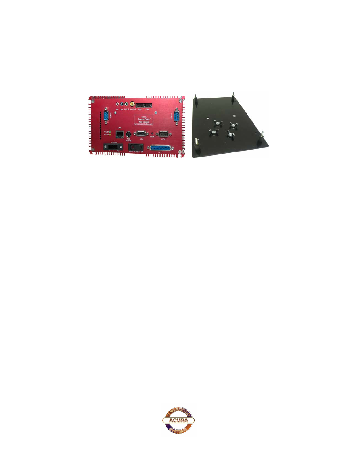
Figure 2.1 Box major components
PowerBrick User’s Manual
In the box you will find the following items: PowerBrick computer, power plug, mounting plate
equipped with rubber suspension, 4 bolts
If you have purchased Windows or Linux operating system with your computer, these CD’s should
be included. Keep them in a safe place.
Please see your separate monitor packaging for installation and other information for the touch
screen monitor.
Do not turn power on until you have read the next section and all cables are connected.
2.2. Connecting Cables and Getting Started
In order to get familiar with your system before mounting it at your vehicle (or final location), we
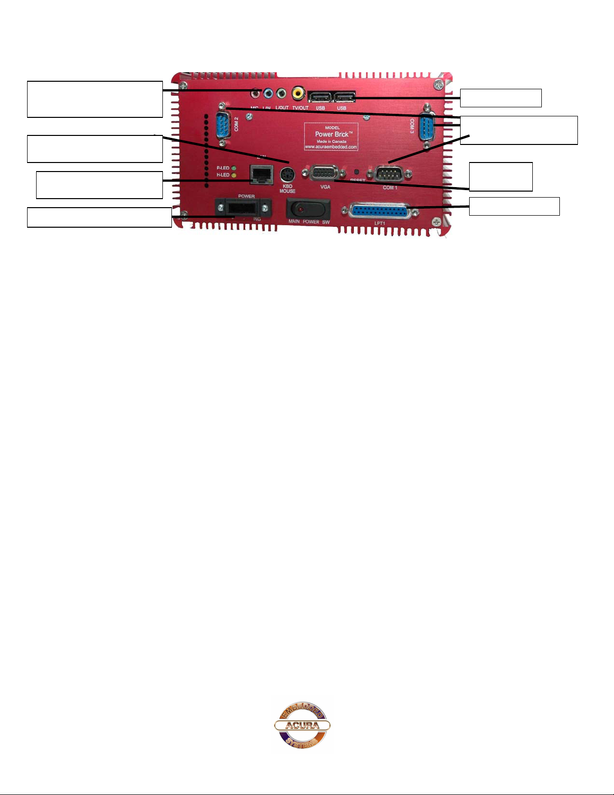
suggest you look at the connections on both ends of the computer such as shown in Figs. 2.2 and
2.3, connect up the unit, and place it into operation.
1
Page 6
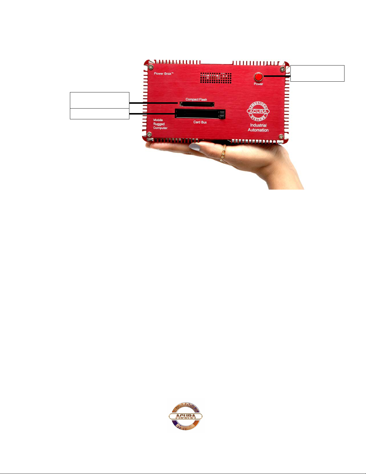
Compact Flash
PowerBrick User’s Manual
Power Button
Figure 2.2: Front side of PowerBrick
Connect all applicable cables such as:
? Keyboard
? Mouse
? Monitor
? Power supply cable
Optional device cables or units that you provide yourself could include the following:
? USB cable
? Speaker and microphone cables
? RJ45 Ethernet TP cable
? Parallel port printer-cable
? Serial port cable
2
Page 7
y
MIC, L-in, L-out, TV-out
port
PS/2 mouse/ key port
PowerBrick User’s Manual
Serial ports RS232
RJ 45 Ethernet port
DC in from power suppl
VGA port
Figure 2.3: Back side of PowerBrick
After connecting all applicable cables it is safe to power-on the system. (Warning: use either DC
from the dedicated power supply or AC, never both at the same time!)
2.3. Mounting in your vehicle or final location
This chapter provides you with the information of fixed system mounting. Prior to that, please
prepare the installation tools and appropriate items. If you are not clear about the items, contact
your dealer for information.
2.4. Mounting tools
For mounting your computer in a vehicle you need the following tools:
? Screw driver
? Drill
? Bolts and nuts appropriate to mount the plate in your vehicle
2.5. Computer installation
Mounting bolts and nuts for mounting to your specific vehicle are not provided, as there are many
variations of thickness that the unit might be mounted to. If mounting in a vehicle that is subject to
vibration and shock, It Is important to use the mounting plate with attached shock absorbers where
vibration could occur. The mounting plate should be fastened tightly with bolts and nuts. Please
ensure that if you mount any bolts/nuts under the computer, that they do not touch the computer
itself. Otherwise, the shock absorbers will not protect the computer properly.
3
Page 8
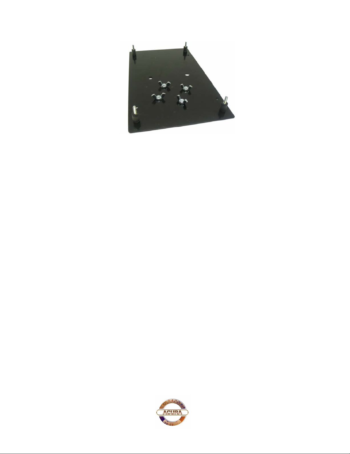
Figure 2.4: Mounting plate
PowerBrick User’s Manual
Connect all final wiring in a neat way, fastening it down with tie straps or other means to ensure that
it does not get caught and broken accidentally. Your car electrician will know appropriate ways to do
this.
4
Page 9
PowerBrick User’s Manual
3. Technical Information
3.1. BIOS Setup
The single board computer uses the Award BIOS (Basic Input/Output System) for the system configuration.
The Award BIOS in the single board computer is a customized version of the industrial standard BIOS for
IBM PC AT-compatible computers. It supports Intel x86 and compatible CPU architecture based processors
and computers. The BIOS provides critical low-level support for the system central processing, memory and
I/O sub-systems. The BIOS setup program of the single board computer let the customers modify the basic
configuration setting. The settings are stored in a dedicated battery-backed memory, NVRAM, retains the
information when the power is turned off. If the battery runs out of the power, then the settings of BIOS will
come back to the default setting. The BIOS section of the manual is subject to change without notice and is
provided here for reference purpose only. The settings and configurations of the BIOS are current at the time
of print, and therefore they may not be exactly the same as that displayed on your screen. To activate CMOS
Setup program, press <DEL> key immediately after you turn on the system. The following message “Press
DEL to enter SETUP” should appear in the lower left hand corner of your screen. When you enter the CMOS
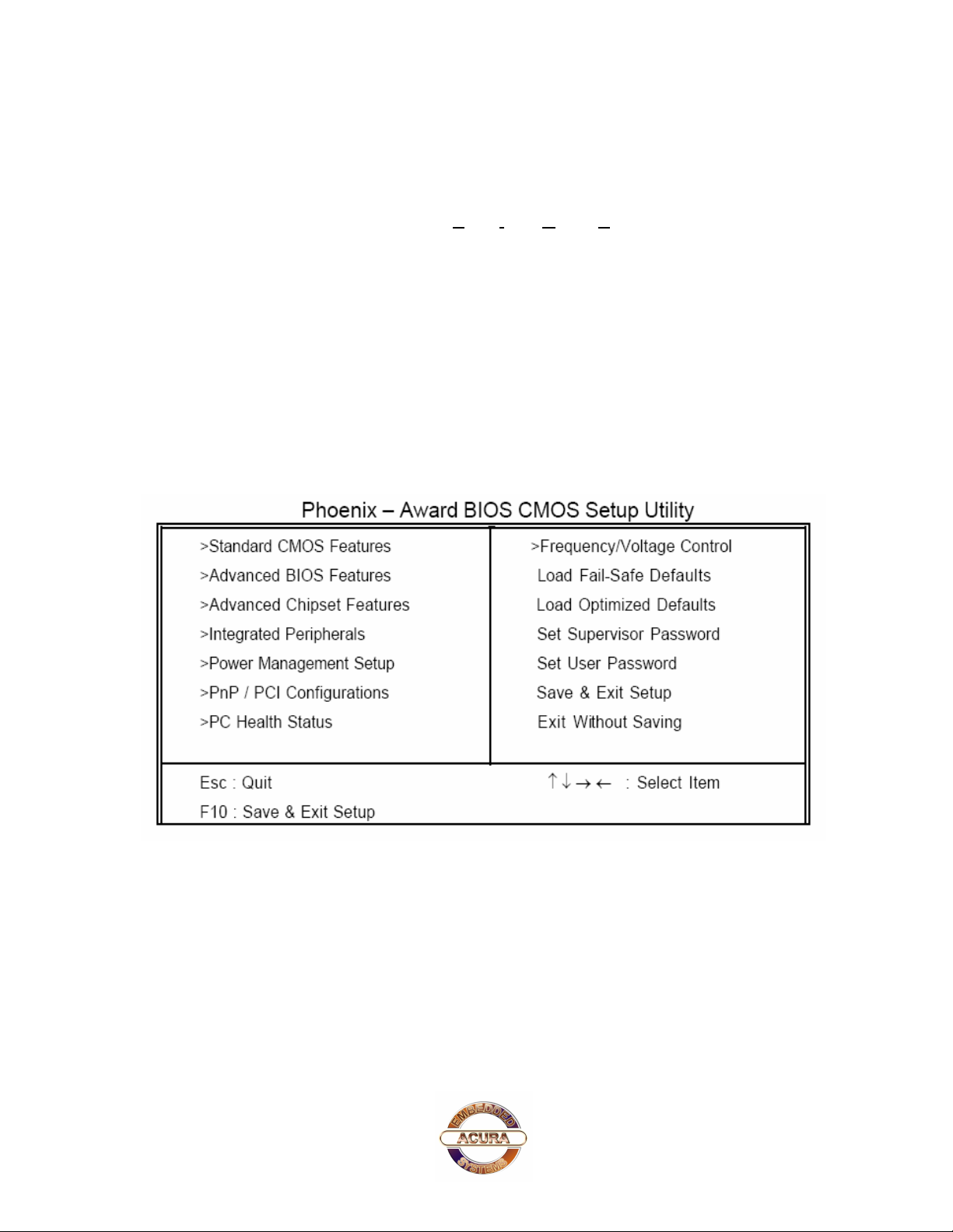
Setup Utility, the Main Menu will be displayed as in Table 3.2. You can use arrow keys to select your
function, press <Enter> key to accept selection and enter the sub-menu.
Table 3.1: Phoenix – Award BIOS CMOS Setup Utility
3.2. Operating Systems
The PowerBrick will generally be provided with a preinstalled operating system such as Windows
XP Professional, Embedded or Linux. To restore the operating system, follow the procedure
outlined in 3.4. You can also use an external CD-ROM drive to change, reinstall or repair the
operating system through a USB 2.0 port.
5
Page 10

PowerBrick User’s Manual
3.3. Operating System Restore Process
1. Back up your existing drive C:\ files.
2. Restart the computer.
3. Hold down the F8 key to enter Windows Advanced Boot Menu options.
4. Select “Return to OS Choices” and press “Enter”.
5. Select “Quick Restore Option”, press “Enter” and follow the instructions.
6. After re-boot, click on the “Touch screen” button in the “Restore drivers and software”
window and follow the instructions.
3.4 Windows XP Embedded
If you want to reinstall Windows XP Embedded, boot the computer, place the CD-ROM labeled
“Windows XP Embedded Recovery” into the external CD-ROM drive, press RESET and follow the
instructions on the screen. We recommend that this be done by experienced computer users only.
3.5 Linux Embedded
If you want to install Linux, boot the computer, place the CD-ROM labeled “Acura Embedded Linux”
into the external CD-ROM drive, press RESET and follow the instructions on the screen. Note: this
should only be done by an advanced user who has experience with Linux.
3.6 Application Software
You should be able to run all normal/generic application software such as Microsoft Word, Excel,
PowerPoint, Adobe software etc. if you have Windows installed. See the relevant manual/help
guides for the specific software. For Linux you will have to specifically select software designed for
Linux. Acura is not responsible for failure of any software on your computer but if you have any
particular software needs, please call Acura Technical Support or email
6
Page 11

3.7. Specifications for Power Brick
Table 3.3: System Features
Processor Intel Pentium M 1.7 GHz; VRM 10.0 standard
System FSB 533/400 MHz
Memory Support Dual-Channel mode, 2 DDR 400/333/266 DIMM up to
1GB
Video Integrated Intel Extreme Graphics 2, support 64MB DVMT
Audio Integrated AC '97, Realtek 650
Hard Disk Dual Independent ATA-100/66/33 support
Support up to 4 IDE devices on dual channel
CD-ROM None
LAN Intel Pro 10/100 Mb Fast Ethernet
USB 2.0 Integrated 4 independent OHCI controller supporting USB 1.1
ports; Integrated 1 EHCI controller supporting USB 2.0 ports;
Dynamic connection support to USB 2.0 or USB 1.1 devices
Hardware Monitor
Power Management
System, processor temperature, voltage and fan speed monitor.
Auto Thermal fan speed control
ACPI 1.0b compliance and OS direct power management, Wake-
on event: RTC/USB Keyboard/Modem/LAN/Keyboard/Mouse
PowerBrick User’s Manual
Dimensions
7.60“X 4.35“ x4.13“ (W x L x H)
Power 8 ~ 36V DC
Table 3.4: Input/Output
15 Pin VGA 1
PS/2 / KB & Mouse 1 / 1
Parallel Port 1
Mic-in 1
Line-Out 1
Speaker 1
USB 2.0/ 1.1 2
RJ45 Fast Ethernet 1
Serial Port RS232 2 (Optional 3)
8 ~ 36V DC Power Jack 1
7
Page 12
PowerBrick User’s Manual
3.8 Operation and maintenance
This module requires no routine maintenance. The green LED indicator when lit indicates proper
operation and health.
The power supply must be protected by a 15A auto fuse on the input line from the vehicle battery.
3.9 Warning
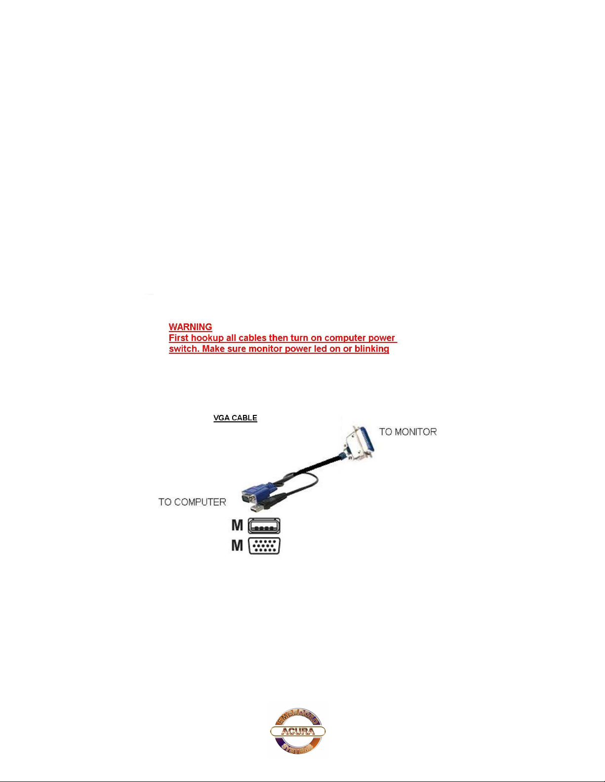
Before power up the computer, make sure all cables connected to the computer and the monitor.
8
Page 13
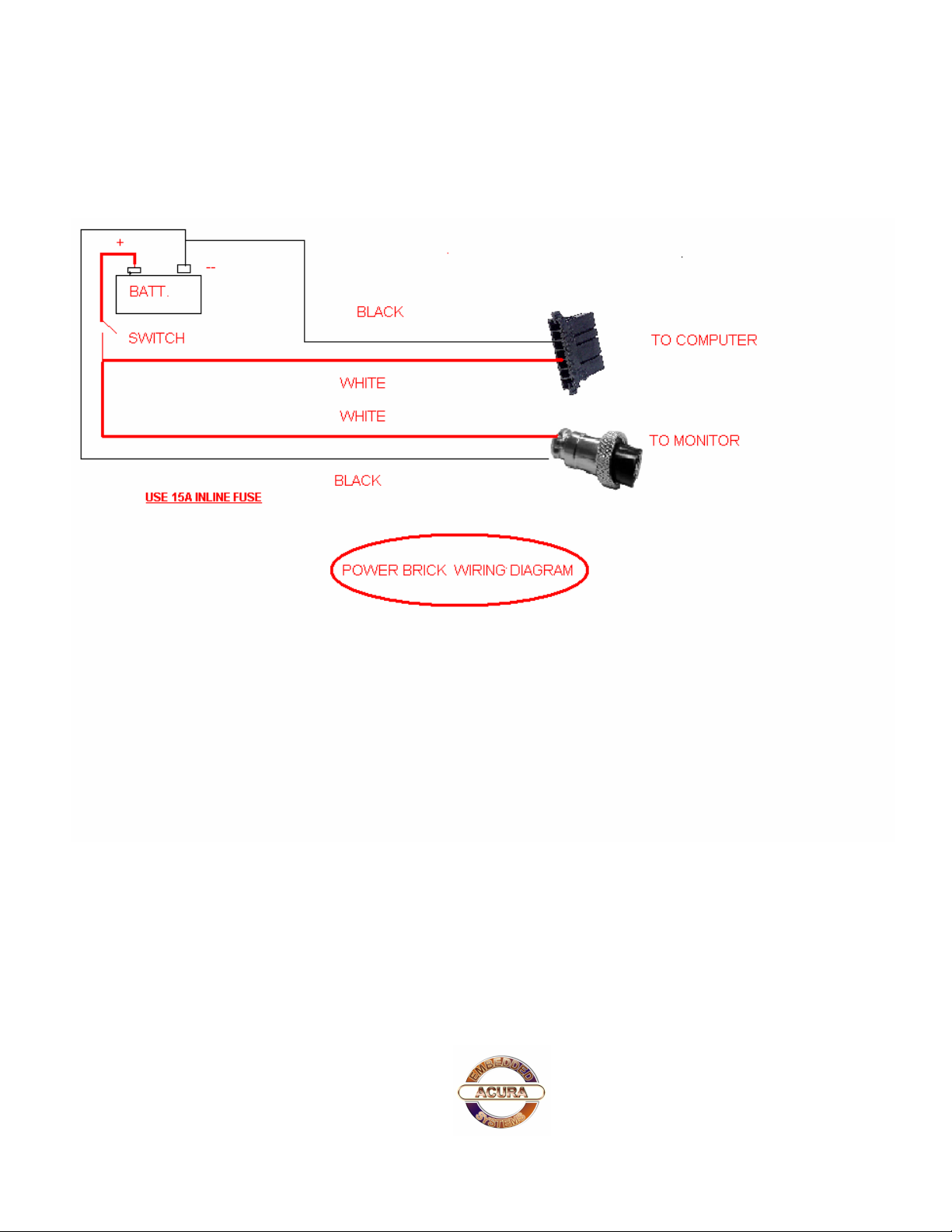
3.9A Power Brick Wiring Diagram
PowerBrick User’s Manual
9
Page 14

PowerBrick User’s Manual
4.Contact Information
With the unique set of products, Acura Embedded Systems remains committed to its goal of
providing trouble-free and customer-friendly service. A special customer service unit has been set
up specifically to cater to our esteemed customers' needs.
Technical Support:
? Phone: 1-866-502-9666
? Email: [email protected]
Mail address:
Acura Embedded Systems Inc.
Unit #1, 7711-128th Street
Surrey, BC V3W 4E6
CANADA
Ph: (604) 502-9666 Fax: (604) 502-9668
Toll Free 1.866.502.9666
www.a c ura embe dded.com
10
 Loading...