

Acura Music Link 08A31-0F1-000, MDX 2007, Music Link 08B28-STX-2000-91, Music Link 08A28-1H2-101, Music Link 08A28-1H1-800 User Manual
...Page 1
INSTALLATION
INSTRUCTIONS
Accessory Application Publications No.
ACURA MUSIC LINK
(FOR iPod
®
)
2007 MDX
BII 32726-34939
Issue Date
MARCH 2007
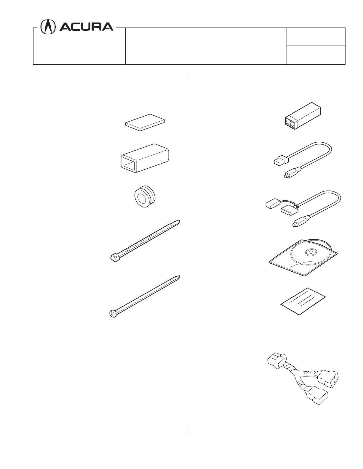
PARTS LIST
Attachment Kit (sold separately)
P/N 08A28-1H1-800
4 Cushion tapes
Holder cushion
Grommet
8 Wire ties
Acura Music Link Kit (sold separately)
P/N 08A28-1H2-101
Acura Music Link unit
Bus cable
Music Link harness
CD-ROM
(for home computer use only)
2 Long wire ties
Quick reference guide
Y-Harness Adapter (sold separately)
P/N 08A31-0F1-000
Y-harness adapter
© 2007 American Honda Motor Co., Inc. - All Rights Reserved. BII 32726-34939 (0703) 1 of 7
iPod® is a registered trademark of Apple Computer, Inc.
08B28-STX-2000-91
Page 2

TOOL AND SUPPLIES REQUIRED
#2 Phillips screwdriver
Flat-tip screwdriver
Ratchet
10 mm Socket
10 mm Combination wrench
Tape measure
Felt-tip pen
Isopropyl alcohol
Shop towel
Masking tape
Illustration of the Acura Music Link Installed on the
Vehicle
3. Remove the passenger's side under cover (five
clips, and release the two pins and two vehicle
connectors).
VEHICLE
CONNECTORS (2)
CLIPS (5)
BUS
CABLE
AUDIO
UNIT
ACURA MUSIC
LINK UNIT
Y-HARNESS
ADAPTER
MUSIC LINK
HARNESS
5N15111S
INSTALLATION
Client Information: The information in this
installation instruction is intended for use only by
skilled technicians who have the proper tools,
equipment, and training to correctly and safely add
equipment to your vehicle. These procedures should
not be attempted by “do-it-yourselfers.”
PASSENGER'S
SIDE UNDER
COVER
PINS (2)
4. Open the glove box. Remove the damper rod
cover and release the damper rod. Lower the
glove box while pushing in on the left and right
sides.
DAMPER
ROD
COVER
5N14011S
1. Make sure you have the anti-theft code for the
radio, then write down the frequencies for the
GLOVE BOX
6411050S
preset buttons.
2. Disconnect the negative cable from the battery.
2 of 7 BII 32726-34939 (0703) © 2007 American Honda Motor Co., Inc. - All Rights Reserved.
Page 3

5. Remove the right side dashboard cover (four
retaining tabs).
RETAINING
TABS (2)
7. Using a flat-tip screwdriver and a shop towel,
remove the driver's side center trim (five clips and
three retaining tabs).
FLAT-TIP
SCREWDRIVER
CLIPS (5)
SHOP
TOWEL
RETAINING
TABS (2)
RIGHT SIDE
DASHBOARD
COVER
5N14030S
6. Remove the right dashboard trim (one self-tapping
screw, ten clips, and three retaining tabs).
DRIVER'S
SIDE CENTER
TRIM
5N14051S
RETAINING
TABS (3)
8. Remove the center panel lower trim (two clips).
CLIPS (2)
RIGHT
DASHBOARD
TRIM
RETAINING
TABS (3)
© 2007 American Honda Motor Co., Inc. - All Rights Reserved. BII 32726-34939 (0703) 3 of 7
SELF-TAPPING
SCREW
CLIPS (10)
CENTER PANEL
LOWER TRIM
5N14061S
5N14040S
Page 4

9. Attach four pieces of masking tape to protect the
center console in the area shown.
12. Insert the Acura Music Link unit into the holder
cushion.
VEHICLE
CONNECTORS (9)
BOLTS (4)
AUDIO UNIT
CENTER
CONSOLE
MASKING TAPE
5N14071S
10. Remove the audio unit (four bolts). Pull the audio
unit out and unplug the nine vehicle connectors.
11. Get the Music Link harness. Measure and mark
the Music Link harness at the location shown
using a felt-tip pen.
FELT-TIP PEN
MARK
MUSIC LINK
HARNESS
ACURA
MUSIC LINK
UNIT
HOLDER
CUSHION
6905090B
Align ends.
13. Plug the bus cable DIN connector (black) and the
Music Link harness DIN connector (white) into the
Music Link unit.
NOTE: To avoid connector damage, orient the
connectors properly with the flat side up, and
insert them straight in (not crooked). To remove,
pull back on the slide collar to release a locking
mechanism. Do not pull on the cable, or you can
damage it.
ACURA MUSIC
LINK UNIT
MUSIC LINK
700 mm
5N15011S
BUS CABLE
DIN CONNECTOR
(BLACK)
Upside
HARNESS DIN
CONNECTOR
(WHITE)
Upside
6903010H
4 of 7 BII 32726-34939 (0703) © 2007 American Honda Motor Co., Inc. - All Rights Reserved.
Page 5

14. Secure the Acura Music Link unit to the steering
hanger beam with two long wire ties as shown.
17. Using isopropyl alcohol on a shop towel, clean the
area where the cushion tape will attach.
AUDIO UNIT
OPENING
BUS
CABLE
FRONT
ACURA MUSIC LINK UNIT
WIRE TIE
LONG
WIRE
TIE
LONG WIRE
TIES
STEERING
HANGER
BEAM
ACURA
MUSIC LINK
UNIT
5N15051S
MUSIC LINK
HARNESS
VEHICLE BRACKET
(Clean with
isopropyl alcohol.)
VEHICLE
HARNESS
WIRE TIE
Align the mark
made in step 11
with the wire tie.
CUSHION
TAPE
6411010S
15. Route the bus cable to the audio unit opening and
secure the bus cable to the vehicle harness with
one wire tie.
16. Connect two wire ties together, and secure the
Music Link harness to the steering hanger beam
with wire ties.
MUSIC LINK
HARNESS
STEERING
HANGER BEAM
WIRE
TIE
18. Attach the cushion tape to the edge of the vehicle
bracket in the area shown.
19. Secure the Music Link harness to the vehicle
harness with one wire tie at the mark you made in
step 11.
5N15061S
© 2007 American Honda Motor Co., Inc. - All Rights Reserved. BII 32726-34939 (0703) 5 of 7
Page 6

20. Bundle up the excess Music Link harness, and
secure it to the vehicle harness with one wire tie.
VEHICLE
HARNESS
WIRE TIE
22. Make the length of the Y-harness adapter 14-pin
connector the same length as the vehicle
connectors. Bundle up the excess length of bus
cable, and secure it to the vehicle harness with
three wire ties.
MUSIC LINK HARNESS
(Bundle up.)
6411020S
21. Get the Y-harness adapter. Plug the bus cable
14-pin connector and vehicle 14-pin connector into
the Y-harness adapter 14-pin connector.
BUS CABLE
14-PIN CONNECTOR
VEHICLE HARNESS
WIRE TIE
VEHICLE
CONNECTORS
5N15080S
WIRE
TIES
Y-HARNESS
ADAPTER 14-PIN
CONNECTOR
BUS CABLE
(Bundle up.)
(Align.)
23. Plug the vehicle connectors and the Y-harness
adapter 14-pin connector to the audio unit, and
reinstall the audio unit.
VEHICLE 14-PIN
CONNECTOR
Y-HARNESS
ADAPTER
5N15070S
VEHICLE
CONNECTORS
AUDIO UNIT
VIEW FROM THE BACK SIDE
BOLTS (4)
AUDIO UNIT
Y-HARNESS ADAPTER
14-PIN CONNECTOR
5N15091S
6 of 7 BII 32726-34939 (0703) © 2007 American Honda Motor Co., Inc. - All Rights Reserved.
Page 7

24. Reinstall the damper rod and cover. Be careful not
to pinch the Music Link harness when closing the
glove box.
DAMPER
ROD COVER
MUSIC LINK
HARNESS
GLOVE BOX
6411060S
25. Check that all wire harnesses are routed properly
and all connectors are plugged in.
26. Reinstall all removed parts. Check that all clips
and other fasteners are installed securely.
27. Reconnect the negative cable to the battery.
28. Enter the client's audio and navigation system (if
equipped) anti-theft code. Then reset the XM radio
presets and the clock.
29. Give the CD-ROM disc to your customer. This
disc is software for use on home computers, and
it also contains an owner's manual.
30. Turn the audio unit ON. Check that CDC EJECT,
or CD4 EJECT is shown on the audio unit display
while in the AUX mode (the Music Link is
recognized as an accessory CD changer).
31. Check the operation of the security system
according to the security system user's
information provided.
© 2007 American Honda Motor Co., Inc. - All Rights Reserved. BII 32726-34939 (0703) 7 of 7
 Loading...