

Page 1
Changzhou ACT Motor Co., Ltd
motor
Stepper Motor Dirver
DM
The latest 32-bit digital processing technology
Optically isolated differential signal input
Ultra low vibration noise
Built-in micro-segmentation
Easy current setting, can be switched between 0.7~4.2A
Integrated parameter power-on auto-tuning function
Subdivision setting (400~25600)
With overcurrent, overvoltage, undervoltage protection
Storage environment
The drive power supply DC power supply is universal, the DC power supply range is
24~50VDC, and the DC power supply has positive and negative power supply antireverse connection functions.
1) The larger the actual current of the motor, the greater the output torque, but the
more copper loss (P=I²R) of the motor, the more heat the motor generates;
2) The higher the supply voltage of the driver, the higher the high-speed torque of the
3) It can be seen from the moment frequency characteristic diagram of the stepping
motor that the high speed is smaller than the medium and low speed torque.
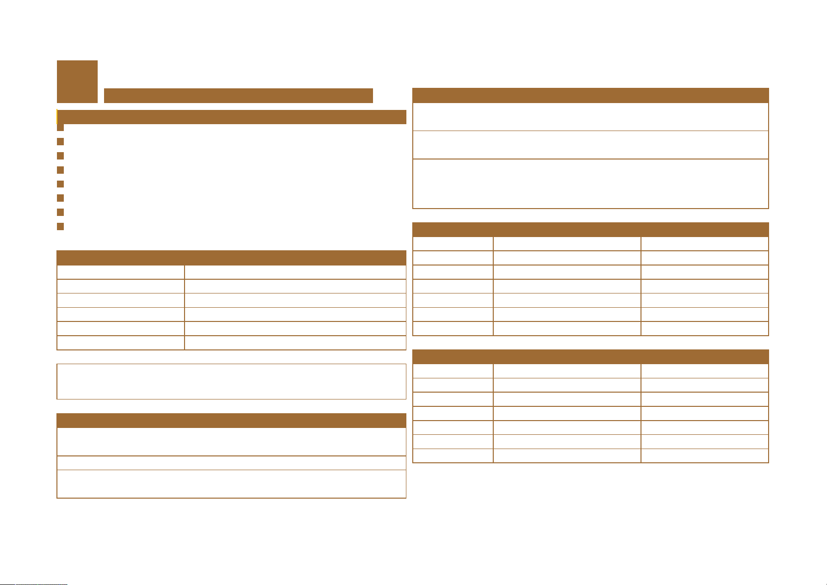
DM542
MicroSteps Setting:400~25600 DC:24~50V
Overview
Features A+ Phase A+
Input voltage
Output current
Pulse frequency
MicroSteps
Using environment
The characteristic of the output torque
Avoid high temperatures, oil mist, dust, corrosive gases
-20~+65℃,avoid direct sunlight
24~50VDC
0.7~4.2A (PEAK)
0~100KHz
16 MicroSteps
Strengthen the heat dissipation method
1) The reliable operating temperature of the driver is usually within 60 ° C, and the motor
operating temperature is within 80 ° C;
2) Select the automatic semi-flow mode when using, the current will be automatically
reduced by half when the motor stops, to reduce the heat of the motor and the drive;
3) When installing the driver, please install it on the vertical side to make the heat
dissipating teeth form a strong air convection; if necessary, install a fan near the driver to
force heat dissipation to ensure the driver works within the reliable working temperature
range.
Motor and power
Symbol Name Remark
A- Phase A-
B+ Phase B+
B- Phase B-
DC+ input power + 24~50V
DC- input power - GND
Control signal
Symbol Name Remark
PUL+ Pulse signal + /
PUL- Pulse signal - /
DIR+ Direction signal+ /
DIR- Direction signal- /
ENA+ Enable signal + Only connected when used
ENA- Enable signal - Only connected when used
Tel: 0519-81189628/81189728 Fax: 0519-81189528 Address: No.18.boyang Road.Jintan District,Changzhou Ctiy,Jiangsu Province, China Post Code: 213000
Web:http://www.act-motor.com
Page 2
Changzhou ACT Motor Co., Ltd
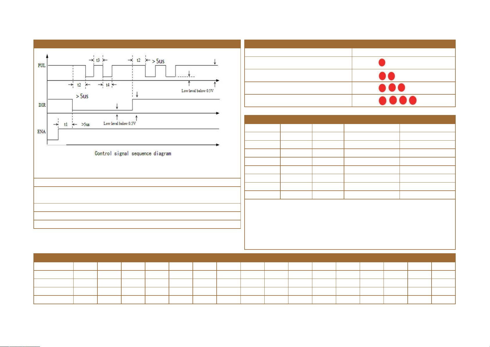
Control signal sequence diagram LED status indication
Note:
T1: ENA (enable signal) should be determined to be high by a DIR of at least 5 μs.In general, it is
recommended that ENA+ and ENA- be left floating.
T2: DIR determines its state high or low at least 2 μs along the PUL falling edge.
T3: The pulse width is at least not less than 2.5 μs.
T4: The low level width is not less than 2μs.
Drive working status Symptom
Overcurrent Protection
Overvoltage protection
Undervoltage protection
Phase loss protection
DIP switch setting
SW1 SW2 SW3 PEAK RMS
ON ON ON 1.00A 0.71A
OFF ON ON 1.46A 1.04A
ON OFF ON 1.92A 1.36A
OFF OFF ON 2.37A 1.69A
ON ON OFF 2.84A 2.03A
OFF ON OFF 3.32A 2.36A
ON OFF OFF 3.76A 2.69A
OFF OFF OFF 4.20A 3.00A
SW4: The quiescent current can be set by the SW4 dial switch. OFF means that the
quiescent current is set to half of the dynamic current. ON means that the quiescent
current is the same as the dynamic current. In general use, SW4 should be set to ON, so
that the heat generated by the motor and the driver is reduced, and the reliability is
improved. After about 30ms, the current is automatically reduced to about half (60% of
the actual value), and the calorific value is theoretically reduced to 30%.
Microsteps setting
RPM Default 400 800 1600 3200 6400 12800 25600 1000 2000 4000 5000 8000 10000 20000 25000
SW5 ON OFF ON OFF ON OFF ON OFF ON OFF ON OFF ON OFF ON OFF
SW6 ON ON OFF OFF ON ON OFF OFF ON ON OFF OFF ON ON OFF OFF
SW7 ON ON ON ON OFF OFF OFF OFF ON ON ON ON OFF OFF OFF OFF
SW8 ON ON ON ON ON ON ON ON OFF OFF OFF OFF OFF OFF OFF OFF
Tel: 0519-81189628/81189728 Fax: 0519-81189528 Address: No.18.boyang Road.Jintan District,Changzhou Ctiy,Jiangsu Province, China Post Code: 213000
Web:http://www.act-motor.com
Page 3
Changzhou ACT Motor Co., Ltd
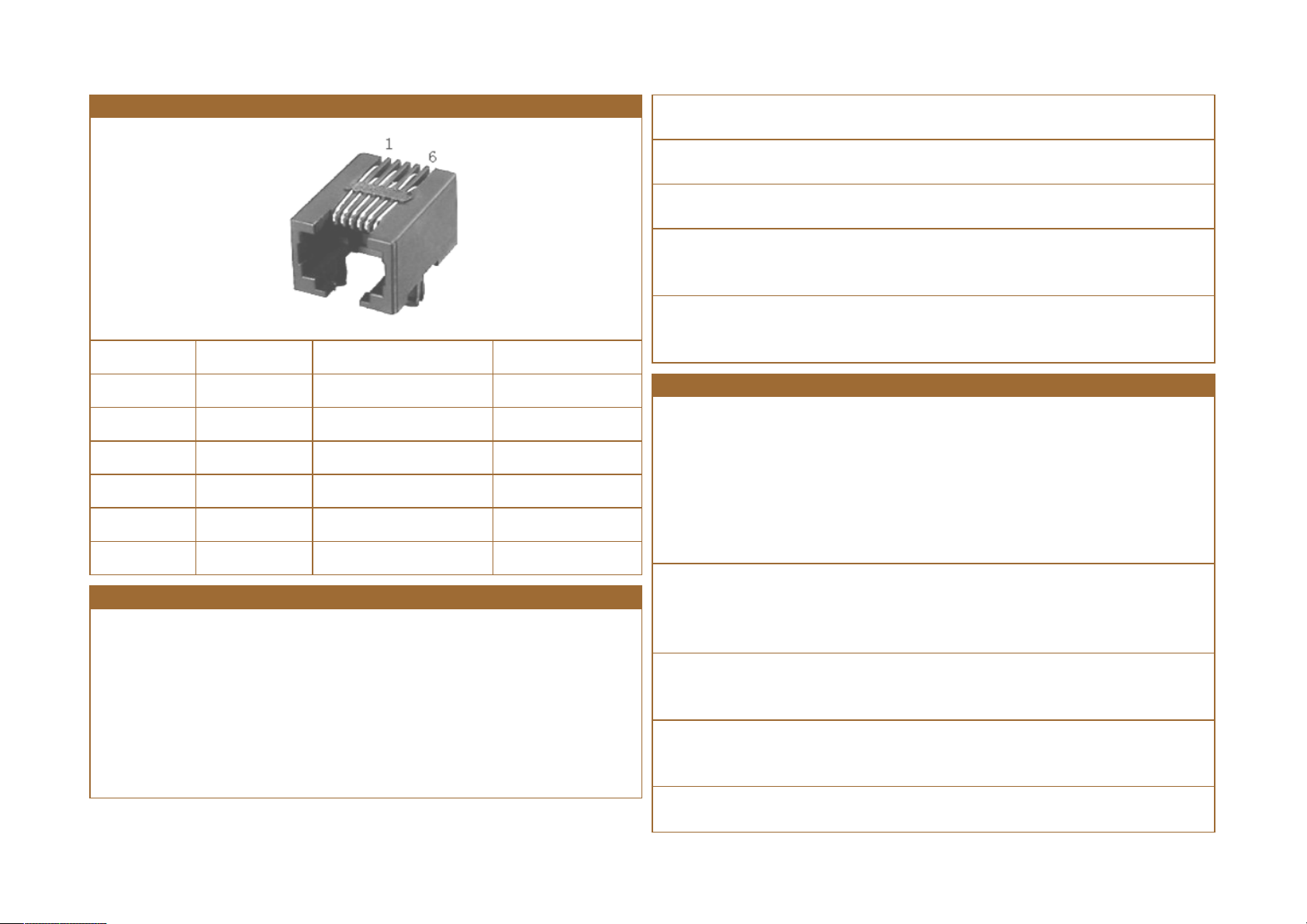
Communication port
Terminal number symbol name Description
1 NC
2 +5V Positive power terminal External STU only
3 TxD Sending end
4 GND Power ground 0V
5 RxD Receiving end
6 NC
Output current setting value
For the same motor, the larger the current setting value, the larger the motor output
torque,but the heat of the motor and the driver is also more serious when the current is
large. The magnitude of the specific heat generation is not only related to the current set
value, but also to the type of exercise and the dwell time. The following setting method
uses the rated current value of the stepping motor as a reference, but the optimum
value in practical applications should be adjusted based on this. In principle, if the
temperature is very low (<40 °C), the current setting value can be appropriately
increased to increase the motor output power (torque and high-speed response).
1) Four-wire motor: The output current is set to be equal to or slightly smaller than the
rated current of the motor;
2) Six-wire motor high torque mode: the output current is set to 50% of the rated current
of the motor unipolar connection;
3) Six-wire motor high-speed mode: the output current is set to 100% of the rated current
of the motor unipolar connection;
4) Eight-wire motor series connection method: the output current can be set to 70% of the
rated current of the motor unipolar connection;
5) Eight-wire motor and connection method: The output current can be set to 140% of the
rated current of the motor unipolar connection.
Wiring requirements
1) In order to prevent the driver from being disturbed, it is recommended to use the
shieldedcable for the control signal, and the shield layer is shorted to the ground wire.
Unless otherwise specified, the shielded cable of the control signal cable is grounded at
one end: theupper end of the shielded wire is grounded, and the shielded wire The drive is
suspended at one end. Only the grounding at the same point is allowed in the same
machine. If it is not a real grounding wire, the interference may be serious. At this time, the
shielding layer is not connected.
2) The pulse and direction signal lines and the motor lines are not allowed to be bundled
side by side, preferably separated by at least 10 cm. Otherwise, the motor noise easily
interferes with the pulse direction signal, causing the motor to be inaccurately positioned,
and the system is unstable.
3) If one power supply is provided for multiple drives, parallel connections should be
made at the power supply. It is not allowed to connect one to the other and then to
another chain.
4) It is forbidden to electrify the P2 terminal of the driver. When the charged motor
stops,there is still a large current flowing through the coil. Pulling the P2 terminal will
cause a huge moment to induce the electromotive force to burn the driver.
5) It is strictly forbidden to add the tin to the terminal after adding the tin, otherwise the
terminal may be overheated due to the contact resistance becoming larger.
Tel: 0519-81189628/81189728 Fax: 0519-81189528 Address: No.18.boyang Road.Jintan District,Changzhou Ctiy,Jiangsu Province, China Post Code: 213000
Web:http://www.act-motor.com
Page 4
Changzhou ACT Motor Co., Ltd
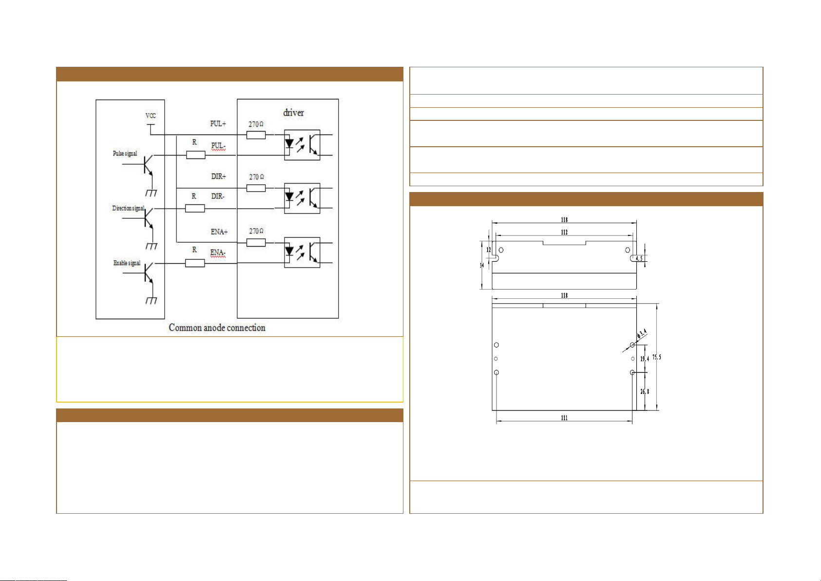
Control Signal Connection
The DM542 driver uses a differential interface circuit for differential signals, single-ended
common cathode and common anode interfaces, and a built-in high-speed optocoupler
that allows reception of long-line drivers, open-collector and PNP output circuits. In the
harsh environment, we recommend Long-line driver circuit with strong anti-interference
ability.
If using a regulated switching power supply, it should be noted that the output current
range of the switching power supply should be the largest.
1) Pay attention to the power supply when wiring, do not reverse
2) It is best to use an unregulated power supply
3) When using unregulated power supply, the power supply current output capability
should be greater than 60% of the drive set current.
4) When using a regulated switching power supply, the output current of the power
supply should be greater than or equal to the operating current of the driver.
5) In order to reduce costs, two or three drives can share one power supply.
Drive Dimensional Chart(mm)
Power supply
The power supply voltage can work normally within the specified range. The DQ856MA
driver is preferably powered by an unregulated DC power supply, or a transformer buck
+ bridge rectifier + capacitor filter. Note, however, that the rectified voltage ripple value
should not exceed its specified maximum voltage. It is recommended that the user
supply power with a DC voltage below the maximum voltage to avoid grid fluctuations
exceeding the driver voltage range.
Note: It is recommended to use side mounting for better heat dissipation. When designing
the mounting dimensions, pay attention to the terminal size and wiring!
Tel: 0519-81189628/81189728 Fax: 0519-81189528 Address: No.18.boyang Road.Jintan District,Changzhou Ctiy,Jiangsu Province, China Post Code: 213000
Web:http://www.act-motor.com
Page 5
Changzhou ACT Motor Co., Ltd
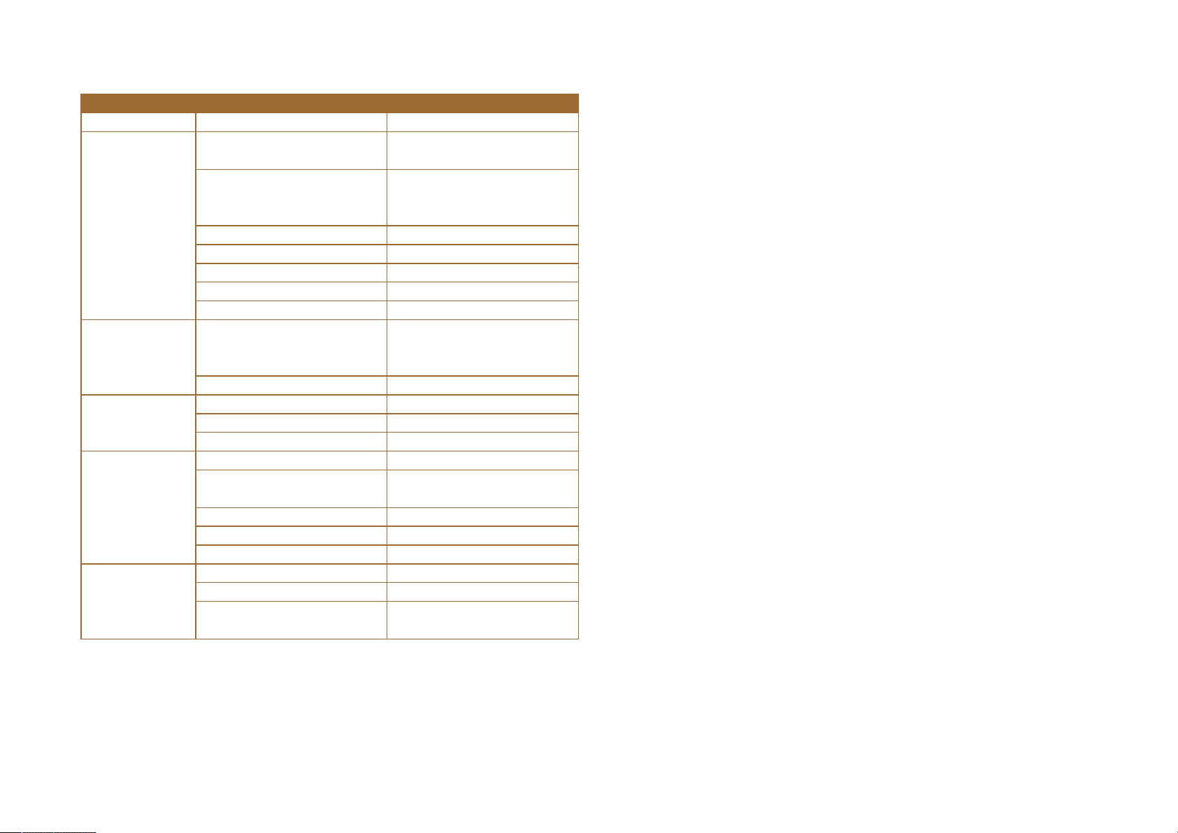
Problems and handle the law
phenomenon reason solution
Check the power supply circuit,
normal power supply
The pulse signal is weak and the
signal current is increased to 7-
Any two wires of the same phase of
theexchange motor
(A+ A-exchange position)
Reliable grounding
Appropriately increase the voltage or
The motor does
not run
Motor steering
error
Alarm indicator is
on
Inaccurate
location
Stall when the
motor
accelerates
Power light is not lit
Motor shaft is powerful
Subdivision is too small Selective segmentation
Current setting is too small Selective current
Drive is protected Power on again
Enable signal is low This signal is pulled high or not
Does not respond to control signals No power
Motor line is wrong
The motor line has an open circuit Check and pick up
Motor line is wrong Check wiring
Voltage is too high or too low Check the power supply
Motor or drive damage Replace the motor or drive
Signal interference Eliminate interference
The shield is not connected or not
connected
The motor line has an open circuit Check and pick up
Subdivision error Set the subdivision
Small current Increase current
Acceleration time is too short Accelerated acceleration time
Motor torque is too small Select a large torque motor
Low voltage or too small current
16mA.
current
Tel: 0519-81189628/81189728 Fax: 0519-81189528 Address: No.18.boyang Road.Jintan District,Changzhou Ctiy,Jiangsu Province, China Post Code: 213000
Web:http://www.act-motor.com
 Loading...