

Page 1

NGT-1
NMEA 2000 PC Gateway
For Actisense Comms API compatible software
User Manual
For variant:
NGT-1-USB
NGT-1-ISO
Issue 2.01
Page 2

Page 3

NMEA 2000 to PC Interface - NGT-1
Contents
Company information 4
Important Notices
Trademarks and Registered Trademarks 5
Fair use Statement
Technical Accuracy
Product Registration
Product Guarantee
Product Disposal
5
5
5
5
5
5
Product Overview 6
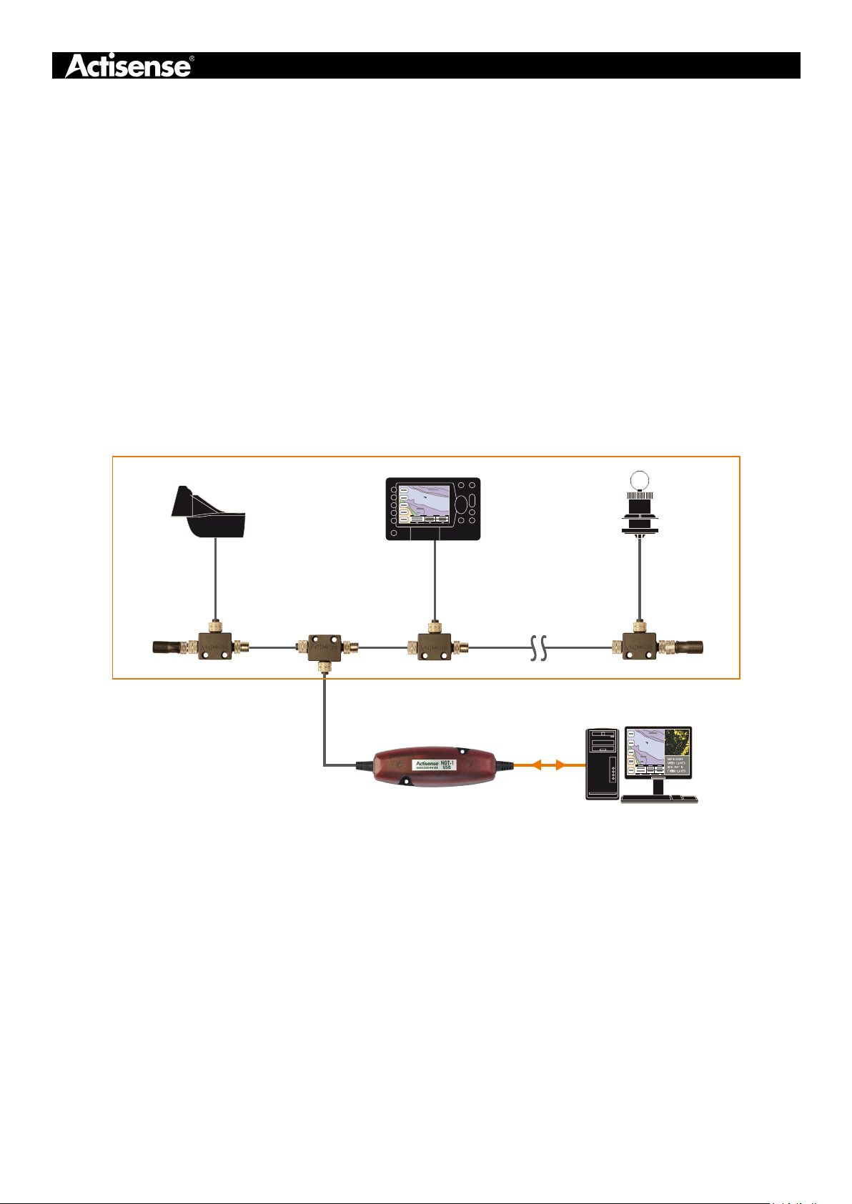
Figure 1 - Example of an NGT-1 Installation 6
Package Contents USB
Package Contents ISO
6
6
Installation Warnings 7
Mounting the NGT-1
Powering the NGT-1
Connecting to a USB Port
USB Driver Installation 8
Windows Port Number Conguration
8
8
8
8
Connecting to an NMEA 2000 Network 9
NMEA 2000 Networks 9
NMEA 2000 Minimum Network Requirements
Figure 2 - NMEA 2000 Minimum Network Requirements Diagram
9
9
Connecting the ISO cable 10
Table 2 - ISO Cable Connections 10
Connecting to an RS232 (PC) port
Figure 3 - PC / RS232 Port Connections
10
10
Connecting a Custom Cable 11
Opening the NGT-1 Case 11
Custom ISO/PC Cable
Custom NMEA 2000 Cable
Table 3 - NMEA 2000 Connection Table
Figure 4 - NMEA 2000 PCB Connections
11
11
11
11
Conguring the NGT-1 12
Conguration Requirements 12
Connecting the NGT-1 to NMEA Reader
Selecting PGNs for transfer
Changing the Baud rate
Special ARL P-codes
12
12
12
12
Troubleshooting Guide 13
Status LEDs 13
Table 4 - Diagnostic LED
Technical Support and the Returns Procedure
13
13
Page 3© 2015 Active Research Limited
Page 4

Specications 14
Minimum NMEA 2000 PGN List
NGT-1 Product Order Codes
16
15
Company information
Active Research Ltd
Unit 5 Wessex Trade Centre
Ringwood Road
Poole, Dorset
UK, BH12 3PF
Telephone: +44 (0)1202 746682
Email: [email protected]
Web: www.actisense.com
Page 4© 2015 Active Research Limited
Page 5
NMEA 2000 to PC Interface - NGT-1
Important Notices
The NGT-1 has been certied to comply with the European directive for Electromagnetic Compatibility
(EN60945) and is appropriately CE marked. Operation of the unit should be in conjunction with appropriate
CE approved shielded connectors and cabling used in accordance with the CE directive EN60945. Any
EMC related issues should be reported to Active Research Limited immediately to allow the company to
rectify or resolve EMC related problems in accordance with its obligations under EN60945.
If the unit is connected such that compliance failure occurs beyond the company’s control, the company shall not be
held responsible for compliance failure until suitable EMC guidelines for connection are seen to have been taken.
Trademarks and Registered Trademarks
Actisense® and the Actisense logo are registered trademarks of Active Research Limited. All other trademarks are the
property of their respective owners.
The NMEA® name and NMEA logo are copyright held by the NMEA. All uses in this manual are by permission and no
claim on the right to the NMEA name or logo are made in this manual.
Fair use Statement
The contents of this manual may not be transferred or copied without the express written permission of Active Research
Limited.
Copyright © 2013 Active Research Ltd. All rights reserved.
Technical Accuracy
To the best of our knowledge the information contained in this document was correct at the time it was produced. Active
Research Ltd cannot accept liability for any inaccuracies or omissions.
The products described in this manual and the specications thereof may be changed without prior notice. Active
Research Ltd cannot accept any liability for differences between the product and this document. To check for updated
information and specications please contact Active Research Limited.
Active Research Limited will not be liable for infringement of copyright, industrial property rights, or other rights of a third
party caused by the use of information or drawings described in this manual.
Product Registration
Please register your product via the online form.
Your product has a unique serial number which is needed to complete the product registration form. The serial number
is six digits and can be found below the barcode on the white label on the back of the NGT-1. If your NGT-1 is
inaccessible, you will nd the serial number under the product information on the ‘network list’ page of an NMEA 2000
MFD or using the freely available Actisense NMEA Reader software available from www.actisense.com
Your registration will assist Actisense Support to link your product to your details, simplifying any future assistance you
may require.
Product Guarantee
This product comes with a three year ‘return to base’ guarantee. If you suspect that the unit is faulty please refer to the
“Troubleshooting Guide” on page 13.
It is a requirement of the guarantee that all installations of electronic equipment follow the NMEA 0400 specication. Any
connection to a battery or power supply must meet the mandatory essential safety requirements that may be imposed
by local regulatory agencies.
Actisense products are intended for use in a marine environment, primarily for below deck use. If a product is to be used
in a more severe environment, such use may be considered misuse under the Active Research Limited guarantee.
Product Disposal
Please dispose of this product in accordance with the WEEE Directive. The product should be taken to a
registered establishment for the disposal of electronic equipment.
Page 5© 2015 Active Research Limited
Page 6
Product Overview
The Actisense NMEA 2000 to PC Interface (NGT-1) provides an easy way to link a PC to an NMEA 2000 network. The
NGT-1 makes it possible for software applications to read from and write to the NMEA 2000 bus whilst maintaining
network integrity.
• Able to transfer all NMEA 2000 PGNs
• Firewall enforces NMEA 2000 bus rules
• Galvanic Opto-isolation between the PC and the NMEA
2000 network
• ISO variant: ISO-Drive™ output compatible with RS422
and RS232
• Transfer list for selecting which NMEA 2000 PGNs are
sent and received
• Free Firmware updates provided when new features
are added - update in the eld via PC
• Two available variants for different installation
situations (see part code list on next page)
Figure 1 - Example of an NGT-1 Installation
NMEA 2000
®
• Pre-tted cables for ease of installation
• Screw terminals for easy installation of custom cables
if required
• Free SDK for software developers
• NMEA 2000 certication of software not mandatory; no
certication cost
• Only required to purchase NMEA 2000 Appendix B to
develop software
• Reduced software development time with Windows API
• Suitable for Windows, MAC and Linux applications
• Suitable for PC, mobile or embedded systems
• NMEA ‘Third Party Gateway’ status pending
A2K-TER-M
A2K-T-MFF
Note: Not to be used as wiring instructions
A2K-T-MFF A2K-T-MFF
NGT-1
Package Contents USB
1 x NGT-1-USB with NMEA 2000 Micro Male cable and USB male type A cable
1 x Actisense CD in sleeve (Documents and Software)
1 x NGT-1 User Manual
1 x Mounting Guide sheet
2 x Mounting screws
Package Contents ISO
1 x NGT-1-ISO with NMEA 2000 Micro Male cable and bare wire cable
1 x Actisense CD in sleeve (Documents and Software)
1 x NGT-1 User Manual
1 x Mounting Guide sheet
2 x Mounting screws
1 x Spare cable grommet (used if replacing the ISO/PC cable)
A2K-TER-F
Page 6© 2015 Active Research Limited
Page 7
NMEA 2000 to PC Interface - NGT-1
Installation Warnings
All warnings and notices must be followed to ensure the correct operation of the NGT-1. Incorrect
installation may invalidate the guarantee.
It is highly recommended that all of the installation instructions are read before commencing the installation.
There are important warnings and notes throughout the manual that should be considered before the
installation is attempted.
Warning 1: Accuracy
The Actisense NGT-1 is designed to reliably transfer NMEA 2000 PGNs between the PC and the NMEA 2000 bus; the
accuracy of data contained in each PGN is the responsibility of the generating device or software application. Furthermore
for each installation requirement the NGT-1 must be congured correctly by the software application. Therefore, the
NGT-1 should only be used as an aid to vessel monitoring, control or navigation and should not be used as a replacement
for traditional aids and techniques.
Warning 2: Installation and Operation
This product must be installed and operated in accordance with the instructions provided. Failure to do so could result
in personal injury, damage to your boat and/or poor product performance.
Warning 3: Installation Code of Practice
All wiring should be in accordance with the regional code of practice for installations and meet the NMEA 0400
specication.
Warning 4: Firmware Updates
It is highly recommended that the Firmware is kept up to date in the NGT-1. The latest rmware version number and
details of supporting software such as NMEA Reader can be found on the NGT-1 downloads web page. You can check
the rmware version currently installed in your NGT-1 by locating the manufacturers software ID on the network list
found in most NMEA 2000 MFDs or NMEA Reader.
Warning 5: Mounting Requirements
Select a at location to mount the NGT-1. Mounting on a contoured surface may cause damage to the case.
Do not mount the NGT-1 while the device is powered.
Do not mount the NGT-1 while the NMEA 2000 cable is connected.
Do not mount the NGT-1 while the PC cable is connected.
Warning 6: Mounting Locations
Do not mount the NGT-1 in the same plane as transmitting or receiving antennas.
Do not mount the NGT-1 close to an electronic compass.
Page 7© 2015 Active Research Limited
Page 8

Mounting the NGT-1
• Use the NGT-1 as a template to locate and mark the drill holes for mounting. Do not attempt to drill the holes while
the NGT-1 is in position. A mounting guide is provided and can be used to mark the mounting holes if preferred.
• Refer to “Warning 5: Mounting Requirements” on page 7.
• Secure directly to a bulkhead using the two M3.5 stainless steel pan-head screws provided. If these screws are lost,
suitable alternatives may be used instead. Note: Using larger screws can damage the housing and invalidate the
guarantee.
• Secure directly to a bulkhead using the mounting screws provided with the unit.
Powering the NGT-1
The NGT-1 does not need external power. Power is taken from the NMEA 2000 network (for ISO variant) or from the
USB port (USB variant).
Connecting to a USB Port
For USB variants of the NGT-1, simply plug the USB cable on the NGT-1 in to a PC USB port and the USB driver
installation will begin. For ISO variants of the NGT-1, a USB to serial converter cable can be used to connect to a PC
USB port. For wiring the converter cable refer to “Connecting the ISO cable” on page 10.
Note: Refer to “Status LEDs” on page 13 for LED behaviour.
USB Driver Installation
Windows 7, 8 and 10 will automatically install the drivers
from Windows Update if there is an active Internet
connection the rst time the NGT-1 is plugged in.
If the PC is not connected to the Internet or if the USB
driver does not install automatically on the rst installation
of the NGT-1, the ‘Update Driver Software’ option in
Device Manager will need to be used to install the USB
drivers manually.
Windows versions that use the ‘Found New Hardware
Wizard’ should be directed to automatically search for the
best driver. Include ‘Search Windows Update’ or ensure
the Actisense CD is inserted.
For other operating systems and step-by-step guides refer
to the ‘USB Install Manual’.
Windows Port Number Conguration
The port number for the NGT-1 can be found in Windows
‘Control Panel->System->Device Manager’ under ‘Ports
(COM & LPT)’. Find the NGT-1 in the list for the USB
variant. When using a USB to serial converter cable you
will see the name of the converter cable with no reference
to the NGT-1. If you have connected to an RS232 port on
the PC this will be listed as a ‘Communications Port’, again
with no reference to the NGT-1.
To change this number, double click the NGT-1 and select
the ‘Port Settings’ tab. Click the ‘Advanced’ button and
change the port number to the one required.
Page 8© 2015 Active Research Limited
Page 9
NMEA 2000 to PC Interface - NGT-1
Connecting to an NMEA 2000 Network
The NGT-1 has a male Micro connector as specied by the NMEA 2000 standard. This allows the NGT-1 to be connected
directly to an NMEA 2000 bus without complication. If you are using an alternative proprietary CAN bus network, a
suitable adapter cable will be required. It is recommended that the manual for any proprietary CAN bus network devices
be consulted to determine the suitability of connecting an NMEA 2000 device such as the NGT-1.
The NMEA 2000 drop cable on the NGT-1 is 1.5 meters long, which can be extended as required up to a maximum of 6
meters (from the NMEA 2000 backbone), see “Table 1 - NMEA 2000 Cable Length Rules”. Any drop cable extension
should be securely connected to ensure reliable operation.
Please refer to, “Status LEDs” on page 13
NMEA 2000 Networks
NMEA 2000 devices will only communicate with each
other when connected to a powered and correctly
terminated NMEA 2000 network. It is not enough to simply
connect two NMEA 2000 devices directly together.
All networks need to be powered and terminated correctly
to allow data to be transmitted reliably on the network.
T-Pieces are needed to connect each device to the
network. Additional cable lengths can be used between
any of the connectors to extend the length of the network.
Ensure the NMEA 2000 rules for cable length are adhered
to, see “Table 1 - NMEA 2000 Cable Length Rules”.
Table 1 - NMEA 2000 Cable Length Rules
Cable Type
Per drop cable 6m
Sum of all drop cables 72m
Micro Backbone (terminator to terminator) 100m
Mini Backbone (terminator to terminator) 200m
Max
Length
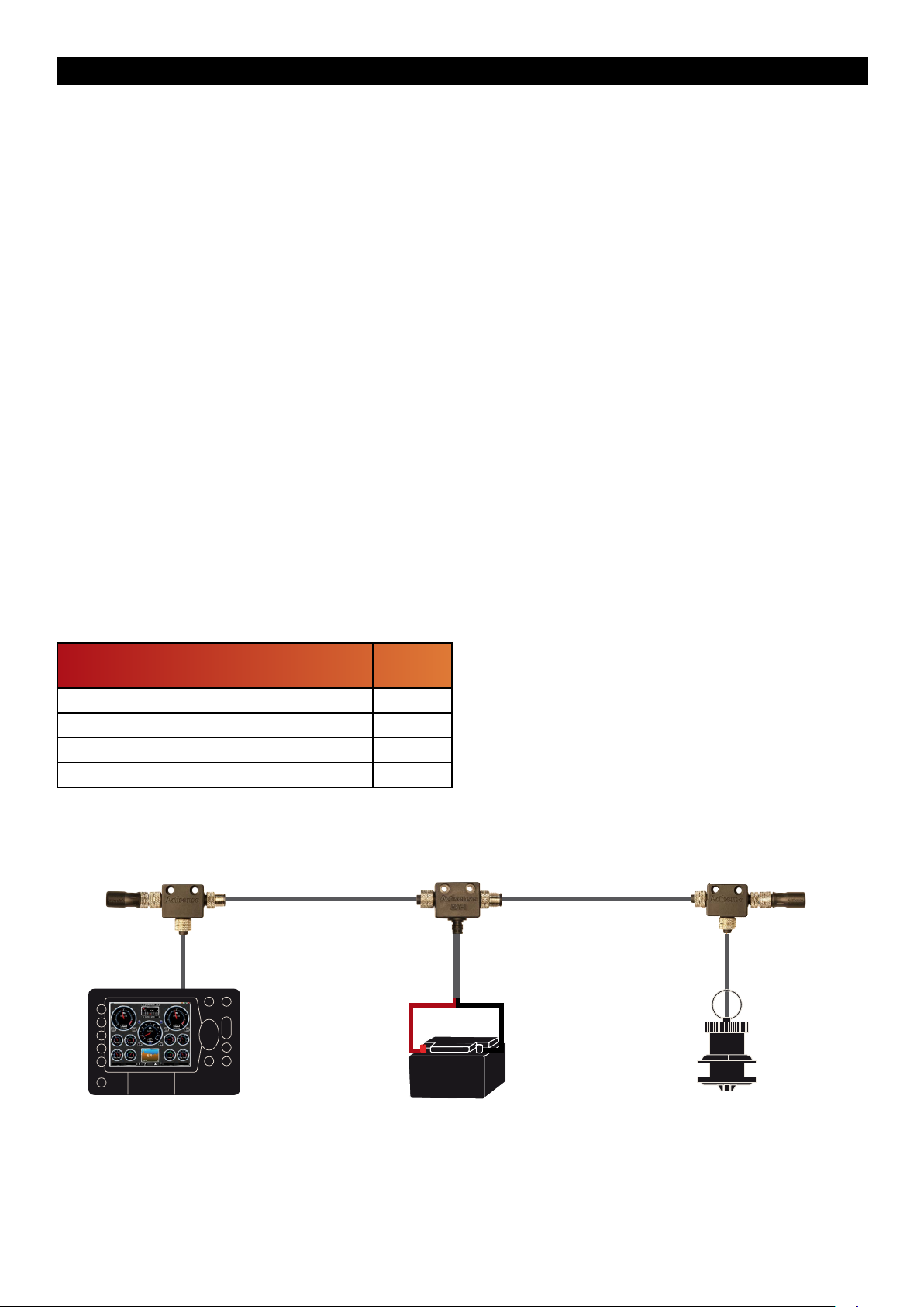
NMEA 2000 Minimum Network Requirements
All NMEA 2000 networks require a 12V DC supply.
In addition, a correctly functioning network will require the
following components :
• 1 x Power-T
• 2 x Terminating Resistors
• 2 x T-Pieces (one per connected device)
• 2 x NMEA 2000 Devices (such as the NGT-1)
All the required network parts can be supplied by the
Actisense A2K range.
Refer to “Figure 2 - NMEA 2000 Minimum Network
Requirements Diagram” for an example network. Note
that the diagram should not be used as an installation
guide. NMEA 2000 networks should only be installed
following the NMEA 0400 specication and all wiring
should be in accordance with the regional code of practice
for installations.
Figure 2 - NMEA 2000 Minimum Network Requirements Diagram
T-Peice
(A2K-T-MFF)
Terminator
(A2K-TER-M)
Power Tap
(A2K-MPT-1)
12v
Example Device Example Device
T-Peice
(A2K-T-MFF)
Terminator
(A2K-TER-F)
Page 9© 2015 Active Research Limited
Page 10
NGT-1
Do not
connect
Connecting the ISO cable
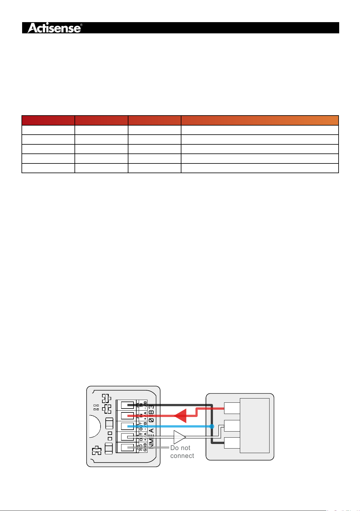
On the ISO variants of the NGT-1, a pre-tted four-core screened cable for connecting to a variety of devices. Actisense
ISO-Drive output circuitry and OPTO input circuitry allows many different types of device to be connected without the
need for conguration. Voltage levels are managed automatically as well as accepting both differential and ground
referenced connections safely. This allows connection to a standard RS232 PC port and the exibility to connect to an
RS422 system if required for an embedded application. “Table 2 - ISO Cable Connections” shows the cable
assignments used.
Table 2 - ISO Cable Connections
Wire Colour Wire Name PCB Label Connects To
Black Opto In B / - IN B / - RS232 ground or RS422 OUT negative
Red Opto In A / + IN A / + OUT positive
Blue ISO Out B / - OUT B / - RS232 ground or RS422 IN negative
White ISO Out A / + OUT A / + IN positive
Bare/Silver Ground ISO GND Not Connected
Connecting to an RS232 (PC) port
When connecting to a standard 9-pin RS232 serial PC
port, the cable and a connector must meet the following
specication:
4. Connect the IN -/B and OUT -/B together and connect to
the PC’s serial port ground (standard 9 pin D-type, pin 5).
1. A minimum of 3-cores are required in a shielded cable.
Higher quality cable will naturally yield higher performance/
higher Signal-to-Noise Ratio (SNR). Most typical cables
have two twisted pairs inside. In this case, use one pair for
the TX line and one for the RX line. Use the spare wire in
each pair as ground, and connect the cable shield to
ground only at the computer end.
2. A DB9 (9 pin D-type) type female (socket) connector for
the PC end of the cable.
3. The OUT +/A of the NGT-1 should be connected to the
RX of the computer (standard 9 pin D-type, pin 2) and the
NGT-1 IN +/A should be connected to the TX of the
computer (standard 9 pin D-type, pin 3).
Figure 3 - PC / RS232 Port Connections
Arrows indicate
direction of data ow
Note: To change the port number used in Windows refer
to “Windows Port Number Conguration”.
Note: Refer to “Status LEDs” on page 13 for LED
behaviour.
Note: Actisense supply a cable with the 9 pin connector
already tted, Actisense part ‘DB9-F’.
To t the DB9-F cable refer to “Connecting a Custom
Cable” on page 11.
Note: The NGT-1-ISO PCB is labelled ‘NMEA 0183’ on
the RS232 side as the PCB shares the same design with
the Actisense NGW-1-ISO
COMPUTER
TX
Pin 3
Personal
Computer
RX
( 9 PIN 'D'
Pin 2
RS232
Port)
GND
Pin 5
Page 10© 2015 Active Research Limited
Page 11
NMEA 2000 to PC Interface - NGT-1
NGT-1
Connecting a Custom Cable
The ISO/PC cable is connected inside the NGT-1 case to screw terminals. It is possible to replace the supplied cable
with a custom cable for different applications. A spare cable gland is supplied for strain relief and splash proong.
The NMEA 2000 cable is also connected using screw terminals. It is recommended that certied NMEA 2000 drop
cables are used to extend the existing cable rather than replacing it. The supplied grommet is not suitable for correctly
specied NMEA 2000 micro cable.
Opening the NGT-1 Case
To open a NGT-1 case, remove the two screws in the base
of the unit, then carefully lift off the top of the case. The
cable glands must be slid out from the top of the case in
order to access the internal connections. Pulling the lid off
too roughly without sliding the glands out may damage to
the cable connections. The NGT-1 circuitry will be left
attached to the base of the unit and the two supplied
cables attached to their connectors.
Custom ISO/PC Cable
The cable should have two shielded twisted pairs: one pair for the input and one pair for the output. The maximum
length of the cable is dependent on the input/output specications of the connected device and the cable quality. Using
an unsuitable cable may result in data loss. A spare cable grommet is supplied for strain relief and splash proong a
replacement ISO/PC cable.
Note: When opening an NGT-1 case, be aware that the
circuitry inside is not 100% protected against static
electricity. Please ensure that you use precautions against
static damage by only touching the connector block and
by holding the unit by its plastic base.
Note: Any damage caused to the unit while the case is
open is not covered by the guarantee.
Custom NMEA 2000 Cable
Replacement NMEA 2000 cable is required to conform in
full to the NMEA 2000 specication and be no longer than
6 metres (maximum drop length).
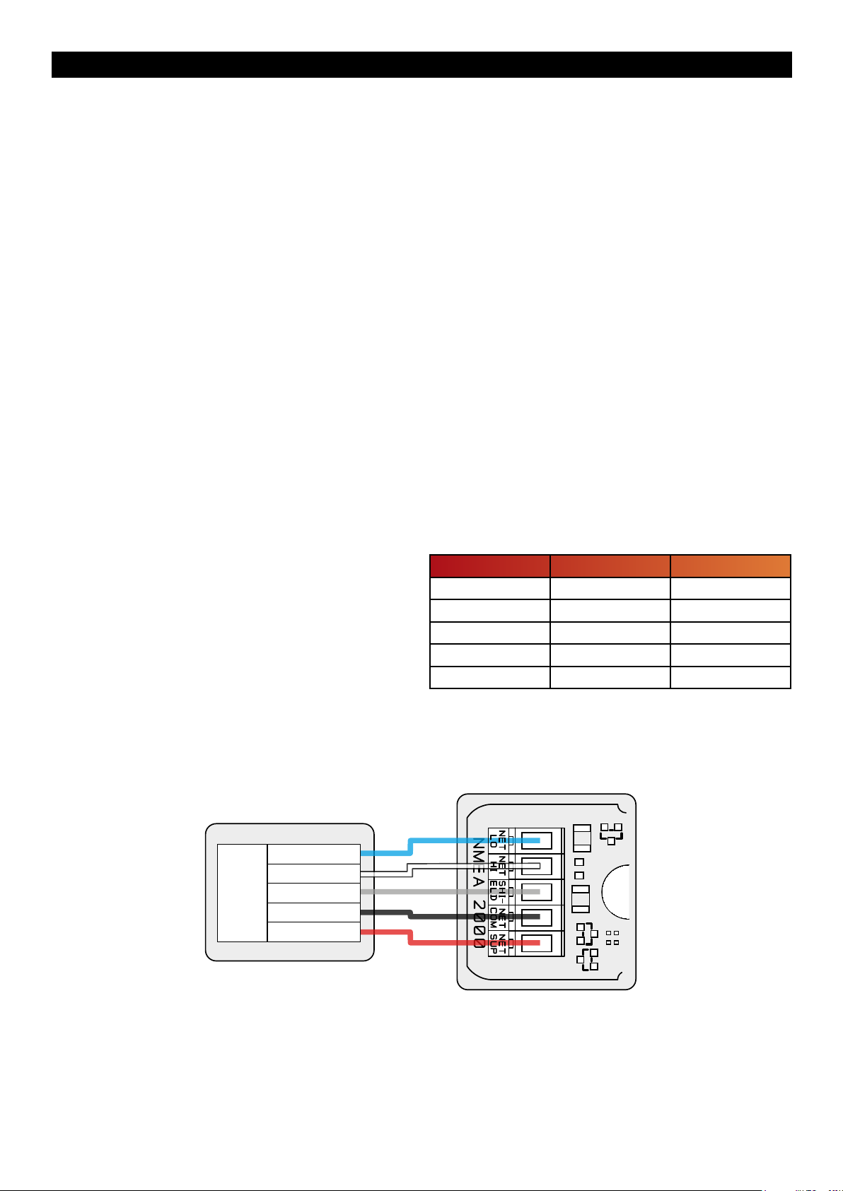
Refer to “Figure 4 - NMEA 2000 PCB Connections” and
“Table 3 - NMEA 2000 Connection Table”.
Note: The colours given relate to the supplied Actisense
cable and the NMEA 2000 standard cable denition.
Figure 4 - NMEA 2000 PCB Connections
NMEA 2000 Drop Cable
CAN Lo
CAN Hi
Shield
NET COM
CAN
Network
NET SUP
Table 3 - NMEA 2000 Connection Table
Wire Colour NMEA 2000 PCB Label
Bare/Silver Shield SHIELD
Blue Net Low NET LO
White Net High NET HI
Black Net Common NET COM
Red Net Supply NET SUP
Page 11© 2015 Active Research Limited
Page 12

Conguring the NGT-1
Conguration Requirements
It is the responsibility of the software application to congure the NGT-1 being used in order to meet its NMEA 2000
requirements. This means that the NGT-1’s conguration will be dependant on the software application’s last used
settings. It is possible to manually congure the NGT-1 using Actisense NMEA Reader, as long as it is understood that
any such modications could be lost when using the NGT-1 with another software application.
Connecting the NGT-1 to NMEA Reader
Connect the NGT-1 to the PC (by USB cable or RS232
cable depending on variant) and run the NMEA Reader
program. Select the port number for the NGT-1 and select
the Baud rate. The default Baud rate for the NGT-1 is
115200. NMEA Reader will attempt to communicate with
the NGT-1. Once successful the ‘Hardware Cong’ tab will
become available and the green LED indicator next to the
Baud selection will ash.
Note: The COM port must be opened at the baud rate the
NGT-1 is congured to use as there is no auto baud
feature in NMEA Reader. This will typically be 115200 or
230400 baud.
The ‘Hardware Cong’ tab shows the ‘Tx PGN Enable
List’, ‘Rx PGN Enable List’, ‘Serial Baud Rate’ and ‘ARL
P-Codes’ options”.
Selecting PGNs for transfer
The NGT-1 has two modes of operation: ‘Transfer: Normal’
and ‘Transfer: Receive All’. In the NGT-1 default ‘Transfer:
Normal’ mode, the PGNs that are received from the NMEA
2000 bus and transferred to the PC software application
are specied in the ‘Rx PGN Enable List’. Disabling a PGN
in the Rx list will stop its transfer to the PC.
Changing the Baud rate
The top ‘Serial Baud Rate’ drop down menu is used to
change the NGT-1 ISO/PC connection baud rate. The
bottom drop down menu is disabled as it is currently not
required. Select the new NGT-1 baud rate and click the
‘Apply’ button. The new conguration will be sent to the
NGT-1, forcing a reboot so the new baud rate can be
enabled. NMEA Reader will re-open its COM port to the
new baud rate to continue communication with the NGT-1.
Refer to the log tab to conrm the reboot and reconnect
process has completed before attempting to edit any
further conguration options.
Note: Do not make any other conguration changes when
setting the Baud rate. Some changes may be lost when
setting the new Baud rate.
Note: Only USB variants of the NGT-1 are capable of
operating at baud rates above 115200. Do not change the
baud rate of ISO variants above 115200, as doing so will
prevent the NGT-1 from communicating and may require
the device be ‘returned to base’ for reconguration.
Note: Changing the baud rate to less than 115200 Baud
may result in some NMEA 2000 PGN messages being lost
due to overloading.
However, by default many software applications (including
NMEA Reader) will put the NGT-1 in to ‘Transfer: Receive
All’ so that all NMEA 2000 PGNs can be transferred to the
PC software application. In this mode, the ‘Rx PGN Enable
List’ is not used and any user modications to it will not
result in any change of the NGT-1’s behaviour.
The PGN Enable Lists can be refreshed with the NGT-1’s
current values using the ‘Update from hardware” button
and reset back to the factory defaults using the ‘Apply
defaults to hardware’ (there is no need to press the ‘Apply’
button to complete this operation).
Special ARL P-codes
The ‘ARL (Active Research Ltd.) P-codes’ option enables/
disables transmission of special proprietary messages
from the NGT-1 to the PC. There should not be any reason
to disable this in an NGT-1, however if required to select
the new behaviour and click the ‘Apply’ button.
Page 12© 2015 Active Research Limited
Page 13
NMEA 2000 to PC Interface - NGT-1
Troubleshooting Guide
This guide will concentrate on all relevant troubleshooting issues, that may arise on your NGT-1. Therefore, the cables
between the NGT-1 hardware and any other devices should be checked as a matter of course, before continuing with
this guide.
Status LEDs
The NGT-1 hardware has two bright LEDs that can be seen through the case to indicate when data is received from
either the serial device or NMEA 2000 network connection. It is an important point to note that these two LEDs can only
show when their respective data is RECEIVED; it is not possible to show both transmit and receive simultaneously on a
single colour LED.
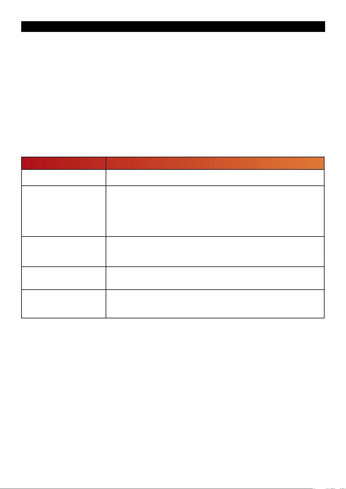
These LEDs can be used to debug potential problems using the ‘Behaviour’ and ‘Solution’ details in Table 4 using
NMEA Reader as a diagnostics tool.
Figure 5 - Diagnostic LED
Behaviour Solution
USB only: The LEDs do not
light
The NMEA 2000 LED does not
ash when the NMEA 2000
network is active
The serial LED does not ash
when connected to a PC
software application
Both LEDs ash together, once
every 10 seconds
The LEDs ash alternately very
fast (4 times per second). This
sequence repeats continuously
The USB driver has not been installed correctly, refer to “USB Driver Installation”
on page 8
Check that the NGT-1 is connected to the NMEA 2000 network and that the NMEA
2000 network is operational refer to “Connecting to an NMEA 2000 Network” on
page 9.
Conrm that at least one periodic PGN message is being sent on the NMEA 2000
network and there are at least two NMEA 2000 devices on the network. If another
NGT-1 is available, NMEA Reader can be used to prove the status of the NMEA
2000 network.
Check that the NGT-1 is connected correctly to the PC (via USB or RS232 port)
and the software application has opened the COM port connected to the NGT-1 at
the matching baud rate. Refer to the relevant connection option from those
described on page 8 onwards.
Indicates that the NGT-1 is powered but no data is received from either connection.
If valid data should be present and transferred by the NGT-1 on one or both inputs,
refer to the two rows above.
Indicates that the NGT-1 has lost its Firmware, please connect the unit to the latest
NGT-1 Actipatch and re-install the Firmware. The latest Firmware can be found on
the NGT-1 downloads web page.
Technical Support and the Returns Procedure
All installation instructions and any warnings contained in this manual must be followed before contacting Actisense
technical support. If the troubleshooting guide did not help resolve the problem and an error persists, please contact
Actisense technical support to help trace the issue before considering the return of the product. If Actisense support
concludes that the NGT-1 unit should be returned to Actisense a Returns Number will be issued by the support engineer.
The Returns Number must be clearly visible on both the external packaging and any documentation returned with the
product. Any returns sent without a Returns Number will incur a delay in being processed and a possible charge.
Page 13© 2015 Active Research Limited
Page 14
Specications
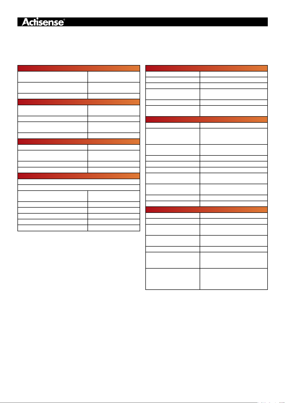
Table 4 - Specication Table
Power Supply (ISO Variant)
Supply Voltage
(NMEA 2000 Port)
Supply Current
(NMEA 2000 Port)
LEN 1
Power Supply (USB Variant)
Supply Voltage
(NMEA 2000 Port)
Supply Current (USB Host Port) 85mA @ 5V DC
Supply Current
(NMEA 2000 Port)
LEN 1
Mechanical
Housing Material Lid Polycarbonate
Housing Material Base
Weight NGT-1-ISO 220g
Weight NGT-1-USB 210g
Approvals and Certications
Fully NMEA 2000 Certied
Meets all IEC 61162-3 requirements
EMC
Environmental Protection IP54
Operating Temperature -20°C to +55°C
Storage Temperature -30°C to +70°C
Recommended Humidity 0 - 93% RH
Guarantee 3 years
All specications are taken with reference to an ambient temperature
(TA) of +25°C.
9.5 to 35V DC
35mA @ 12V DC
Max 50mA
9 to 29V DC
15mA @ 12V DC
Max 50mA
Flame retardent ABS
(UL V-0)
IEC 60945
(Sections 9,10, & 11.2)
NMEA 2000 Port (All Variants)
Compatibility Fully NMEA 2000 certied
Galvanic Isolation Refer to 'PC port' or 'USB port'
Speed / Baud Rate 250kbps
Connectivity
Cable Length NMEA 2000 1.5m
Cable Length STNG
Adapter
PC Port (ISO Variant)
Compatibility Full RS232 & RS422 compatible.
Galvanic Isolation
Speed/Baud Rate
Output Voltage Drive >= 2.1V (differential) into 100Ω
Output Current Drive 20mA max.
Output Protection Short circuit and ESD
Input Voltage Tolerance
Input Protection
Connectivity 5mm stripped and tinned wire
Cable Length 1.5m
USB Port (USB Variant)
Compatibility USB 1.1, 2.0 and 3.0
Galvanic Isolation 2500V input to ground
Speed / Baud Rate
Connectivity
Cable Length 1.5m
Drivers (Latest OS)
Drivers (Legacy OS)
M12 Male (A polarised) connector
moulded on cable
0.4m (1.9 with NMEA 2000 cable
connected)
2500V input to ground
1500V output to ground using
ISO-Drive
4800 to 115200 Baud
Default setting - 115200 Baud
-15V to +15V continuous -35V to
+35V short term (< 1 second)
Current limited and overdrive
protection to 40V DC
4800 to 230400 Baud
Default setting - 115200 Baud
Male type A plug moulded onto
cable
Windows XP, Vista, 7, 8, 8.1 &
MAC OS X supplied on CD & via
the NGT-1 downloads web page.
Contact Actisense for full details
of the legacy OS versions
supported support@actisense.
com
Page 14© 2015 Active Research Limited
Page 15
NMEA 2000 to PC Interface - NGT-1
Minimum NMEA 2000 PGN List
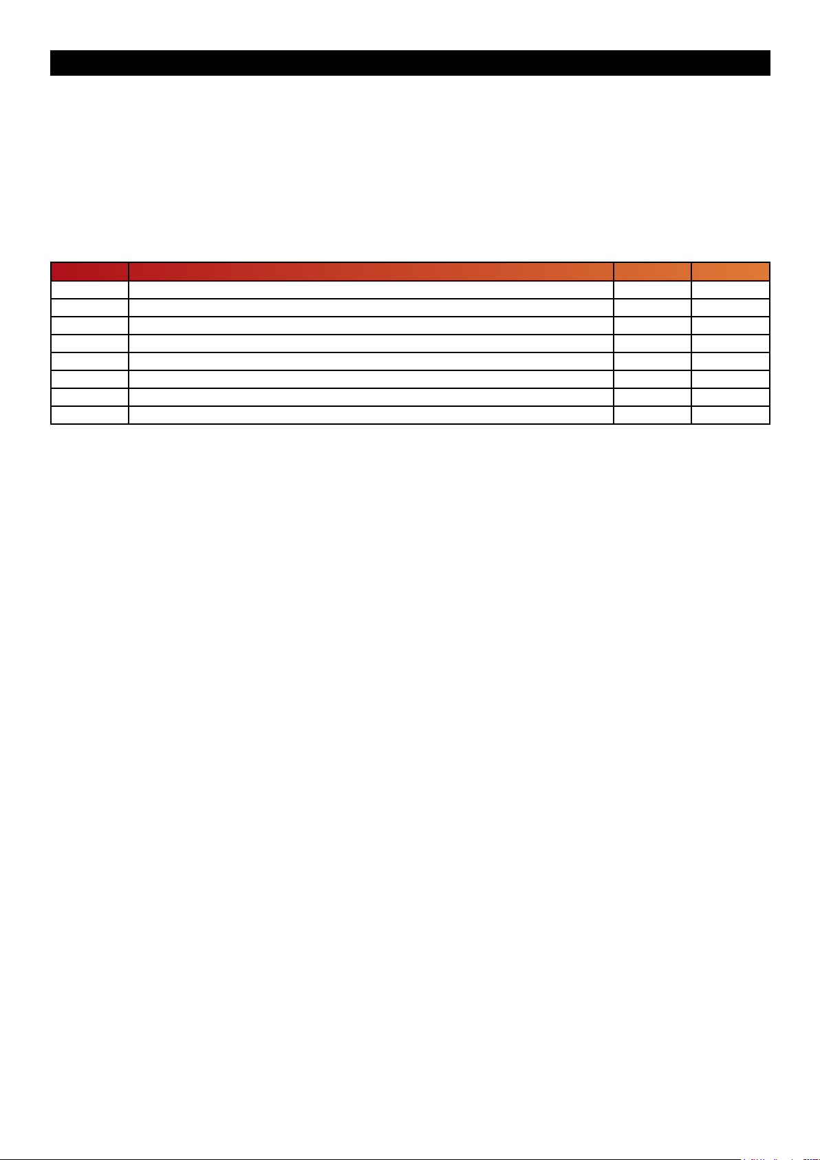
The NGT-1 is capable of transferring any PGN in the NMEA 2000 specication to or from the NMEA 2000 bus depending
on the conguration of the NGT-1. Optionally, the NGT-1 can be put in “Transfer: Receive All” mode, which allows the
NGT-1 to transfer any and all PGN messages from the NMEA 2000 bus without limitation. It is impractical to publish the
entire NMEA 2000 PGN list, “Table 5 - Minimum NMEA 2000 PGN List” shows the PGN messages that cannot be
disabled by software conguring.
Table 5 - Minimum NMEA 2000 PGN List
PGN PGN Name Rx Tx
59392 ISO Acknowledge NO YES
59904 ISO Request YES NO
60160 ISO Transport Protocol, Data Transfer YES YES
60416 ISO Transport Protocol, Connection Management YES NO
60928 ISO Address Claim NO YES
65240 ISO Address Command YES NO
126208 NMEA - Request Group Function YES NO
126464 PGN List (Tx List and Rx List) NO YES
Page 15© 2015 Active Research Limited
Page 16
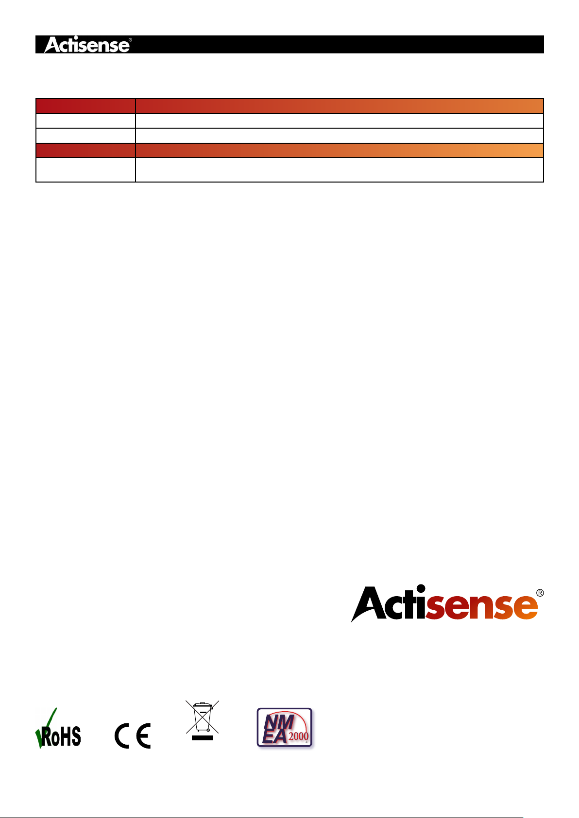
NGT-1 Product Order Codes
Product Code Product Description
NGT-1-ISO NMEA 2000 PC Interface, special version with RS422 serial
NGT-1-USB NMEA 2000 PC Interface, standard version with USB
STNG-A06045
SeaTalkNG to NMEA 2000 adaptor cable (drop). Only for purchase with Actisense NMEA
2000 devices
Active Research Ltd
Unit 5, Wessex Trade Centre
Ringwood Road
Poole, Dorset
UK, BH12 3PF
Telephone: +44 (0)1202 746682
®
Email: [email protected]
Web: www.actisense.com
Page 16© 2015 Active Research Limited
 Loading...