

Page 1
OWNER’S MANUAL
IRONMAN MOJAVE MASSAGE TABLE
Model # 9105
Page 2

TABLE OF CONTENTS
P
age #
Warning label placement 3
Safety precautions 5
Overview drawing 6
Part list 7
Assembly 8
Storage 12
Transport the table 12
Maintenance instructions 13
ytnarraW 14
01 tnemtsujdA
www.ActiveForever.com
2
Page 3
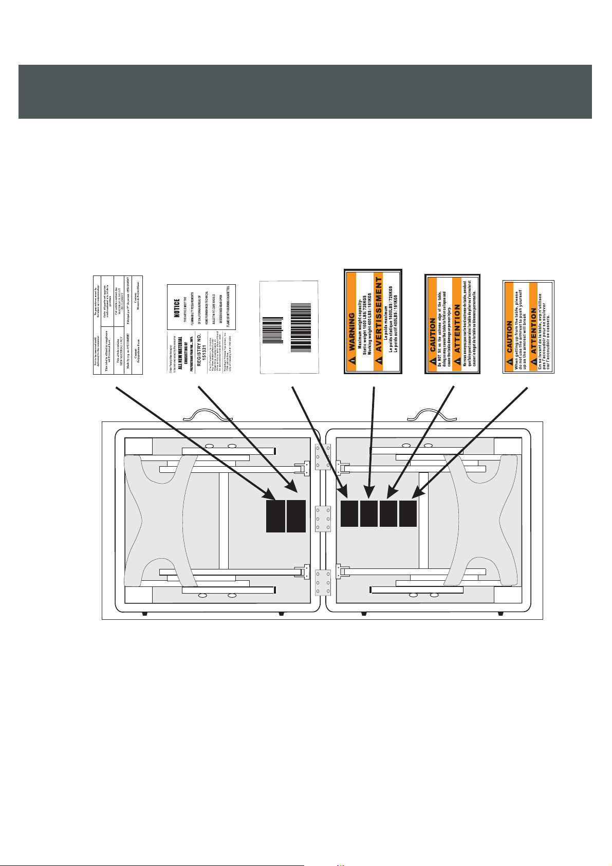
WARNING LABEL PLACEMENT
0
09105
90598
8
Serial No.: 18081910500001
MADEIN CHINA/ FABRIQUEEN CHINE
18081910500001
3
Page 4

SERVICE
To request for product service and order replacement parts, please call our
customer service department at
1-866-924-1688
Monday through Friday, 8:00 am-5:00 pm Pacific Standard Time,
or email at:
service@paradigmhw.com
Please have the following information ready when requesting for service:
Your name Phone number Owner’s manual
Model number Serial number Part number
Date of Purchase
*If the product has major defects which prevent it from functioning
properly, please return it to the store of purchase within the period
allowed by the store.
Paradigm Health & Wellness, Inc.
1189 Jellick Ave.
City of Industry, CA 91748
4
Page 5

SAFETY PRECAUTIONS
(1) Maintain the table periodically. Make sure all screws are secure and the cable has not
deteriorated or frayed. Make sure there are no cracks in the wood structure.
(2) Do not overload the table beyond the recommended weight limit. This could result in
serious injury to the user.
(3) Do not use alcohol based cleaners when cleaning the vinyl. This could cause damage
to the vinyl material. Use warm soapy water and wipe dry.
(4) Make sure when using the table that all four legs are at the same level. Using the legs
at different levels can cause the table to be unstable and cause injury.
(5) Maximum weight capacity- static weight: 2200lbs/998kgs
working weight: 550lbs/250kgs
5
Page 6

OVERVIEW DRAWING
18
32
1
16
17
33
35
29
30
23
23
12
14
7
16
19
11
27
28
22
10
22
21
24
4
5
28
34
15
25
29
23
23
30
19
11
28
27
22
25
9
8
31
28
20
12
7
16
21
10
8
22
31
26
26
8
31
22
22
21
10
28
31
14
8
28
20
9
31
25
19
23
27
12
13
13
5
28
29
19
22
22
10
25
30
23
11
27
31
6
13
2
31
6
3
24
23
23
30
12
11
21
28
14
7
16
29
15
14
7
16
6
Page 7

PART LIST
Part#
001 Front Bed with Frame 1 019 Short Cable 4
002 Rear Bed with Frame 1 020 Long Cable 2
003 Upper Buckle 2 021 M6x70mm Self Tapping Bolt 4
004 Lower Buckle 2 022 Plastic Washer Ø13xØ6x2t 16
005 Handle 2 023 Plastic Washer Ø15xØ6x4t 12
Desc
ription
Quan.
Part#
Desc
ription
Quan.
006 Rubber Foot 4 024 M3x20mm Round Head Self
Tapping Screw
007 Lower Leg End Cap 4 025 M6 Nylon Nut 4
008 Long Brace 4 026 M6x75mm Bolt 4
009 Cross Brace 2 027 M6x75mm Self Tapping Bolt 4
010 Short Brace 4 028 Plastic Washer Ø18xØ6x2t 12
011 Upper Leg 4 029 M4x18mm Mod. Truss Head
Screw
012 Lower Leg 4 030 M6x90mm Bolt 4
013 Hinge 3 031 M4x20mm Self Tapping Screw 30
014 Leg Knob 4 032 U Shape Headrest 1
015 End Panel 2 033 Armrest 1
016 M4x20mm Round Head Self
Tapping Screw
017 Headrest Bushing Plate 1 035 1/4"x25.5mm Bolt 4
018 Face Cushion 1
7 034 Armrest Tube 2
10
20
7
Page 8

1
ASSEMBLY
Unlace the Buckles and then open the table so
that it is standing on the Rubber Foot side.
Take out the Face Cushion, U Shape Headrest,
and Armrest from underneath of the table.
2
3
Pull out the left and right pair of Legs and
straighten each joint.
Lift the table up until all four legs are on the
floor.
8
Page 9

4
5
ASSEMBLY
Lift one end of the table and pull out to open
table fully.
6
Insert both Right/Left Headrest Sticks with
Headrest into the holes of the Headrest
Bushing Plate.
Place the Face Cushion onto the U Shape
Headrest with the designated velcro stickers.
WARNING: HEADREST IS FOR LIGHT
RESTING ONLY! PLEASE DO NOT ADD
HEAVY PRESSURE WHEN RESTING.
9
Page 10

7
ASSEMBLY
Insert the Armrest Tubes into the holes on the
Upper Legs.
ADJUSTMENT
Adjusting the angle of the Headrest
Pressing up the Locking Handles and then
adjust the Headrest to the desired angle.
Pressing down the Locking Handles after
adjustment.
Adjusting the Table Height
Lay the table on the Rubber Foot side and then
remove the Leg Knob.
10
Page 11

ADJUSTMENT
Adjusting the Table Height
Remove the Lower Leg and then place the
Lower Leg back onto the Upper Leg to the
desire hole for adjusting the height of the table.
Tighten the Leg Knob after adjustment.
NOTE: Adjust all of the four Legs to the
same height.
11
Page 12

STORAGE
1. Lay the table on its side and fold at an angle.
2. Completely fold the Legs flat under the table. able.
3. Make sure the Cables, U Shape Headrest, Face Cushion, and Armrest are
3. Make sure the Cables, U Shape Headrest, Face Cushion, and Armrest are
inside the table before closing it.
inside the table before closing it.
TARNSPORT THE TABLE
The table is easy to carry with the shoulder strap of carry bag. The table is easy to carry with the shoulder strap of carry bag.
12
Page 13

MAINTENANCE INSTRUCTIONS
You should check your massage table for any kind of wear and tear before each use.
1. Check the legs, beds, cables for wear and tear.
2. Replace damaged and worn components immediately.
3. Keep all damaged equipment out of use until it is repaired.
13
Page 14

WARRANTY
Paradigm Inc. warrants to the original purchaser that this product is free from defects
in material and workmanship when used for the purpose intended, under the
conditions that it has been installed and operated in according to Paradigm’s Owner’s
Manual. Paradigm’s obligation under this warranty is limited to replacing free of
charge, any parts which may prove to be defective under normal home use. This
warranty does not include any damage caused by improper operation, misuse or
commercial application. From the date of purchase, the frame is warranted to be
free from defects for 1 (one) year. All parts and workmanship, including electronics
and its console cases, upholstery, foam, ball bearings, pulleys, cables, shocks, all
tension mechanisms, wheels, pedals and hardware are to be free from defects for 90
days. This warranty is offered only to the original owner and is not transferable.
Proof of purchase is required.
14
 Loading...