

Page 1

NMEA Buffer
NBF-2-A
User Manual
Issue 1.03
1 Galvanically opto-isolated NMEA 0183 “Listener” data input
for complete isolation of the input from ground, meeting all
the specications of the latest NMEA 0183 / IEC61162-1&2
specications.
6 ISO-Drive “Talker” outputs, compatible with both NMEA 0183
(RS422 / RS485) and RS232 listeners.
Compatible with NMEA 0183 standard and “HS” (AIS) baud rates,
and speeds well in excess of this for special applications.
Page 2

Page 3

NMEA Buffer - NBF-2-A
Contents
Important Notices 4
Notices 4
Foreword 4
Introduction 4
NMEA 0183 Introduction 5
Electrical specications 5
Technical features 5
Connecting devices together 6
The basics 6
The NMEA signals 6
The different NMEA standards 6
Connections 7
Input Connections 8
NMEA 0183 Input 8
Connecting to the battery supply 8
Output Connections 9
NMEA 0183 / RS422 Outputs 9
Troubleshooting guide 10
Specications 11
Company Information 12
Page 3© 2009 Active Research Limited
Page 4

Important Notices
Actisense and the Actisense logo are registered trademarks
of Active Research Limited. All rights are reserved. The
contents of this manual may not be transferred or copied
without the expressed written permission of Active
Research Limited. All other trademarks are the property of
their respective owners.
The Actisense NMEA Data Buffer (NBF-2) is intended for
use in a marine environment, primarily for below deck use.
If the unit is to be used in a more severe environment,
such use may be considered misuse under the seller’s
warranty.
The NBF-2 has been certied to comply with the European
directive for Electro-Magnetic Compatibility (EN60945),
and is appropriately CE marked. Operation of the unit
should be in conjunction with appropriate CE approved
shielded connectors and cabling used in accordance with
the CE directive EN60945. Any EMC related issues should
be reported to Active Research immediately to allow the
company to rectify or resolve EMC related problems in
accordance with its obligations under EN60945.
Foreword
Actisense recognises that instructions are often skipped,
so we have aimed to write this document in an informative,
yet direct manner that will aid the user. We have tried
to cover all the points a typical user may need to know.
Please read all sections before installing and using the
Actisense NMEA Buffer product and any related software
programs.
Introduction
The Actisense NMEA 0183 Buffer (NBF-2) product was
developed to solve a common problem: wanting to share
the NMEA information from an NMEA device with more
than two other NMEA instruments. Most NMEA output’s
(e.g. GPS) can only drive 1 or 2 NMEA devices, any more
and the signal becomes degraded and corruption of the
NMEA data occurs.
The Actisense NMEA Buffer solves all NMEA buffering
problems by allowing distributed buffering of one NMEA
instrument’s data output to a large number of other NMEA
device inputs, and if required, even a PC’s RS232 port.
If the unit is connected such that compliance failure occurs
beyond the company’s control, the company shall not be
held responsible for compliance failure until suitable EMC
guidelines for connection are seen to have been taken.
Notices
When using this document, keep the following in mind:
The products described in this manual and the specications
thereof may be changed without prior notice. To obtain upto-date information and/or specications, contact Active
Research Limited or visit the Actisense website (www.
actisense.com).
Active Research Limited will not be liable for infringement
of copyright, industrial property right, or other rights of a
third party caused by the use of information or drawings
described in this manual.
Active Research Limited will not be held responsible for
any damage to the user that may result from accidents
or any other reasons during operation of the user’s unit
according to this document.
Utilising fourteen years of experience in the marine
industry in creating market leading depth sounders and
other NMEA products, Actisense recognised the need to
produce a full galvanic Opto-isolated, dependable NMEA
buffering solution that meets, and indeed surpasses, all of
the NMEA 0183 requirements.
Full information on the complete Actisense product range
can be found on the Actisense website.
The NBF-2 does not validate the NMEA data it receives
in any way. Neither the NMEA sentence checksum, nor
the data contained within the NMEA sentence is validated.
Therefore, the electronic device(s) supplying the NBF-2
with NMEA data retain(s) the sole responsibility for the
NMEA data’s validity.
Page 4© 2009 Active Research Limited
Page 5

NMEA 0183 Introduction
NMEA Buffer - NBF-2-A
Designed over 20 years ago, the NMEA 0183 standard
has slowly become the common method by which marine
electronics devices talk to one another. The standard
species both the electrical connections that make up an
NMEA system and the format of the data sentences that
carry the NMEA information.
The NMEA 0183 standard is a purely digital data
transmission scheme, using ‘1’s and ‘0’s in a binary format,
to communicate a digital representation of the required
information (depth, speed etc.) to connected instruments.
Electrical specications
The latest specications for NMEA 0183 (version 2
onwards) are similar to the RS422 standard. They use
+5v and 0v signalling, which is low voltage and can be
interfaced to computer equipment (with an Actisense
Opto-isolated adapter cable). In older equipment
(version 1) however, voltage levels could be much greater
(up to +/- 15v) as the original specication used 12-15
volt +/- signalling, which is similar to the standard RS232
computer serial communication ports.
The NMEA 0183 specication also requires that all
receiving equipment must be Opto-isolated; this Opto-
isolation requirement reduces the chances of interference
and removes the problem of ground loop effects.
Wide battery input voltage range to offer maximum
compatibility, the NBF-2 can operate from a battery supply
anywhere between 8 and 45 volts.
Very low power consumption that is typically 43mA with
no load and 100mA with all 6 outputs maximally loaded
(on a 12 volt system). This will reduces to 25mA and 50mA
respectively on 24 volt systems.
Very tough Polycarbonate case is certied to IP66
(classied as “totally protected against dust and protection
against low pressure jets of water from all directions”).
Being Polycarbonate, it is also incredibly strong, offering
a wide temperature range and superior protection to the
electronics inside.
The IP66 rating of the case is only limited by the sealing
gasket strip, which can be enhanced by applying a suitable
non-acid based marine sealant to the gasket after wiring
and testing. This will allow use of the unit in areas where
salt spray could enter, accidental immersion may occur,
or in environments where maximum long-term reliability is
paramount.
Robust Nylon grommets are certied to IP68 (classied
as immersible for long periods without water ingress). Note
that to achieve this level of water integrity all grommets
must be occupied by round-section cables.
Technical features
The NMEA 0183 input is a galvanically opto-isolated
differential input to fully comply with the NMEA 0183
standard specication. This allows the input to work
correctly with long cable runs and in a noisy environment.
Typical operating voltage is 2.0v to 15.0v. The unit can
withstand +/- 35v continuously, and +/- 40v transients. The
Opto-isolator can protect any upstream equipment (chart
plotter, laptop PC, radar etc.) from up to 2500v of common
mode voltage difference.
Removes all problematic ground loops between the
NMEA device connected to the NBF-2 input port, and all
the NMEA devices connected to the output ports.
The NBF-2 is equipped with 6 ISO-Drive outputs. ISODrive output technology creates a driver, unique to
Actisense, that is isolated to 1500 volts. ISO-Drive creates
a completely oating talker output, making safe connection
to a PC an easy task.
The output automatically changes between differential and
single ended drive depending upon the type of instrument
it is connected to. The ISO-Drive output is fully compliant
with the NMEA 0183 standard specication and is also
compatible with RS232 signal levels.
Large range of possible cable diameters of between
4.5 mm and 10 mm, single or multi-pair wire types can be
easily accepted.
Page 5© 2009 Active Research Limited
Page 6

Connecting devices together
The basics
NMEA data is transmitted from an information source such
as GPS, depth sounder, gyro compass etc. These data
sending devices are called “Talkers”.
Equipment receiving this information such as a chartplotter, radar or NMEA display is called a “Listener”.
Unfortunately, only one Talker can be connected on to a
single NMEA 0183 system at any one time. Two or more
Talkers are simply not possible because they are not
synchronised to each other, and will attempt to ‘talk’ at
the same time (over each other), resulting in corruption of
the NMEA data, and potentially in disaster if valuable data
such as navigation information is lost or corrupted so that
it is incorrect and/or misleading.
This fundamental problem with the NMEA system can be
easily overcome, and multiple Talkers connected together,
using the Actisense NMEA Data Multiplexer “NDC” series
of instruments. If the required system has multiple NMEA
Talker device of the same type (e.g. two GPS units), the
highest priority device can be automatically switched using
the Actisense Autoswitch (NSW-1).
Please visit the Actisense website for full details on these
and other Actisense products.
This connection method is referred to as “single ended”
instead of the “differential” method used by NMEA 0183
v2.0 devices.
The data format is largely the same between both
systems, with v2.0 adding some extra sentence strings,
and removing older (redundant) sentence strings from the
specication. The situation is further complicated, as many
manufacturers still use the old (“single ended”) method of
connection because it is cheaper to implement.
So how can an older type NMEA device be connected to a
newer type device?
Care is needed – it is possible to damage or overload
the output of a newer differential device if it is incorrectly
connected to an older device. This is because the older
devices used ground as the return, whereas the newer
devices actually drive the NMEA “-/B” line between 5v and
0v. Thus, connecting this output to ground will result in high
currents being drawn by the driver instrument, resulting in
potential overheating and damage to the driver circuits.
To connect a new type differential device to an old type
single-ended system, connect the NMEA “+/A” output from
the differential driver to the single-ended NMEA “Rx” or “In”
input of the device. Leave the NMEA “-/B” output oating.
Connect the ground line of the differential output device to
the ground of the single-ended device. This provides the
required data signal return current path.
The output drive capability of many instruments means
that often their NMEA outputs can only drive one or two
Listeners. In this case, the output of the Talker can be
boosted to ‘talk’ to six listeners simultaneously using the
Actisense NMEA Buffer.
The NMEA signals
The NMEA 0183 system v2.0 and later uses a ”differential”
signalling scheme, whereby two wires are used to transmit
the NMEA data. These connections will be labelled as
either NMEA “A” and “B“ or NMEA “+” and “-“ respectively,
depending on the instrument and manufacturer.
When connecting between different manufacturers, there
can be some confusion, but it is simple and easy to
remember: NMEA “A” connects to NMEA “+” and NMEA
“B“ connects to NMEA “-“.
The different NMEA standards
The NMEA 0183 specication has slowly evolved over the
years, so connecting one device to another is not always a
straight forward matter. The earlier versions of NMEA 0183
(before v2.0, as detailed above), used slightly different
connection methods and signal levels: the instruments
had just one “NMEA” data line (‘Tx’ or ‘Out’), and used
the ground as the other line - similar to the way a computer
serial port works.
To connect an old type single-ended device to a new type
differential device, connect the NMEA ”Tx” or “Out” output
from the single-ended driver to the differential NMEA
“+/A” input of the device. Connect the ground line of the
single-ended output device to the NMEA “-/B” input of the
differential device. This provides the data signal return
current path. If the NMEA “-/B” input is left oating, then
data corruption / errors may occur.
The Actisense NBF-2 is equipped with ISO-Drive outputs
which removes all of these problems. Because the ISODrive output “oats”, this means that it will automatically
adjust to the voltage of the line it is connected to. Thus, it
simplies installation work, as you no longer need to check
on the type of input used on the equipment that the NBF-2
is connected to. You can connect the “B/-” connection of
the NBF-2 to ground or to a differential “B/-” input without
worry - the voltage levels will simply adjust themselves to
be correct.
Please refer to the Output Connections section for
example of these connection methods.
Page 6© 2009 Active Research Limited
Page 7
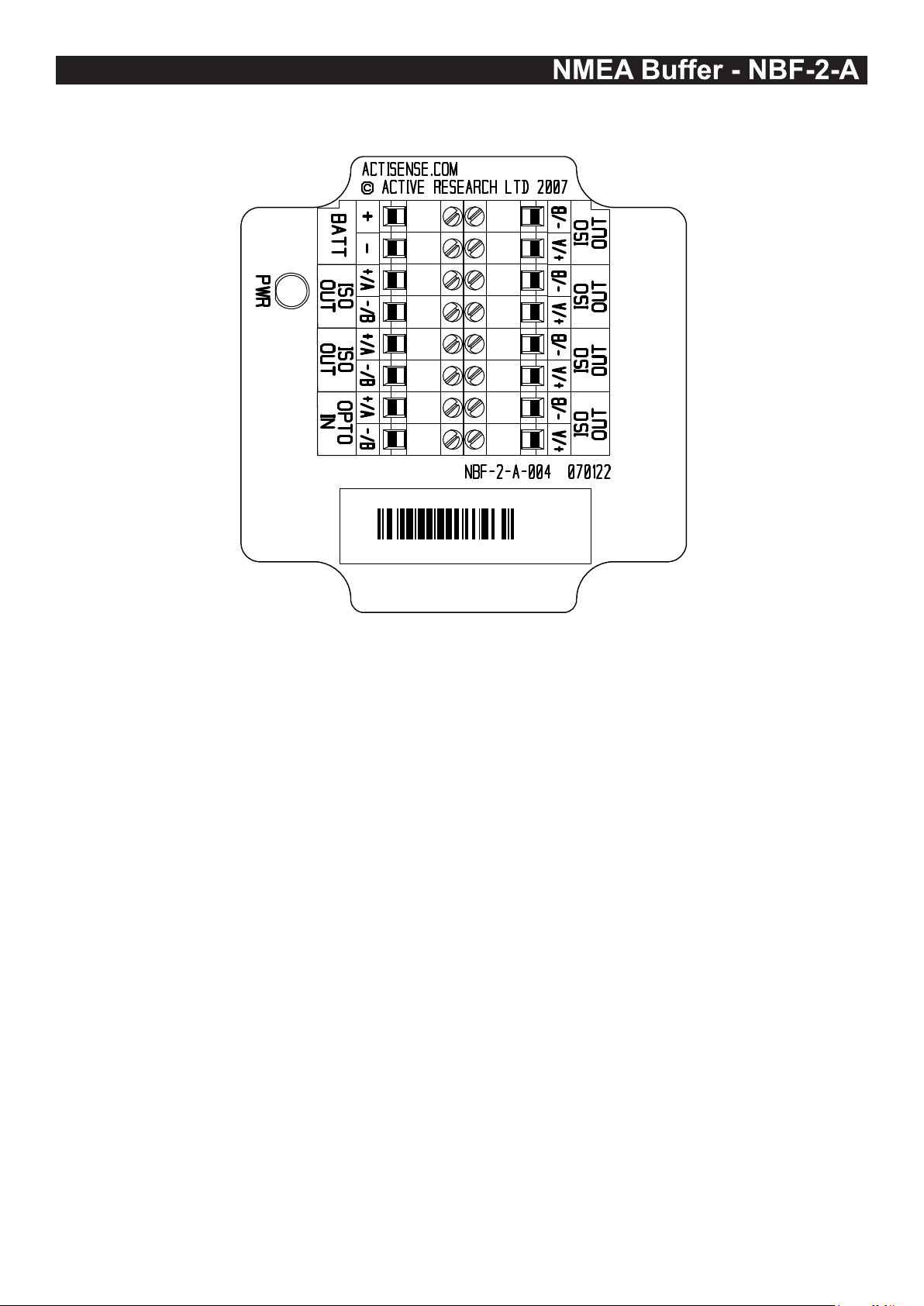
Connections
NMEA Buffer - NBF-2-A
NMEA BUFFER
99999
Figure 1 – All external connections
The NMEA Buffer (NBF-2) has screw-terminal “Phoenix” type external connections for: -
1. An NMEA 0183 “Listener” port
The NMEA 0183 input is of the differential optoisolated type and uses the unique Actisense low
current drain circuitry (2mA @ 2.0v) to conform in full
with the NMEA 0183 marine electronic device network
communication standard, and is exible enough to
interface to most full and partially compliant devices.
2. Six ISO-Drive “Talker” ports
Each output comprises of two connections: ‘+/A’
and ‘-/B‘, and conforms in full to the NMEA 0183
standard, and can be connected safely to NMEA
0183 v1,2,3,HS RS-232, RS-422 and RS-485 type
listeners.
3. Battery supply input.
NBF-2-A
Note:
1. To complete the NMEA 0183 standard all device
interconnection NMEA cables used should meet the
two-conductor, shielded, twisted pair conguration
specication. The shield connection of these wires
should be connected at the instrument end only to
prevent ground loops.
2. Refer to the Specications section for the full details
on input/output specications.
3. If the laptop / PC to be used with the NBF-2 does not
have an RS232 serial port available, the Actisense
USG-1 USB to Serial Gateway and the USB-1 USB
to RS232 adapter cable have been tried and tested
to provide a compatible communications port. Please
visit the Actisense website for full details on this,
and other Actisense products.
4. Higher quality cable will naturally yield higher
performance / higher Signal-to-Noise Ratio (SNR).
Page 7© 2009 Active Research Limited
Page 8
NBF-2-A
NMEA BUFFER
Input Connections
99999
+
Battery /
Power Supply
-
+
-
NMEA
Talker A
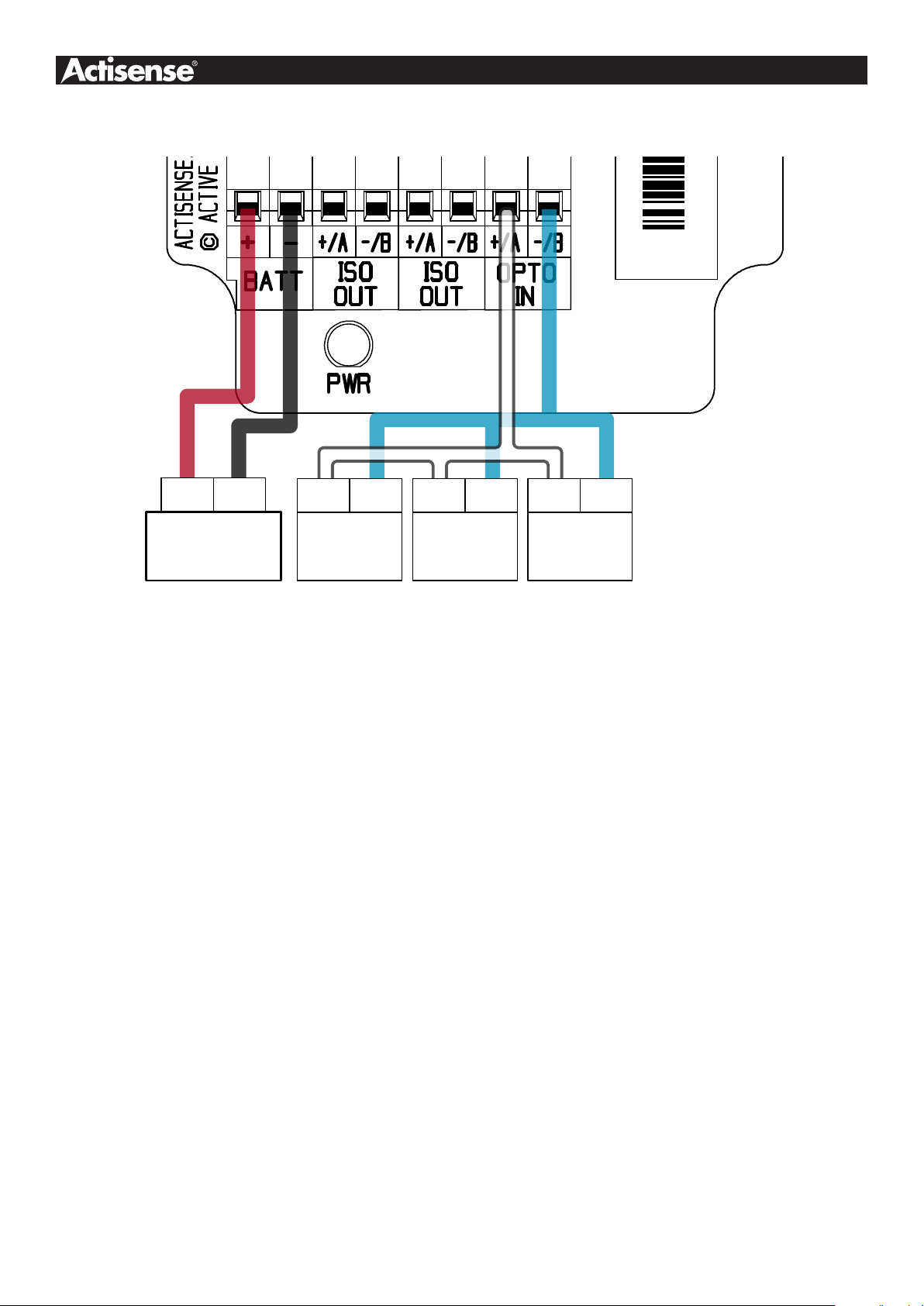
Figure 2 – Input connections
+
NMEA
Talker B
NMEA 0183 Input
The NMEA 0183 differential opto-isolated input is designed
to handle a variety of NMEA 0183 talker specications.
Please determine (from device manufacturer’s
information) if the device required to be connected to
the Actisense NBF-2 conforms in full to the NMEA 0183
network communication standard. If it does not, the
exible Actisense NBF-2 inputs should still be capable of
interfacing with the device, though this is not guaranteed.
The diagram (gure 2) above shows a typical installation
with both fully compliant NMEA devices with differential
outputs, and non-differential devices that output NMEA
using the ground line as the “NMEA -” line.
Please note that only one NMEA device can be connected
to “NMEA IN” at any one time.
NMEA Talker device A: This device conforms in full
to the NMEA 0183 standard and shares the same
connection ID’s as the Actisense NBF, so connection
is a simple matter of matching ID’s (refer to gure 2).
G
Tx G
Personal
Computer
Personal Computer: A PC’s RS232 output may be
directly connected to the NBF-2. This allows a PC
to drive many NMEA instruments from its RS232
port without risk of damage or overload, and creates
isolation from the PC ground. Simply connect the PC’s
“Tx” pin (Pin 3 on 9-pin D-type connector) to the NBF’s
“+/A” and its “Ground” (Pin 5 on D-type) to the “-/B”.
Connecting to the battery supply
The Actisense NBF-2 should be wired to the vessel’s
battery supply in the most direct manner possible, to
minimize interference from other electronic devices. The
cable used should be of sufcient gauge to handle the
power requirements of the Actisense NBF-2 (refer to the
Specications sections).
Note:
1. Wire colours are for guidance only.
NMEA Talker device B: This is a single ended (nondifferential) device and does not conform completely to
the NMEA 0183 standard. However, by connecting ‘+‘
to ‘+/A‘ and its ‘G/Ground’ to the NBF “-/B”, the NBF
should be able to receive the NMEA data correctly.
Page 8© 2009 Active Research Limited
Page 9
Output Connections
NMEA Buffer - NBF-2-A
Personal
Computer
NMEA
Listener 5
Rx
G
+
G
NMEA BUFFER
99999
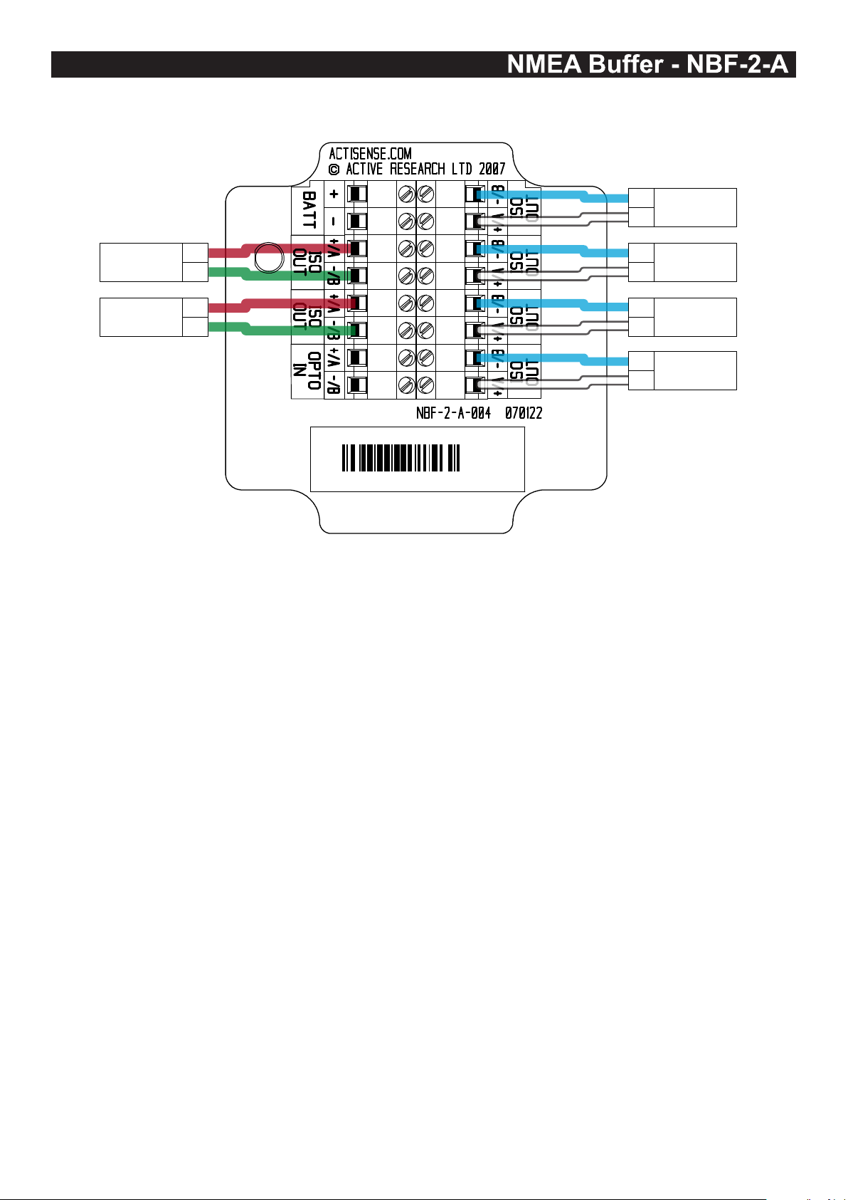
Figure 3 – Output connections
NMEA 0183 / RS422 Outputs
The NMEA 0183 / RS422 buffered outputs are capable of
driving more than 10 fully NMEA 0183 compliant listening
devices each. In practice, however, it is better to connect
just one NMEA listener per output to maintain the isolation
between each output. Figure 3 shows one possible
conguration of this preferred connection, using a
range of typical listeners that may be encountered.
NBF-2-A
In practice, this is rare, as most equipment is designed
to work well below this voltage level.
Personal Computer: The NBF-2 ISO-Drive outputs
are compatible with most personal computer RS232
port inputs. Connect PCs ‘Rx’ (Pin 2 on a standard 9Pin D-type) to NBFs ‘A/+’ and its ’G/Ground’ (Pin 5 on
D-type) to the NBFs ‘B/-’.
B
Listener 4
A
B
Listener 3
A
-
Listener 2
+
-
Listener 1
+
NMEA
NMEA
NMEA
NMEA
NMEA Listener devices 1, 2, 3 and 4: These devices
conform in full to the NMEA 0183 standard and their
connection ID’s match that of the NBF-2. Simply connect
like for like (“+” to “+”, “A” to “A” etc.). Examples of
both listener labelling types are shown.
NMEA Listener device 5: This device does not
conform in full to the NMEA 0183 standard and is a
“single-ended device”. Connection of single-ended
devices to a differential output used to be done with
caution, but the NBF-2 now makes this risk free.
Simply connect devices input, (which may be labelled
‘+‘ or ‘Rx’) to the NBF ‘+/A‘, and its ‘G/Ground’ to the
the NBF ‘-/B’.
The listener device should now be able to receive the
NMEA data correctly. This is not guaranteed, though,
as the instrument may have been designed to require
more than the 5v signal of the NBF-2 drive output.
Note: The PC will “see” a single-ended signal swinging
between plus and minus 5v. This is more than enough
for most PC receiver chips, which will normally operate
successfully down to +/-2v.
Note:
1. Wire colours are for guidance only.
Page 9© 2009 Active Research Limited
Page 10
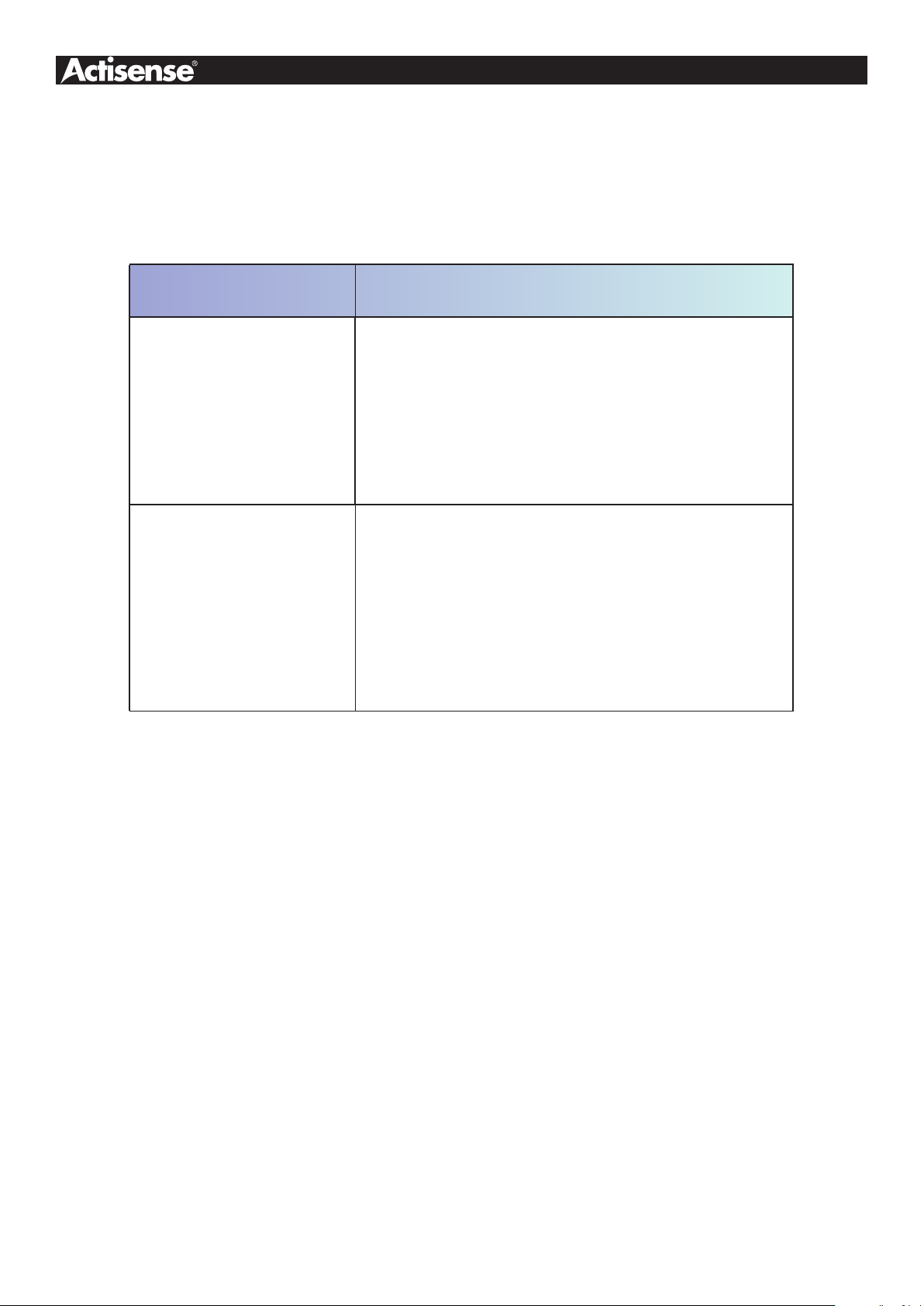
Troubleshooting guide
This guide will concentrate on all relevant troubleshooting issues above simple cable connection faults. Therefore, the
cables between the NBF-2 hardware and any other devices should be checked as a matter of course, before continuing
with this guide.
Problem / Error condition Required user response
Ensure that correct polarity of the NMEA connections have
been observed - NMEA connections are polarity sensitive.
No data seen on
NMEA instrument display
No data seen on
PC display
“+” and “A” connections should be wired to the NBF’s “+/A”.
“-” and “B” connections should be wired to the NBF’s “-/B”.
No damage should be caused if the polarity is reversed, but no
NMEA data will be seen on the receiving instrument.
Ensure that the PC software is selecting the correct PC Comms
port number and baud rate.
As a diagnostic, you can use the standard Windows
“HyperTerminal” utility to receive NMEA data. By setting the
input comms port to the one the NMEA NBF-2 is connected to,
the baud rate to that required (4800 normally), no parity, 1 stop
bit, 8 data bits and no ow control, the received NMEA text
data from the NBF-2 will be shown on the PC screen.
Table 1 – Troubleshooting guide
Page 10© 2009 Active Research Limited
Page 11
NMEA Buffer - NBF-2-A
Specications
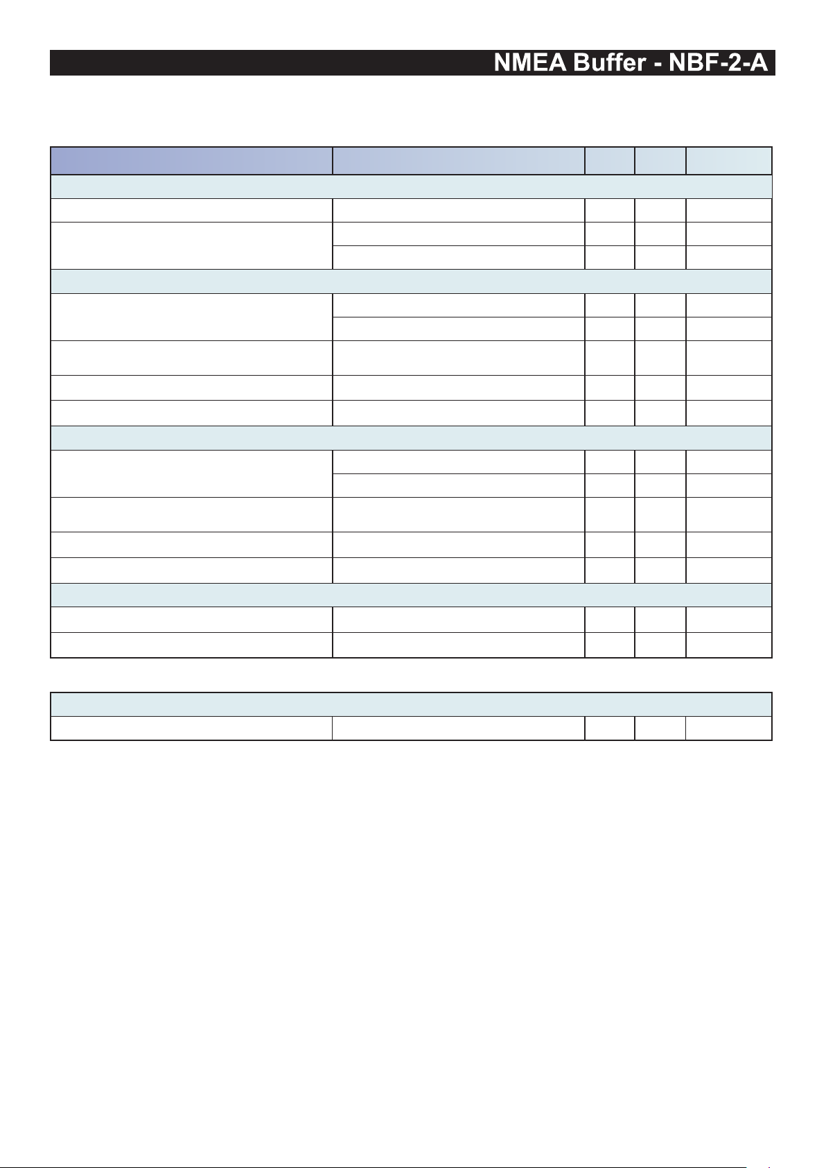
Parameter Conditions / Note Min. Max. Unit
Supply
Supply voltage (note 1) 8 45 V
Supply current no-load / full load (note 2,3)
OPTO Isolated Flexible Input
Supply voltage = 12v 43 100 mA
Supply voltage = 24v 25 50 mA
Input voltage between +/-
Input current
Differential input voltage Minimum level for data detection 1.8 2.0 V
Galvanic isolation Between input and ground 2500 V
ISO-Drive Flexible Output (RS-422, RS-485 and RS-232 compatible)
Output voltage between ISO Out +/A and
ISO Out -/B (under no load)
Output current (note 2,3)
Output short circuit current (note 4) 50 55 mA
Galvanic isolation Between output and ground 1500 V
Other parameters
Baud rate 115.2 Kbit/sec
Data propagation delay (typical) 1.7 2.1 us
General
Ambient temperature -20 +70 °C
Logical ‘1’ / stop bit -15.0 0.5 V
Logical ‘0’ / start bit 4.0 15.0 V
Maximum is under +35v overload
condition, min @2.0v input level
Logical ‘1’ / stop bit -4.8 -5.2 V
Logical ‘0’ / start bit 4.8 5.2 V
At maximum load, drive voltage
reduces to approx 2.7v
1.6 9.0 mA
- 27 mA
Table 2 – NBF-2 specications
All specications are taken with reference to an ambient temperature (TA) of +25°C.
Note:
1. Continuous supply voltage. The PSU used on the NBF-2 is a high specication switch-mode regulator, which
can operate for short periods at up to 80v, allowing the unit to easily pass the “SAE J1113” transient test, where a
transient impulse peaking at 80v is applied.
2. Current consumption measured under no-load and full-load conditions
3. “Full Load” is dened on a 100 ohm loads on each of the six ISO-Drive outputs, resulting in a net output current of
approximately to 162mA to all outputs.
4. Short circuit may be applied indenitely. The ISO-Drive output may be short-circuited directly to a 30 volt battery
supply without damage. A maximum current of 50mA will ow due to “polyfuse” auto-resetting fuse technology
being used in each output.
Page 11© 2009 Active Research Limited
Page 12

Order codes:
NBF-2 Standard NBF-2 (1 isolated input, 6 ISO-Drive outputs)
Company Information
Active Research Limited
5, Wessex Trade Centre
Ringwood Road
Poole
Dorset
UK
BH12 3PF
Telephone: 01202 746682 (International : +44 1202 746682)
Fax: 01202 746683 (International : +44 1202 746683)
Actisense on the Web: For advice, support and product details
“Actisense” is a registered trademark of Active Research Limited.
Page 12© 2009 Active Research Limited
 Loading...