

Page 1

actigraphcorp.com
User’s Manual
Document No. TAS14DOC07
Revision: A
Effective Date: 6/25/2014
49 E. Chase Street Pensacola, FL 32502 tel (850) 332-7900 fax (850) 332-7904
TAS14DOC07 User’s Manual Page 1 of 21
Page 2

About the
The following table describes the changes that have been made to this document
Revision
Description of Change/Documents Affected
Effective Date
A
- Initial Release
6/25/14
actigraphcorp.com
Change Page
change page
table
since its original conception. Documents affected by the changes made need to be
listed and updated in order to keep procedures up to date. This table shall be
maintained as long as this document is active.
49 E. Chase Street Pensacola, FL 32502 tel (850) 332-7900 fax (850) 332-7904
TAS14DOC07 User’s Manual Page 2 of 21
Page 3

actigraphcorp.com
Document Approval
Printed Name of Document Creator or Editor: ______________________________
Printed Name of Reviewing Manager: ______________________________ ☐ Approved
Signature: ________________________ Date: ________________________
Printed Name of Reviewing Quality Department Representative: ________________________________
Signature: ________________________ Effective Date: _________________________
*Hard copies are to be printed, signed, and kept on file with the Quality Department.
49 E. Chase Street Pensacola, FL 32502 tel (850) 332-7900 fax (850) 332-7904
TAS14DOC07 User’s Manual Page 3 of 21
Page 4

actigraphcorp.com
Table of Contents
Change Page .................................................................................................................................................. 2
Document Approval ...................................................................................................................................... 3
Table of Contents ...................................................................................................................................... 4
Important Information and Symbols ............................................................................................................ 6
Introduction ................................................................................................................................................ 10
Specifications and Functionality of the ActiGraph Link .............................................................................. 10
Data ......................................................................................................................................................... 10
Acceleration ........................................................................................................................................ 10
Gyroscope ........................................................................................................................................... 10
Magnetometer .................................................................................................................................... 11
Steps .................................................................................................................................................... 11
Inclinometer ........................................................................................................................................ 11
Low Frequency Extension ................................................................................................................... 12
Data Collection .................................................................................................................................... 12
Water Resistance ................................................................................................................................ 13
Wireless ................................................................................................................................................... 13
Heart Rate ........................................................................................................................................... 13
Wireless Reporting and Control .......................................................................................................... 13
Battery..................................................................................................................................................... 14
Low Voltage Mode (HALT) .................................................................................................................. 16
Recharging .......................................................................................................................................... 16
Wearing the Device ................................................................................................................................. 17
Miscellaneous Device Information ............................................................................................................. 17
Degradable Components ........................................................................................................................ 17
Other Possible Negative Effects .............................................................................................................. 17
Wear Locations ....................................................................................................................................... 17
Device Serial Number Label .................................................................................................................... 18
49 E. Chase Street Pensacola, FL 32502 tel (850) 332-7900 fax (850) 332-7904
TAS14DOC07 User’s Manual Page 4 of 21
Page 5

actigraphcorp.com
Cleaning the Device ................................................................................................................................ 18
Device Storage and Life Expectancy ....................................................................................................... 18
Device Maintenance ............................................................................................................................... 18
Accessories .............................................................................................................................................. 18
Connection and disconnect of detachable accessories ...................................................................... 19
Appendix ..................................................................................................................................................... 21
Risk Management Documentation ......................................................................................................... 21
49 E. Chase Street Pensacola, FL 32502 tel (850) 332-7900 fax (850) 332-7904
TAS14DOC07 User’s Manual Page 5 of 21
Page 6

The devices are compliant with IEC (International Electrotechnical Commission) standards
CAUTION: Do not simultaneously wear and charge, service, or provide any maintenance
the device.
actigraphcorp.com
Important Information and Symbols
The ActiGraph Link abides by the following regulations listed below and gives explanation into the
symbols that are found on each device.
CAUTION: The battery is to only be changed by trained ActiGraph personnel. The battery
is only allowed to be connected in a certain manner and any incorrect replacement can
result in a hazard.
for "Type BF Applied Part" - meaning they comply with requirements for user protection
against electrical shock. The housing of the device is the only part that is to come into
contact with the end user and is made out of Polycarbonate and/or Polyvinyl Chloride
materials. If you have any allergic reactions to Polycarbonate and/or Polyvinyl Chloride
materials, please consult your doctor before using an ActiGraph device.
on the device. The end user should not be in the patient vicinity when being charged1
CAUTION: Transporting or operating these devices outside of the temperature range of
o
-10
C to +55oC could lead to dangerous conditions and/or incorrect data collection.
CAUTION: Modification to ActiGraph devices is not permitted and will void all warranties
if tampered and/or modified. Do not modify the device in any way.
CAUTION: Do not swallow any part of this device. If a piece has been swallowed, contact
your local poison control hotline or seek medical attention as soon as possible.
NOTICE: Device does not have any contraindication(s)
NOTICE: Only use a USB 2.0 cable to connect to the charger. Only use ActiGraph’s
approved USB hubs to charge the device. Do not connect the device to anything else but
a computer and an ActiGraph approved USB hub.
NOTICE: No precautions need to be taken in the event of changes in the performance of
Class II medical device
1
A patient vicinity is areas in which PATIENTS are normally cared for and the space with surfaces likely to be contacted by the
PATIENT or an attendant who can touch the PATIENT. This encloses a space within the room 1,83 m (6 feet) beyond the perimeter
of the bed (examination table, dental chair, treatment booth, and the like) in its intended location, and extending vertically 2, 29 m (71/2 feet) above the floor.
49 E. Chase Street Pensacola, FL 32502 tel (850) 332-7900 fax (850) 332-7904
TAS14DOC07 User’s Manual Page 6 of 21
Page 7

These devices comply with part 15 of the FCC Rules. Operation is subject to the
Connect the equipment into an outlet on a circuit different from that to which the
Consult the dealer or an experienced radio/TV technician for help.
The devices are classified as Class I medical devices within the European Union and have
actigraphcorp.com
following two conditions: (1) This device may not cause harmful interference, and (2)
this device must accept any interference received, including interference that may
cause undesired operation. Changes or modifications not expressly approved by
ActiGraph, LLC will void the user's authority to operate the equipment under FCC
regulations.
• FCC Part 15.107 – AC Conducted Emissions
• FCC Part 15.109 – Radiated Emissions
• FCC Part 15.207 – Modular Transmitter AC Line Conducted Emissions
• FCC Part 15.249 – Radiated Emission Limits of Intentional Radiators
Note: This equipment has been tested and found to comply with the limits for a Class B
digital device, pursuant to part 15 of the FCC Rules. These limits are designed to provide
reasonable protection against harmful interference in a residential installation. This
equipment generates, uses and can radiate radio frequency energy and, if not installed
and used in accordance with the instructions, may cause harmful interference to radio
communications. However, there is no guarantee that interference will not occur in a
particular installation. If this equipment does cause harmful interference to radio or
television reception, which can be determined by turning the equipment off and on, the
user is encouraged to try to correct the interference by one of more of the following
measures:
• Reorient or relocate the receiving antenna.
• Increase the separation between the equipment and receiver.
•
receiver is connected.
•
been approved to be sold as medical devices according to the European Union's
regulatory requirements listed below:
rd
• EN 60601-1 (3
Edition) – Medical Electrical Equipment Part 1: General
Requirements for Safety
• EN 60601-1-2:2007, inc. C:2010 – Medical Electrical Equipment Part 1-2: General
Requirements for Basic Safety and Essential Performance – Collateral Standard:
Electromagnetic Compatibility – Requirements and tests IEC 60601-1-2 (Modified)
• EN 61000-4-2:2009 – Electromagnetic Compatibility – Part 4: Testing and
measurement techniques – Section 2: Electrostatic discharge immunity test
• EN 61000-4-3:2006, inc. A2:2010 – Electromagnetic Compatibility – Part 4: Testing
and measurement techniques – Section 3: Radiated, radio-frequency,
electromagnetic field immunity test
• EN 61000-4-8:2010 – Electromagnetic Compatibility – Part 4: Testing and
measurement techniques – Section 8: Power frequency magnetic field immunity
test
49 E. Chase Street Pensacola, FL 32502 tel (850) 332-7900 fax (850) 332-7904
TAS14DOC07 User’s Manual Page 7 of 21
Page 8

• EN 55011:2009, inc. A1:2010 – Limits and methods of measurement of radio
Zealand
exempt RSS standard(s). Operation is
subject to the following two conditions: (1) this device may not cause interference, and
(2) this device must accept any interference, including interference that may cause
radio exempts de licence. L'exploitation est autorisée aux deux conditions suivantes : (1)
tout brouillage radioélectrique subi, même si le brouillage est susceptible d'en
Physiological
Effects
actigraphcorp.com
disturbance, characteristics of industrial, scientific and medical radio frequency
equipment
• EN 301 489-1 – Electromagnetic compatibility and Radio spectrum Matters (ERM);
ElectroMagnetic Compatibility (EMC) standard for radio equipment and services;
Part 1: Common technical requirements
• EN 301 489-3 V1.4.1 – Electromagnetic compatibility and Radio spectrum Matters
(ERM); Electromagnetic Compatibility (EMC) standard for radio equipment; Part
3: Specific conditions for Short-Range Devices (SRD) operating on frequencies
between 9kHz and 40GHz
• EN 300 328 – Electromagnetic compatibility and Radio spectrum Matters (ERM);
Wideband transmission systems; Data transmission equipment operating in the
2.4 GHz ISM band and using wide band modulation techniques
The devices comply with Industry Canada license-
undesired operation of the device.
Le présent appareil est conforme aux CNR d'Industrie Canada applicables aux appareils
l'appareil ne doit pas produire de brouillage, et (2) l'utilisateur de l'appareil doit accepter
Australia/New
compromettre le fonctionnement.
The devices comply with the Australian and New Zealand standards:
• AS/NZS 4268 (2008) – Radio equipment and systems – Short range devices
• AS/NZS CISPR 11:2011 - Information technology equipment – Radio disturbance
characteristics – Limits and methods of measurement
• AS/NZ CISPR 22 (2009) – Information technology equipment – Radio disturbance
characteristics – Limits and methods of measurement
This device does not produce any known physiological effects.
This device is manufactured Lead-Free and complies with RoHS standards (Restriction of
the Use of Certain Hazardous Substances in Electrical and Electronic Equipment)
49 E. Chase Street Pensacola, FL 32502 tel (850) 332-7900 fax (850) 332-7904
TAS14DOC07 User’s Manual Page 8 of 21
Page 9
The devices are water resistant in accordance with IEC 60529 and have the International
Protection Rating: IP27 or immersion in one (1) meter of water for up to 30 minutes.
Do not expose the devices to temperatures outside the limitations of -10oC to +55oC. If a
the device as close to the user as possible to try and insulate the device.
actigraphcorp.com
IP27
Contact ActiGraph Customer Service regarding the disposal of these products.
Environmental
Conditions
device is going to be exposed to temperatures higher than +60oC, keep the device isolated
from the user. If a device is going to be exposed to temperatures lower than -10
o
C, keep
49 E. Chase Street Pensacola, FL 32502 tel (850) 332-7900 fax (850) 332-7904
TAS14DOC07 User’s Manual Page 9 of 21
Page 10
Parameter
Primary
Secondary
Units
Axis
3
3
Sensitivity
0.5
4
mg/LSB
Dynamic Range
+/-16
+/- 8
g
Parameter
Value
Units
Axis 3
Sensitivity
0.06
Deg/LSB
actigraphcorp.com
Introduction
The ActiGraph Link activity monitors provide objective measurements of human activity and are used in
many research and clinical applications. They include a microelectromechanical system (MEMS) based
accelerometer, gyroscope, magnetometer, and a capacitive touch based wear sensor as data collection
end points. No formal training is required to use the ActiGraph Link and patients may be the intended
operator. This document will serve as the only necessary training guide needed to get full functionality
from the device.
Specifications and Functionality of the ActiGraph Link
Data
The Link includes two accelerometers, gyroscope, and magnetometer sensors. Data will not be
negatively affected by lint, dust, or direct sunlight.
Acceleration
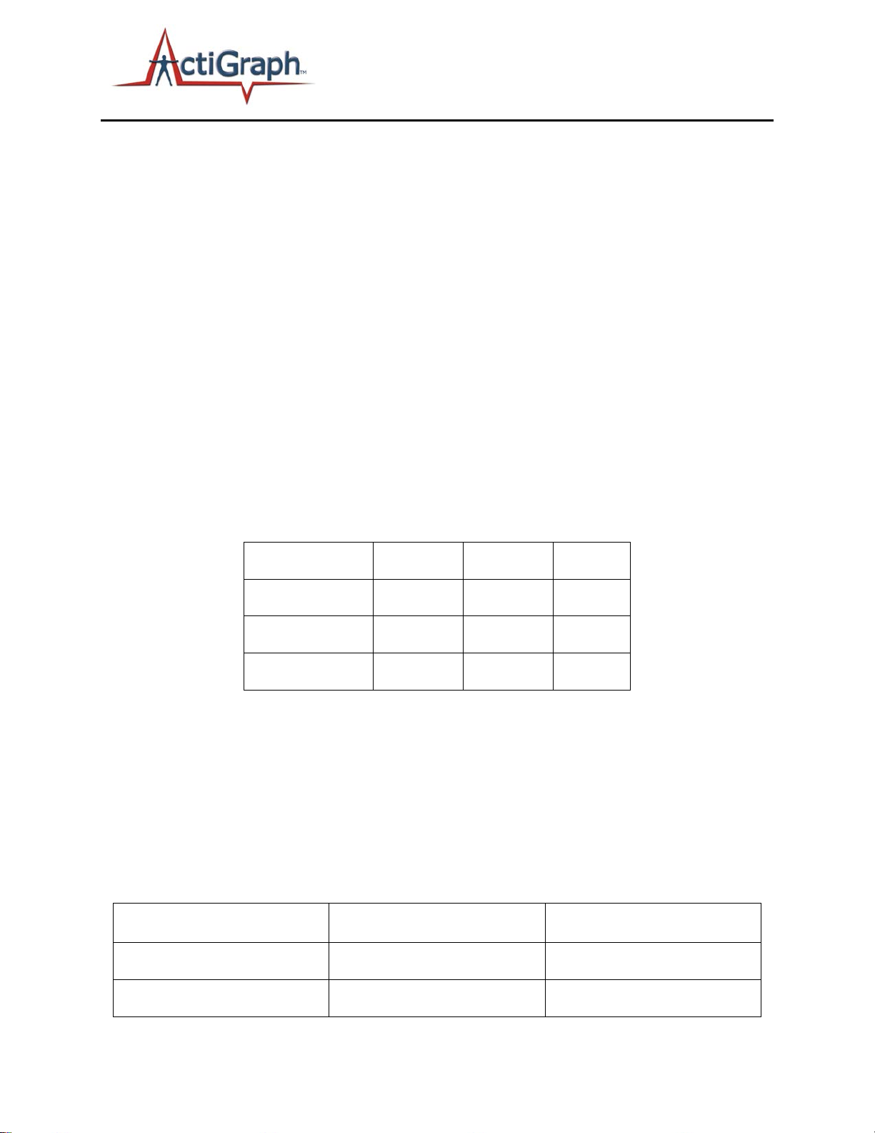
Acceleration is measured by two accelerometers; a primary that is utilized for all historical and standard
data collection efforts and a secondary which is used in very specific use cases where a higher dynamic
range is necessary.
Table 1 – Accelerometer Key Specifications
Acceleration data from the primary sensor is sampled at rates ranging from 30 Hz to 100 Hz (user
selectable) and the secondary accelerometer data is sampled at a fixed 100 Hz. Output from both
devices are stored in a raw, non-filtered/accumulated format in the units of gravity (g’s). This data is
stored directly into a non-volatile flash memory. The accelerometer is very sensitive and is accurate
within +/- 0.5% of the data collected.
Gyroscope
A three axis gyroscope collects angular velocity in units of degrees/sec. Data is sampled at 100 Hz.
49 E. Chase Street Pensacola, FL 32502 tel (850) 332-7900 fax (850) 332-7904
TAS14DOC07 User’s Manual Page 10 of 21
Page 11
Dynamic Range
+/- 2000
Deg/sec
Parameter
Value
Units
Axis 3
Sensitivity
0.6
µT/LSB
Dynamic Range
+/- 4800
υ
Inclinometer Code
0
Device Off (Not Being Worn)
1
Subject Standing
2
Subject Lying Horizontal
3
Subject Sitting
actigraphcorp.com
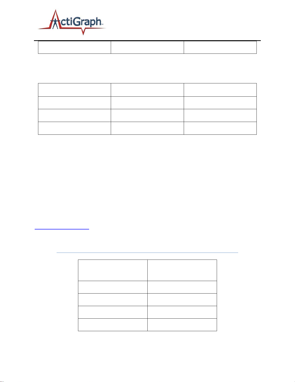
Table 2 – Gyroscope Key Specifications
Magnetometer
A three axis gyroscope collects angular velocity in units of degrees/sec. Data is sampled at 100 Hz.
T/LSB
Table 3 – Magnetometer Key Specifications
Steps
Step counts are accumulated on a per-epoch basis and are based on accelerometer data collected on
the vertical axis. An algorithm present in the device firmware filters out the accelerometer’s baseline
noise level to help accurately accumulate the steps-per-epoch.
Inclinometer
The inclinometer feature can help users identify the orientation of the device and, more importantly,
when the device itself was taken off. Each epoch is flagged with a number (1 through 4) to indicate the
orientation of the device during that epoch. For ActiGraph Link devices, this is done within the ActiLife
software when converting the *.gt3x file to *.agd format. As noted, the inclinometer feature is only
valid when the device is worn vertically on the point of the hip. More details are available in the
Inclinometer Whitepaper
Important The inclinometer feature is only valid if the device is worn on the hip
with Axis 1 upward facing.
.
Interpretation
(Stored with each Epoch)
49 E. Chase Street Pensacola, FL 32502 tel (850) 332-7900 fax (850) 332-7904
Table 4 - Inclinometer Definitions
TAS14DOC07 User’s Manual Page 11 of 21
Page 12

actigraphcorp.com
Off Indication on ActiGraph Link versus other devices
The Inclinometer feature offers researchers the ability to detect periods of time during which the device
was not worn. For devices other than the wGT3X+, wActiSleep+, GT3X+, and ActiSleep+, the
inclinometer algorithm makes this prediction by examining the angle at which the device is placed. In
the wGT3X+, wActiSleep+, GT3X+, and ActiSleep+ devices, off detection is performed by analyzing both
the angle at which the unit is placed as well as the length of time the device remains still. Absolute
stillness for three (3) minutes indicates that the unit is likely in an “off” condition regardless of
orientation. As such, epochs that follow three motionless minutes of activity are flagged as “off,” i.e.,
the inclinometer code is equal to zero. These values are not retroactive. That is, the first three minutes
of zero activity are not flagged as “off.” In addition, 30 minutes in the “off” orientation will cause the
inclinometer value to indicate off after that time period has elapsed regardless of motion.
At this time, the inclinometer feature is being validated by the research community.
Low Frequency Extension
The Low Frequency Extension (LFE) option, though not a mode or channel, is another data collection
option during post-processing for the ActiGraph Link. The Normal proprietary filter algorithm used in
ActiGraph products is used to eliminate any acceleration noise outside of the normal human activity
frequency bandwidth. This filter is customized to work with ActiGraph’s Energy Expenditure Algorithms
The LFE option, when enabled, extends the lower end (baseband) of the filter cutoff, effectively
expanding the bandwidth of the accumulated data. This option is useful when measuring actigraphy
data for subjects who move slowly or take very light steps (for example, the elderly). For more details,
contact ActiGraph at
.
Data Collection
During initialization, the user chooses the raw data sample frequency (30Hz up to 100Hz in 10Hz
increments). The ActiGraph Link collects data from all on-board sensors in raw data format. Data
recorded includes:
• Vertical Axis Activity Acceleration Data (Axis 1)
• Horizontal Axis Activity Acceleration Data (Axis 2)
• Perpendicular Axis Activity Acceleration Data (Axis 3)
• Ambient Light (Lux)
Although Steps and Inclinometer are not directly measured during data collection,
these values can be derived from the 3-axis data during *.gt3x file
decompression.
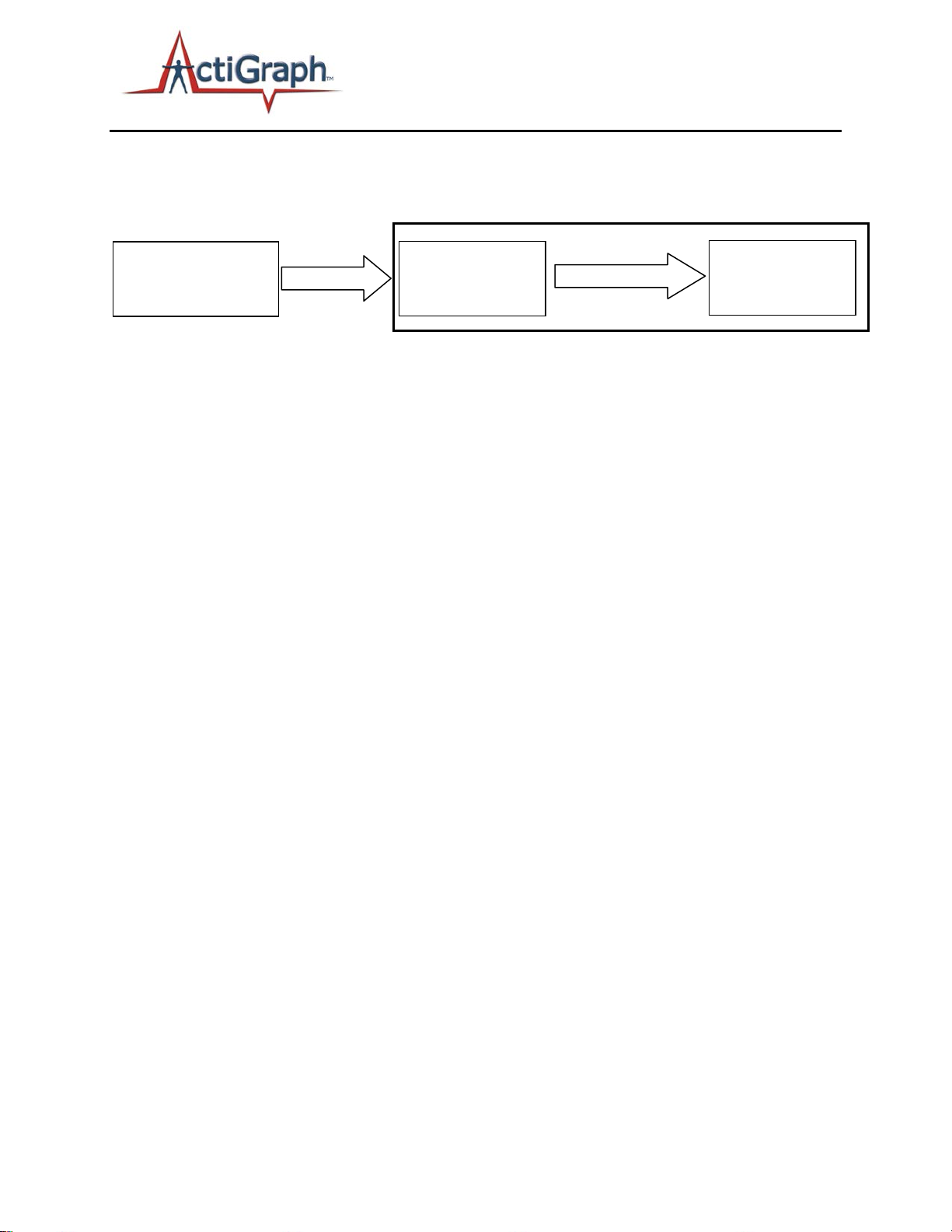
Unlike previous ActiGraph products, the ActiGraph Link does not filter or accumulate data into epochs.
Raw data is collected at the selected sample rate and is post-processed in the ActiLife. Because these
devices collect data from all sensors at all times, users can generate native ActiLife *.agd files containing
any desired combination of parametric data at a later time. This helps facilitate backward compatibility
49 E. Chase Street Pensacola, FL 32502 tel (850) 332-7900 fax (850) 332-7904
TAS14DOC07 User’s Manual Page 12 of 21
Page 13
Download
DeviceG
Raw Samples
(compressed/raw)
ActiLife
Filtering &
(.agd)
Compressed Raw
(*.gt3x)
Post-Processing
actigraphcorp.com
and enhances the flexibility of the data by allowing users to compare data to studies which use different
filter techniques or accumulation sizes (e.g., 1 second epochs versus 60 second epochs).
(30Hz-100Hz)
Zip File
Figure 1 – Raw Data Collection and Processing
Accumulation
Water Resistance
ActiGraph Link devices are water resistant in accordance with IEC 60529 IP27, or immersion in one (1)
meter of water for up to 30 minutes
Wireless
In addition to the standard features and functionality of their predecessor devices (wGT3X+ and
wActiSleep+), ActiGraph Link provides a wireless interface by way of Bluetooth 4.0
communication protocol. This 2.4 GHz based interface allows for interoperability with millions of
already fielded nodes as well as provides a means of rapidly gathering device and/or subject
information. The wireless functionality can be disabled when not needed in order to increase battery
life.
Heart Rate
By way of Blue Tooth Smart chest straps, the ActiGraph Link is capable of measuring and storing both
standard heart rate in Beats Per Minute (BPM) format as well as providing R-to-R measurements thus
enabling the researcher to better understand heart the subject’s activity profile.
TM
wireless
Wireless Reporting and Control
In addition to enhancing and increasing the sources for data collection, the wireless functionality of the
ActiGraph Link enables the user to perform many functions that previously required USB connection or
weren’t possible before. Many functions can now be performed in the field rather than requiring the
researcher to be tethered to a computer in the lab.
Initialization
The ActiGraph Link can be fully initialized wirelessly. This can be performed with ActiGraph’s new
ActiLife Mobile available on the iPhone and Android platforms.
Device Status
Device specific status information can be obtained. Some of the items retrieved include; firmware
version, battery voltage, current mode, subject name, and device serial number.
49 E. Chase Street Pensacola, FL 32502 tel (850) 332-7900 fax (850) 332-7904
TAS14DOC07 User’s Manual Page 13 of 21
Page 14

actigraphcorp.com
Stopping the device
In order to stop the device from collecting data, the device needs to be plugged into a computer with
the ActiLife Software running. One easy way to stop the device from collecting data is to set a stop time
during initialization. Once a device is told to stop, it will go into HALT mode and go into a low power
stopped state. Another way to get a device to stop collecting data is to plug it into a computer with the
ActiLife Software running and update the firmware on the device. This also will put it into HALT mode
and have the device go into a lower power stopped state.
Unexpected operations and events
If a device performs in an unexpected manner and does not collect data, does not perform as long as
expected, will not download data, or acts in any other manner that is unexpected, notify ActiGraph
immediately. ActiGraph’s Customer Service can be contacted at the phone number (877) 497-6996 and
is available every week, Monday through Friday, 8A.M. to 5P.M Central Standard Time. Customer
Service may also be contacted through email at [email protected]
Household Interference
Within a household environment many different factors can negatively affect the device. Putting a
device close to hot sources, such as a fireplace and baseboard heater, will melt the housing of a device
and destroy it. Putting a device in the freezer for extended periods of time will reduce the capacity of
the battery’s lifespan and negatively affect its performance. Putting a device in a microwave will destroy
various parts of the device and possibly completely destroy it. Wireless internet connections, wireless
television service, and other wireless services will not negatively affect the performance of the device.
As a rule of thumb, do not put the device in extreme cold or hot temperatures and do not apply any
electrical sources to the device unless explicitly approved and described by ActiGraph.
.
Battery
All ActiGraph devices use a lithium polymer rechargeable battery that has a maximum voltage of
approximately 4.20 volts and have a total life expectancy of five (5) years. Even though these batteries
are replaceable, only ActiGraph personnel are to replace the batteries. At 3.1 volts the devices enter a
low voltage mode state (HALT mode).
In order to slow the aging of the lithium polymer battery, it is recommended that devices be stored in a
partially charged state (40 – 60% battery capacity) in low ambient temperatures. Every three (3) months
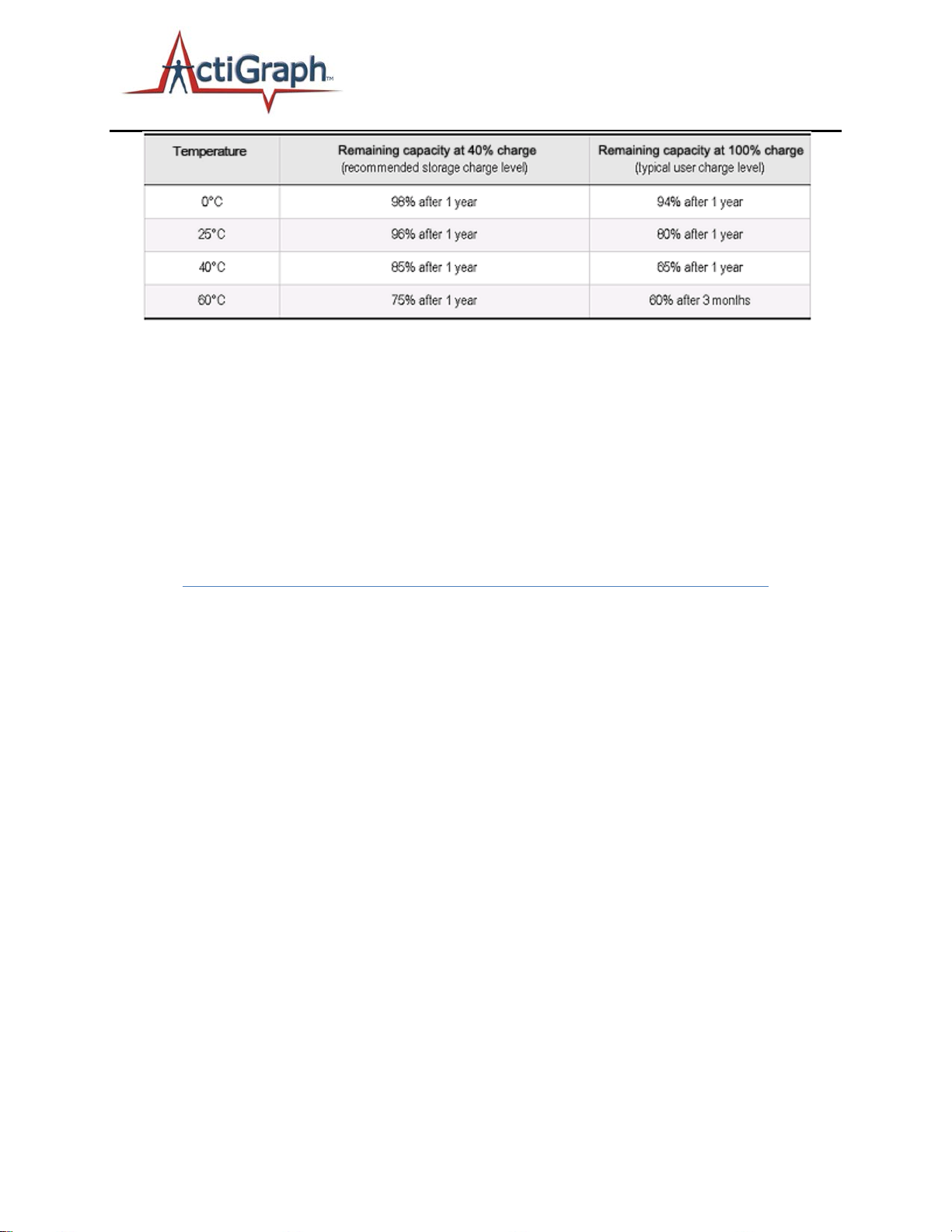
plug the devices in to monitor their voltages and to extend the life expectancy of the battery. Table 5
demonstrates the impact of storage temperature and charge state on battery long term capacity.
49 E. Chase Street Pensacola, FL 32502 tel (850) 332-7900 fax (850) 332-7904
TAS14DOC07 User’s Manual Page 14 of 21
Page 15
actigraphcorp.com
Note: If a computer is not available or if multiple devices need to be recharged, a
self-powered USB hub can be used.
IMPORTANT: ActiGraph’s devices do not come fully charged from the
manufacturer and recommend the units be charged fully before their initial use.
If the battery performance is not performing as expected, call ActiGraph’s
Customer Service immediately.
Table 5 - Lithium Polymer Storage
49 E. Chase Street Pensacola, FL 32502 tel (850) 332-7900 fax (850) 332-7904
TAS14DOC07 User’s Manual Page 15 of 21
Page 16
ActiGraph Link
Battery Life
(Days)
Memory Limit
(Days)
30
16
120
ActiGraph Link
Sample Rate (Hz)
Battery Life
(Days)
Memory Limit
(Days)
30
10
120
actigraphcorp.com
Sample Rate (Hz)
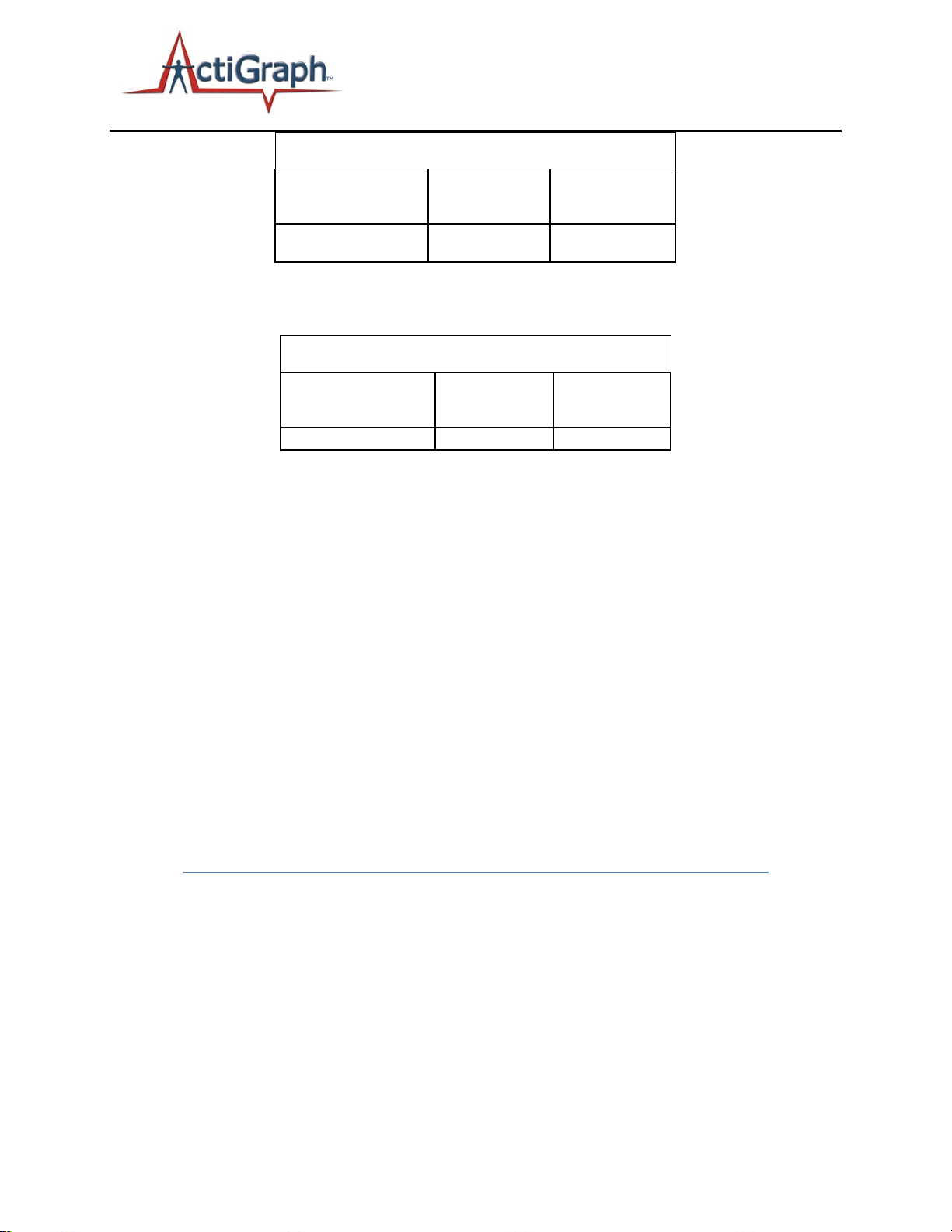
Table 6 – Battery life based on 16 Hrs Active, 8 Hrs sleep.
Table 7 – Battery life based on no sleep (24 hrs active).
Low Voltage Mode (HALT)
ActiGraph devices enter a “Low Voltage Mode” (or HALT) state when the battery discharges beyond a
point of being able to power the device. In this mode, all important variables and data are stored in
flash memory to secure the device download. Because the device’s internal clock stops in HALT mode,
the device cannot be recharged and redeployed; the device must be downloaded and reinitialized to
continue use.
Recharging
Recharging is automatic and is accomplished by connecting the device to ActiGraph’s charging station.
Charging time will depend on the battery life, but typically will not exceed three hours for a fully
depleted battery to become fully charged. If the battery voltage drops below 3.1 volts while in use, the
device will not have sufficient power to collect data and will display a warning to the user. The battery
level, reported in volts, can be viewed at any time by starting the ActiLife software and plugging in the
device.
Important: ActiLife will not allow initialization if the voltage is below 3.85 volts.
49 E. Chase Street Pensacola, FL 32502 tel (850) 332-7900 fax (850) 332-7904
TAS14DOC07 User’s Manual Page 16 of 21
Page 17

actigraphcorp.com
Wearing the Device
All ActiGraph activity monitors are designed to monitor activity and record energy expenditure (calories
spent during normal activity, METs, everyday activity, and exercise). Additionally, these devices can also
function as a very accurate sleep assessment tool
data, the device should be affixed securely to the body’s center-of-mass to ensure the most accurate
caloric measurements. Wrist worn (non-validated) EE for kids is now available for 3-axis ActiGraph
devices. When being used for sleep assessment, ActiGraph devices may be worn anywhere on the body:
wrist, waist (hip), arm, or ankle.
It is recommended that children under 12 years of age wear ActiGraph devices on the elastic belt (versus
the adhesive belt clip) as it is the most secure way to wear the device. Belt loop pouches, wrist and
ankle straps are also available.
If irritation of the skin occurs due to wearing the device, discontinue wearing the device and consult a
doctor for treatment. Although the Polycarbonate and Polyvinyl Chloride materials are not known to be
irritating to the skin, some irritation to individuals with sensitive skin may occur. If this happens, consult
your doctor for treatment and stop wearing the device. Also, notify the individual that issued the device
to you that you have taken the device off since data collection will be effected.
2
. While collecting day-to-day energy expenditure
Miscellaneous Device Information
Degradable Components
ActiGraph’s devices are made with high quality components that are not subject to deterioration over
time. The battery within each device is the only component that has a determined life expectancy (5
years). If a device seems to be under-performing, call ActiGraph’s Customer Service department
immediately so the problem may be resolved. Batteries are only to be changed by ActiGraph trained
personnel.
Other Possible Negative Effects
Pets have the potential to destroy a device. Keep devices away from pets and other animals that may
chew on, bite, urinate on, swallow, and destroy a device in any other method imaginable.
Wear Locations
ActiGraph’s devices can be worn in 6 different locations; the ankle, thigh, in a pants pocket, on the
waist, wrist, or on a lanyard around the neck. When initializing the ActiGraph Link within ActiLife,
choose the appropriate wear location to ensure accurate data collection.
2
Sleep analysis can also be performed by purchasing ActiGraph’s ActiSleep analysis program, which is part of the Virtual
Trainer, web-based, analysis software. Formulas for this tool were developed by Dr. Avi Sadeh. Department of Psychology,
Tel Aviv University.
49 E. Chase Street Pensacola, FL 32502 tel (850) 332-7900 fax (850) 332-7904
TAS14DOC07 User’s Manual Page 17 of 21
Page 18

actigraphcorp.com
Device Serial Number Label
Each ActiGraph device is equipped with a label stuck to it with pertinent device information inside the
serial number. For example the serial number MRA3A29120016 means:
• MRA3 = device model
• A = device model version
th
• 29 = week of the year it was manufactured (29
• 12 = year it was manufactured (2012)
• 0016 = number of device manufactured that week
week)
Cleaning the Device
ActiGraph devices are approved to be cleaned with a non-abrasive cloth and isopropyl alcohol. For
optimal results, apply isopropyl alcohol to the cloth, clean the device for 15-20 seconds, and let air dry.
ActiGraph devices are not to be sterilized because damage may occur. Though ActiGraph devices are
not required to be cleaned on any predetermined schedule, it is advised that the devices be cleaned
after each use by a user.
Device Storage and Life Expectancy
There is no specific requirement for storing ActiGraph devices but a dry location with temperature
limitations between 0°C and 50°C is suggested. For optimal battery life expectancy, routinely charge the
device according to Table 5.
The only limiting factor of an ActiGraph device when calculating life expectancy is the battery. The
battery has a life expectancy of five (5) years but can be replaced by ActiGraph personnel thus extending
the life of the device. The performance of the components inside the device does not degrade over
time so the life expectancy of a device is immeasurable.
Device Maintenance
ActiGraph’s devices do not require routine maintenance or calibration. Calibration is performed during
manufacturing of the device and will last for the life of the device. If maintenance is required on a
device, or a piece of a device has gone missing, call ActiGraph Customer Support or visit the support
section on the ActiGraph website www.actigraphcorp.com
Any critical components that require maintenance are to be performed by trained ActiGraph personnel
only. All necessary training manuals, schematics, parts listings, and other necessary documentation, will
be made available to the trained ActiGraph service technicians.
and initiate an RMA for your device.
Accessories
Accessories sold at ActiGraph are constantly changing due to the ever changing features available with
the ActiGraph Link. For a full list of current accessories available for the ActiGraph Link, please visit
ActiGraph’s website www.actigraphcorp.com/product-category/accessories
49 E. Chase Street Pensacola, FL 32502 tel (850) 332-7900 fax (850) 332-7904
TAS14DOC07 User’s Manual Page 18 of 21
. Use the accessories
Page 19
actigraphcorp.com
provided by ActiGraph only as described since the misuse of accessories and other detachable parts may
be harmful to the user.
The life expectancy of each accessory is different since each accessory is subject to different elements.
The USB caps have a life expectancy of 1-3 years. The Waist straps have a life expectancy of 5+ years.
The Wrist straps have a life expectancy of 5+ years. These are not exact life expectancies but are
suggested values that can be less or more depending on the use of the accessory.
Connection and disconnect of detachable accessories
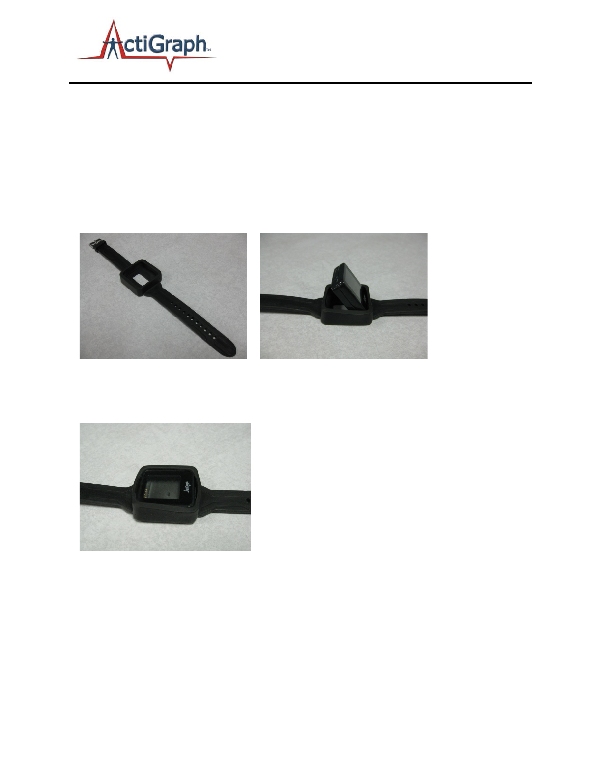
Wrist Watch
1) 2)
Step 1) Wrist watch by itself
Step 2) Insert device into one side of the watch device holder
3)
Step 3) Push the top of the device into the watch device holder until it is flush will the edges of the
watch
49 E. Chase Street Pensacola, FL 32502 tel (850) 332-7900 fax (850) 332-7904
TAS14DOC07 User’s Manual Page 19 of 21
Page 20
actigraphcorp.com
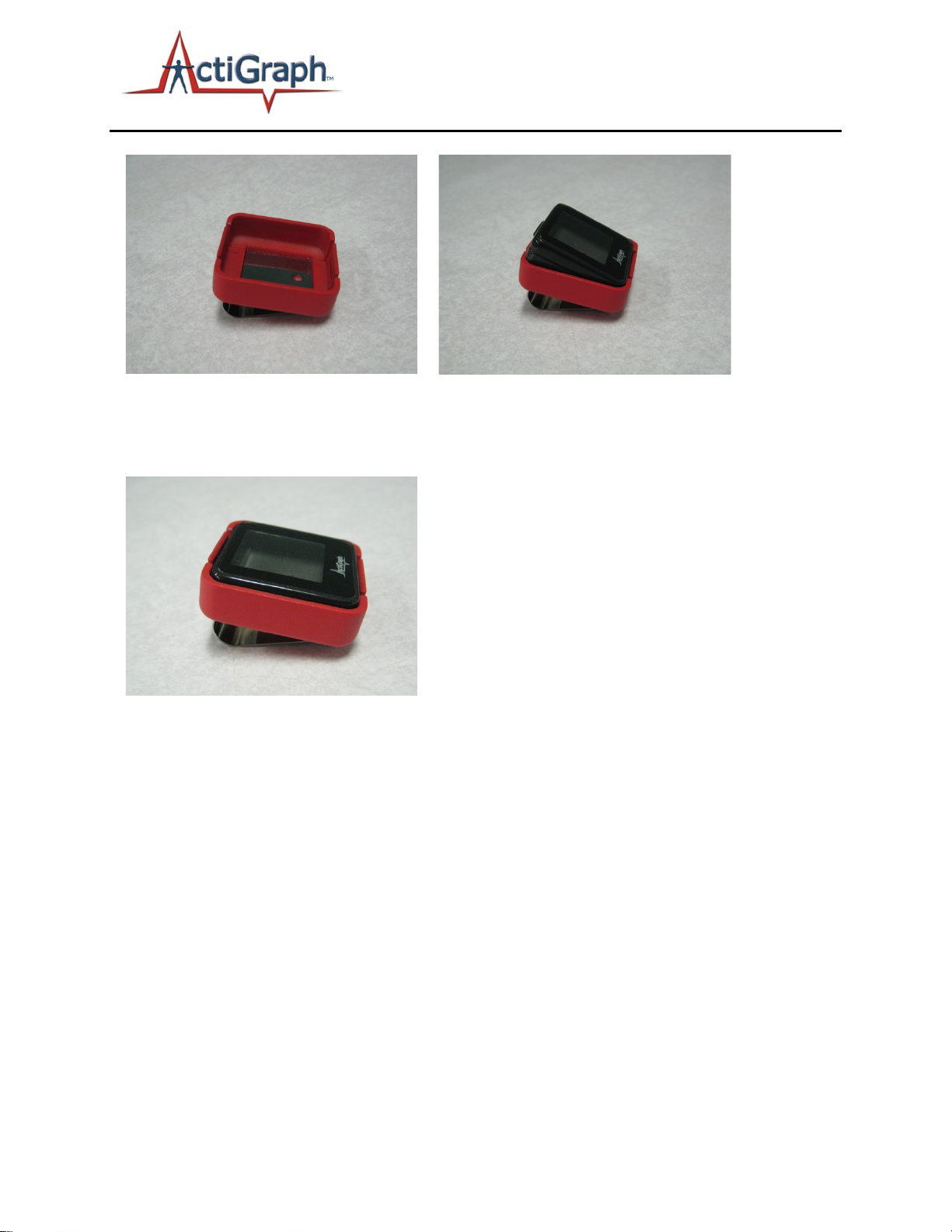
Belt Clip
1) 2)
Step 1) Belt clip by itself
Step 2) Insert the device into one side of the belt clip
3)
Step 3) Push the top of the device into the belt clip until you hear an audible “click” securing the device
into the belt clip
49 E. Chase Street Pensacola, FL 32502 tel (850) 332-7900 fax (850) 332-7904
TAS14DOC07 User’s Manual Page 20 of 21
Page 21
Document Number
Description
Revision
Effective Date
TAS14DOC02
Design Requirements
A
4/25/14
TAS14DOC01
Risk Management Plan
A
4/25/14
TAS14DOC04
Development Life-Cycle
A
4/25/14
TAS14DOC03
Risk Management Summary
A
4/25/14
TAS14TRD01
Taso Verification Plan
A
4/25/14
actigraphcorp.com
Appendix
Risk Management Documentation
Below is a required list of internal ActiGraph documents created or used to comprise the Risk
Management File for the ActiGraph Link.
49 E. Chase Street Pensacola, FL 32502 tel (850) 332-7900 fax (850) 332-7904
TAS14DOC07 User’s Manual Page 21 of 21
 Loading...