

Page 1

2014/01/10
Indoor Hemispheric
Mounting on the Wall
(Face Forward)
Installation Guide
For Models:
KCM-3911, B55, B56
Page 2

www.acti.com
Installation Guide
Table of Contents
Introduction ........................................................................ 3
Installation Procedures of KCM-3911 ............................... 4
Step 1: Unpack the Camera ...................................................................... 4
Step 2: Prepare Other Device Connectors (Optional) ............................. 4
Step 3: Install the Base Plate .................................................................... 5
Step 4: Attach the Camera to the Base Plate .......................................... 6
Step 5: Connect the Cables ...................................................................... 7
Step 6: Connect to Network ...................................................................... 9
Step 7: Access the Camera Live View ...................................................... 9
Installation Procedures of B5x Fisheye Domes ............ 10
Step 1: Drill the Holes .............................................................................. 10
Step 2: Prepare the Camera ..................................................................... 11
Step 3: Prepare Other Device Connectors (Optional) ........................... 12
Step 4: Install the Camera ....................................................................... 12
Step 5: Connect the Cable(s) .................................................................. 13
Step 6: Complete the Installation ........................................................... 14
Step 7: Access the Camera Live View .................................................... 15
Appendices ....................................................................... 16
How to Connect a Power Adapter (Optional) ........................................ 16
How to Connect DI/DO Devices (Optional) ............................................ 18
KCM-3911 DI/DO Connector ................................................................. 18
B5x Fisheye Dome DI/DO Connector ................................................... 21
Safety Information ............................................................ 24
2
Page 3
www.acti.com
Installation Guide
Camera Model
Description
Required Accessories
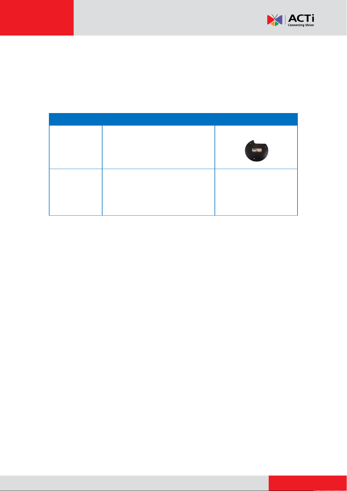
KCM-3911
The KCM-3911 comes with a bundled
mounting plate for installing the camera
on the surface. See Installation
Procedures of KCM-3911 on page 4.
Bundled Mounting Plate
B55, B56
This fisheye camera can be directly
installed on the surface without additional
mounting accessories. See Installation
Procedures of B5x Fisheye Domes on
page 10.
None
Introduction
This guide covers the step-by-step procedures in directly mounting the camera on a wall.
Bundled surface mounting accessories and connectors vary depending on model. Refer to the
installation procedures of your camera model as below:
3
Page 4
www.acti.com
Installation Guide
Installation Procedures of KCM-3911
Step 1: Unpack the Camera
1. Slightly twist the cover ring counter-clockwise and pull to detach it.
2. Remove the sticker label.
3. Set the camera aside for later installation.
Step 2: Prepare Other Device Connectors (Optional)
The camera supports external power supply with a DC12V power adapter and digital input /
output devices useful for event triggers, and audio input / output devices. The use of these
devices is optional depending on the user application. If a power adapter or DI/DO device will be
used, connect these devices to the corresponding terminal blocks supplied with the camera at
this point. Otherwise, skip this step.
Refer to the following sections for detailed information:
How to Connect a Power Adapter (Optional) on page 16
How to Connect DI/DO Devices (Optional) on page 18
4
Page 5
www.acti.com
Installation Guide
Screw hole
Camera Connectors Side
Base Plate
Connectors Side
Step 3: Install the Base Plate
IMPORTANT!
Before drilling the holes on the surface, note the camera placement and where you should drill
the hole where the cables will pass through or how the cable will go along the surface.
For wall installations, the connectors side must face up to install the camera with a correct
orientation.
1. After considering the orientation direction, drill the three (3) holes on the surface using the
drill template or the base plate itself as the template. If the cables will pass through the
surface, drill also the cable hole at this point.
5
Page 6
www.acti.com
Installation Guide
2. Secure the base plate to the surface using the supplied screws.
Step 4: Attach the Camera to the Base Plate
1. Align the screw holes of the camera to the base plate.
2. Secure the camera to the base plate using the supplied screws.
6
Page 7
www.acti.com
Installation Guide
Ethernet Cable
DC 12V
Power
Audio
Connector
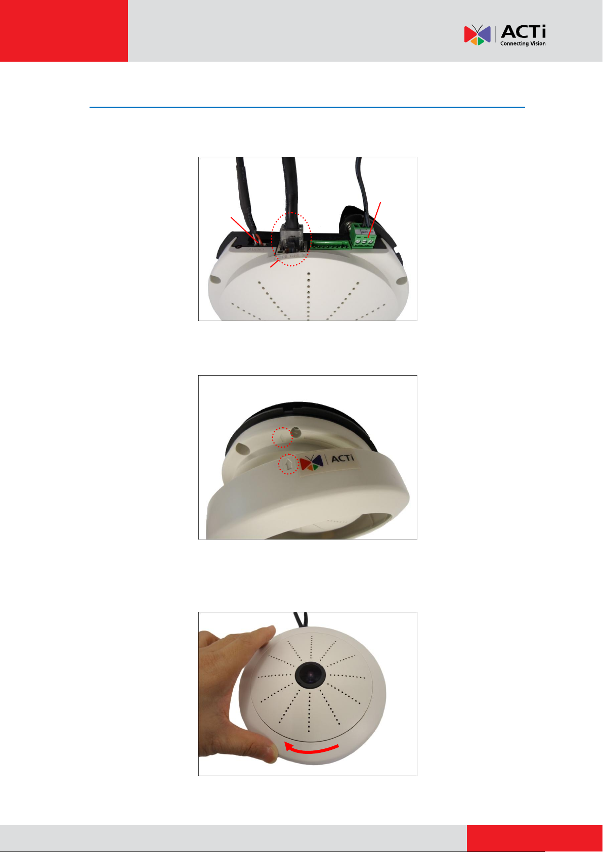
Step 5: Connect the Cables
1. Connect the bundled network cable and if necessary, other connectors, like audio, DC 12V
power, and DI/DO. Sample image below.
2. Attach the cover ring, take note that the arrow on the camera should be aligned with the
arrow on the cover ring.
NOTE: The cables must be slightly bent underneath the cover ring.
3. Twist the ring counter-clockwise to secure the ring to the camera.
7
Page 8
www.acti.com
Installation Guide
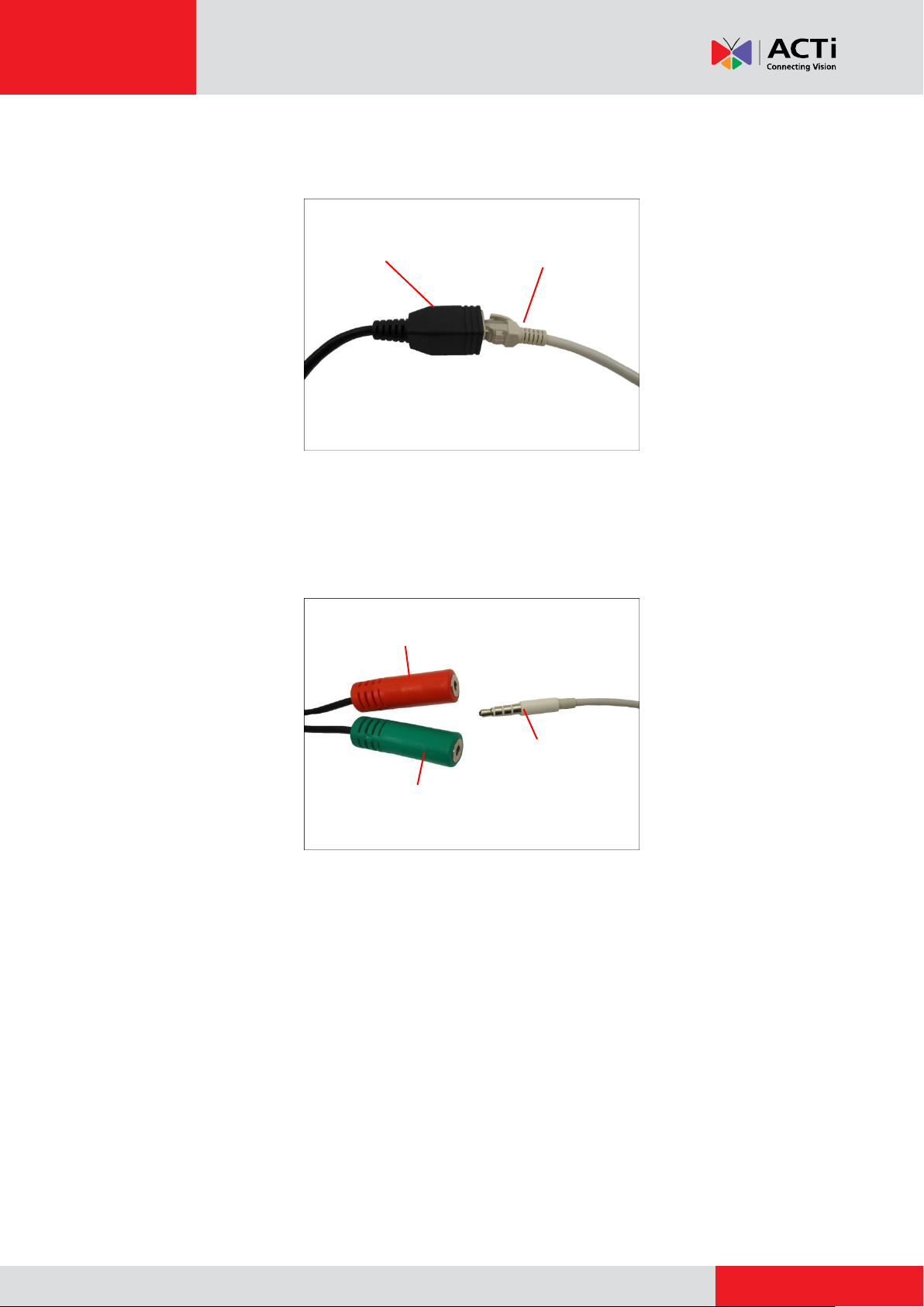
Network Side
Ethernet Port of
Camera Network Cable
Audio Input Jack
Audio Output Jack
Audio Device
4. Connect the Ethernet cable from the network side to the Ethernet port of the bundled network
cable.
5. If using an audio input device, such as a microphone with a built-in amplifier, connect the
device jack to the RED jack of the bundled audio cable. If using an audio output device, such
as a speaker, connect the device jack to the GREEN jack of the bundled audio cable.
Note: Make sure that the connected audio input device has a built-in amplifier. Connecting an
ordinary microphone will dwarf sounds and will result in inaudible recording.
8
Page 9

www.acti.com
Installation Guide
Network
AC Power
Source
PoE Injector /
Switch
Power Cable
Ethernet Cable
Ethernet Cable
(Data + Power)
Ethernet Cable
(Data)
Camera
Step 6: Connect to Network
On the network side, connect the other end of the Ethernet port to a switch or injector. Then,
connect the switch or injector to a network PC and a power source. See Power-over-Ethernet
(PoE) connection example below.
Step 7: Access the Camera Live View
Refer to the camera Hardware Manual downloadable from the website (www.acti.com) for more
information.
9
Page 10

www.acti.com
Installation Guide
Connectors Side
Installation Procedures of B5x Fisheye
Domes
Step 1: Drill the Holes
IMPORTANT!
Before drilling the holes on the surface, note the direction of the connectors side of the camera,
which is also the opposite side of the camera logo. This influences the camera placement and
where you should drill the hole where the cables will pass through or how the cables will go along
the surface. When installing the camera on the wall, the connectors side must either be facing
up or down.
1. Attach the drill template on the target surface, drill the holes and attach the plastic plugs (if
necessary).
2. If the cables will pass through the surface, drill also the cable hole at this point and pull the
cables through the hole on the surface.
3. Remove the drill template sticker from the surface.
10
Page 11

www.acti.com
Installation Guide
DO NOT Remove Film !
Step 2: Prepare the Camera
IMPORTANT: When the camera is taken out from the box, the lens is covered by a thin film. DO
NOT remove this film. It is used to protect the lens from scratches or fingerprint marks which may
happen during installation. Remove this film only after the camera is securely installed and all
connections are complete.
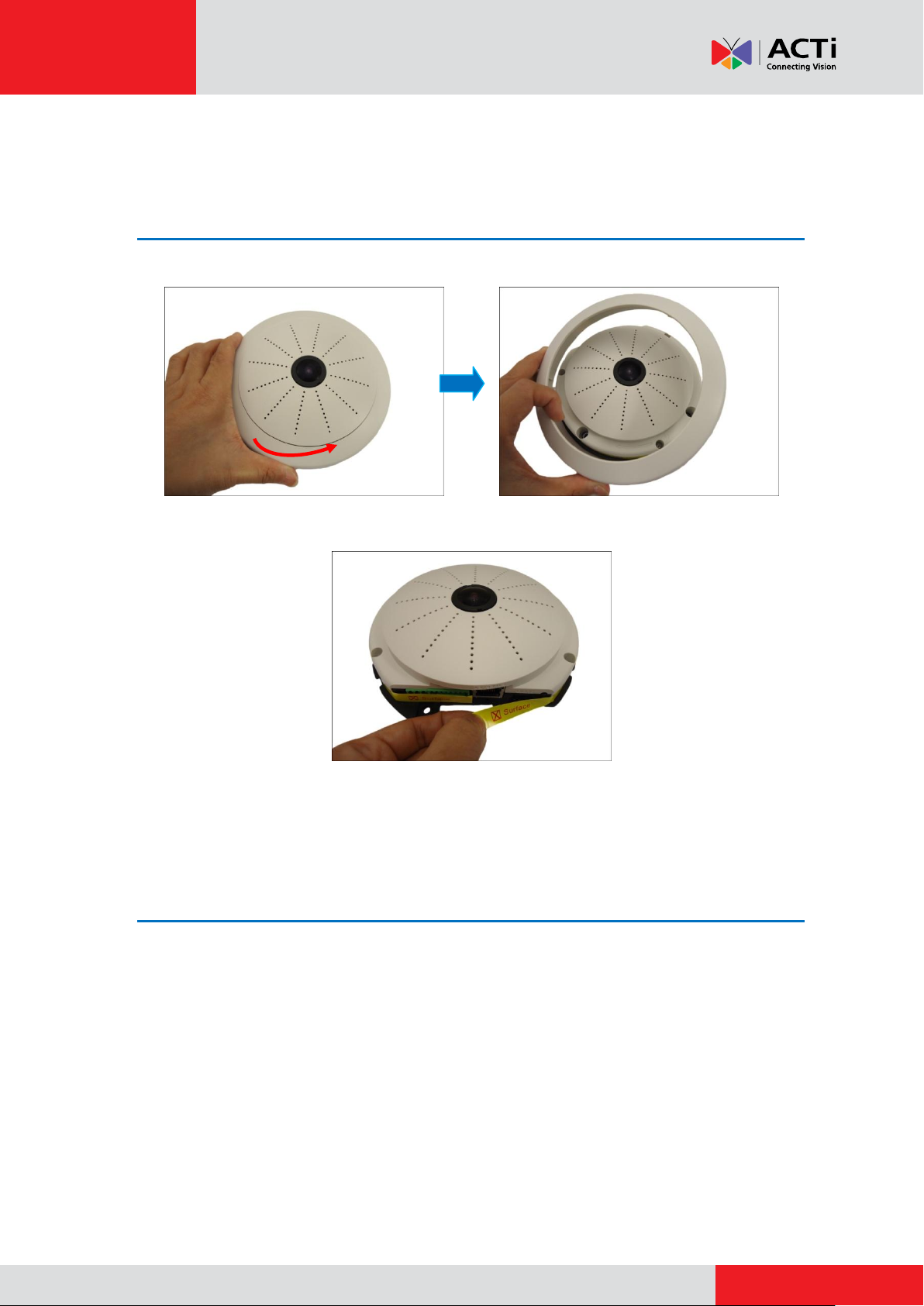
1. Slightly twist the cover ring counter-clockwise and pull to detach it.
2. If the cables will be routed along the surface, remove the cable tab from the cover ring. If
the cables will pass through the surface, skip this step.
3. Install a memory card into the memory card slot of the camera, as needed.
11
Page 12

www.acti.com
Installation Guide
Step 3: Prepare Other Device Connectors (Optional)
The camera supports external power supply with a DC12V power adapter and digital input /
output devices useful for event triggers, and audio input / output devices. The use of these
devices is optional depending on the user application. If a power adapter or DI/DO device will be
used, connect these devices to the corresponding terminal blocks supplied with the camera at
this point. Otherwise, skip this step.
Refer to the following sections for detailed information:
How to Connect a Power Adapter (Optional) on page 16
How to Connect DI/DO Devices (Optional) on page 18
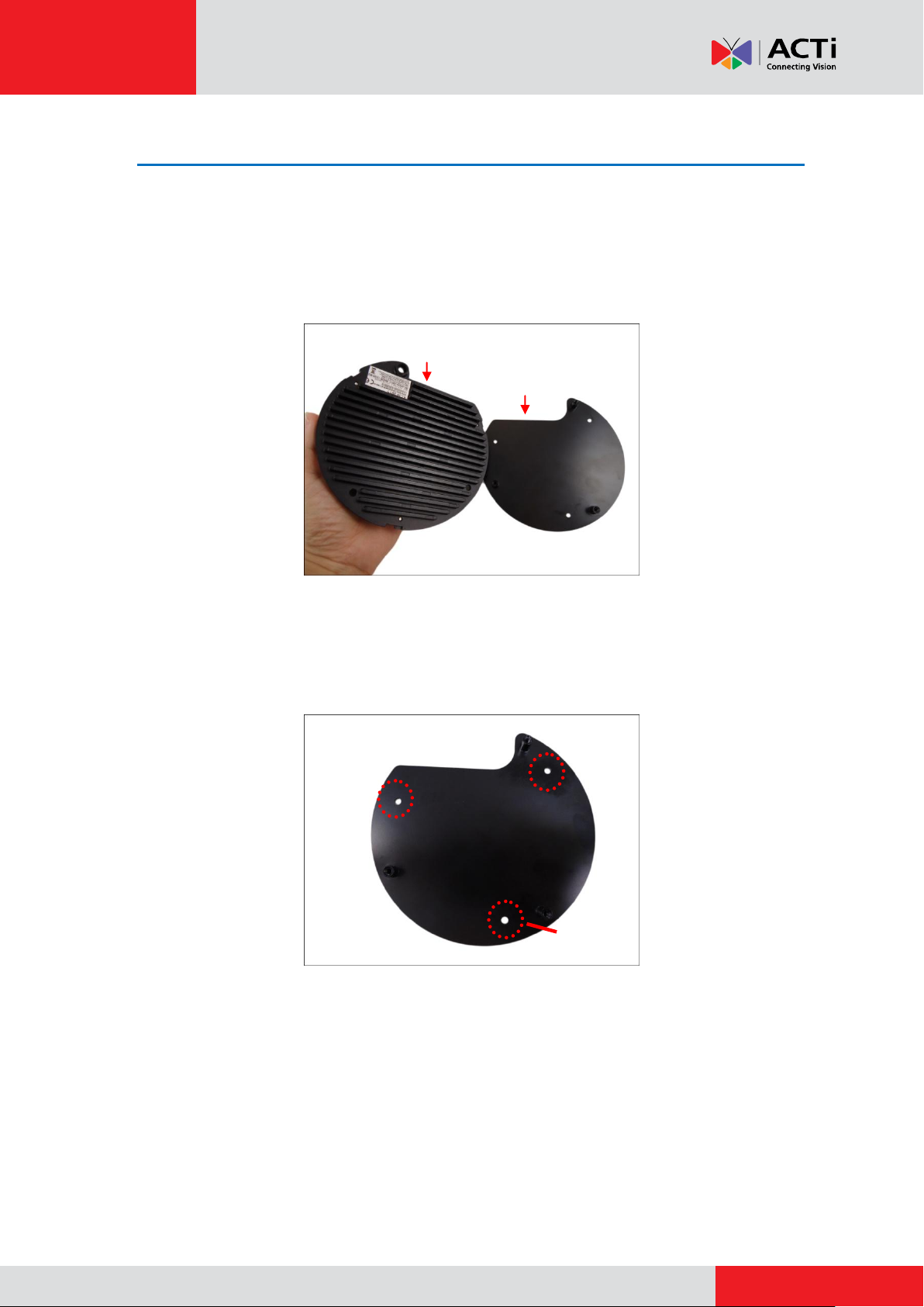
Step 4: Install the Camera
Install the camera using the three (3) supplied screws.
12
Page 13

www.acti.com
Installation Guide
Network
AC Power
Source
PoE Injector /
Switch
Power Cable
Ethernet Cable
Ethernet Cable
(Data + Power)
Ethernet Cable
(Data)
Camera
Audio Out
Ethernet
DI / DO
Connector
DC 12V
Power
Audio In
Step 5: Connect the Cable(s)
1. Connect the Ethernet cable to the Ethernet port of the camera.
If necessary, connect other cable connectors (optional), like audio input/output, DC 12V
power, and DI/DO.
NOTE: The cables are not included in the camera package.
2. On the network side, connect the other end of the Ethernet port to a switch or injector. Then,
connect the switch or injector to a network PC and a power source. See Power-over-Ethernet
(PoE) connection example below.
13
Page 14

www.acti.com
Installation Guide
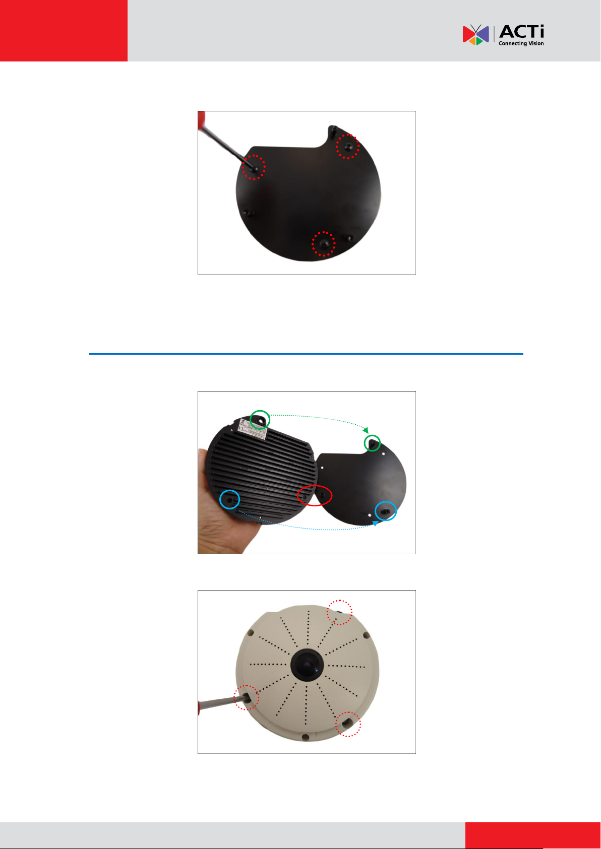
Step 6: Complete the Installation
1. Attach the cover ring, take note that the arrow on the camera should be aligned with the
arrow on the cover ring.
NOTE: If the cable(s) will be routed along the surface, route the cable(s) through the cable
gap of the cover ring.
2. Twist the ring counter-clockwise to secure the ring to the camera.
14
Page 15

www.acti.com
Installation Guide
3. Remove the thin film protecting the lens.
Step 7: Access the Camera Live View
Refer to the camera Hardware Manual downloadable from the website (www.acti.com) for more
information.
15
Page 16

www.acti.com
Installation Guide
White stripe: Connects to 12V Pin
Connects to GND Pin
Appendices
This section describes the procedures in preparing the external devices that you can connect to
the camera. The camera supports DC12V power input and Digital Input and Output (DI/DO)
devices using the bundled terminal blocks. The use of these devices, however, is optional.
How to Connect a Power Adapter (Optional)
In case of using a non-PoE switch or your PoE switch has limited power supply, you can
purchase a power adapter and directly connect the camera to a power outlet. The power adapter
must be connected to the supplied terminal block before use.
To do this, follow the procedures below:
1. Loosen the screws of the 12V and GND pins of the power terminal block.
2. Take note that a standard power adapter cable has two (2) different wires:
16
Page 17

www.acti.com
Installation Guide
3. Connect the wire with the white stripe to the 12V pin and the other to the GND pin.
4. Tighten the screws of the 12V pin and the GND pins to secure the wire connection.
5. Set the prepared power adapter for connection later. Below is an example of a power adapter
with an attached terminal block.
NOTE: The power adapter is not bundled in the package.
17
Page 18

www.acti.com
Installation Guide
Device
Pin
Mapping Instructions
Digital Input 1
(DI1)
1
GND
Connect the wires of the first input device to GND
(Pin 1) and DI1 (Pin 3).
3
DI1
Digital Input 2
(DI2)
5
GND
Connect the wires of the second input device to GND
(Pin 5) and DI2 (Pin 7).
7
DI2
7 8 6 5 4 3 2
1
How to Connect DI/DO Devices (Optional)
Depending on your surveillance needs, you may connect digital input or output devices to your
camera to trigger events or notifications.
Digital Input (DI) devices can be used to notify the camera about an activity in the camera site. DI
can be triggers of events. For example, you can connect a “panic button” to the camera; as such
when the panic button is pressed, the alarm signal will be sent through the camera. Other
common DI device applications are emergency button, smoke detector, passive infrared sensor,
etc.
Digital Output (DO) devices are external devices that are activated by the camera upon an event
inside the camera. For example, you can connect an “alarm horn” to the camera; as such when
an event occurs inside the camera (e.g. detected intruder), the alarm horn will sound. Other
common DO device applications are motion-triggered lights, electric fence, magnetic door locks,
etc.
KCM-3911 DI/DO Connector
You can connect up to two DI and two DO devices to your camera.
Press and hold the orange tab as you insert the wire through the pin slot, then release the orange
tab to secure the wire.
To connect input devices (DI), map the pins to one of the pin combinations below:
18
Page 19

www.acti.com
Installation Guide
Device
Pin
Mapping Instructions
Digital Output 1
(DO1)
2
12V
Connect the wires of the first output device to 12V
(Pin 2) and DO1 (Pin 4).
4
DO1
Digital Output 2
(DO2)
6
12V
Connect the wires of the second output device to 12V
(Pin 6) and DO2 (Pin 8).
8
DO2
Device
DI
Connection design
TTL - compatible logic levels
Voltage
To trigger (low)
Logic level 0: 0V ~ 0.4V
Normal (high)
Logic level 1: 3.1V ~ 30V
Current
10mA ~ 100mA
DO
Connection design
Transistor (Open Collector)
Voltage & Current
< 24V DC, < 50mA
To connect output devices (DO), map the pins to one of the pin combinations below:
The table below shows the DI/DO connection specifications:
Typical Connection
Based on these specifications, if the DI device has a voltage of 0V ~ 30V or the DO device has a
voltage of < 24V (<100mA), then the camera can supply internal power to these devices and
there is no need to connect the DI/DO device to an external power source.
In this case, wire connection to Pins 1 to 4. Use the GND and DI1 pins to connect a DI device and
use the 12V and DO1 pins to connect a DO device. See wiring scheme below:
Consequently, to connect a second DI or DO device, wire the connection to Pins 5 to 8.
19
Page 20

www.acti.com
Installation Guide
Relay
(DO1 Device)
Camera
Illuminator
110V-220V AC
External Power
Source
High Voltage DO Device Connection
Even though the camera provides 12V power, this may not be enough for some high voltage DO
devices, such as a ceiling light or a motor that opens or closes a gate. In this case, there is a
need to connect an external relay. See wiring scheme below:
Note that when choosing an appropriate relay, please refer to its specifications and make sure
they match the above design. The triggering circuit voltage has to be around 12V DC and the
switch-controlled circuit voltage has to match the external power supply (e.g. 110V AC or 220V
AC).
The illustration below is a graphic example of connecting a relay to a high voltage DO device.
NOTE: For more information on DI/DO connections, please refer to the Knowledge Base
article All about Digital Input and Digital Output downloadable from the link below
(http://www.acti.com/kb/detail.asp?KB_ID=KB20091230001).
20
Page 21

www.acti.com
Installation Guide
Device
Pin
Mapping Instructions
Digital Input
(DI)
1
DIO GND
Connect the wires of the first input device to DIO GND
(Pin 1) and DI (Pin 3).
3
DI
Digital Output
(DO)
2
DIO PW
Connect the wires of the first output device to DIO PW
(Pin 2) and DO (Pin 4).
4
DO
Device
DI
Connection design
TTL - compatible logic levels
Voltage
To trigger (low)
Logic level 0: 0V ~ 0.4V
Normal (high)
Logic level 1: 3.1V ~ 30V
Current
10mA ~ 100mA
DO
Connection design
Transistor (Open Collector)
Voltage & Current
< 24V DC, < 100mA
4 3 2
1
B5x Fisheye Dome DI/DO Connector
You can connect one DI and one DO device to your camera.
Press and hold the orange tab as you insert the wire through the pin slot, then release the orange
tab to secure the wire.
To connect an input (DI) or an output device (DO), map the wires to the pin combinations below:
The table below shows the DI/DO connection specifications:
21
Page 22

www.acti.com
Installation Guide
Typical Connection
Based on these specifications, if the DI device has a voltage of 0V ~ 30V or the DO device has a
voltage of < 24V (<100mA), then the camera can supply internal power to these devices and
there is no need to connect the DI/DO device to an external power source.
In this case, wire connection to Pins 1 to 4. Use the DIO GND and DI pins to connect a DI device
and use the DIO PW and DO pins to connect a DO device. See wiring scheme below:
High Voltage DO Device Connection
Even though the camera provides 12V power, this may not be enough for some high voltage DO
devices, such as a ceiling light or a motor that opens or closes a gate. In this case, there is a
need to connect an external relay. See wiring scheme below:
22
Page 23

www.acti.com
Installation Guide
Relay
(DO1 Device)
Camera
Illuminator
110V-220V AC
External Power
Source
Note that when choosing an appropriate relay, please refer to its specifications and make sure
they match the above design. The triggering circuit voltage has to be around 12V DC and the
switch-controlled circuit voltage has to match the external power supply (e.g. 110V AC or 220V
AC).
The illustration below is a graphic example of connecting a relay to a high voltage DO device.
NOTE: For more information on DI/DO connections, please refer to the article All about Digital
Input and Digital Output (http://www.acti.com/kb/detail.asp?KB_ID=KB20091230001) in the
Knowledge Base section of our website (www.acti.com).
23
Page 24

www.acti.com
Installation Guide
Safety Information
Read these instructions
You should read all the safety and operating instructions before using this product.
Heed all warnings
You must adhere to all the warnings on the product and in the instruction manual. Failure to follow
the safety instruction given may directly endanger people, cause damage to the system or to
other equipment.
Trademarks
All names used in this manual are probably registered trademarks of respective companies.
Liability
Every reasonable care has been taken during the writing of this manual. Please inform your local
office if you find any inaccuracies or omissions. We cannot be held responsible for any
typographical or technical errors and reserve the right to make changes to the product and
manuals without prior notice.
Cleaning
Disconnect this video product from the power supply before cleaning.
Attachments
Do not use attachments not recommended by the video product manufacturer as they may cause
hazards.
Do not use accessories not recommended by the manufacturer
Only install this device in a dry place protected from weather
Servicing
Do not attempt to service this video product yourself. Refer all servicing to qualified service
personnel.
24
Page 25

www.acti.com
Installation Guide
Damage Requiring service
Disconnect this video product from the power supply immediately and refer servicing to qualified
service personnel under the following conditions.
1) When the power-supply cord or plug is damaged
2) If liquid has been spilled, or objects have fallen into the video product.
3) If the inner parts of video product have been directly exposed to rain or water.
4) If the video product does not operate normally by following the operating Instructions in this
manual. Adjust only those controls that are covered by the instruction manual, as an improper
adjustment of other controls may result in damage, and will often require extensive work by a
qualified technician to restore the video product to its normal operation.
Safety Check
Upon completion of any service or repairs to this video product, ask the service technician to
perform safety checks to determine if the video product is in proper operating condition.
25
Page 26

Copyright © 2014, ACTi Corporation All Rights Reserved
7F, No. 1, Alley 20, Lane 407, Sec. 2, Ti-Ding Blvd., Neihu District, Taipei, Taiwan 114, R.O.C.
TEL : +886-2-2656-2588 FAX : +886-2-2656-2599
Email: sales@acti.com
 Loading...