

ACTi Indoor Dome Installation Guide on Tilted Wall with Gang Box Converter

2014/01/16
3” Indoor Dome
Mounting on the Wall
with Gang Box (Face Forward)
Installation Guide
For Models:
D5x / E5x / TCM-3xxx

www.acti.com
Installation Guide
Table of Contents
Installation Procedures ..................................................... 3
Step 1: Install the Gang Box ..................................................................... 3
Step 2: Install the Gang Box Converter ................................................... 4
Step 3: Unpack the Camera ...................................................................... 6
Step 4: Attach the Mounting Plate ............................................................ 7
Step 5: Connect and Install the Camera .................................................. 8
Step 6: Access the Camera Live View ...................................................... 9
Step 7: Adjust the Viewing Angle and Focus .......................................... 9
Step 8: Close the Dome Cover .................................................................. 9
Appendices ....................................................................... 11
How to Access the Camera Live View ..................................................... 11
How to Adjust Focus and Viewing Angle ............................................... 19
D51 / D52 / E51 .................................................................................... 19
D54 / D55 / E52 / E53 / E54 / E56 / E57 / E58 / E59 ............................ 20
Safety Information ............................................................ 21
2
www.acti.com
Installation Guide
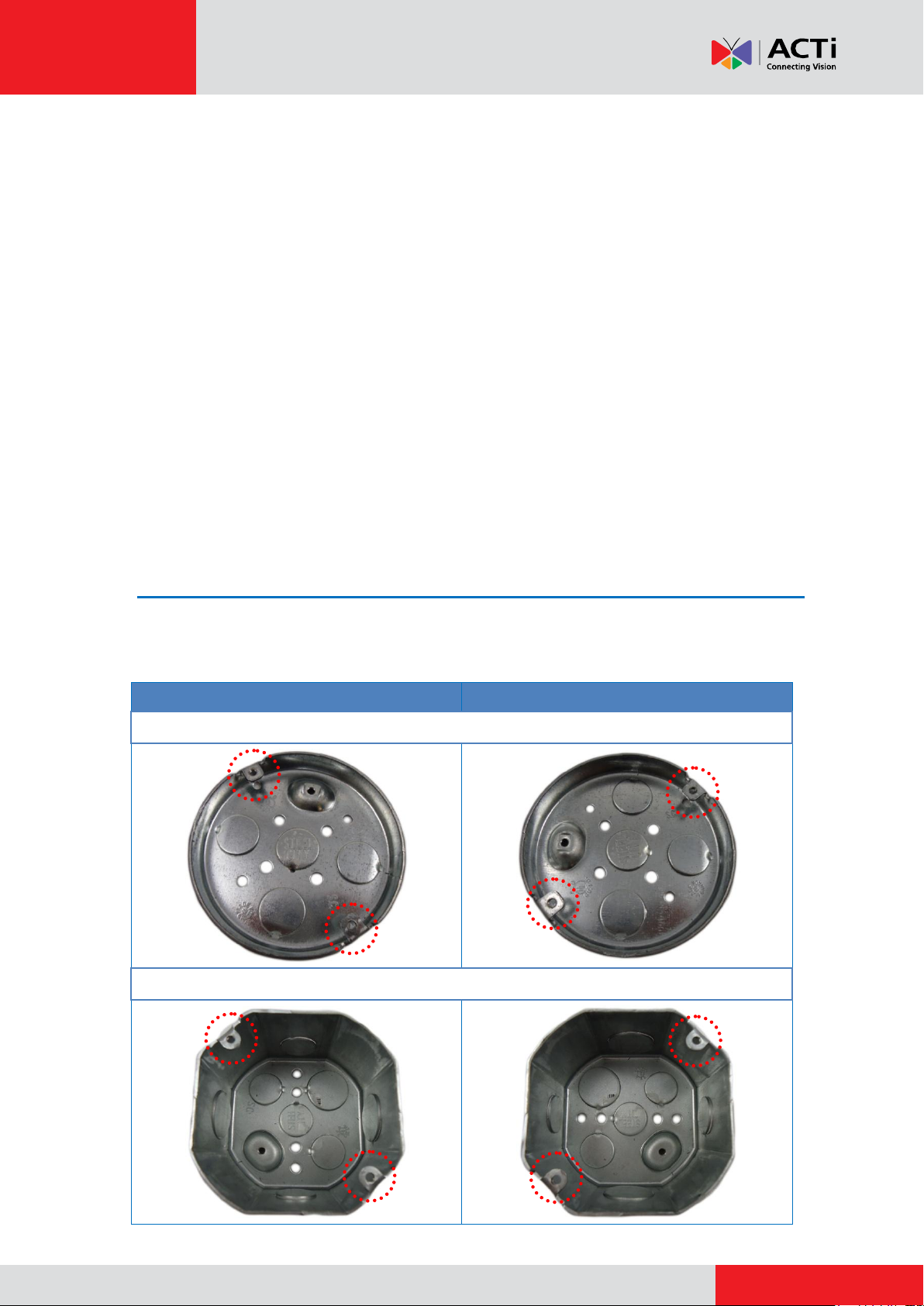
Screw Holes from Left to Right
Screw Holes from Right to Left
4” Round
4” Octagon
Installation Procedures
This section describes the procedures in installing the camera on a 4” Round or 4” Octagon
Gang Box which is mounted on the wall.
With this type of installation, the following accessories and tools are required:
Gang Box (4” round or 4” octagon)
Gang Box Converter (PMAX-0805)
Phillips Screwdriver
Network Cable
For simplicity, most of the camera images used in the succeeding sections were taken using the
camera model with heat sink; same procedures apply to the model without heat sink unless
specified.
Step 1: Install the Gang Box
Before installation, note that the gang box must be installed with either of the following
orientation:
3
www.acti.com
Installation Guide
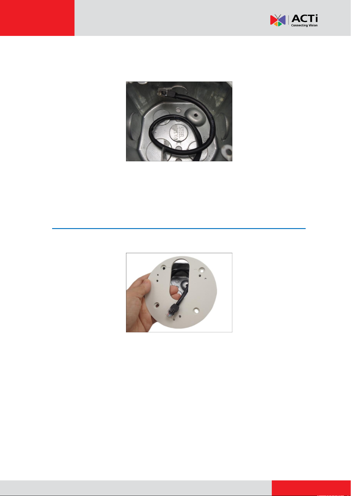
1. Remove a knockout on the gang box to route the network cable.
2. Route the network cable along the surface or inside the surface and into the gang box.
3. Attach the gang box on the surface or inside the surface according to the recommended
orientation above.
Step 2: Install the Gang Box Converter
1. Route the network cable to pass through the hole of the gang box converter.
4
www.acti.com
Installation Guide
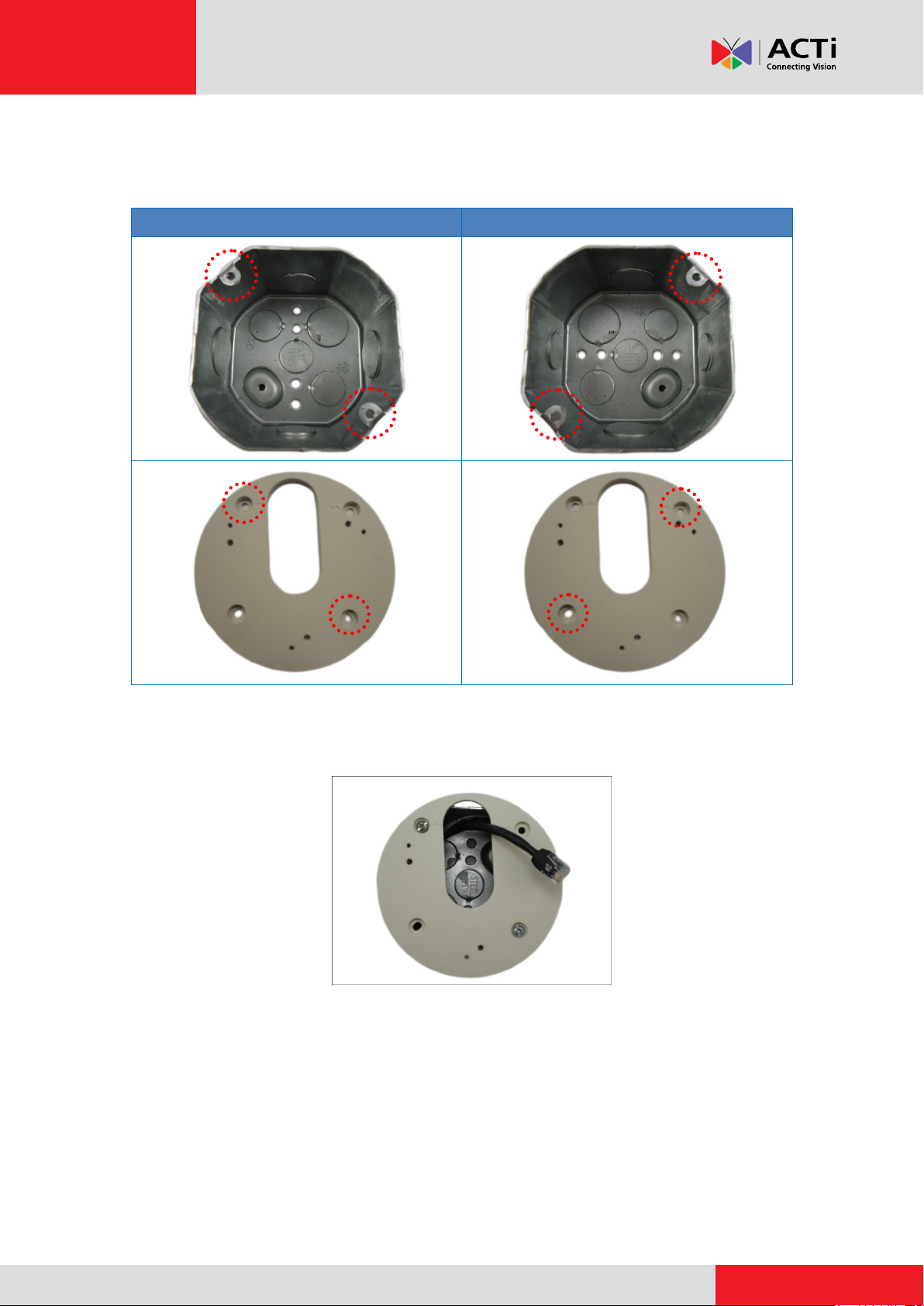
Screw Holes from Left to Right
Screw Holes from Right to Left
2. Install the gang box converter onto the gang box using the screws included in the gang box
package. Note which screw holes to attach to secure the converter to the gang box.
NOTE: Same screw holes apply when using the 4” round gang boxes.
Installed gang box converter example is shown below.
5
www.acti.com
Installation Guide
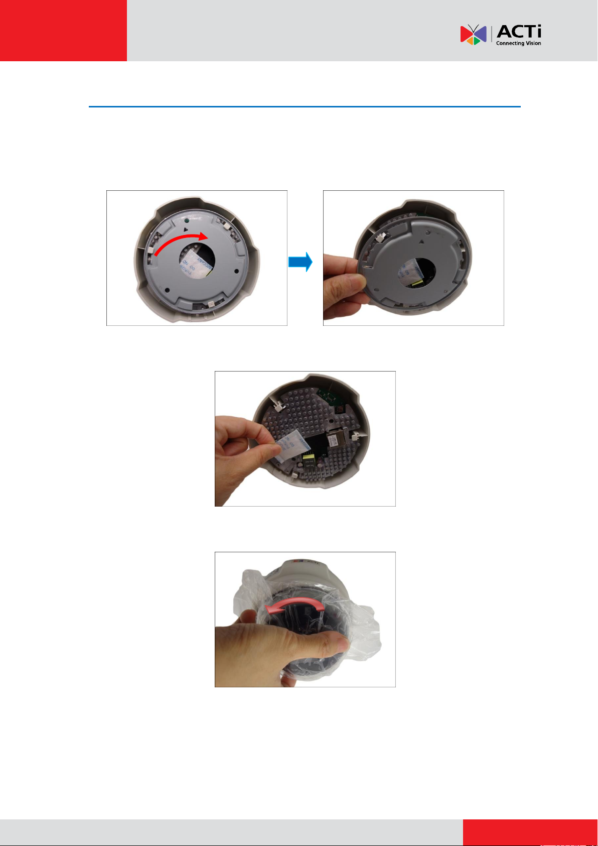
Step 3: Unpack the Camera
NOTE: To avoid scratches or leaving fingerprints on the dome cover, it is recommended to retain
the plastic covering the dome cover until the camera is completely installed.
1. Slide the mounting plate counter-clockwise to detach it from the camera.
2. Remove the silicon bag.
3. Slide the dome cover counter-clockwise to remove the cover from the camera.
6

www.acti.com
Installation Guide
Step 4: Attach the Mounting Plate
1. Route the network cable through the cable hole of the mounting plate.
2. Align the screw holes of the mounting plate to the marked holes on the gang box converter.
3. Attach the mounting plate to the gang box converter using the three (3) screws (included in
the camera package).
NOTE: Make sure the screw is flat on the plate.
7
 Loading...