

ACTi I912 User Manual

Indoor PTZ Camera
Hardware Manual
I91, I92, I912
Ver. 2015/05/28

www.acti.com
Hardware Manual
Table of Contents
Precautions 4
Safety Instructions ........................................................................... 6
Introduction 7
List of Models .................................................................................... 7
Package Contents ............................................................................. 8
Physical Description ........................................................................ 9
Before Installation 10
Unpacking the Camera ................................................................... 10
Preparing the Power Adapter ........................................................ 11
Preparing the DI/DO Connector ..................................................... 13
Installation Procedures 16
Mounting Solutions ........................................................................ 16
Other Mounting Accessories ........................................................ 18
Mounting on the Ceiling ................................................................. 19
Using the Bundled Surface Mount ............................................... 19
Using the Flush Mount ................................................................. 22
Using the Pendant Mount ............................................................. 28
Mounting on Straight Wall ............................................................. 32
Using the L-Type Wall Mount ....................................................... 32
Other Accessories and Adjustments 35
How to Replace the Dome Cover ................................................... 35
How to Reset the Camera............................................................... 36
Accessing Camera 37
Configure the IP Addresses ........................................................... 37
2

www.acti.com
Hardware Manual
Access the Camera ......................................................................... 41
3

www.acti.com
Hardware Manual
Precautions
Read these instructions
Read all the safety and operating instructions before using this product.
Heed all warnings
Adhere to all the warnings on the product and in the instruction manual. Failure to follow the
safety instructions given may directly endanger people, cause damage to the system or to
other equipment.
Servicing
Do not attempt to service this product yourself as opening or removing covers may expose you
to dangerous voltage or other hazards. Refer all servicing to qualified service personnel.
Trademarks
ACTi and ACTi logos are registered trademarks of ACTi Corporation. All other names and
products used in this manual are registered trademarks of their respective companies.
Liability
Every reasonable care has been taken during the writing of this manual. Please inform your
local office if you find any inaccuracies or omissions. ACTi will not be held responsible for any
typographical or technical errors and reserves the right to make changes to the product and
manuals without prior notice.
4

www.acti.com
Hardware Manual
Federal Communications Commission Statement
This equipment has been tested and found to comply with the limits for a
class B digital device, pursuant to Part 15 of the FCC Rules. These limits are
designed to provide reasonable protection against harmful interference in a
residential installation. This equipment generates, uses, and can radiate radio frequency
energy and, if not installed and used in accordance with the instructions, may cause harmful
interference to radio communications. However, there is no guarantee that interference will not
occur in a particular installation. If this equipment does cause harmful interference to radio or
television reception, which can be determined by turning the equipment off and on, the user is
encouraged to try to correct the interference by one or more of the following measures:
Reorient or relocate the receiving antenna.
Increase the separation between the equipment and receiver.
Connect the equipment into an outlet on a circuit different from that to which the
receiver is connected.
Consult the dealer or an experienced radio/TV technician for help.
Warning: Changes or modifications to the equipment that are not expressly approved by the
responsible party for compliance could void the user’s authority to operate the equipment.
European Community Compliance Statement
This product has been tested and found to comply with the limits for Class B
Information Technology Equipment according to European Standard EN 55022
and EN 55024. In a domestic environment, this product may cause radio interference in which
cause the user may be required to take adequate measures.
5

www.acti.com
Hardware Manual
Safety Instructions
Don’t use the power supply with other voltages
This device is likely to be damaged or damage other equipments / personnel, if you use a
power supply with different voltage than the one included with this device. All warranty of this
product will be voided in the situations above.
Cleaning
Disconnect this product from the power supply before cleaning.
Accessories and Repair Parts
Use only the accessories and repair parts recommended by the manufacturer. Using other
attachments not recommended by the manufacturer may cause hazards.
Water and Moisture
Do not use this product near water, for example, near a bathtub, washbowl, kitchen sink, or
laundry tub, in a wet basement, or near a swimming pool and the likes. Install this product as
well as other devices (such as PoE injector, alarm, etc.) in a dry place protected from weather.
Servicing
Do not attempt to service this product yourself. Refer all servicing to qualified service
personnel.
Damage Requiring service
Disconnect this product from the power supply immediately and refer servicing to qualified
service personnel under the following conditions.
1) When the power-supply cord or plug is damaged
2) If liquid has been spilled, or objects have fallen into the product.
3) If the product has been directly exposed to rain or water.
4) If the product does not operate normally by following the operating Instructions in this
manual. Adjust only those controls that are covered by the instruction manual, as an
improper adjustment of other controls may result in damage, and will often require
extensive work by a qualified technician to restore the product to its normal operation.
Safety Check
Upon completion of any service or repairs to this product, ask the service technician to perform
safety checks to determine if the product is in proper operating condition.
6
www.acti.com
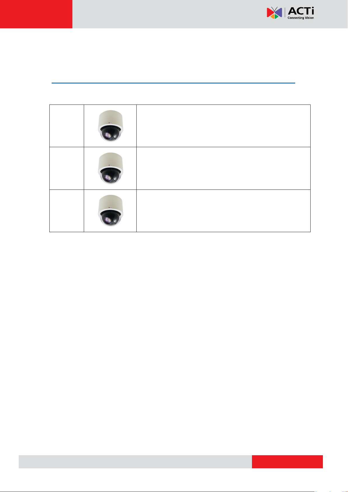
I91
1MP Indoor PTZ with D/N, Extreme WDR, SLLS, 30x Zoom lens
I92
2MP Indoor PTZ with D/N, Extreme WDR, SLLS, 30x Zoom lens
I912
4MP Indoor PTZ with D/N, Advanced WDR, SLLS, 33x Zoom
lens
Hardware Manual
Introduction
List of Models
This hardware manual contains the following models:
7
www.acti.com
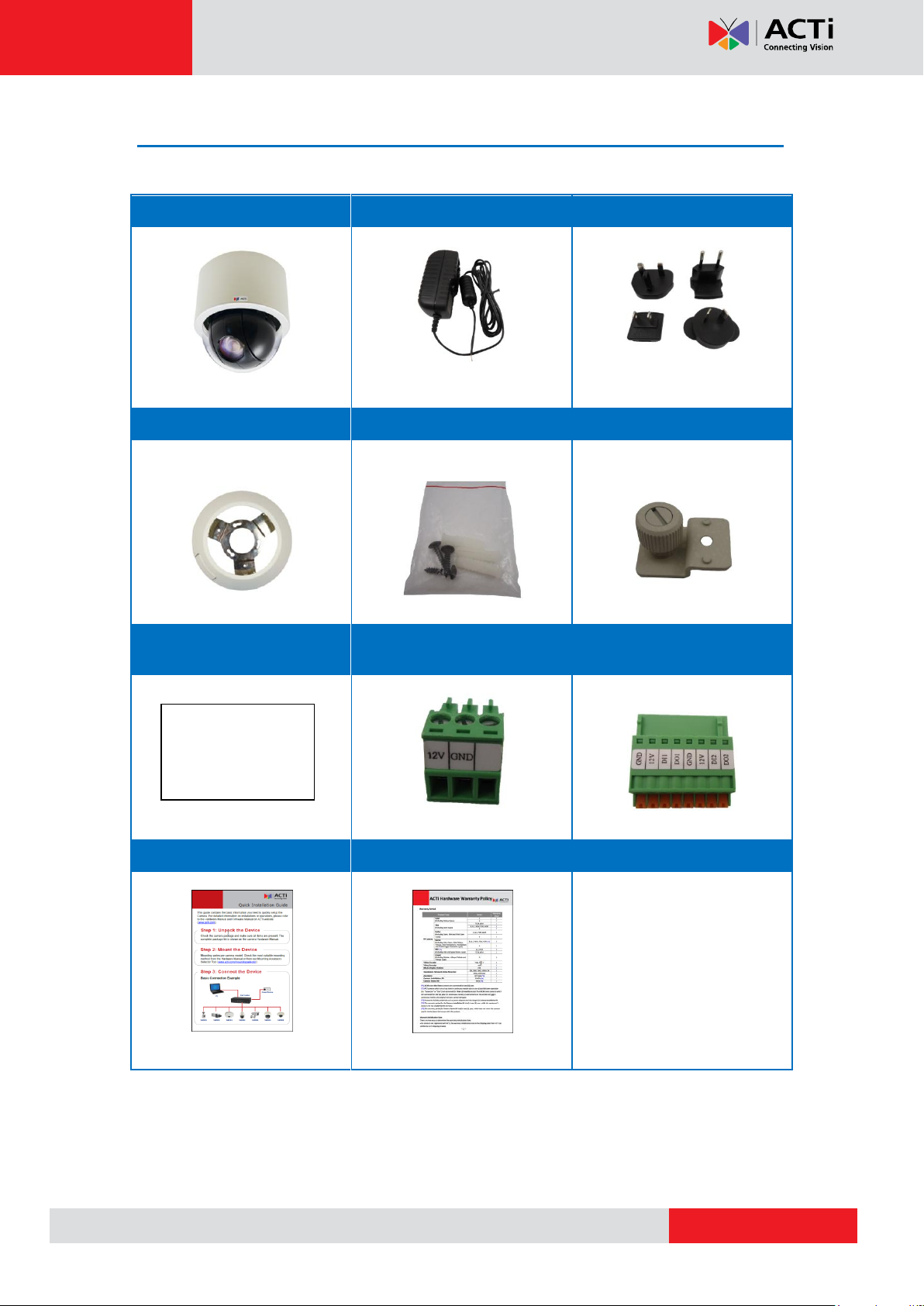
Package Contents
Camera
Power Adapter
Universal Plug Converter
Surface Mount
Mounting Screw Kit
Fixing Bracket
Drill Template
Terminal Block
(for Power)
Terminal Block
(for DIO/DO)
Quick Installation Guide
Warranty Card
Drill Template
Hardware Manual
8
www.acti.com
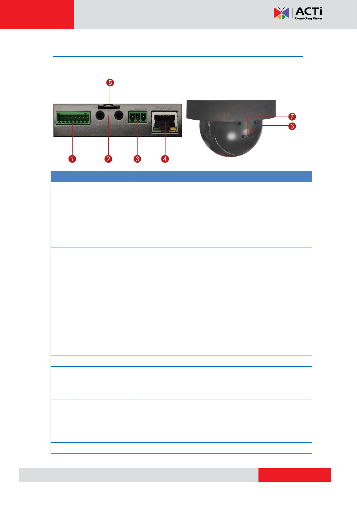
Item
Description
1
Digital Input / Output
(DI/DO)
Connects to digital input or output devices, such as an alarm
trigger, panic button, etc. Digital Input (DI) and Digital Output
(DO) devices are used in applications like motion detection,
event triggering, alarm notifications, etc. Please refer to
Preparing the DI/DO Connector on page 13 for information on
how to connect DI/DO devices to your camera.
2
Audio IN / Audio
OUT Jacks
The Audio IN jack connects to an audio input device, such as a
microphone with built-in amplifier. The Audio OUT jack connects
to an audio output device, such as a speaker.
NOTE: Make sure that the connected audio input device has a
built-in amplifier. Connecting an ordinary microphone will dwarf
sounds and will result in inaudible recording.
3
DC 12V Power Input
In case the camera is connected to a non-PoE (Power over
Ethernet) switch, use this connector to connect the camera to an
external power adaptor. See Preparing the Power Adapter on
page 11 for information.
4
Ethernet Port
Connects to a network using a standard Ethernet cable.
5
Memory Card Slot
For local recording, insert a memory card (not included) into the
slot with the metallic contacts facing down the camera.
NOTE: Supports only microSDHC and microSDXC cards.
6
Reset Button
The Reset Button is used to restore the factory default settings of
the camera, including the administrator’s password. Press and
hold the Reset button for 5 seconds or until the Power LED goes
off. See How to Reset the Camera on page 36.
7
Power LED
The Power LED lights red when the camera is powered up.
Hardware Manual
Physical Description
Connectors View Internal View
9
www.acti.com
Hardware Manual
Before Installation
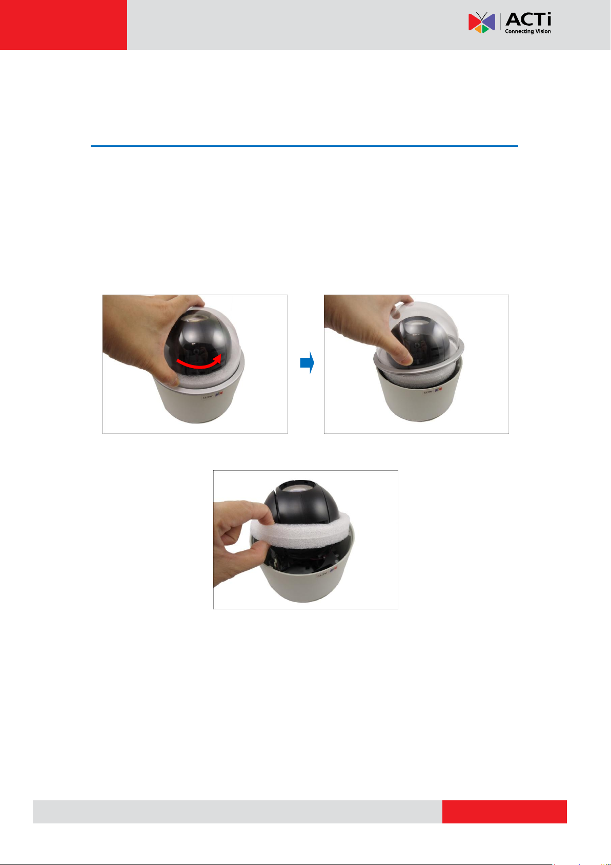
Unpacking the Camera
NOTE: To avoid scratches or leaving fingerprints on the dome cover, it is recommended to
retain the plastic covering the dome cover until the camera is completely installed. However,
the plastic has been removed on the pictures in this documentation to show clarity of the
procedures being described.
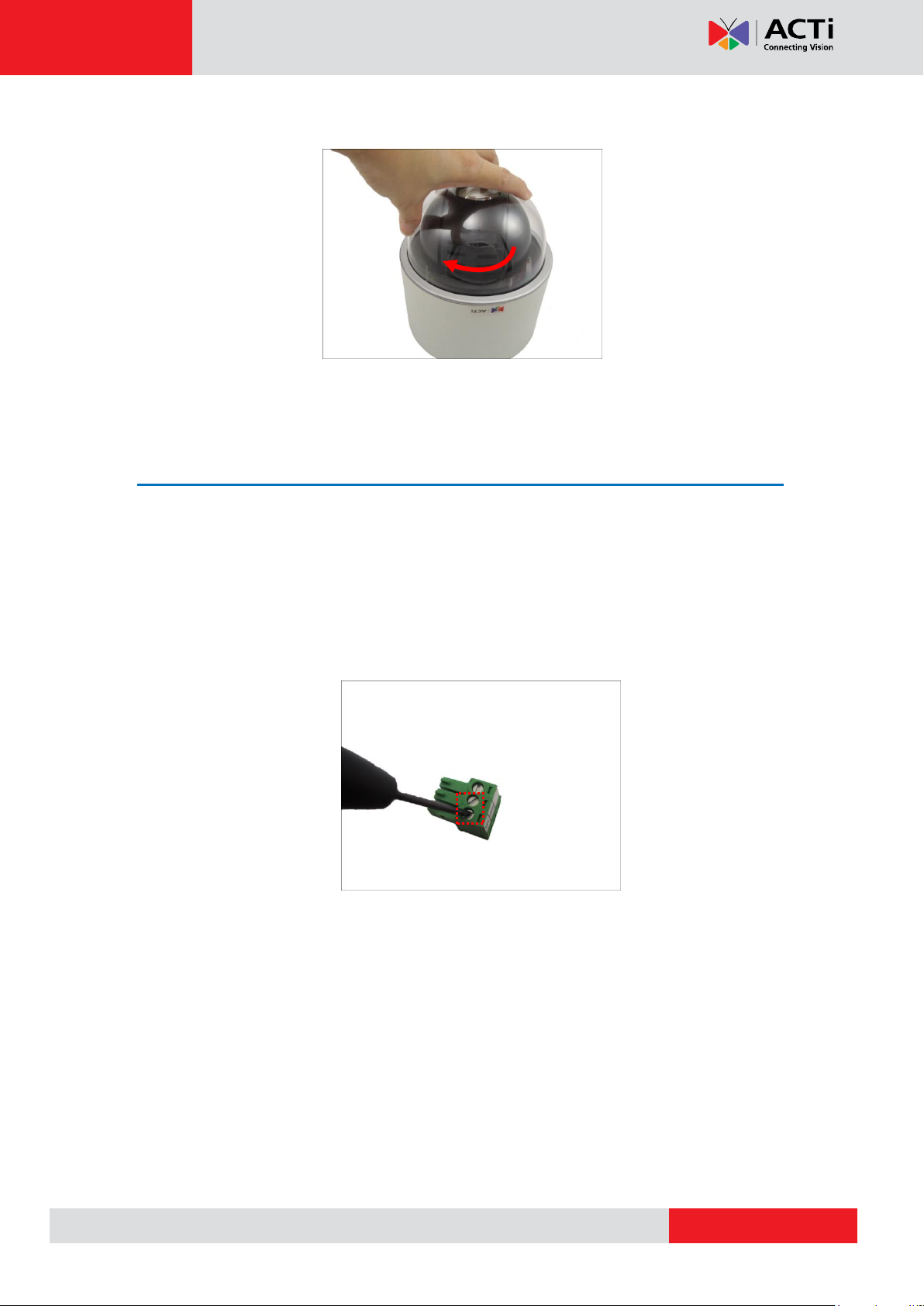
1. Rotate the dome cover counter-clockwise to remove it.
2. Remove the Styrofoam.
10
www.acti.com
Hardware Manual
3. Rotate the dome cover clockwise to attach it.
Preparing the Power Adapter
In case of using a non-PoE switch or your PoE switch has limited power supply, you can use
the bundled power adapter and directly connect the camera to a power outlet. The power
adapter must be connected to the supplied terminal block before use.
To do this, follow the procedures below:
1. Loosen the screws of the 12V and GND pins of the power terminal block.
11
www.acti.com
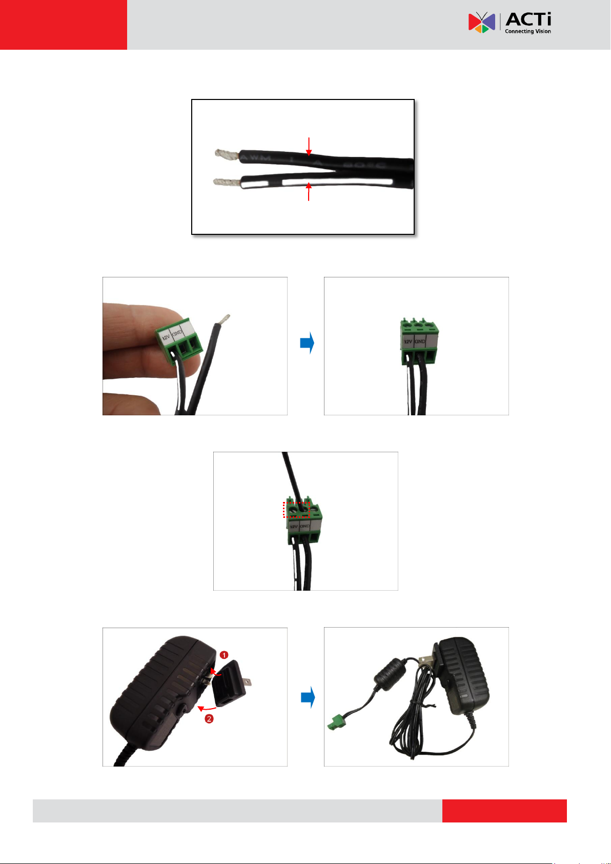
White stripe: Connects to 12V Pin
Connects to GND Pin
Hardware Manual
2. Take note that the power adapter cable has two (2) different wires:
3. Connect the wire with the white stripe to the 12V pin and the other to the GND pin.
4. Tighten the screws of the 12V pin and the GND pins to secure the wire connection.
5. Attach one of the bundled adapter plugs suitable in your location.
12
www.acti.com
Device
Mapping Instructions
Digital Input 1 (DI1)
GND
Connect the wires of the first input device to GND
and DI1.
DI1
Digital Input 2 (DI2)
GND
Connect the wires of the second input device to GND
and DI2.
DI2
Device
Pin
Mapping Instructions
Digital Output 1 (DO1)
12V
Connect the wires of the first output device to 12V
and DO1.
DO1
Digital Output 2 (DO2)
12V
Connect the wires of the second output device to 12V
and DO2.
DO2
Hardware Manual
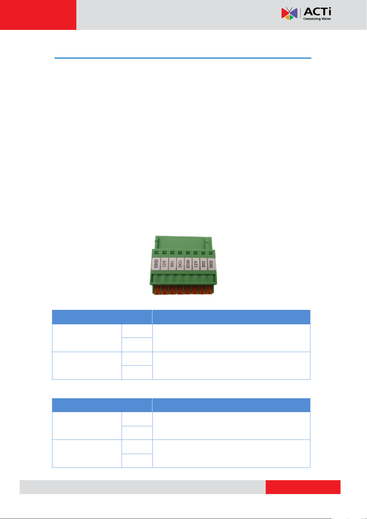
Preparing the DI/DO Connector
Depending on your surveillance needs, you may connect digital input or output devices to your
camera to trigger events or notifications.
Digital Input (DI) devices can be used to notify the camera about an activity in the camera site.
DI can be triggers of events. For example, you can connect a “panic button” to the camera; as
such when the panic button is pressed, the alarm signal will be sent through the camera. Other
common DI device applications are emergency button, smoke detector, passive infrared
sensor, etc.
Digital Output (DO) devices are external devices that are activated by the camera upon an
event inside the camera. For example, you can connect an “alarm horn” to the camera; as
such when an event occurs inside the camera (e.g. detected intruder), the alarm horn will
sound. Other common DO device applications are motion-triggered lights, electric fence,
magnetic door locks, etc.
You can connect up to two DI and two DO devices to your camera.
To connect input devices (DI), map the pins to one of the pin combinations below:
To connect output devices (DO), map the pins to one of the pin combinations below:
13
 Loading...