

Page 1
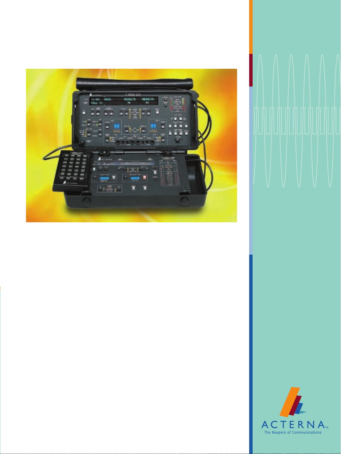
Acterna T-BERD
Channel Access Tester
Product Highlights
• Combines multiple service testing
capabilities in a single test instrument
• Performs extensive testing for services
from DS0 to DS3
• Enables VF circuit testing from a digital
access point
• Provides protocol testing by verifying
both layer 2 and layer 3 communications
for GR-303, ISDN PRI, and SS7 protocols
• Allows remote access and control from
Windows®-based systems
• Includes field-upgradeable software and
hardware options
• Offers an established reputation for reliable testing and proven performance
Application Highlights
• Perform standard T1 BER testing and
signal analysis measurements
• Drop and insert on any of the 24 channels
from any T1 access point
• Scan any combination of the 24 channels
on a T1 circuit for signaling activity and
seize the first active channel for analysis
of digits and supervisory events
• Perform PBX emulation and digit and
events analysis to verify proper switch
translations
• Qualify voice-grade circuits from any digital access point by measuring C-message,
C-notch, 3 kHz flat, 3 kHz-notch, and
signal noise on any PCM channel in the T1
• Qualify STS-1 and DS3 circuits with an
array of BERT patterns for both M13 and
C-bit framing
• Monitor and test DDS circuits from a T1
access point
• Utilize preprogrammed loop codes for
intelligent repeaters to sectionalize span
problems
• Monitor SS7, GR-303, and ISDN PRI
protocols to verify the health of the link
and potential protocol problems
Page 2

To d a y ’s increased network complexity requires constant turn-up testing and troubleshooting for the growing number of
services and protocols. The Acterna Channel Access Tester—a single instrument unmatched in its ability to perform multiple
services testing—tests VF, DDS, FT1, T1, DS3, and STS-1 services as well as ISDN PRI, SS7, and GR-303 protocols. With
more than 13,000 Channel Access Testers in use today, this one, highly reliable test instrument is equally at home in the central
office (CO), the mobile telephone switching office (MTSO), the PBX network center, and the development lab as well as on
the production floor.
Applications
The Channel Access Tester’s mainframe offers flexibility and power that is unmatched by any channel access test set on the
market.
Turn Up and Troubleshoot FT1/T1 Circuits
Users can monitor the status of in-service circuits, troubleshoot out-of-service circuits with a complete set of stress patterns,
and isolate faulty equipment or circuit impairments as well as build a custom set for every testing need with the Channel
Access Tester’s field-upgradeable software options.
T1 BERT Option
The Channel Access Tester mainframe with the T1 BERT Option enables the user to troubleshoot the entire T1 circuit and
test the error tolerance of network equipment by inserting single burst, variable-rate bipolar violations (BPVs), frame errors,
and logic errors. Through automatic configuration and results summary functions, framing, pattern, and error status are
immediately identified. The two transmitters and receivers provide several different test modes that include Terminate, Drop
and Insert, and Dual Receiver Monitoring. While in Dual Receiver Monitoring mode, the user can none intrusively sectionalize
the T1 link; count BPVs, frame errors, and cyclic redundancy checks (CRCs); and measure the receive signal levels (volts,
dBdsx) and frequencies for both T1 inputs. In addition, the test set can be used to terminate the circuit and perform turn-up
and out-of-service troubleshooting using Terminate mode. And by placing the Channel Access Tester in Drop and Insert
mode, the user can test a particular channel out of T1 without affecting the rest of the traffic.
FT1 Option
The FT1 Option allows users to turn-up and troubleshoot contiguous and noncontiguous Nx56 and Nx64 FT1 circuits.
When the Channel Access Tester is placed in Terminate mode, the user can completely qualify and test new FT1 circuits
before connecting customer premises equipment (CPE). In addition, the test set has drop and insert capabilities and a full
complement of T1 and DDS test patterns for troubleshooting FT1 circuits. And similar to the T1 BERT Option, the FT1
Option inserts single, burst, or variable-rate BPVs and logic errors across the fractional bandwidth.
Advanced Stress Patterns Option
The Advanced Stress Patterns Option allows the user to test T1, FT1, and DDS networks with a variety of stress patterns
including DDS-5, DDS-6, T1-2/TRIP, T1-3, T1-4, T1-5, T1-6, 55 octet, and T1-DALY. These advanced stress patterns help to
verify the good health of the link and confirm that it is able to sustain the quality of service required.
G.821 Option
The G.821 Option provides the measurement of the G.821 results, including severely errored seconds, percentage of severely
errored seconds, degraded minutes, percentage of degraded minutes, unavailable seconds, percentage of availability, and consecutive severely errored seconds. These advance measurement results give the user greater insight into the link performance
and can indicate marginal problems that have the potential to cause future problems.
Smart Loopback/Command Codes Option
The Smart Loopback/Command Code Options supports a variety of intelligent equipment, enabling the Channel Access
Tester to use preprogrammed loop codes for intelligent repeaters, which can help sectionalize span problems before dispatching maintenance personnel.
This options also allows the user to query performance monitoring NIU equipment, use loopable repeater technology to
qualify and maintain outside plant T1 spans, and retrieve in-service performance data to verify remote circuit operation. By
sending and receiving commands for maintenance switch operation, the user can minimize circuit downtime and query
performance data.
1
Page 3
Caller ID Option
MON
Out
In
DSX-1
A-Side
Z-Side
T-BERD Channel
Access Tester
COT/
Switch
Remote
Terminal
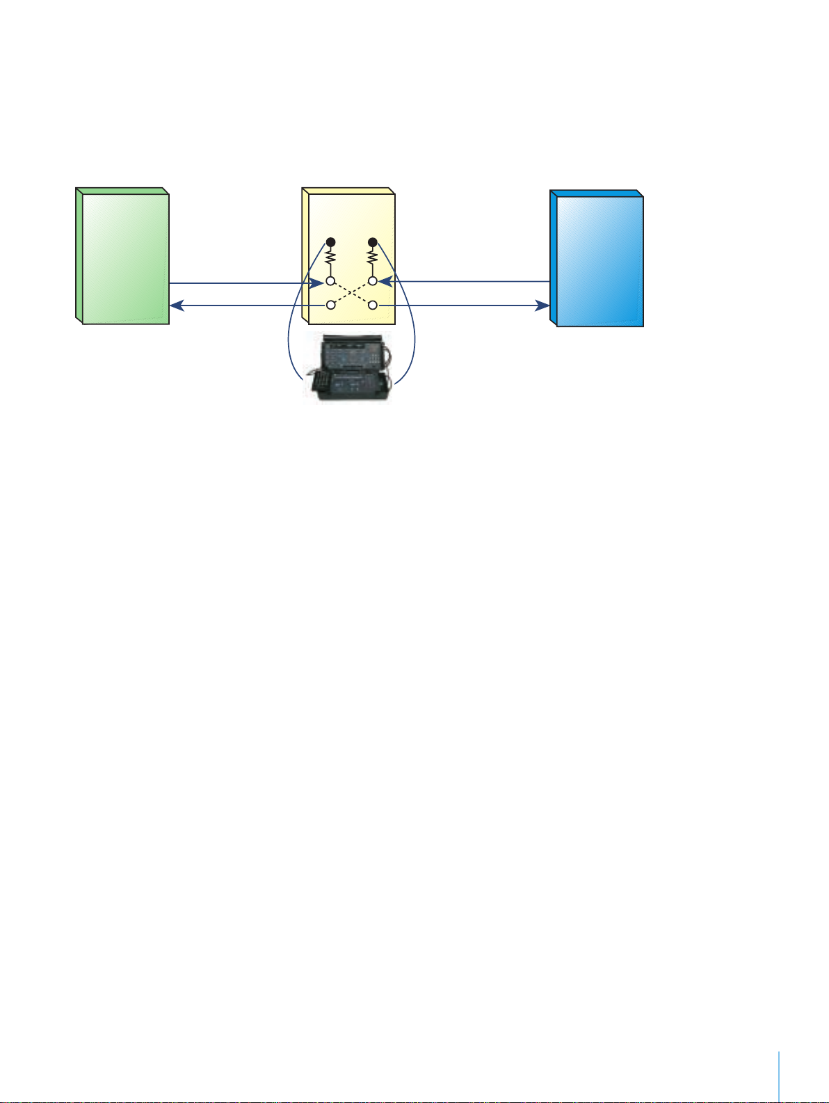
The Caller ID Option enables the Channel Access Tester to verify caller ID performance from a T1 access point by monitoring
caller ID FSK data; scanning preselected T1 channels for the first ringing activity to resolve intermittent caller ID problems;
measuring frequency, level, and timing parameters; and calculating and comparing checksums to verify caller ID data. Access
from the T1 can improve turn-up efficiency and decrease unnecessary dispatches to the field.
Caller ID
Test SLC Systems
Enhanced ESF/SLC Option
The Enhanced ESF/SLC Option adds testing flexibility to the network. It enables the Channel Access Tester to capture and display embedded data link information for complete ESF and SLC-96 circuit testing; receive and transmit one-second broadcasts
generated by ESF CSUs and other equipment; perform full-duplex error analysis from a single T1 access point; and nonintrusively
capture shelf alarms, far-end loops, line protection switching, and maintenance events on SLC-96 circuits.
The Channel Access Tester with ESF capabilities allows for:
• Decoding, displaying, and transmitting performance report messages for ESF circuits
• Measuring far-end BPVs and frame and CRC errors
• Transmitting one-second broadcast messages generated by ESF CSUs and other equipment
The Channel Access Tester with SLC capabilities allows for:
• Decoding, displaying, and transmitting alarms, protection switching, loop commands, and ringing signals for SLC-96
(modes 1 and 2) and SLC Series 5 circuits
• Capturing, nonintrusively, shelf alarms, far-end loops, line protection switching, and maintenance events on SLC-96 circuits.
Turn Up and Troubleshoot DDS Circuits
DDS Option
The DDS Option provides the flexibility to monitor and test DDS circuits from a T1 access point using Dual-receiver
Monitoring, Drop and Insert, and Terminate modes. By measuring the round-trip path delay of any channel in the T1, the
user can verify that excessive circuit delays do not impact circuit performance. Moreover, this option offers testing of both
DS0A and DS0B formatted DDS circuits at rates from 2.4 kbps to 64 kbps. When turning up and troubleshooting circuits,
users can loop DDS circuits using alternating and latching OCU, DSU, and other loop codes, which allows them to test DDS
circuit using various test patterns such as Bellcore standard DDS stress patterns (DDS-1 through DDS-6). By inserting single,
burst, or variable-rate BPVs and frame and logic errors, the user can test the physical layer at various subrates.
2
Page 4
Perform Signaling and Digit Analysis
Signaling Option
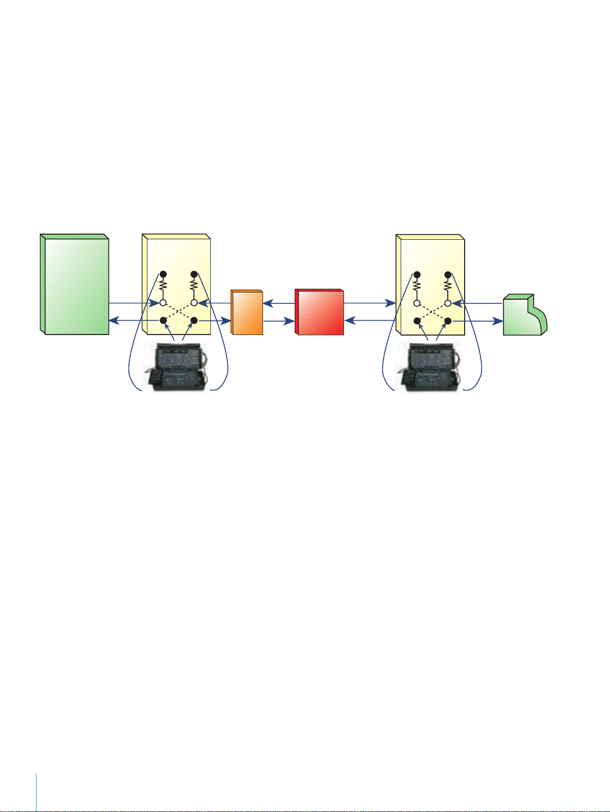
The Signaling Option enables the Channel Access Tester to test the ability of a switch/PBX to handle incoming calls and emulate
switch-to-switch communications. Additionally, in Dual-receiver Monitoring mode, the Channel Access Tester can nonintrusively capture and display all digits and supervision events without preprogramming sequences. The Digit Analysis Option
adds the capability to analyze the captured information such as wink timing, inter-digit timing, and digit frequency and level.
The combination of these two Options allows the user to send and receive DTMF, MF, or DP digits to and from switches and
PBXs. In addition, the Channel Access Tester can scan any combination of the 24 channels on a T1 circuit for signaling activity
and seize the first active channel for analysis. Once the physical link is verified, with these two Options the user can dial up
and test the service on VF circuits.
This level of extensive testing ensures that proper PBX and switch operation can be verified through call origination, call
termination, verification signaling, and in-depth event and digit measurements.
Switch
Signaling
DSX-1
A-Side
T-BERD Channel
Z-Side
MON
Out
In
Access Tester
NIU
CSU
DSX-1
A-Side
T-BERD Channel
Z-Side
MON
Out
In
Access Tester
PBX
Test Voice and Data-Grade Voice Frequency Circuits
Voice Frequency Option
The Voice Frequency (VF) Option tests voice or data grade VF circuits from a T1 access point and provides a full range of testin
functions for complete circuit analysis. With this option, the user can qualify voice-grade circuits from any digital access poin
by performing loss and signal noise measurements on any of the 24 channels within T1. When equipped with the VF Option,
the Channel Access Tester can perform peak-to-average ratio (P/AR) and frequency sweep tests to determine if data-grade
circuits meet engineering specifications. In addition, this Option allows the user to measure echo return loss on voice-grade
PCM channels to determine the magnitude of talker echo. The user can carry out three-tone slope and other loss measurements
using various filters (C-message, C-notch, 3 kHz flat, 3 kHz-notch), using drop and insert on any T1 channel while maintaining
service on the remaining channels.
g
t
Perform SS7 Protocol Analysis
SS7 Call Trace Option
The SS7 Call Trace Option allows the Channel Access Tester to monitor the SS7 link by decoding layer 2 and layer 3 link statistics
and information. Performing two tasks—link statistics and call trace—this option is an ideal tool for performing in-service
troubleshooting of protocol translations from the access network. When equipped with this option, the Channel Access
Tester is able to continuously monitor the health of the SS7 link as well as track all call processing messages.
When performing the link statistics task, the Channel Access Tester nonintrusively monitors all SS7 layer 2 messages. The
results provide information about the percentage of utilization, FCS errored packet count, and message signal unit (MSU),
link status signal unit (LSSU), and fill-in signal unit (FISU) packet counts. Call trace allows the user to trace and display call
processing messages and expertly report a thorough range of layer 3 SS7 messages that include called state, called number, calling
number, call type, network identification, call origination source, call disconnect source, and cause values. By verifying link
traffic and usage, the user is able to isolate transmission and protocol problems between service switching points (SSP), signal
transfer points (STP), and service control points (SCP) in the SS7 network.
3
Page 5
Analyze Primary Rate ISDN
Switch
MON
Out
In
DSX-1
A-Side
Z-Side
T-BERD Channel
Access Tester
Remote
Terminal
(TR-303)
SONET
COT/Mux
Primary Rate ISDN Option
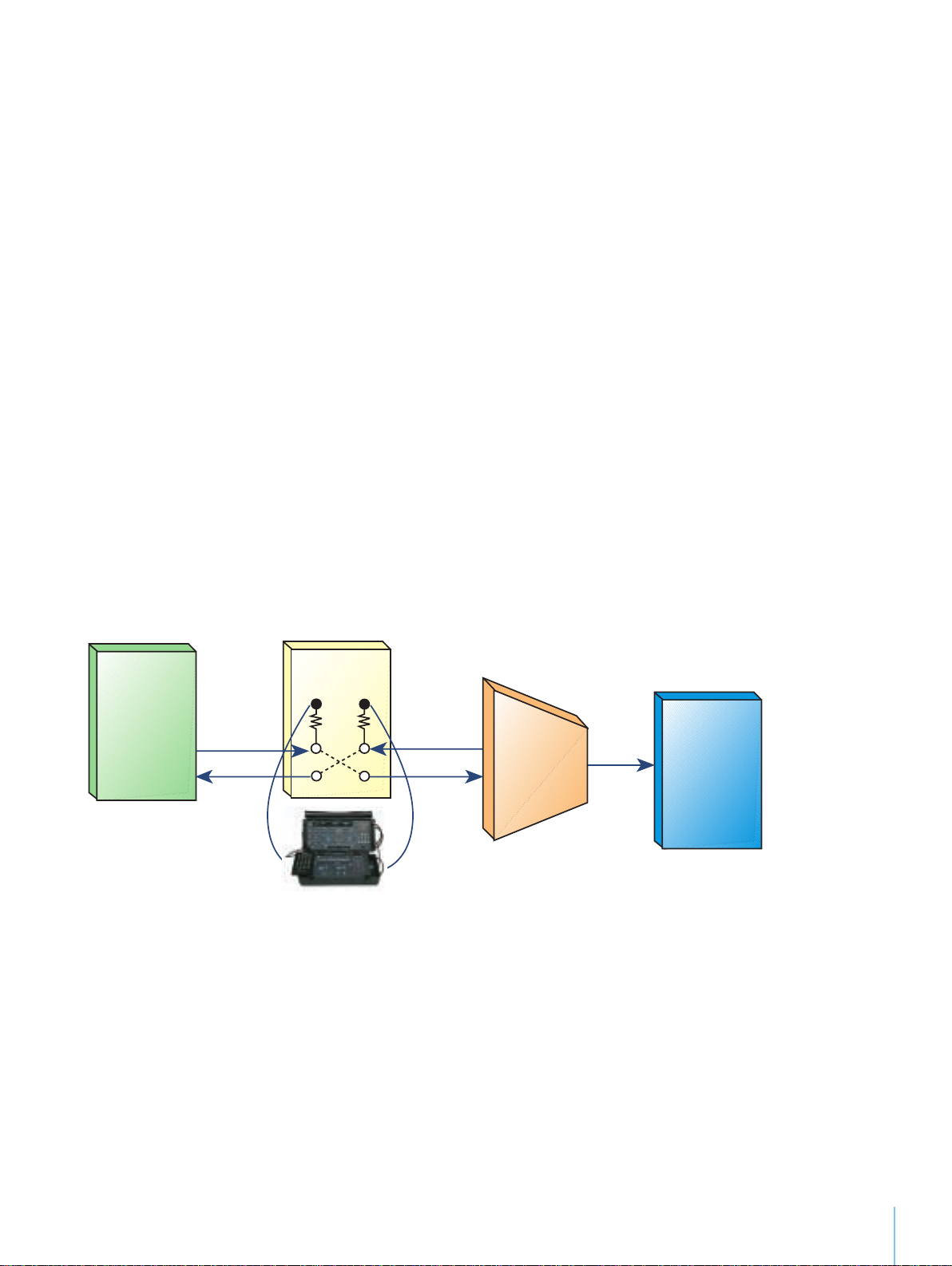
The Primary Rate ISDN Option allows the Channel Access Tester to nonintrusively monitor link statistics over ISDN PRI
networks as well as perform call tracing over the ISDN D-channel. When equipped with this option, the Channel Access
Tester can monitor layer 2 (LAPD) and layer 3 (Q.931) cause code messages on the D-channel, verify that a call is successfully
established, or determine why a call was not completed by examining the protocol cause values. Much like the SS7 Call Trace
Option, the ISDN PRI Option consists of two tasks: link statistics and call trace.
During the link statistics task, the Channel Access Tester nonintrusively monitors all layer 2 (LAPD) messages on the ISDN
PRI D-channel. Test results provide information about the packets on each line and classify them as good, CRC errored, or
discarded as well as provide counts for all information and receiver-ready packets. The call trace task, based on decoding
layer 3 messages, enables the user to trace and display call processing messages and report cause value messages associated
with disconnected calls. The user is able to filter ISDN calls by call type, calling number, and/or called number and verify
why a call was not completed by examining the protocol cause values.
Analyze GR-303 Protocol
GR-303 Option
The GR-303 Option allows the Channel Access Tester to monitor link statistics and perform call tracing over integrated and
digital loop carrier (IDSL) from a DS1 access point. This Option also consists of the link statistics and call trace tasks.
The link statistics task enables the Channel Access Tester to monitor all layer 2 (LAPD) messages on the timeslot management
channel and embedded operations channel. Test results count packets on each line and classify them as good, CRC errored,
or discarded as well as report CRC errored seconds and error rate. In addition, information frames and receiver ready frames
are captured and counted so that a specific SAPI/TEI, EOC logical link operation can be verified. During the call trace task,
the user can verify that a call is successfully established or determine why a call was not completed by examining call state
and protocol cause values. Test results provide information about call state, line value, call type (POTS or ISDN BRI),
DS1/DS0 assignment, origination, and disconnect source as well as cause values that display why or how the call was disconnected.
TR-303 Monitoring
Test Circuits Remotely
DTM32 Option
DTM32 is a Windows-based software program that emulates the Channel Access Tester front panel in real time, allowing the
user to remotely control the test set from the PC or access it from a remote site. This presents a cost-effective platform for
wide area transmission tests and extends the reach of the field technicians.
DTM32 saves on training costs, too, enabling centrally located technicians to perform comprehensive tests at remote locations,
which allows network problems to be resolved rapidly.
4
Page 6
Hardware Option
SONET/DS3 Analyzer Lid
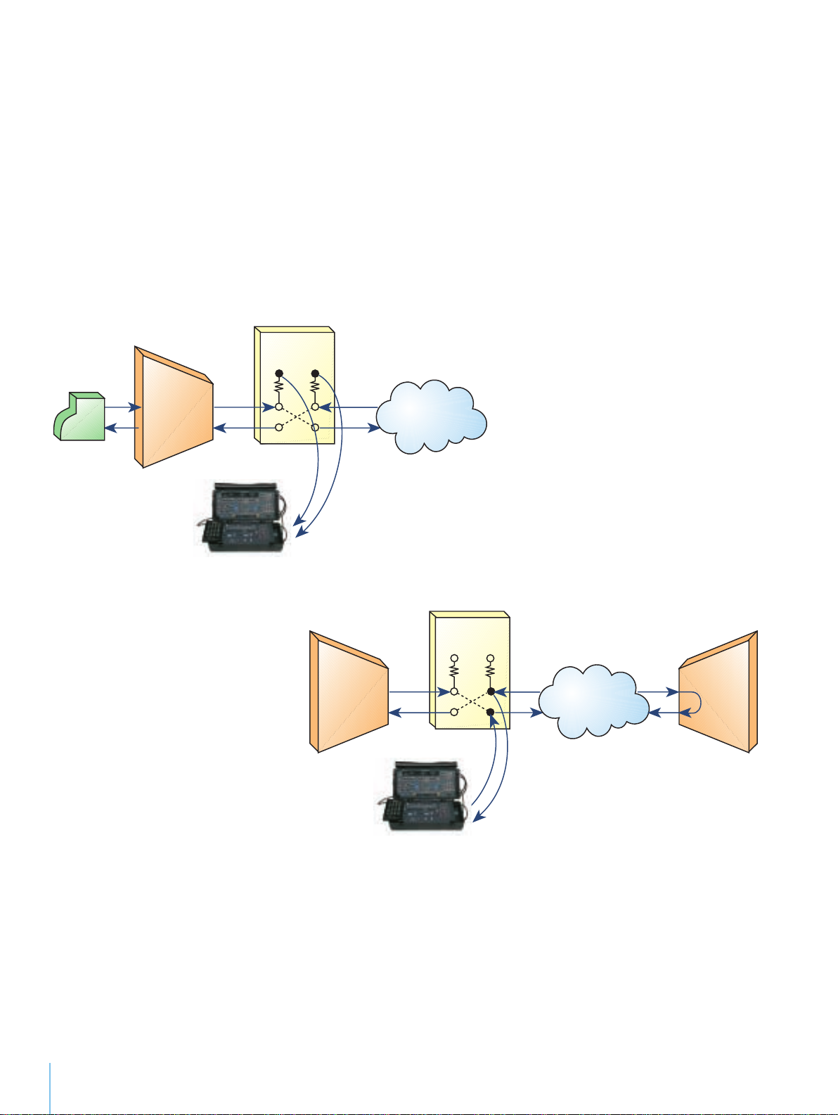
The SONET/DS3 Analyzer Option Lid enables the Channel Access Tester to quickly and easily test STS-1 (52 Mbps) and DS3
(45 Mbps) networks down to the DS1/DS0 level and adds STS-1/DS3 testing to the test set’s robust DS1/DS0 testing capabilities.
While in the field, the user can quickly and easily attach the lid to the Channel Access Tester’s front panel without increasing
the size of the mainframe.
Dual STS-1 and DS3 receivers make analyzing the signal in both directions easy by enabling the user to scan and automatically
detect the signal type and framing format on both the primary and secondary receivers. With this lid the Channel Access
Tester can drop selected DS1s or VT1.5s from incoming STS-1 or DS3 signals to the Channel Access Tester mainframe for
DS1/DS0 analysis. In addition, the Channel Access Tester can insert a DS1 from the mainframe into a selected DS1 or VT1.5
on a STS-1 or DS3 signal. To verify the continuity of the link, the user can place the test set in Terminate mode to insert and
detect STS-1 and DS3 alarms and errors as well as to transmit and receive SONET path trace messages.
STS-1/DS3
MON
PBX
Mux
T-BERD Channel
Access Tester
Out
In
Network
SONET/DS1/DS0 Testing
from STS-1/DS3 Access
STS-1/DS3
Mux
MON
Out
In
Network
Mux
T-BERD Channel
Access Tester
5
BER Testing at STS-1/DS3
Page 7

Ordering Information
Options
220V Option
Channel Access Tester
224V
Channel Access Tester SONET/DS3
11425
ZBTSI Framing Option
11704
Enhanced ESF/SLC Option
11772
RS223/449/V.35 Data Port
12042
Advanced Stress Pattern Option
12708
Digit Analysis Option
12710
SS7 with Call Trace Option
13466
Fractional T1 Option
13467
DDS Option
13963
Smart Loopback Command Codes
13964
Caller ID Option
14875
Primary Rate ISDN Option
41249
RS232/V.35 DSU Data Port
41441
RS232/449 DSU Data Port
41502
VF Option
41934
Signaling Option
41934-SW
Signaling Option for use with 224-1
42659
DSP Option Board
Accessories
224-LID
TB224 Replacement Lid
CC-41306
TB224 Soft Carrying Case
224 DS1/DS3 CB PKG
Channel Access Tester Cable Package
RM-41444-01
TB224, 19” Rack Mount
RMX-41444-02
TB224, 19” to 23” Rack Mount Extender
RM-42138
Signaling Lid, 19” Rack Mount
41404
Side Panel Cover Plate
6
Page 8

Technical Specificitions
Mainframe and T1 BERT
Dimensions and Weight
Overall Dimensions . . . . . . . . . . . . . . . . . . . . . . . .6.5 x 14 x 11 in
. . . . . . . . . . . . . . . . . . . . . . . . . . . . . . . . . .(16.5 x 35.6 x 27.9 cm)
Weight . . . . . . . . . . . . . . . . . . . . . . . . . . . . . . . . . . . .14 lbs (6.4 kg)
Environment
Temperature Range . . . . . . . . . . . . . . . . . . . .0 to 45°C (operating)
. . . . . . . . . . . . . . . . . . . . . . . . . . . . . . . . . . . .-40 to 70°C (storage)
Internal Clock
External Clock (BNC Connector)
Oscillator Accuracy
1.544 MHz ±5 ppm
Frequency Measurement
1 Hz resolution; ±5 ppm accuracy
Signal Loss
No pulse detected for 150 ms
Power Requirements
115/230 VAC ±10%
Operating Modes
Automatic configuration to incoming D4, SLC®-96, ESF, and
1
EFSz
framing
T1 Framed:
D1D
D2
D3/D4
SLC-96
ESF
1
ESFz
4
ESF/D
T1 Test Loopback
T1 Line Loopback
1
Requires ZBTSI Option.
2
Requires T1 BERT Option.
Test Patterns
2
All Ones
All Zeros
Min/Max
23
-1
2
20
-1
2
15
-1
2
15
-1 INV
2
QRSS
3 in 24
1:7
Auto Configuration
Insert Sources (Mainframe Only)
1004 Hz
VF Interface
DS0 Interface
Input/Output Connectors
Line 1:
WECO 310, Bantam
Line 2:
WECO 310, Bantam
Transmit Timing Sources
Recovered Clock (Line 1 or 2)
Excess Zeros
16 or more consecutive zeros are detected
Frame Loss Sync
D1D, D2:
2 frame errors out of 4 frame bits
D3/D4, SLC-96:
2 frame errors out of 4 frame bits
ESF, ESFz
1
:
2 frame errors out of 4 frame bits
Pattern Sync Loss
250 or more errors are detected in 1000 or fewer bits
B8ZS
Code is not detected for 150 ms
Yellow Alarm
D1D, D2, D3/D4, and SLC-96 declared when bit
2 set to “0”for 255 consecutive DS0 channels
Alarm Indication Signal (AIS)
2048 consecutive confirmed ones
T1 Level Measurement
+6.0 dBdsx to -40.0 dBdsx:
+6.0 to -6.0: 0.1 dB resolution
-6.0 to -40.0: 0.5 dB resolution
+23.0 dBm to -23.5 dBm:
0.1 dBm resolution
+7.0 dBm to -13.5 dBm:
0.5 dBm resolution
+12.0 to +0.05 V p-p:
0.01 V p-p resolution
Remote Control
RS-232
IEEE-488
3
VF Interfaces
2-wire:
Connectors: Metallic Posts (for butt set)
4-wire:
Connectors: WECO 310 jacks
Impedance:
600 ohms
7
Page 9

DS0 Interface
Bipolar Data Connectors:
Bantam jacks
Clock Output Connectors:
9-pin D female
64 kHz Bit and 8 kHz Byte Clocks:
TTL and differential outputs
3
Requires IEEE-488 Option.
SONET/DS3 Analyzer Option
Dimensions and Weight
Overall Dimensions . . . . . . . . . . . . . . . . . . . . . . . . .6.5 x 14 x 3 in
. . . . . . . . . . . . . . . . . . . . . . . . . . . . . . . . . .(16.5 x 35.6 x 7.62 cm)
Weight . . . . . . . . . . . . . . . . . . . . . . . . . . . . . . . . . .1.5 lbs (0.85 kg)
Environment
Temperature Range . . . . . . . . . . . . . . . . . . .0 to 45 °C (operating)
. . . . . . . . . . . . . . . . . . . . . . . . . . . . . . . . . . .-40 to 70 °C (storage)
Power Requirements
Powered by mainframe
Operating Modes
Automatic configuration to STS-1 and DS3 signals with the
framing and payload types listed below:
STS/DS3-M13
STS/DS3-C-bit
STS/VT1.5
DS3-M13
DS3-C-bit
DS3-Unframed
Test Patterns/Formats
23
2
-1
20
2
-1
15
2
-1
1010 (Blue)
1100 (Idle)
All Ones
Muxed
DS1 Drop & Insert
DS3:
Internal
Recovered
Oscillator Accuracy
STS-1:
51.840 MHz (center) ±6 ppm, payload ±130 ppm
DS3:
44.736 MHz (center) ±6 ppm
DTM
T-BERD 224 Requirements
Rev. E software or greater
PC Requirements
Windows® Operating System:
Microsoft Windows 3.1 or greater
Personal Computer:
IBM-compatible PC
4 MB RAM
VGA or SVGA monitor (16 color recommended)
Modem Support:
Hayes-compatible modem (AT command set)
1200 baud minimum
9600 baud maximum
®
RTM
T-BERD 224 Requirements
Rev. F software or greater
Workstation Requirements
Hardware:
SUN SPARC station II or higher
16 MB RAM
10 MB disk space
15 in monitor capable of 8-bit color at 1152 x 768
LAN/WAN server for remote access (optional)
Software:
SUN OS 4.1.x (Solaris 1.1.x)
X11/R4 or higher
OSF/Motif 1.2 or higher
Modem Support:
Hayes-compatible modem (AT command set)
1200 baud minimum
9600 baud maximum
Input/Output Connectors
Primary Rx, Secondary Rx, and Transmitter:
WECO 560A jacks
DS1 Bits Clock:
Bantam
Transmit Timing
STS-1:
Internal
Recovered
DS1 Bits
Note: Specifications, terms, and conditions are subject to change without notice.
© Copyright 2001 Acterna, LLC.All rights reserved. Acterna, The Keepers of
Communications, and its logo are trademarks of Acterna, LLC. All other trademarks
and registered trademarks are the property of their respective owners.
8
Page 10

9
Page 11

10
Page 12

Global Headquarters
20400 Observation Drive
Germantown, Maryland 20876-4023 USA
Toll Free 1-800-638-2049
Tel +1-301-353-1550
Fax +1-301-444-8468
www.acterna.com
Note: Specifications, terms, and conditions are subject to change without notice.
© Copyright 2001 Acterna, LLC.All rights reserved. Acterna, The Keepers of
Communications, and its logo are trademarks of Acterna, LLC. All other trademarks
and registered trademarks are the property of their respective owners.
Regional Sales Headquarters
North America
20400 Observation Drive
Germantown, Maryland 20876-4023 USA
Toll Free 1-800-638-2049
Tel +1-301-353-1550
Fax +1-301-444-8468
Latin America
Av. Eng. Luis Carlos Berrini
936 8/9. Andar
04571-000 Sao Paulo, SP
Brazil
Tel +55 11 5503 3800
Fax +55 11 5505 1598
Asia/Pacific
42 Clarendon Street
PO Box 141
South Melbourne, Victoria 3205
Australia
Tel +61 3 9690 6700
Fax +61 3 9690 6750
Acterna is present in more than 80 countries. To find your local sales office, go to www.acterna.com
Western Europe
Arbachtalstrasse 6
72800 Eningen u.A.
Germany
Tel +49 7121 86 2222
Fax +49 7121 86 1222
Eastern Europe, Middle East & Africa
Elisabethstrasse 36
PO Box 13
2500 Baden
Austria
Tel +43 2252 85 521 0
Fax +43 2252 80 727
st
1
Neopalimovskiy Per. 15/7 (4thfloor)
119121 Moscow
Russia
Tel +7 095 248 2508
Fax +7 095 248 4189
TB224/A/DS/LL/SAN/08-01
 Loading...