

Page 1

SDA Series
Stealth Digital Analyzer
Operation Manual
6510-00-0442, Rev D
May 2001
Page 2

Notice
Every effort was made to ensure that the information in this document was accurate at the
time of printing. However, information is subject to change without notice, and Acterna
reserves the right to provide an addendum to this document with information not available at
the time that this document was created.
Copyright
© Copyright 2001 Acterna, LLC. All rights reserved. Acterna, The Keepers of Communications, and its logo are trademarks of Acterna, LLC. All other trademarks and registered
trademarks are the property of their respective owners. No part of this guide may be reproduced or transmitted electronically or otherwise without written permission of the publisher.
Trademarks
Acterna and Stealth Digital Analyzer™ are trademarks or registered trademarks of Acterna
in the United States and/or other countries.
Acterna and PathTrak™ are trademarks or registered trademarks of Acterna in the United
States and/or other countries.
Acterna and DigiCheck™ are trademarks or registered trademarks of Acterna in the United
States and/or other countries.
Specifications, terms, and conditions are subject to change without notice. All trademarks
and registered trademarks are the property of their respective companies.
Ordering information
This guide is a product of Acterna's Technical Information Development Department, issued
as part of the
SDA Series Operation Manual. The ordering number for a published guide is
6510-00-0442, Rev D.
Global Headquarters
20400 Observation Drive
Germantown, Maryland 20876-4023 USA
Toll Free 1-800-638-2049 • Tel +1-301-353-1550 • Fax +1-301-353-0234
www.acterna.com
Page 3

Federal Communi cations Commission (FCC) Notice
This product was tested and found to comply with the limits for a Class A digital device, pursuant to Part 15 of the FCC Rules. These limits are designed to provide reasonable protection against harmful interference when the equipment is operated in a commercial
environment. This product generates, uses, and can radiate radio frequency energy and, if
not installed and used in accordance with the instruction manual, may cause harmful interference to radio communications. Operation of this product in a residential area is likely to
cause harmful interference, in which case you will be required to correct the interference at
your own expense.
The authority to operate this product is conditioned by the requirements that no modifications be made to the equipment unless the changes or modifications are expressly approved
by Acterna.
Industry Canada Re quirements
This Class A digital apparatus complies with Canadian ICES-003.
Cet appareil numérique de la classe A est conforme à la norme NMB-003 du Canada.
EMC Directive Com pliance
This product was tested and conforms to the EMC Directive, 89/336/EEC as amended by
92/31/EEC and 93/68/EEC for electromagnetic compatibility. A copy of the Declaration of
Conformity is provided in this manual.
Low Voltage Directive Compliance
This product was tested and conforms to the Low Voltage Directive, 73/23/EEC as amended
by 93/68/EEC. Conformity with this directive is based upon compliance with the harmonized
safety standard, EN60950. A copy of the Declaration of Conformity is provided in this manual.
Page 4

Page 5

Important safety instructions
The following table defines safety terms. Failure to observe these precautions
while using the Stealth Digital Analyzer violates the intended use of this product.
Safety definitions
Term Description
DANGER Indicates an imminently hazardous situation which, if not
avoided, will result in death or serious injury.
WARNING Indicates a potentially hazardous situation which, if not
avoided, could result in death or serious injury.
CAUTION Indicates a potentially hazardous situation which, if not
avoided, may result in minor or moderate injury. It may also
be used to alert against unsafe practices.
When using the product, basic safety precautions should always be followed to
reduce the risk of fire, shock, and injury to persons, including the following:
1 Read and follow all warning notices and instructions marked on the
product and included in the manual.
2 Use only the AC Adapter/Charger supplied with the product.
3 Do not use AC Adapter/Charger outdoors or in wet or damp locations.
4 Connect the AC Adapter/Charger to the correct mains voltage, as
indicated on the ratings label.
5 This product is intended to be used with a 3-wire grounding-type
plug—a plug that has a grounding pin. This safety feature is vital to
the safe operation of the instrument. Do not defeat the purpose of the
grounding-type plug by modifying the plug or using an adapter.
6 Do not allow anything to rest on the power cord, and do not locate the
product where persons can walk on the power cord.
7 Avoid using this product during an electrical storm. There may be a
remote risk of electric shock from lightning.
8 Do not use this product in the vicinity of a gas leak or in any explosive
environment.
Page 6

9 Do not attempt to service this product yourself, as opening or
removing covers may expose you to dangerous, high voltage
points and other hazards. Refer all servicing to qualified
service personnel.
10 CAUTION: Danger of explosion if battery is incorrectly
replaced. Replace only with Acterna P/N 1118-00-0358.
Dispose of used batteries according to the manufacturer’s
instructions.
Save these instructions
Page 7

Contents
Preface
About the Manual............................................................................................ xxi
Section I Introduction................................................................................. xxi
Section II Field Units.................................................................................. xxi
Section III Headend Units .................................. ..... ...... ...........................xxiii
Section IV Appendices.............................................................................xxiii
Document Conventions .............................................................................xxiii
Keystroke Conventions.............................................................................. xxiv
Chapter 1
The SDA Family
Introduction.........................................................................................................1
Field Unit.........................................................................................................2
Headend Units .................................................................................................2
Field Unit (SDA-5000).........................................................................................3
Quickly find entry points for ingress and noise...............................................3
Pinpoint return path problems by analyzing digital
return path signals at any point in the field......................................................4
Align return path amps more quickly and with fewer errors...........................4
New Features and Benefits of the SDA-5000..................................................5
Headend Units (SDA-5500 and SDA-5510).......................................................5
SDA-5500 Stealth Sweep Transceiver............................................................5
New Features and Benefits of the SDA-5500............................................6
SDA-5510 Stealth Reverse Sweep Manager...................................................6
Reverse Sweep Alignment.........................................................................7
Ingress Detection and Troubleshooting.....................................................7
Easy To Read Noise/Ingress Display.........................................................7
Options..................................................................................................................7
Page 8

Contents
Chapter 2
Description and Basic Operation
Introduction.........................................................................................................9
User Interface Elements....................................................................................10
The Navigator Interface.................................................................................10
Navigator Tabs and Icons........................................................................11
Key Controls....................................... ...........................................................13
Soft Keys.................................................. ...... ..... .....................................14
Measurement Mode Keys........................................................................14
Alphanumeric Keypad.............................................................................16
Cable Connection Ports............................................................................17
Basic Modes of Operation.................................................................................17
Level Measurement .......................................................................................17
Sweep.............................................................................................................18
Proof-of-Performance Measurement Tools...................................................19
Spectrum Analysis.........................................................................................21
PathTrak Mode (OPT3 Field View)..............................................................21
Configuring the SDA-5000................................................................................22
Global Configuration.....................................................................................23
Measurements Configuration (Including QAM OPT4).................................25
Digital Analysis (QAM OPT4) Options..................................................27
Channel Plan Configuration ..........................................................................27
Sweep Configuration.....................................................................................28
PathTrak Configuration (OPT3)....................................................................28
Diagnostics ....................................................................................................29
System Information .......................................................................................32
Printing Measurements and Files ............... ..... ...... ....................................... ...33
Chapter 3
Channel Plans
Introduction.......................................................................................................35
Channel Plan Configuration......................................................... ...... ..............36
Setting Channel Plan Parameters....................................................................38
Select Channel Plan.......................................................................................38
Video Signal Type.........................................................................................39
Channel Tuning Sequence.............................................................................40
Build Channel Plan........................................................................................40
Edit Channel Plan ................................................ ..... .....................................43
viii
Page 9

Contents
Editable Parameters .................................................................................46
Configuring a Digital Carrier...................................................................49
Configuring for Inverted Spectrum..........................................................50
Configuring a QAM Digital Stream Channel..........................................51
Inverted Spectrum Features.....................................................................52
Delete Unused Channels................................................................................53
Specify Auto Measurements..........................................................................53
Edit Limits .....................................................................................................55
Edit Digital Limits.................................... ..... ...... ..... .....................................56
Copy Remote Plan.........................................................................................57
Chapter 4
Field Sweeping with the SDA-5000
Introduction.......................................................................................................59
Test Point Compensation..................................................................................59
Test Point Compensation Configuration.......................................................60
Sweep Receiver Configuration.........................................................................64
Sweep Configuration.....................................................................................64
SWEEP Menu Options..................................................................................67
Considerations for Sweep in the Field.............................................................70
Connecting the SDA-5000 to a Test Point ....................................................70
Signal Level Considerations........................................... .........................71
Wiring and Levels: Forward Sweep ........................................................71
Wiring and Levels: Reverse Sweep (SDA-5000 OPT1)..........................72
Sweep Setup...................................................................................................74
Reverse Sweep Operation:.......................................................................75
Reverse Telemetry Level:........................................................................75
Reverse Sweep Insertion Level:...............................................................75
Forward Sweep Operation.............................................................................75
Soft Key Icons: ....................... ...... ...........................................................76
Forward SWEEP Screens ........................................................................77
Frequency Screen...............................................................................77
Level Screen.......................................................................................79
Limit Screen.......................................................................................80
Tilt Screen..........................................................................................81
Reverse Sweep Operation (SDA-5000 OPT1)..............................................82
Reverse Sweep.........................................................................................83
Reverse Injection Levels..........................................................................83
Setting the Sweep Direction.....................................................................84
ix
Page 10

Contents
Reverse SWEEP Screens.........................................................................85
Reverse Frequency Screen.......................................................................86
Reverse Level Screen...............................................................................86
Reverse Noise Screen ..............................................................................87
Reverse Noise Level Screen....................................................................88
Reverse Noise Frequency Screen.............................................................89
Reverse Amplifier Alignment Screens..........................................................90
REV ALIGNMENT Main Screen ...........................................................90
REV ALIGNMENT Level Screen...........................................................91
Sweepless Sweep ................................................................................................92
Loopback Sweep (OPT2)..................................................................................93
Chapter 5
Reverse Path Troubleshooting
Introduction.......................................................................................................95
Problems in Advanced Services .......................................................................96
Problems in Troubleshooting the Reverse Path.............................................98
Improving Accuracy and Reducing Wasted Time.........................................98
Tools for Combating Reverse Ingress ...........................................................99
CPD (Common Path Distortion) Analysis.....................................................100
Recommended Setup for CPD Analysis......................................................101
Evaluating TDMA Return Path Signals........................................................102
Variable Time Slot TDMA..........................................................................103
Troubleshooting TDMA..............................................................................104
Zero Span Measurements.......................................................................104
Chapter 6
Measuring System Performance
Introduction.....................................................................................................109
A Word About Measurement Screens and Icons.........................................109
Measuring Signal Levels.................................................................................110
Level Measurements....................................................................................110
Tilt Measurements.......................................................................................112
Tilt Compensation..................................................................................113
Balancing Amplifiers...................................................... ..... ...... ............114
Scan Measurements.....................................................................................115
Scan Rates..............................................................................................116
x
Page 11

Contents
Audio Carriers........................................................................................116
LEVEL Submenu...................................................................................117
FREQUENCY Submenu .................... ..... ...... ........................................117
TILT Submenu.......................................................................................118
LIMIT Submenu ....................................................................................118
Carrier-to-Noise Measurements.....................................................................119
Modem Carrier-to-Noise Measurements ......................................................121
Why Measure Cable Modem C/N?..............................................................122
Measuring Modem Carrier-to-Noise...........................................................122
Hum Measurements ........................................................................................124
Modulation Measurements.............................................................................126
CSO/CBT Measurements ...............................................................................128
Chapter 7
Spectrum Analyzer Mode
Introduction.....................................................................................................131
Spectrum Mode Operation.............................................................................131
LEVEL Submenu.........................................................................................134
FREQUENCY Submenu.......................................... ...... .............................134
AMPLIFIER Submenu................................................................................135
ZERO SPAN Submenu................................................................................136
AMPLIFIER/LOW-PASS FILTER Submenu ............................................137
TIMEBASE Submenu.................................................................................138
LEVEL Submenu.........................................................................................138
BANDWIDTH Submenu.............................................................................139
Chapter 8
PathTrak Field View (OPT3)
Introduction.....................................................................................................141
PathTrak Configuration.................................................................................141
PathTrak Mode Operation.............................................................................142
AMPLIFIER/LOW-PASS FILTER Submenu ............................................144
LEVEL Submenu.........................................................................................145
Node List Mode...........................................................................................145
Node Selection.......................................................................................147
Node Information...................................................................................147
Measurement Hold.................................................................................147
xi
Page 12

Contents
Chapter 9
Digital Analysis (QAM View OPT4)
Introduction.....................................................................................................149
Quick Start.......................................................................................................150
Selecting a Digital Analysis Mode..............................................................150
Using the Navigator Menu.....................................................................150
Using the Measurement Mode Keys......................................................150
Correcting Signal Lock Errors...............................................................151
Digital Summary Mode (Quick Start) .........................................................151
QAM Ingress Mode (Quick Start)...............................................................152
Constellation Mode (Quick Start)................................................................152
Equalizer Mode (Quick Start)......................................................................153
Digital Summary Mode...................................................................................153
Features and Definitions..............................................................................154
DIGITAL Main Screen Features ...........................................................154
Modulation Error Ratio (MER) .............................................................154
Error Vector Magnitude (EVM)............................................................154
Bit Error Rate (BER) .............................................................................154
Forward Error Correction (FEC) ............. ..............................................155
Modulation Format ................................................................................155
Symbol Rate...........................................................................................155
DETAIL Display....................................................................................155
Equalizer Stress......................................................................................156
Carrier Offset............................................................................. ............156
Basic Operation ...........................................................................................156
Viewing the DETAIL Display...............................................................157
Viewing the QAM Level Display..........................................................157
Editing the Modulation Format..............................................................158
Editing the Symbol Rate........................................................................159
QAM Ingress Mode.........................................................................................160
Features and Definitions..............................................................................160
QAM INGRESS Main Screen Features.................................................160
Basic Operation ...........................................................................................161
Measuring QAM INGRESS ..................................................................162
Editing the Modulation Format or Symbol Rate....................................163
Editing the Reference Level...................................................................164
Editing the Scale Parameter...................................................................164
Selecting the Maximum Hold Function.................................................165
Constellation Mode..........................................................................................166
Constellation Basics.....................................................................................166
xii
Page 13

Contents
Decision Boundaries..............................................................................166
Common Impairment Types..................................................................167
QAM Modulation and Symbol Rates ....................................................169
Modulation Error Ratio (MER) .............................................................169
Bit Error Rate (BER) .............................................................................169
Basic Operation ...........................................................................................169
CONSTELLATION Main Screen Features............................... ...... ..... .170
Viewing the QAM Level Display..........................................................171
Editing the Modulation Format or Symbol Rate....................................171
Using the Zoom Feature.........................................................................172
Equalizer Mode................................................................................................174
Equalizer Main Screen Features..................................................................174
Basic Operation ...........................................................................................175
EQUALIZER Main Screen ....................................................................175
In-Channel Frequency Response Screen ...............................................177
In-Channel Group Delay Screen............................................................177
Chapter 10
Automatic Test
Introduction.....................................................................................................179
Test Locations..................................................................................................180
Parameters and Test Location Types...........................................................181
Creating and Editing Test Locations...........................................................182
Entering a New Location ..................................................... ..................183
Deleting an Existing Location ............................ ...... ...... .......................183
Editing an Existing Location .................................................................183
Performing an Auto Test ................................................................................184
Choose Location..........................................................................................184
Edit Location ..................... ....................................... ...................................185
Select Probe Point........................................................................................186
Compensation..............................................................................................188
Results File Name........................................................................................188
Type of Test.................................................................................................189
Set Schedule...........................................................................................189
Temperature.................................................................................................190
Canceling an Auto Test ...............................................................................191
Auto Test Results.............................................................................................191
Viewing Intervals...................................... ....................................... ............194
xiii
Page 14

Contents
Chapter 11
Files
Introduction.....................................................................................................197
Storing Files ................ ..... .......................................................................... ......198
Viewing and Printing Files .............................................................................200
Sweep References.............................................................................................201
Overlay Mode............................... ..... ........................................ .......................203
Selecting a Sweep File to Overlay...............................................................204
Chapter 12
Maintenance
Maintaining Your SDA Equipment...............................................................207
Visual, Physical, and Mechanical Inspection..............................................207
RF Connector Replacement............................................ .............................207
Battery Terminal Cleaning ..........................................................................208
Charging the Battery....................................................................................208
Cleaning the Instrument....................................... ..... ...................................209
Annual Calibration.......................................................................................209
Worldwide Support, Sales, and Service ........................................................209
Getting Technical Assistance ................... ..... ...... ....................................... .209
About Our Service...........................................................................................210
Customer service locations..........................................................................211
Instrument services....................... ...... ....................................... ..................211
Product Enhancement Group.......................................................................212
Test systems field engineering and installation...........................................212
Technical training........................................................................................213
Warranty information..................................................................................213
Equipment return instructions......................................................................215
Chapter 13
Description and Basic Operation
of the SDA-5500 and 5510
Introduction.....................................................................................................217
User Interface Elements..................................................................................217
Soft Keys ..................... .......................................................................... ......218
Navigator .....................................................................................................218
xiv
Page 15

Contents
Measurement Mode Selection Keys............................................................218
Support Mode Selection Keys .............................................. .......................220
Diamond Keys.............................................................................................220
Alphanumeric Entry Keys ...........................................................................220
Alpha Entry Mode..................................................................................221
Numeric Entry Mode .............................................................................221
Multiple Choice Mode...........................................................................221
Printing ........................................................................................................221
Global Configuration......................................................................................222
Global Setup ................................................................................................222
Measurements Setup............................................ ....................................... .225
Channel Plan Setup......................................................................................227
Sweep Transceiver (SDA-5500)..................................................................227
Reverse Sweep (SDA-5510)........................................................................228
Basic Modes of Operation...............................................................................228
Level Mode..................................................................................................228
Tuning by Channel or Frequency ..........................................................230
Scale Adjustment...................................................................................230
Tilt Mode.....................................................................................................230
Level Adjustments.................................................................................231
Scan Mode...................................................................................................232
Level Adjustments.................................................................................233
Frequency Adjustments .........................................................................233
Scan Rate ...............................................................................................233
Audio Carriers........................................................................................234
Limits.....................................................................................................234
Measuring the Carrier to Noise Ratio..........................................................235
Bandwidth Adjustments.........................................................................236
Noise Offset Frequency Adjustments....................................................236
Measuring Hum...........................................................................................237
Monitoring the Depth of Modulation ..........................................................238
Spectrum Analyzer Mode............................................................................239
Level Adjustments.................................................................................240
Frequency Adjustments .........................................................................240
How To Make FCC In-Channel Response Measurements....................240
How To Make CSO/CTB Measurements..............................................241
Sweep Mode (SDA-5500) ...........................................................................243
Sweep Mode (SDA-5510) ...........................................................................244
Frequency Adjustments .........................................................................246
Level Adjustments.................................................................................246
Working with Files..........................................................................................247
How to Store, View, and Delete Measurement Files...................................247
xv
Page 16

Contents
Using Auto Test................................................................................................248
How To Create, Edit, and Delete Test Locations........................................249
How To Perform An Auto Test...................................................................252
Auto Test Location ................................................................................253
Auto Test Characteristics.......................................................................253
Test Point Type......................................................................................254
Voltage Measurements...........................................................................255
Test Point Compensation.......................................................................256
Results File.............................................................................................257
Type Of Test..........................................................................................257
Immediate.........................................................................................257
Scheduled.........................................................................................258
Viewing and Printing Auto Test Files.........................................................259
Status ................................................................................................................266
Chapter 14
SDA-5500/SDA-5510 Sweep Configuration
Introduction.....................................................................................................267
Forward Sweep Configuration (SDA-5500) .................................................267
Wiring Connections.....................................................................................267
Setting Levels ..............................................................................................269
Setting Forward Telemetry Levels and Frequencies...................................271
Forward Telemetry Level ......................................................................272
Forward Sweep Insertion Level.............................................................272
Include Audio Carriers........................................ ...... ...... .......................273
Enable or Disable Reverse Sweep.........................................................273
Select the Frequency of the Reverse Telemetry Carrier........................273
Access Reverse Sweep Plans......................... ..... ...................................273
Creating Channel Plans........................................ ..... ...... .............................274
Quick Build Channel Plan Procedure....................................................274
First Channel Plan Procedure.................................................................275
Editing A Channel Plan .........................................................................277
Testing the Transmitter Setup......................................................................283
Configuring Reverse Sweep............................................................................284
Stealth Reverse Sweep Concept..................................................................284
Basic Reverse Sweep Procedure..................................................................285
Wiring Connections.....................................................................................285
Single Cable - Split Band Network........................................................285
Dual Cable Network ..............................................................................287
xvi
Page 17

Contents
Reverse Sweep Setup...................................................................................288
Enabling Reverse Sweep (SDA-5500)................................. ...... ............288
Setting the Forward Telemetry Frequency (SDA-5510) .......................289
Setting the Forward Telemetry Level (SDA-5510)...............................289
Setting the Reverse Telemetry Frequency
(SDA-5500 and SDA-5510) ..................................................................289
Reverse Sweep Channel Plans.....................................................................290
Creating a New Reverse Sweep Channel Plan ................................ ..... .291
Selecting an Existing Reverse Sweep Plan............................................294
Editing a Reverse Sweep Plan ...............................................................294
Testing the Transmitter Setup for Reverse Sweep ......................................295
Forward and Reverse Sweep (SDA-5500).....................................................296
Using Both Headend Units..............................................................................297
Sweep History and Theory .............................................................................298
Forward Sweep Theory................................................................................298
Remote Operation and Channel Plans ...................................................299
Telemetry Channel.................................................................................299
Stealth Sweep.........................................................................................300
Reverse Sweep Theory................................................................................300
Productivity Tools ............. ...... ..... ........................................ .......................301
Markers and Limits................................................................................301
Sweep References..................................................................................302
Test Point Compensation.......................................................................303
Reverse Amplifier Alignment................................................................303
Reverse Noise Broadcast.......................................................................304
File Overlay ...........................................................................................305
Choosing Receiver Modes (SDA-5500 and SDA-5510).............................305
Appendix A
Application Notes
Forward Sweep and Balance..........................................................................307
Step-by-Step Headend Setup for Forward Sweep.......................................307
Forward Sweep Setup............................................................................307
Build Channel Plan (Configure; Channel Plan).....................................308
Build Sweep Points (Configure; Channel Plan; Build Sweep Points)...309
Sweep Transceiver (Configure; Sweep Transceiver) ............................309
Copying Channel Plans..........................................................................310
Field Unit Settings.......................................................................................311
Before You Leave the Headend.............................................................311
xvii
Page 18

Contents
Forward Balancing and Sweeping...............................................................312
Common Forward Sweep Problems............................................................313
Standing Waves .....................................................................................313
Spikes.....................................................................................................313
No Communication............................................. ...................................314
Bad Response.........................................................................................314
Faster Forward Sweep............................................................................314
Frequency Response Identification........................................................315
Other Applications.......................................................................................315
Using the Portable Receiver Transmitter for Forward Activation.........315
Tips & Hints ................................................................................................316
Reverse Sweep and Balance............................................................................318
Step-by-Step Headend Set Up.....................................................................318
Reverse Sweep Setup.............................................................................318
Build Channel Plan (Configure; Channel Plan).....................................319
Sweep Transceiver (Configure; Sweep Transceiver). ...........................320
Field Unit Settings.......................................................................................320
Before You Leave the Headend.............................................................321
Reverse Balancing and Sweeping................................................................321
Another Way..........................................................................................323
Considerations........................................................................................324
Common Return Sweep Problems...............................................................324
Standing Waves .....................................................................................324
Spikes.....................................................................................................325
No Communication............................................. ...................................325
Bad Response.........................................................................................326
Faster Reverse Sweep............................................................................327
Frequency Response Identification........................................................327
Other Applications.......................................................................................327
Stealth Receiver with Transmitter Option.............................................327
The "Noise" Mode .................................................................................327
Tips & Hints ................................................................................................327
Return Path Troubleshooting.........................................................................329
History of CPD ................................................................................ ............329
Troubleshooting CPD..................................................................................330
Test Location Considerations......................................................................330
The Noise Mode ..........................................................................................331
Listening to Ingress for Identification of the Source...................................332
Return Path Egress/Ingress Testing.............................................................333
Using a Variable Dwell Time to Catch Impulse Noise...............................333
The "Zero Span" Mode................................................................................334
Proofing and Testing.......................................................................................335
xviii
Page 19

FCC Title 47 Code of Federal Regulations, Subpart K, Section 76.605(a).335
Audio/Video Tests [76.605(a)(2)].........................................................335
24-hour Variation Test [76.605(a)(3,4,5)].............................................335
In-Channel Sweeping [76.605(a)(6)].....................................................336
CNR & Distortions [76.605(a)(7,8)]......................................................337
Terminal Isolation [76.605(a)(9)]..........................................................340
Hum [76.605(a)(10)]..............................................................................340
Headend Tests [76.605(a)(11)]..............................................................341
Leakage – Rule [76.609(h) & 76.605(a)(12)]........................................341
Appendix B
Specifications
Frequency ....................................................................................................343
Level Measurement .....................................................................................343
Carrier-to-Noise...........................................................................................344
Hum Measurement.......................................................................................344
Depth of Modulation....................................................................................344
Tilt Measurement.........................................................................................344
Scan Mode...................................................................................................344
Sweep Mode ................................................................................................345
Spectrum Mode............................................................................................345
Zero-Span Mode..........................................................................................346
Intermodulation Distortion (CSO/CTB)......................................................346
Reverse Transmitter.....................................................................................346
Telemetry.....................................................................................................346
Data Storage.................................................................................................347
Serial Interface.............................................................................................347
Input Configuration .............................................................. ..... ...... ............347
General.........................................................................................................347
Power Sources ................... ....................................... ...................................347
Forward Transmitter (OPT 2) ......................................................................348
PathTrak Field View (Option 3)..................................................................348
QAM View Option (Option 4) ....................................................................348
Modulation Type:...................................................................................348
Measurable Input Range (Lock Range):................................................348
Frequency Tuning:.................................................................................348
MER (Modulation Error Ratio):............................................................349
EVM (Error Vector Magnitude):...........................................................350
BER (Bit Error Rate): ............................................................................350
Contents
xix
Page 20

Contents
Measurable QAM Ingress:....................................................................350
Channel Bandwidth:...............................................................................350
Power Source:............................... .........................................................351
Appendix C
Status Indicators and Icons
Status Indicators...........................................................................................353
Soft Key Icons .......................................................... ...... .............................354
Additional Option-Specific Icons................................................................357
SDA Option 2 -- Portable Sweep Transmitter.......................................357
SDA Option 3 -- PathTrak.....................................................................357
SDA Option 4 -- QAM ..........................................................................358
Appendix D
User and Error Messages
Introduction..................................................................................................359
Appendix E
Glossary
.....................................................................................................................365
Index
.....................................................................................................................371
xx
Page 21

Preface
The Stealth Digital Analyzer ( SDA) is the new base platform for Acterna’s
family of signal analysis and sweep meters. This manual will guide you
through the theory and operation of the SDA headend and field units,
providing in-depth, step-by-step configuration, operation, and feature
descriptions.
ABOUT THE MANUAL
Section I Introduction
Chapter 1 introduces you to the new SDA family of CATV test eq uipment. In
this chapter, you learn about the features and capabilities of the SDA field
and headend units, and about the various options available.
Section II Field Units
Chapter 2, "Description and Basic Operation," describes the SDA-5000’s
user interface and its basic modes of operation. You also learn basic
configuration procedures and what you need to print files and screen shots.
Chapter 3, "Channel Plans," shows you how to configure your u nit’s channel
plan capability, edit channel plan parameters, create, copy and edit channel
plans, and how to configure a digital carrier.
Page 22

Preface: About the Manual
Chapter 4, "Field Sweeping with the SDA-5000," begins with coverage of
test point compensation and how to configure your SDA-5000. Sweep
configuration is covered in detail, after which you learn how to connect to
amplifier test points and how to conduct forward, reverse, sweepless, and
loopback sweeps. This chapter also describes reverse amplifier alignment.
Chapter 5, "Reverse Path Troubleshooting," describes the problems most
common to the return path, offers tips to help you more quickly trace the
trouble, and shows you how to use the Zero Span mode to look at TDMA
signals.
Chapter 6, "Measuring System Performance," explains how to evaluate
system performance by measuring key parameters. Operations covered
include Level, Tilt, Scan, Carrier-to-Noise ratio (C/N), Hum, ModulationDemodulation, Composite Second Order (CSO) and Composite Triple Beat
(CTB).
Chapter 7, "Spectru m Analy zer Mode," de scribe s the SDA-5 000’s spectrum
analysis c apabilities and how it ca n assist you in general troubleshooting
and in examining TDMA signals with the Zero Span mode. CSO/CTB mode
is covered as well.
Chapter 8, "PathTrak Fiel d View (OPT3)," shows you h ow to use PathTrak
mode for return path troubleshooting by comparing spectrum measurements
at the node with current conditions at the headend.
Chapter 9, "Digital An alysis (QA M View OPT4)," explains h ow to use the
new QAM digital channel tool. You’ll learn to measure the most critical
characteristics of a digital channel, and how to use a spectrum view of
ingress. You’ll also learn how to use the constellation view to assist you in
your troubleshooting efforts and how to use the equalizer to correct the
effects of reflections in the transmission path.
Chapter 10, "Automatic Test," explains how to perform automatic system
tests, an easy way to acquire proof-of-performance compliance data. You
learn how to create test locations and how to edit location parameters, as
well as how to set testing schedules and how to view and print test reports.
Chapter 11, "Files," describes how to store, view, or print files created from
field measurement data. Sweep reference files and measurement files are
covered, along wit h the pr ocedur e fo r comp arin g a refe rence file wit h a "li ve"
sweep in the field.
Chapter 12, "Maintenance," covers the routine maintenance t a sk s that a
service technician can perform in the field. Inspection, connector
replacement, battery termi nal c leanin g, gen eral clea ning, and c alibrat ion are
all covered. The chapter ends with a list of Acterna service centers
worldwide.
xxii
Page 23

Preface: About the Manual
Section III Headend Units
Chapter 13, "Description and Basic Operation of the SDA-5500 and SDA5510," describes the user interface and basic modes of operation for the
SDA headend units (SDA-5500 and SDA-5510). You also learn basic
configuration procedures and what you need to print files and screen shots.
Chapter 14, "SDA-5500/SDA-5510 Sweep Configuration," shows you how
to configure the SDA-5500 for forward sweep and for reverse sweep. It
covers wiring connections, telemetry and frequency settings, channel plan
creation and editing, and how to test the transmitter setup. You’ll also find
important informa tion ab out us ing th e SD A-5 500 and SDA-55 10 tog eth er. In
addition, this chapte r includes a section on sweep hi story and t heory that w ill
deepen your understanding of what sweeping is and how it works.
Section IV Appendices
Appendix A, "Application Notes," contains the full text of four application
notes that help to clarif y ma ny of t he is su es covere d in other chapters in the
manual. The four application notes are: "Forward Sweep and Balance,"
"Reverse Sweep and Balance," "Return Path Troubleshooting," and
"Proofing and Testing."
Appendix B, "Specifications," lists the technical specifications for each unit.
Appendix C, "Status Indicators and Icons," provides a descriptive list of
indicators and icons that you’ll find on the SDA’s screens and used
throughout the manual.
Appendix D, "User and Error Messages," describes many of the messages
that appear on-screen indicating a problem in operation or a malfunctioning
unit.
The Glossary defines many of the terms used throughout the manual.
Document Conventions
Throughout this manual, typeface conventions have been adopted to help
you quickly learn to use the instrument and its associated software:
Soft key and soft key icon nam es are in bold italic
Keypad key names and the names of icons other than soft icons are in bold
Menu and screen names are in UPPERCASE
Menu items, the options you can select, are in italic, except when they
appear as the lead-in to a bulleted list item, when they’re bold
xxiii
Page 24

Preface: About the Manual
Additional, importa nt informa tion appea rs througho ut the manu al in the for m
of Tips, Notes, Cautions, and See Also references:
NOTE: Notes provide additional information related to the
text. They are designed to increase your understanding of
the subject matter.
TIP: Tips suggest an action (an alternative method or
shortcut) you can perform to help make the related
procedure easier or quicker. They are designed to show
you how to increase your efficiency.
CAUTION ! Cautions warn you about hazardous
procedures, pitfalls to avoid, and procedures that must be
done that might not be immediately obvious. They are
designed to help you avoid costly or dangerous mistakes.
See Also
½ Cross references point you to locations anywhere in the
manual where related information appears.
Keystroke Conventions
You frequently need to press several keys in succession to access the
functions of the SDA units. When that is the case, the manual will tell you
something like "press the Function and 2 def keys."
This means that you should first press the Function key, release it, and then
press the 2 def key.
xxiv
Page 25

Chapter 1
The SDA Family
INTRODUCTION
The Stealth Digital Analyzer (SDA) cable network measurement tools test a
wide range of critical parameters, helping you prove and maintain your
system’s performance. Advanced features include tools to support
preventative maintenance programs for improving network quality.
Applications include aligning amplifiers such as optical nodes, testing the
performance of both forward and reverse pa th networks, finding and fixing
sources of reverse path ingress, measuring signal quality (both continuous
and bursty digital carriers), and fulfilling FCC and CENELEC proof-ofperformance requirements.
You can perform comprehensive troubleshooting and preventative
maintenance tests with accuracy and ease using Acterna’s SDA products:
• Quickly check frequency response, signal levels, hum, carrier-to-noise
(C/N) ratio, depth of modulat ion, an d mon itor the gener al perfo rmanc e of
the cable system
• Perform tests without interfering with CATV subscribers' service
• Evaluate system performance precisely and diagnose and eliminate
problems quickly to maintain quality operation of your CATV system
equipment.
Acterna’s Stealth Sweep System consists of at lea st two major components:
a headend transmitter and a field receiver.
Page 26

The SDA Family: Int r oduction
NOTE: One benefit of the SDA products is the increased
sweep speed provide d by the new SDA S tealt h Sweep and
1
SDA Transmit operating modes.
Keep in mind that in order to take advantage of these new
features, you must be using SDA equipment both in the
headend (SDA-5500 or SDA-5510) and in the field (SDA-
5000).
Field Unit
In one lightweight package, the SDA-5000 is a powerful multipurpose
troubleshooting assistant:
• A multipurpose forward and reverse sweep tool
• An advanced field spectrum analyzer that can measure ingress and
noise to 5 microsecond bursts
• A digital carrier analysis tool capable of displaying digital signal
performance characteristics
Headend Units
To check the frequency response of your system, the SDA-5500 headend
transmitter injects low-l evel sig nals in the forward downstream path,
inserting signals in vacant channel or spectrum areas. It also monitors the
cable system's carrier levels in occupied spectrum areas for use in the noninterfering Sweepless Sweep, where the carrier itself is used as the sweep
signal. In addition to generating carriers and using existing channels for
sweep test signals, the SDA-5500 sends headend signal level readings to
the downstream receiv ers with ev ery swee p update . Thi s techniqu e enabl es
the receivers to compensate for any signal level changes, maintaining the
utmost measurement accuracy. The SDA-5510 performs reverse sweep
functions only, but unlike the SDA-5500, it allows multiple receivers to work
with one headend unit. Th e SDA-55 00 and SDA-5510 can be used toget her
using separate telemetry data carriers.
2
Page 27

FIELD UNIT (SDA-5000)
The SDA Family: Field Unit (SDA-5000)
The SDA field receivers conduct a battery of signal level measurements,
including a full scan of the cable spectrum to 1 GHz, in addition to
performing sweep reception. A proprietary digital signal processing (DSP)
technique measures hum and carrier-to-noise (C/N) ratio on modulated
carriers.
The receivers are streamlined, hand-held instruments weighing
approximately 7.5 pounds. A 320 X 240 backlighted dot matrix LCD shows
measurement data in both graphical and numerical formats. An extendedlife Nickel Metal Hydride (NiMH) battery (typically 4-5 hours operating time)
is standard.
Features of the SDA-5000 include:
• Fast scanning and spectrum analysis for ingress and noise detection
(catch bursty noise as fast as 5 microseconds)
• A desired/undesired TDMA (T ime Division Multipl e Access) d igital carrier
analysis allowing you to see the quality and performance of cable
modems and digital set-top boxes in the reverse path
• Simple operation through the expanded and redesigned Navigator
interface
• Built in pre-amp for reverse p ath ali gnment and analysi s that reduc es the
jumper cables and assorted boxes you must carry and simplifies
alignment methods. The pre-amp also allows you to better see ingress
and noise from high value test points
These features address advanced services such as Internet, IP telephony,
digital video, QAM analysis, and DVB.
Acterna offers current Stealth customers upgrade paths for units already
purchased.
1
Quickly find entry points for ingress and noise
• Fast peak detection circuits see ingress from even transient noise
sources
• Programmable dwell-time in spectrum mode
• “Dwell” on each frequency longer to find more of the noise more quickly
• Zero span offers infinite dwell
• Fast spectrum scanning makes searching for ingress interactive,
eliminating the wait for the trace to ‘acquire’
3
Page 28

The SDA Family: Fie ld Unit (SDA-5000)
• Observe noise signals clearly with the built-in pre-amp. Instead of
needing to guess about a signal that is just above the noise floor, the
built-in pre-amp allows you to clearly see and diagnose noise
1
• Easily see the difference between meter-induced intermodulation and
system intermodulation and CPD (common path distortion). A built-in
low-pass filter strips away higher power forward path signals to examine
just the reverse path
• Save money, connections, and time. Carry just on e b ox wi th all the tools
needed to find ingress
Pinpoint return path problems by analyzing digital return path signals at any point in the field
• D/U (desired/undesired) measures signal quality in-service and in-
channel when you’re examining TDMA signals
• See data packet collisions
• View relative transmission levels for all the transmitters present in a
cascade
• See how heavy network traffic is in a given amplifier cascade
• Level measurements allow you to align both TDMA and continuous
digital channels
Align return path amps more quickly and with fewer errors
• Adjust return path amplifier tilt and gain
• Display injection levels and absolute headend signal levels
• Calculate system gain and tilt automatically
• Reliably measure reverse sweep and level with an improved test point
compensation setup
• Compensate for test point loss in complex two-way amps using
improved, informative dis pl ays
The SDA-5000 field meter also offers interoperability with Acterna’s
PathTrak Performance Monitoring System. Interoperability is an exciting
feature that enables you to solve return path ingress problems more
effectively. Node spectrum data received at the PathTrak System can be
broadcast to the field unit, allowing you to compare local (field) spectrum
4
Page 29

The SDA Family: Headend Units (SDA-550 0 and SDA-5510)
measurements with remote (PathTrak System/headend) spectrum
measurements.
New Features and Benefits of the SDA-5000
• Faster forward sweep with all signals, including 64/256 QAM carriers
• QAM digital analysis (OPT4)
• Improved interoperation with StealthWare
• CW loopback
• Sweep loopback
• Efficient, practical, graphical test point compensation configuration
HEADEND UNITS (SDA-5500 AND SDA-5510)
SDA-5500 Stealth Sweep Transceiver
The SDA-5500 is a standard 19" rack mount unit weighing approximately
fifteen pounds. Its 320 X 240 dot matrix LCD shows measurement data in
both graphical and numerical form. It is a full-featured signal analysis meter
with a complete spectrum display and an analog representation of single
channel measurement data. When tuned to a specific channel, a
comprehensive set of information is provided, including:
1
• tuned channel
• video frequency and level
• audio frequency and level
• differences between video and audio carrier levels
The SDA-5500 perfo rms es senti al ca ble TV syst em pre ventiv e ma intena nce
tests with accuracy and ease. Signal levels, hum, C/N, and, in tandem with
the SDA-5000, frequency resp onse, can be quickly tes ted without int erfering
with subscribers’ service.
The Sweep System is made up of two components: the field unit (SDA-
5000), and one or both of the headend units (SDA-5500 and SDA-5510).
Sweep response is tested by injecting a low-level signal in vacant spectrum
areas and by monitoring cable system carrier levels in occupied spectrum
5
Page 30

The SDA Family: Headend Units (SDA-5500 and SDA- 5510)
areas. In addition to generating the sweep test signal, the SDA-5500
continuously monitors the system carriers. It sends headend level readings
to the field rec eiver with every sweep u pdate. In this way, any headend level
1
changes are compensated for by the receiver, maintaining measurement
accuracy.
Sweep response meas urement s won’t be affected by changing signal levels
in the headend. The SDA-5500 has the measurement capability of the SDA5000 so you can keep an eye on headend levels.
With the Reverse Sweep option (OPT2), a transmitter is built into the handheld sweep receiver. The headend sweep transmitter (SDA-5500) is set up
to receive the reverse sweep sent from the field. When a reverse sweep is
activated from a field test point, the headend transmitter receives the
telemetry signal indicating which receiver is sending the sweep. The
headend transmitter measures the sweep and sends the results to the field
via its teleme try sign al. The fi eld rec eiver wit h the t agg ed serial n umb er then
displays the sweep response as measured in the headend.
New Features and Benefits of the SDA-5500
• Faster forward sweep with all signals, including 64/256 QAM carriers
• New Navigator user interface
SDA-5510 Stealth Reverse Sweep Manager
The SDA-5510 is a standard 19" rack mount unit weighing approximately
fifteen pounds. Its 320 X 240 dot matrix LCD shows measurement data in
both graphical and nu me ric al fo rm. It i s a fu ll-fe atu r ed sig nal anal ys is me ter,
with a complete spectrum display and an analog representation of single
channel measurement data. When it’s tuned to a specific channel,
comprehensive information is provided:
• tuned channel
• video frequency and level
• audio frequency and level
• differences between video and audio carrier levels.
The SDA-5510 handles the reverse sweep job for up to 10 technicians.
By adding the SDA-5510 to the Sweep System, you take responsibility for
single-user reverse sweep away from the SDA-5500. This speeds the
reverse sweep rate and increases the forward sweep speed. In addition, the
SDA-5510 sends out reve rse ing r ess/noise information with e very update of
6
Page 31

The SDA Family: Options
its forward telemet ry, so reverse telemetry need not be rece ived to che ck the
reverse in gress condition.
Reverse Sweep Alignment
Reverse sweep alignment provides an optimum view of the frequency
response in the unoccupied reverse spectrum, leaving nothing to chance. A
reverse sweep can uncover mismatch problems that reveal themselves as
standing waves or as diplex filter roll-offs that can severely hamper the
carriage of services in the reverse band.
Ingress Detection and Troubleshooting
The SDA-5510 provides feedback to the field about the current condition of
noise and ingress in the headend. Even if the noise or ingress is swamping
the telemetry , a pictu re of the headend noise/ingress is sent out for display to
the receiver via a special forward telemetry carrier.
Easy To Read Noise/Ingress Display
The headend instrument continuously displays the noise/ingress
performance of connected nodes, providing a quick, easy way for you to
verify performance. In addition, the current reverse testing activity can be
monitored.
The SDA-5510 also performs essential cable TV system preventive
maintenance test s with accuracy and ease. Reve rse signal level s, hum, C/N,
and frequency response can be quickly tested without subscriber
interference.
1
OPTIONS
The SDA-5000 can be equipped with several options that extend and
enhance its operation.
• SDA-OPT1: Reverse Sweep Receiver
• SDA-OPT2: Portable Sweep Transmitter
• SDA-OPT3A: PathTrak Field View
• SDA-OPT4A: 64/256 QAM, DVB-C, ITU-T J.83 Annex A
7
Page 32

The SDA Family: Options
• SDA-OPT4B: 64/256 QAM, DVS-031, ITU-T J.83 Annex B
• SDA-OPT5: 75 Ohm BNC Connector option
1
• SDA-OPT6: Portable Reverse Sweep Manager
The following optional accessories are available:
• SDA-CASE1: Replacement soft carrying case for units without the
• SDA-CASE2: Replacement soft carrying case for units with the QAM
• SDA-NIMH: Spare extended-life battery
• SDA-NIMCA: Universal charger/AC adapter for the extended-life
• SDA-NIMK: Extended-life battery kit, including extended-life battery,
QAM View option installed
View option installed
battery
universal charger/AC adapter, and soft carrying case
8
Page 33

Chapter 2
Description and Basic Operation
INTRODUCTION
This chapter introduce s yo u to the SDA- 500 0. The user int erfa ce is covered
first, beginning with the redesigned Navigator menu, followed by an
explanation of the bu ttons and k eys on the front p anel . Covered next are the
unit’s operational modes, including level measurements, sweep, proof-ofperformance measurements (including QAM analysis), the spectrum
analysis tool, and compatibility with Acterna’s PathTrak performance
monitoring system.
General configuration items such as setting the shut-off timeout period,
setting the time an d date format, and so on , are discussed next. C onf igu r ing
measurement va riab les , a nd bri ef i ntroductions to chan nel pl an, sw e ep, and
PathTrak configuration follow.
Next, you’ll find information about diagnostic functions that enable you to
reset the unit to the original factory configuration, test the LCD, and check
the unit’s internal transmitter functions. Finally, you’ll learn how to print
measurement screen information and stored files.
Page 34

Description and Ba sic Operation: User Interface Elements
USER INTERFACE ELEMENTS
The SDA-5000 has two primary user interface elements, the Navigator
(shown in Fig. 2-1), and the traditional key controls (shown in Fig. 2-2).
The Navigator Interface
2
The Navigator is an easy to use self-guided graphical user interface. It can
be displayed at any time by pressing the Nav support key (see Fig.
2-2). There are four tabs on the left side of the screen, each of which, when
selected, displays a set of icons specific to that tab. Each of the icons takes
you to the top-level menu for that function.
NOTE: Your SDA-5000 will not have the fourth t a b (Dig ital
Analysis) i f it is not equipped with the QAM option (OPT4).
In addition, the particular icons displayed vary according to
your unit’s options.
To move between the tabs, use the soft keys to the left of the display.
Pressing any of the s oft key s to the r ight of the display (or pressi ng the Enter
key) takes you to the main screen for the currently selected icon. You can
move the cursor to select icons with the diamond keys.
NOTE: You can also select the icon you want using the
numeric keypad on the front of the unit. Each of the ten
number keys (and the Space and Clear keys) corresponds
to one of the icon positions in the Navigator. If there is no
icon on showing, the cursor won’t move to that spot.
Each of the Navigator’s icons takes you to the top-level menu for that mode
or function.
10
Page 35
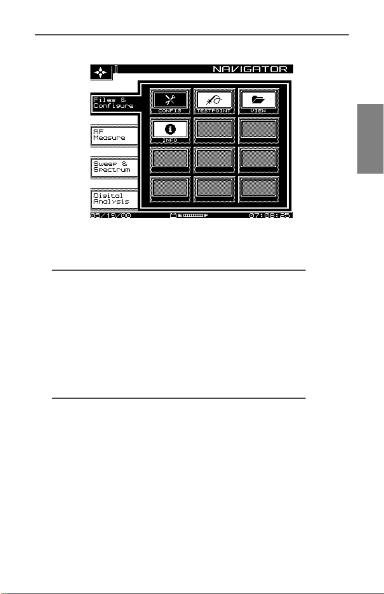
Description and Basic Operation: User Interface El ements
Fig. 2-1 The SDA-5000 Navigator Interface Showing the
Files and Configure Tab
NOTE: If you’re having trouble reading the screen, there
are two adjustments you can make:
• Adjust screen contrast by pressing the Function key
(the green key in th e lower righ t corner of th e unit), then
the 9 yz key to call up the contrast slider. Use the
diamond keys to make the desired adjustment. Then
press the Enter ke y (just above the Function key) to set
the new contrast level.
2
• The LCD screen backlight is activated (or deactivated)
by pressing the Function key twice.
Navigator Tabs and Icons
Page references in the following list point you to the main discussion in the
manual. Note that the icons dis played depend on the uni t’s option s. Y our uni t
might not show all of them.
11
Page 36

Description and Ba sic Operation: User Interface Elements
Files and Configure tab RF Measure tab
Config ..........page 22 Level..............page 110
Testpoint ......page 60 Tilt..................page 112
View.............page 200 Scan..............page 115
Info...............page 32 C/N................page 119
2
Sweep & Spectrum tab Digital Analysis (QAM OPT4)
Sweep..........page 64 Digital............page 153
Spectrum .....page 131 Equalizer.......page 174
PathTrak......page 141 Constallation .page 166
Align.............page 90 Ingress ..........page 160
Modem C/N .page 121
Hum...............page 124
Mod ...............page 126
Auto Test .......page 184
Loopback.......page 93
12
Page 37
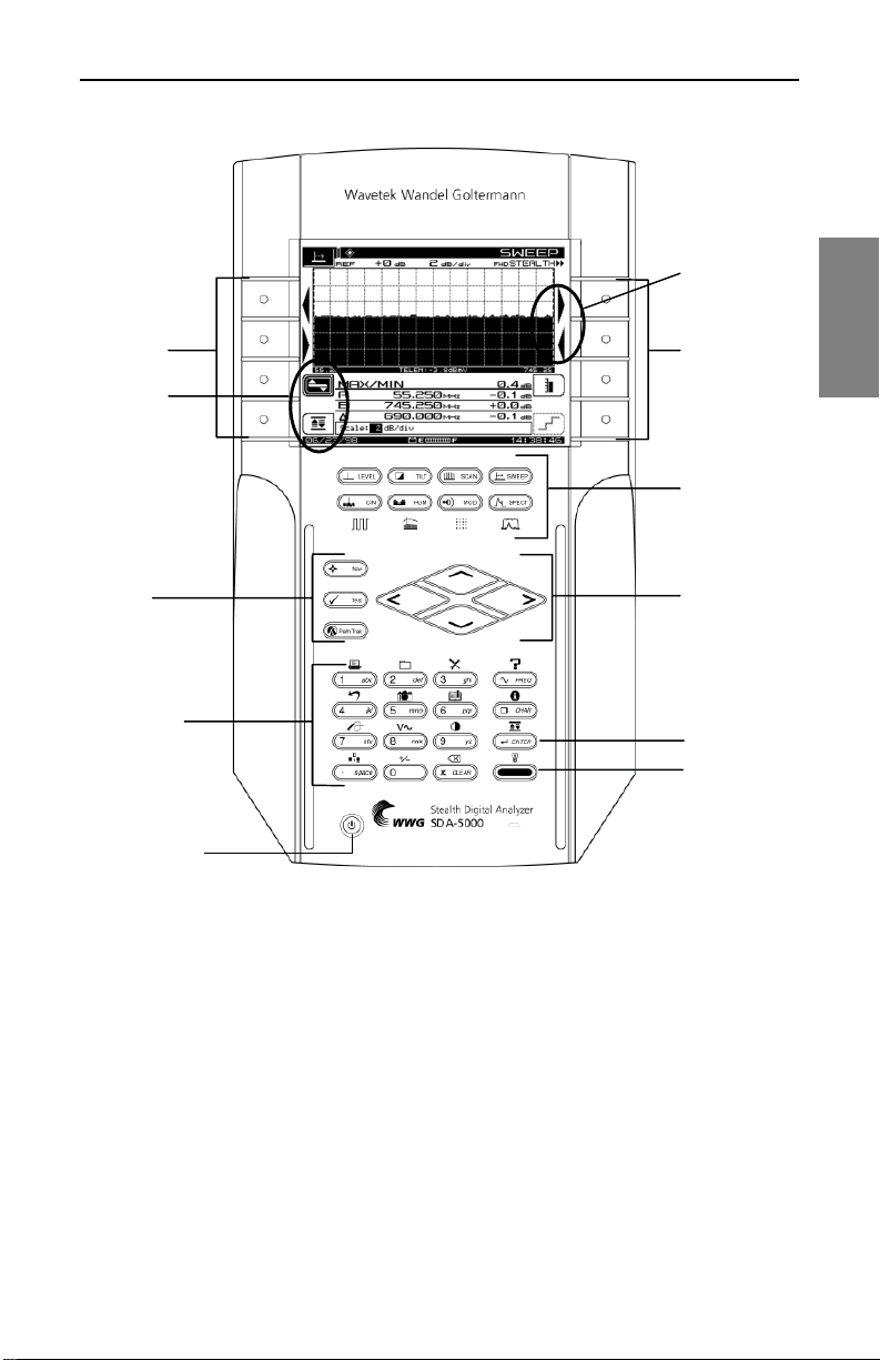
Soft Keys
Soft Icons
Description and Basic Operation: User Interface El ements
Arrows are
displayed for
one-hand
convenience
Soft Keys
Measurement
Mode Keys
2
Suppor t
Keys
Alphanumeric
Keypad
Power On/Off
Fig. 2-2 The SDA-5000 Key Controls
Key Controls
There are five groups of keys that control the SDA field units (see Fig. 2-2):
• Eight soft keys. In many cases, icons that represent soft key functions
are displayed in the LCD next to the soft key.
• Eight measurement mode keys, plus an additional four shifted keys if
you have the QAM op tio n (O P T4) (see Chapter 9, Digit a l An aly sis (QAM
View OPT4), Fig. 9-2).
Diamond
Keys
Enter Key
Function Key
13
Page 38
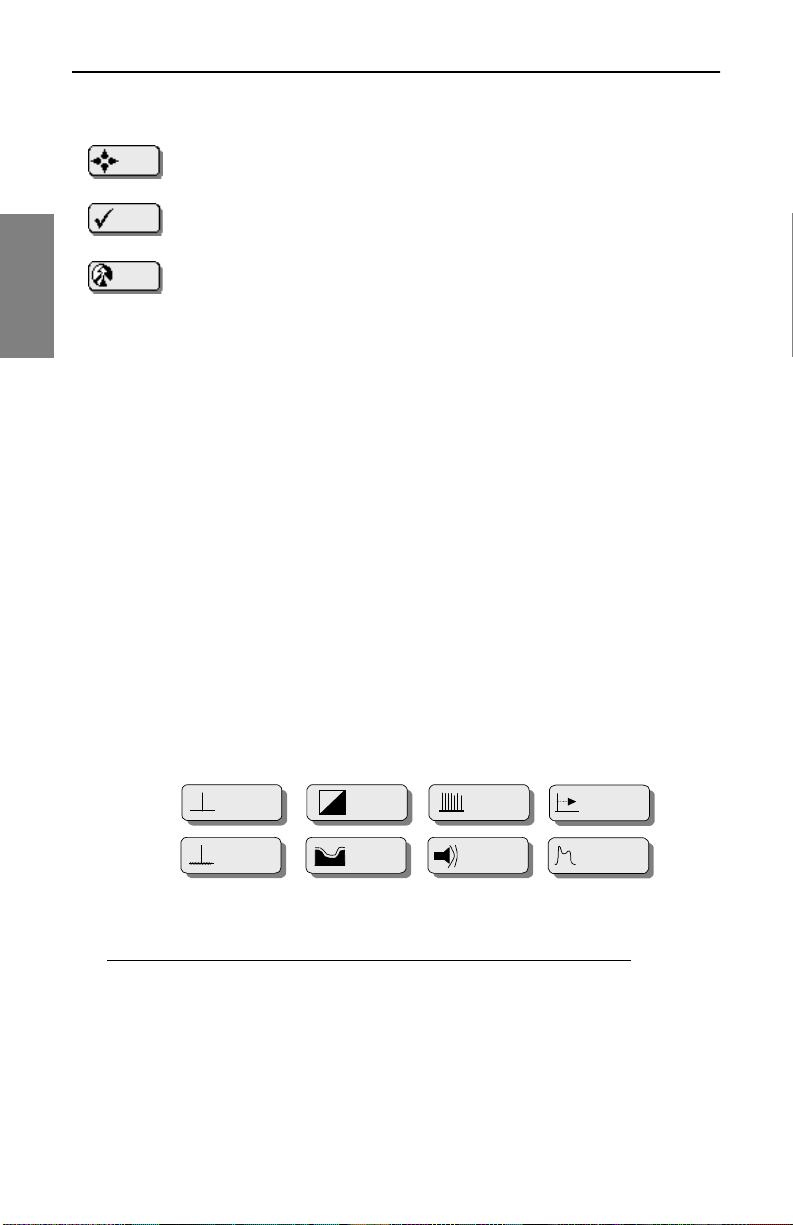
Description and Ba sic Operation: User Interface Elements
• Three support mode keys:
• Nav calls up the Navigator menu.
Nav
Test
• Test accesses the AUTOTEST top-level menu.
• PathTrak enables PathTrak functions. (This requires that your
2
unit has OPT3, PathTrak Field View.)
• Four diamond keys for scrolling menu items, cursors, values, and so on.
• A power button
• A sixteen button alphanumeric keypad.
Soft Keys
Soft keys enable you to access a set of up to eight programmable functions
at a time. The specifi c functions available change as you chang e operation al
modes. For example, changing from the Level mode to the Tilt mode
changes the soft key functions available to you. Icons represent many soft
key functions.
See Also
½ Appendix C has a complete list of these icons.
Measurement Mode Keys
Measurement modes are activated by pressing one of the eight keys (shown
in Fig. 2-3) immediately below the LCD.
14
LEVEL
LEVEL
C/N
C/N
TILT
TILT
HUM
HUM
SCAN
SCAN
MOD
MOD
SWEE P
SWE E P
SPECT
SPECT
Fig. 2-3 The Measurement Mode Keys
NOTE: If you have the QAM option, the bottom four keys
(C/N, HUM, MOD, and SPECT) have shifted func tio ns that
you access by pressing the green Function ke y befo r e
pressing the measurement mode key. Chapter 9, Digital
Page 39

Description and Basic Operation: User Interface El ements
Analysis (QAM View OPT4), has more information about
these keys.
• Press LEVEL to check the audio and video levels of a channel
simultaneously, or to check a specific frequency.
• To balance pilot levels, press TILT. Nine selected video c arrier level s are
displayed.
• Press SCAN to see absolute carrier levels on a bar graph. All carriers
are displayed.
• Press SWEEP to test CATV system frequency response. Low-level
signals are injected into vacant spectrum areas by the SDA-5500, and
system carrier reference levels in occupied spectrum areas are
transmitted via telemetry to the SDA unit.
• Press C/N to measure the carrier-to-noise ratio in dB on the tuned
channel or frequen cy, at a preset noise frequency offset abo ve the video
carrier.
• Press HUM to measure low-frequency hum modulation on the selected
channel. You can select to view the measurement in dB or as a
percentage.
2
• Press MOD to listen to the audio modulation of the tuned channel or
frequency (AM or FM), and measure the depth of modulation on the
video carrier. Depth is presented as a percentage.
• Press SPECT to activate the spect rum analyz er disp lay, and to measure
CSO/CTB harmonic distortions (in conjunction with the designated soft
key).
See Also
½ Chapters 4, Field Sweeping with the SDA-5000, 6,
Measuring System Pe rform ance, and 7, S pectru m Analy zer
Mode, describe these modes in detail.
½ These modes are intr oduced i n “Basic Modes o f Operati on,”
later in this chapter (page 17).
½ Chapter 9, Digital Analysis (QAM View OPT4), covers the
shifted functions of the measurement mode keys.
15
Page 40
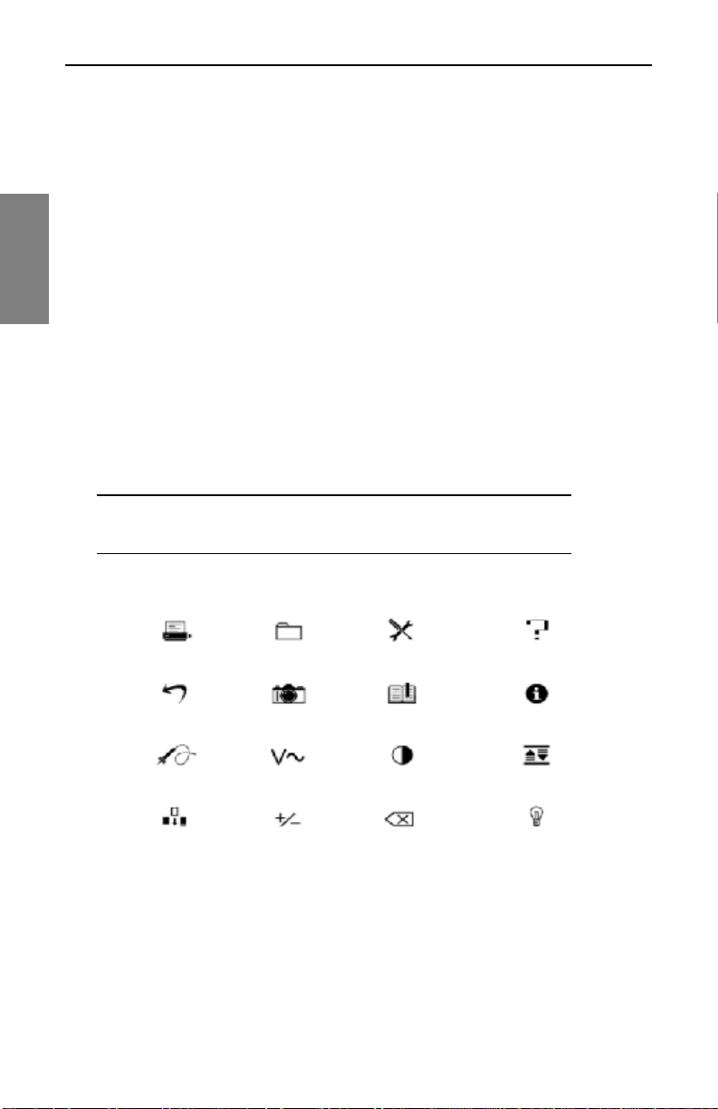
Description and Ba sic Operation: User Interface Elements
Alphanumeric Keypad
The alphanumeric keypad is augmented with green icons above each key
(see Fig. 2-4). The functions represented by these icons are selected or
activated by first pressing the green Function key at the lower right of the
keypad (see Fig. 2-2), then the key for the desired function.
The alphanumeric keys are used to
2
• Enter numeric values 0 through 9. The Function key makes the 0 key
toggle between +/- wh en neg ative entri es are a llowed i n dat a e ntry fields .
• Enter a decimal point using the . sp a ce key.
• Enter letters in Edit Box da t a f iel ds that ac cep t al ph a ch ara cte rs s uch a s
test point names, opera tor names, file nam es, and so on. Press each key
one, two, or three times to choose the letter desired. Pressing a key an
extra time brings up the number assigned to the key.
• Create a space between letters with the arrow keys.
• Move the cursor with the arrow keys.
NOTE: Always finish numeric entries by pressing the
Enter key or the appropriate soft key.
Print File Configure Help
Backup Screen Hold Reference Information
TP Comp DVM Contrast AutoScale
16
Insert Toggle ± Delete Backlight
Fig. 2-4 The Shifted (or Second) Functions of the Keypad
Page 41
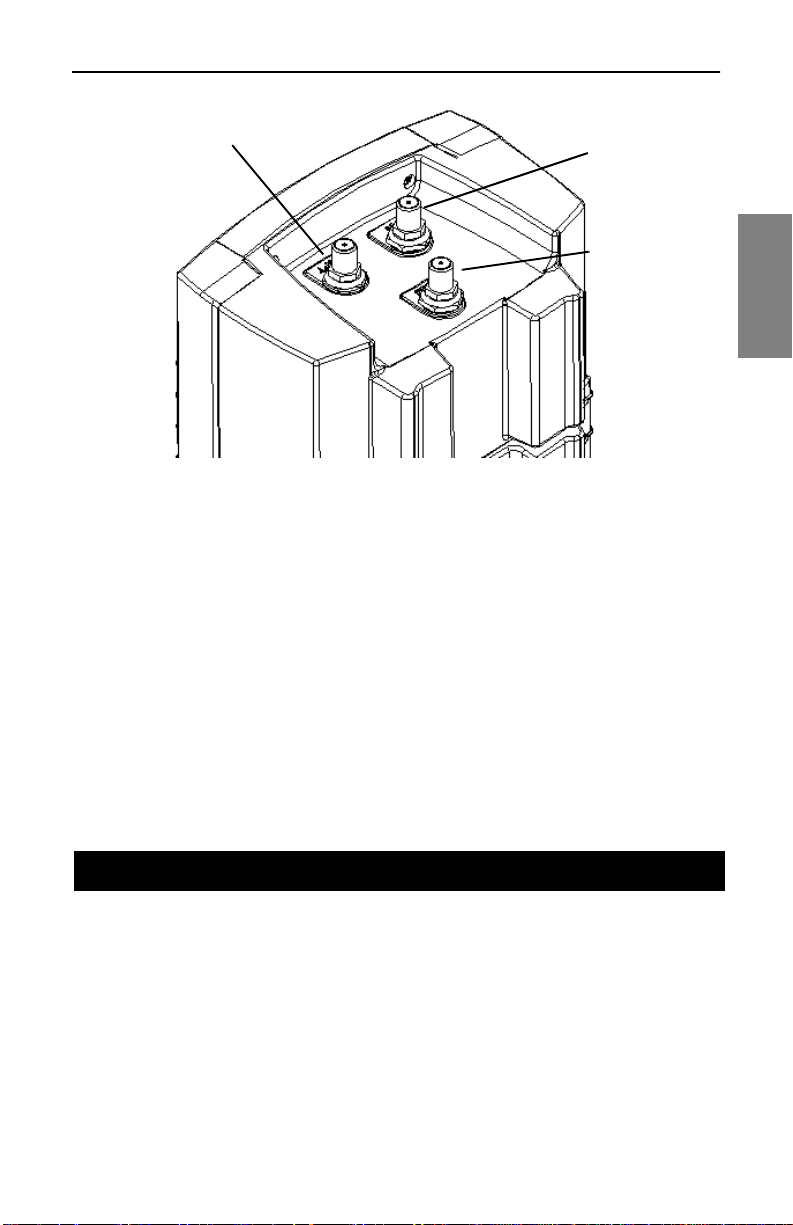
Description and Basic Operation: Basic Modes of Ope ration
OPT port
IN port
DIGI port
Fig. 2-5 Top View of the SDA-5000 Showing the Three
Cable Connection Ports
Cable Connection Ports
SDA units have up to three cable conn ection p orts (s ee Fig. 2-5 ). The IN po rt
allows you to connect the instrument to the cable system. When connected,
you can perform sweep operations, standard analog measurements, and
digital carrier average power measurements. The OPT port is a transmitter
port used when you’re performing reverse sweep, CW Loopback, or Sweep
Loopback measurements. The DIGI port allows you to analyze digital TV
and forward cable modem signals.
2
BASIC MODES OF OPERATION
This section describes the modes of operation for SDA field units. Some
modes require you to have a parti cular option on your SDA unit. Whe n that is
the case, the required option is indicated in parentheses next to the mode
name.
Level Measurement
Your SDA-5000 offers several different level displays optimized for many of
the day-to-day tasks of maintaining your cable system.
17
Page 42
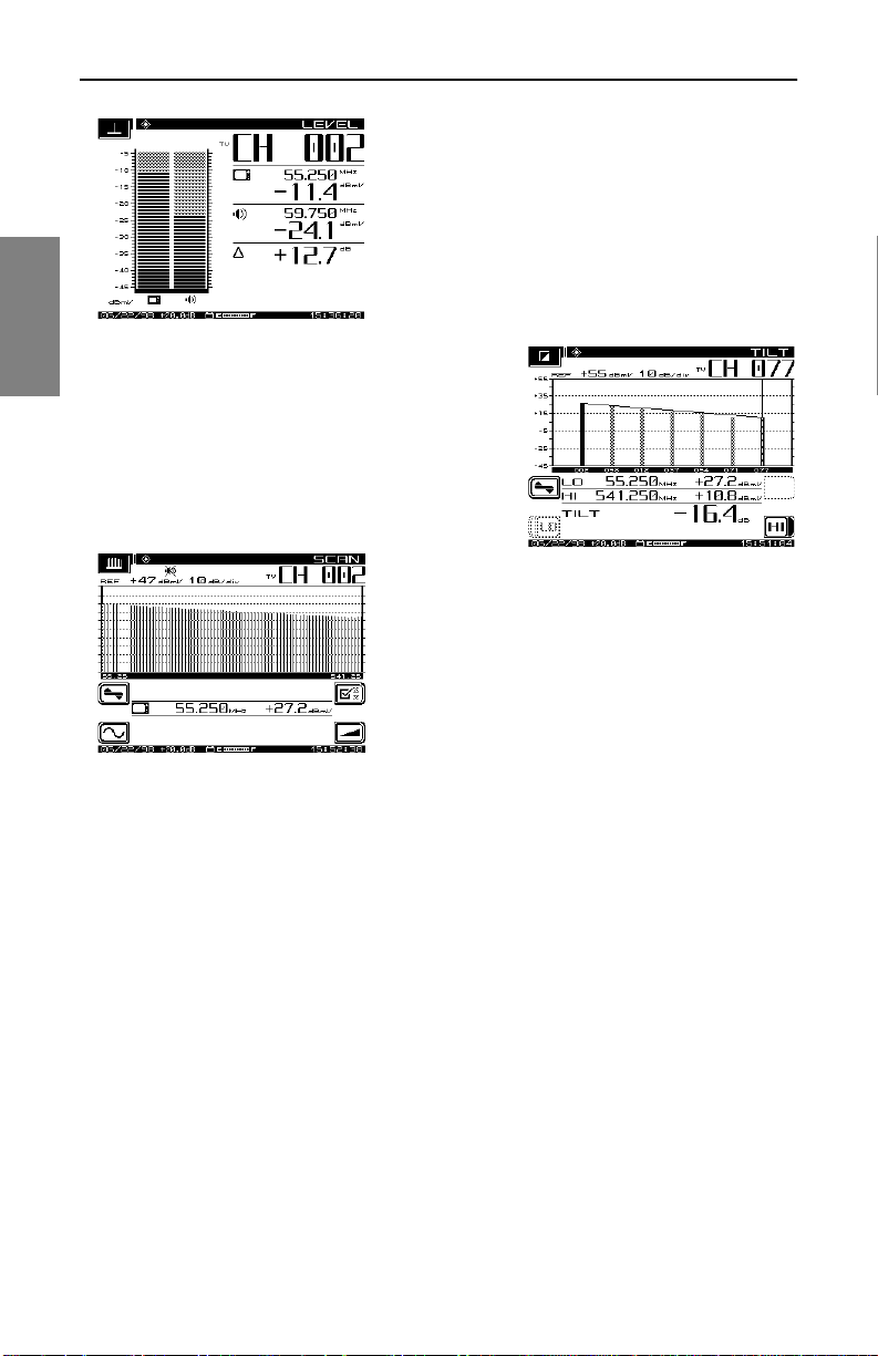
Description and Basic Operation: Basic Modes of Operation
LEVEL mode presents a de tailed dis play about
a single channel. Video and audio levels are
displayed both in bar graph and in numeric
form. The delta between audio and video level
is also computed. When a digital channel is
measured, DigiCheck power measurement
algorithms are used to accurately read
continuous digital carrier levels across the
2
TILT mode displays level variations of
selected carriers throughout the band. Up
to nine selected tilt channels are measured
and displayed at the same time. Thes e can
be the pilot carriers or cha nne ls . Th e m et er
automatically calculates tilt across these
channels and display s thei r leve l.
entire selected channel.
SCAN mode displays a graph of the level of all
channels in the current chann el pla n, eith er
with or without audio and digital carriers. This
mode is very useful when you’re first
connecting to a test point. It allows you to
quickly get a general idea of system specified
signal level accuracy.
See Also
½ Chapter 6, Measuring System Performance, describes
these measurement modes in detail.
Sweep
Sweep is the most comp lete way to measure the freque ncy res ponse of your
cable network. SDA products offers a complete set of sweep tools to
maximize your productivity. Forward and reverse sweep can be used to
troubleshoot problems in either signal path. Reverse amplifier alignment is
designed to quickly provide yo u with the ne cessary inf ormation fo r setting up
a reverse amplifier, and Sweepless Sweep can be used to gather sweep
information even when there is no sweep transmitter available.
• Stealth forward s w eep : Forwa rd s weep uses a headend trans mi tter t o
measure carrier levels and, when necessary, to inject short sweep
pulses. When stable carriers are present, they can be referenced to
18
Page 43

Description and Basic Operation: Basic Modes of Ope ration
create a sweep response without injecting any sweep pulses. This
guarantees that no subscriber interference will result from your sweep
testing.
• SDA sweep: SDA sweep operates id enti ca lly to Stealth sweep, but it is
much faster! It is also critical to note that, for SDA sweep to work, you
must be using SDA equipment both in the headend and in the field.
• Stealth reverse sweep (OPT1): Reverse sweep uses sweep carriers
from a field unit that are sent back to the headend transmitter and
measured to calculate return path frequency response. Stealth offers a
high level of flexibility in setting frequencies and levels to give you the
maximum flexibility in sweeping a return path network without creating
any service interruptions.
• Aligning reverse ampl ifiers (OPT1): T his alig nment mode is t ailored to
set the gain and tilt of reverse amplifier units. Using the SDA-5500 or
SDA-5510 headend sweep transmitter, this screen shows the absolute
signal levels at two selected frequencies and calculates the gain and tilt
of a return path sy stem. All the informatio n a techni cian need s to set up a
reverse amplifier or node is dis played in one location .
• Sweepless Sweep: Sweepless Sweep allows you to get sweep
information even if no trans mitter is av ail abl e. If a tran sm it ter is down, or
if something is blocking the telemetry channel, Sweepless Sweep can
still be used. In Sweepless Sweep, the SDA field unit measures the
stable carrier level s, memorizes them, and establis hes a referenc e.
These levels can then be compared with the levels of the same carriers
at a different point in the network, and the differences in frequency
response can be highlighted.
• Loopback Sweep (OPT2): The full sweep local Loopback test enables
you to perform a rough frequ en cy respon se, gai n, and l oss te st on ac tive
and passive devices in the field using a single meter.
2
See Also
½ Chapters 4, Field Sweeping with the SDA-5000, and 13,
SDA-5500/SDA-5510 Sweep Configuration, together
provide a complete description of the SDA family’s sweep
capability.
Proof-of-Performance Measurement Tools
The SDA-5000 provides an extensive suite of tools for troubleshooting and
for performing proof-of-p erforma nce test s. Carrier-to-no ise, hu m, and de pth
of modulation are all calculated on unscrambled analog video channels in-
19
Page 44
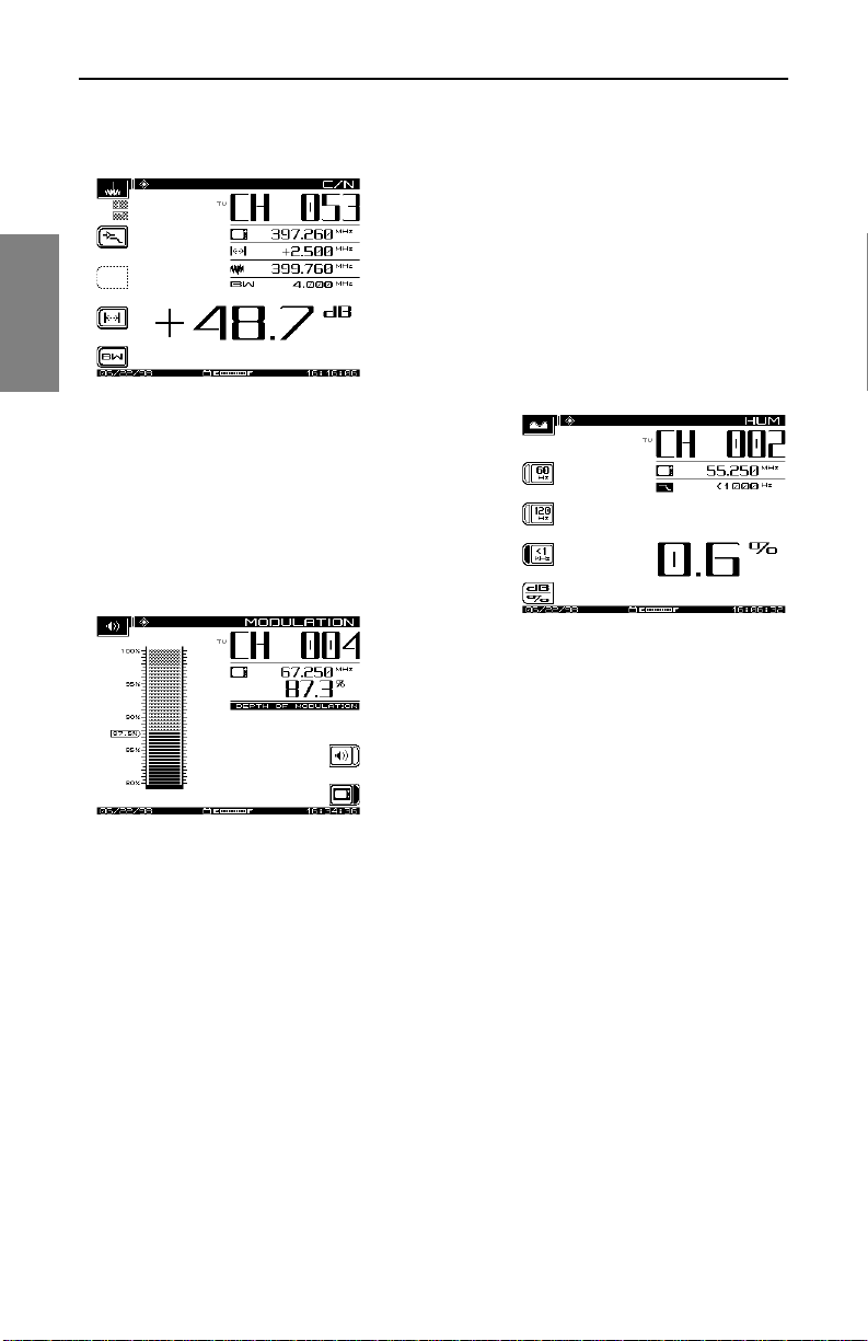
Description and Basic Operation: Basic Modes of Operation
service and in-channel. This allows you to measure the performance
customers really experience, all without any ser vice interruption.
Carrier-to-noise is measured using an
advanced “quiet line” algorithm. The meter
searches for a line of video with no active
signal (this typically happens on one or more
lines during vertical sync of an analog video
2
Hum is also measured in-service using
DSP algorithms. Pre-programmed filters
help isolate power supply problems to 1times power-frequency, 2-times powerfrequency, or all low frequency
components.
channel). This allows the noise measurement
to be made in the middle of the channel rather
than in an unused side band, so the readin g
reflects what the CATV subscriber actually
sees.
Depth of modulation can be measu red inservice. This display also allows the user to
listen to either AM or FM audio carriers to help
identify a signal or to troubleshoot some types
of problems. If a steady ingress source is
found, this feature can be used to help find out
what is leaking into the cable network.
The SDA-5000 also offers the capability to perform these proof-ofperformance tests on an automated basis. You can perform a complete
battery of tests for any or all channels in the channel plan. The meter can
perform these tes t s immediately, or it can perform a set of tes t s ov er any set
of intervals you desire. This is useful when you’re running the 24-hour tests
required by the FCC in the US, and by other international governing bodies.
See Also
½ Chapter 6, Measuring System Performance, discusses the
proof-of-performance measurement tools in detail.
½ Chapter 10, Automatic Test, explains how to run 24-hour
and interval tests.
20
Page 45
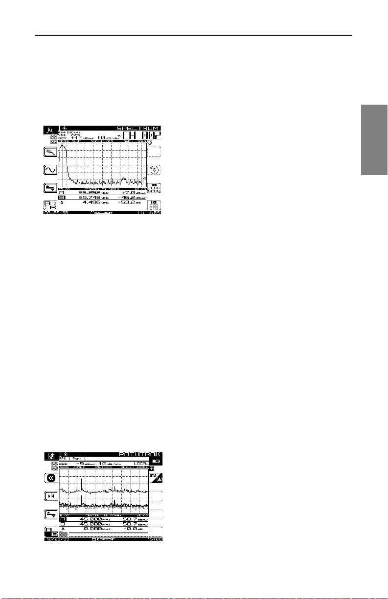
Description and Basic Operation: Basic Modes of Ope ration
Spectrum Analysis
The SDA-5000 features an adva nc ed sp ec trum ana lys is capability. This is a
simple but extensive tool for tracking down hard-to-find problems in the
cable network. The following list describes t he features of this tool:
The spectrum analyzer works over the entire 5
MHz to 1 GHz frequency range.
Tuning can be by channel or by frequency.
Several convenient frequency spans are
available, from 3 to 50 MHz.
Maximum hold and dwell time can be varied to
track down intermittent signals.
A low-pass filter and preamplifier are available
to help find difficult return path problems.
The spectrum mode includes a very powerful Zero Span mode display that
you can use to measure and anal yze TDM A (T i me Divis ion Multip le Acces s)
digital channels and difficult ingress signals. Zero Span mode allows you to
perform in-service and in-channel D/U (desired/undesired) measurements
on TDMA channels. You can also see diffe rent transmi tter levels individua lly,
view data “collisions,” and see how heavy the traffic is on the coax.
2
You can also measure CSO (composite second order) and CTB (composite
triple beat) using Spectrum mode. These measurements can help you find
the source of inter-modulation problems and confirm compliance with
system performance specifications.
See Also
½ Chapter 7, Spectrum Analyzer Mode, covers the spectrum
analysis c apability of the SDA-5000.
PathTrak Mode (OPT3 Field View)
The PathTrak mode di splay looks very similar
to the Spectrum Analyzer display. However, the
PathTrak mode has two measurement traces
(Local and Remote) that are displayed
simultaneously along with a Peak Hold trace.
You can toggle the Peak Hold trace to
reference either the Local or Remote trace.
Simultaneous display of both traces allows you
21
Page 46

Description and Basic Operation: Configuring the SDA-5000
to toggle between the Local and Remote traces to compare measurement
data so you c an quic kly dete rmine if a n ingr ess probl em exist s, and i f it do es,
you can isolate its source.
See Also
½ Chapter 8, PathTrak Field View (OPT3), discusses the
PathTrak Mode in detail.
2
CONFIGURING THE SDA-5000
This section describes the configuration options you access from the
CONFIGURE menu. Global, Measurements, and Diagnostic configuration
are discussed here in detail. Channel Plan, Sweep Receiver, and PathTrak
configuration are covered briefly in this chapter, and in detail in their
respective chapters later in the manual.
To call up the CONFIGURE menu shown in Fig. 2-6, turn the unit on and
then either
• Press the Nav support key (see Fig . 2-2), sel ec t the File s an d C on fig ure
tab, then the crossed-tool Config icon
or
• Press the Function and 3 ghi keys
NOTE: If the internal transmitter requires self-calibration,
you will see a prompt to perform a self-calibration of the
internal transmitter. See page 30 for instructions on how to
do this.
22
Page 47
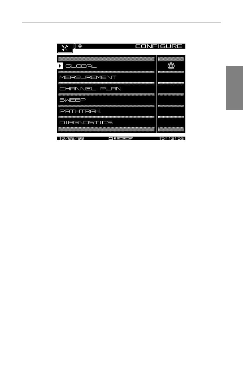
Description and Basi c Operation: Configuring the SDA-5000
Fig. 2-6 The CONFIGURE Menu
Global Configuration
Selecting the GLOBAL option calls up the menu shown in Fig. 2-7. This
menu contains twelve items, described in the list that follows.
2
• Operator Name: Enter your name, which will appear in the header
section of the Auto Test report (see “Auto Test Results” in Chapter 10,
Automatic Test).
• Contrast Level: Adjust the contrast level of the LCD to the desired
level. The l evel varies on a scale from 1 to 15.
• Shut-off Time-out Period: To conserve battery life, you can adjust the
automatic shut-off feature to turn off the meter after a pre-set interval of
inactivity of 1, 3, or 5 minutes, or choose Always On.
23
Page 48
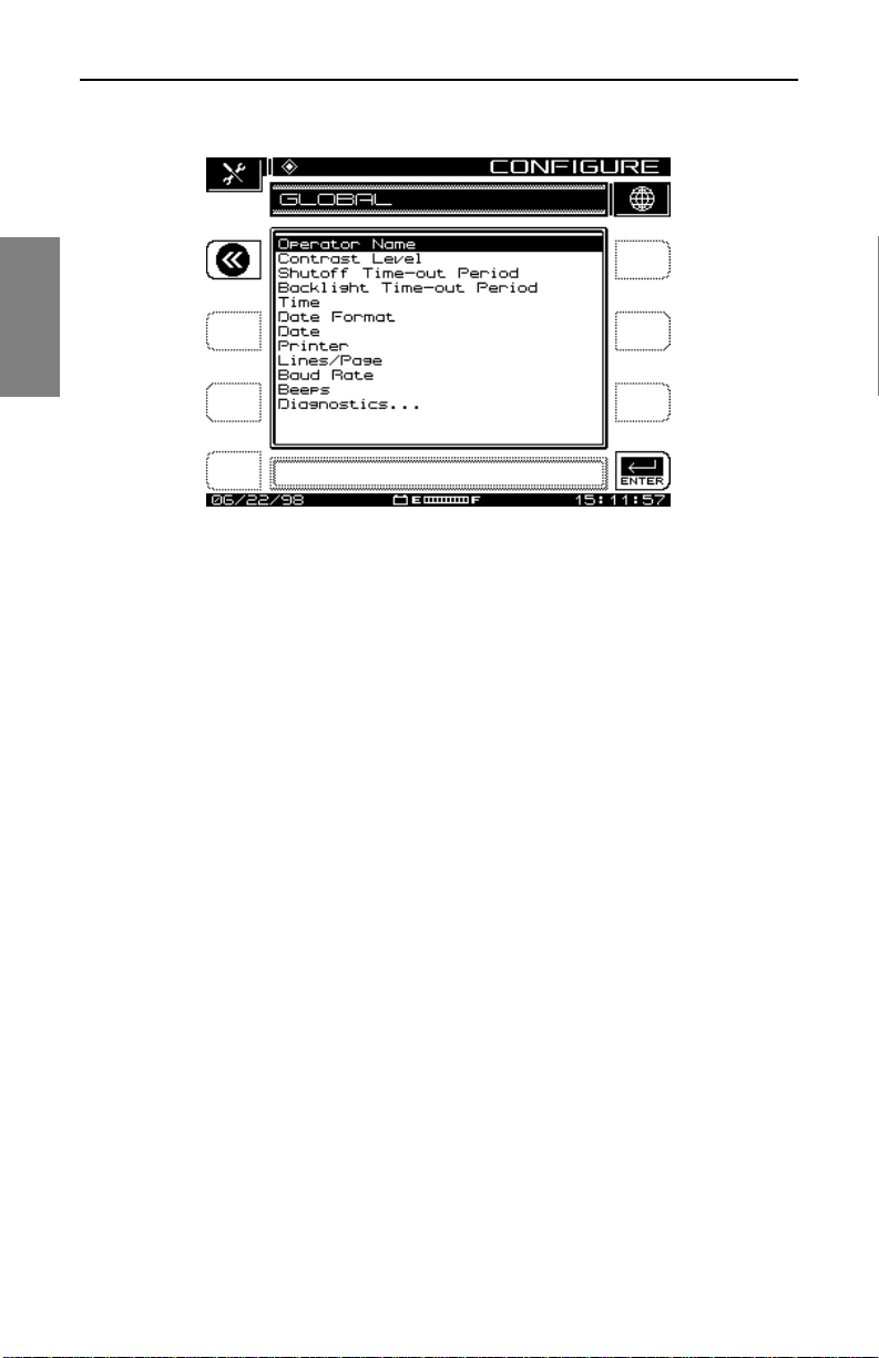
Description and Basic Operation: Configuring the SDA-5000
2
Fig. 2-7 The GLOBAL Menu
• Backlight Time-out Period: You can also conserve battery life using
the screen backlight’s automatic time-out. The time-out period is
programmable: Always Off, 5 sec, 10 sec, or Always On. (You can turn
the backlight on or of f manually at any tim e by pressing the Function key
twice.)
• Time: Use the numeric entry keys to enter the time in HH:MM:SS
format. The time is set using a 24 hour scheme (for example, 18:05:30
for 6:05 and 30 seconds PM).
• Date Format: Use the up and down diamond keys to select the date
format. When you change the date format, the new format will appear
everywhere the date is displayed or printed. The following formats are
available:
MM/DD/YY
DD.MM.YY
YY.MM.DD
• Date: Use the numeric entry keys to e nter the date. Select Dat e Format,
Next . . . to determine which date display format is used.
• Printer: Sets the printer interface. Use the up and down diamond keys
to choose between Diconix, Seiko, IBM, or Epson.
24
Page 49

Description and Basi c Operation: Configuring the SDA-5000
The required serial printer configuration is as follows:
• Baud rate consistent with SDA-5000 Receiver (9600 or 19.2K
recommended)
• 8 data bits
• 1 stop bit
• No parity
• Flow control - hardware handshaking
Printing to a par allel printer re quires a serial-to-p aralle l converter s uch as
the one manufactured by Black Box Corp. (Phone 412-746-5500). The
setup is the same as the serial printer configuration.
• Lines/Page: Use this option to specify the number of lines per page
(min 30, max 255) for text printouts . T his de term in es the nu mb er o f li nes
printed before a form feed command is sent. For no form feeds, enter
zero (0) here.
• Baud Rate: The baud or bit rate establishes the speed of
communications between the SDA-5000 receiver and another device.
Baud values available are 1200, 2400, 4800, 9600, and 19.2k.
• Beeps: Use the diamond keys to turn on or off key-press clicks and
instrument beep functions.
2
• Splash Screen: Use this option to enable or disable the splash screen
that appears when you turn on the unit.
• Diagnostics: To enter Diagnostics mode, hi ghlight th is option and press
the Enter key.
See Also
½ The “Diagnostics” section later in this chapter covers
diagnostics configuration in detail (page 29).
Measurements Configuration (Including QAM OPT4)
When you select MEASUREMENT from the CONFIGURE menu shown in
Fig. 2-6, you’ll see options for adjusting seven variables. If you have the
QAM option (OPT4), you will see an additional four items, as described
below (see Figure 2.8). Use the up and down arrow keys to scroll through
the list, and change the variables as indicated in the Edit Box.
25
Page 50
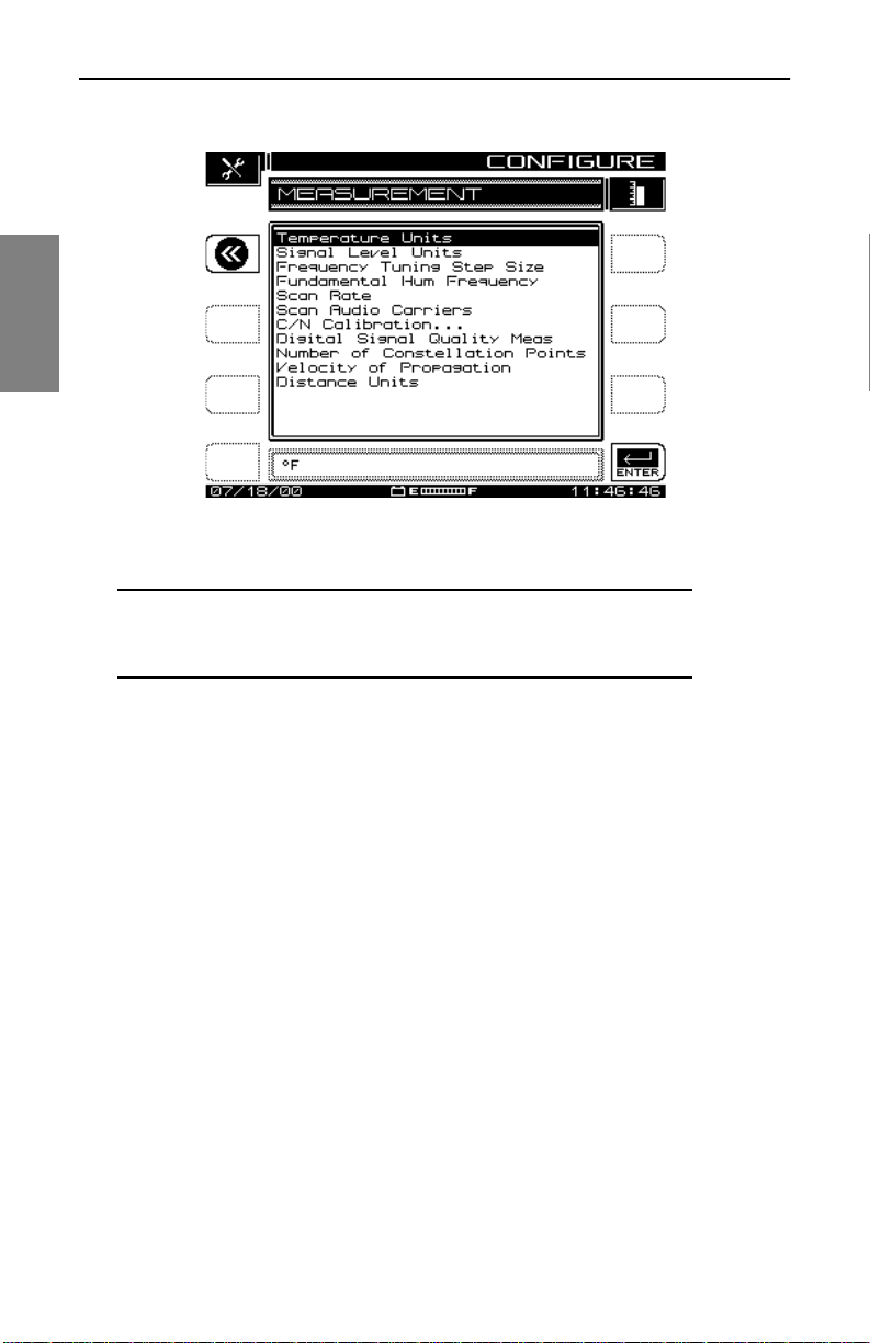
Description and Basic Operation: Configuring the SDA-5000
2
Fig. 2-8 The MEASUREMENT Menu
NOTE: The Test Point Compensation item has been
moved to another menu, TESTPOINT, accessible from the
Navigator or by pressing the Function and 7 stu keys.
• Temperature Units: Select the desired temperature units (degrees
Celsius or degrees Fahrenheit).
• Signal Level Units: Select the units to be used for checking signal
power levels (dBmV, dBuV, and dBm).
• Frequency T uning S tep Size: Adjust the T uning S t ep Size using th e up
and down diamond keys or the numeric entry keys (0.01 to 100.00 MHz
in 10 kHz steps).
• Fundamental Hum Frequen cy: Select the fundament al hum frequency
to be measured (60 Hz, 50 Hz, 1Hz, or, Auto). With Auto selected, the
unit will automatically switch to 50 Hz on PAL type plans and 60 Hz for
NTSC plans. 1Hz is used in the case of a 1Hz power supply.
• Scan Rate: Two scan rates are av ailable in the Scan mode, Normal and
Fast. The Fast scan feature allows for rapid scan displays, but sacrifices
accuracy. The Normal scan rate is slower but more accurate.
• Scan Audio Carriers: Omitting the audio carriers during the scan
produces a f aster scan.
• C/N Calibration: To obtain a valid carrier-to-noise measurement, the
measurement algorithm incorporates a noise floor calibrati on. To perform
26
Page 51

Description and Basi c Operation: Configuring the SDA-5000
the calibration, select C/N calibration and press the Enter key. To get a
valid measurement, t he pr ogra m prompts you to be su re tha t no cab le i s
connected to the RF IN connector. After the measurement is verified,
press the OK soft key to perform the calibration. When the calibration is
complete, the screen displays the noise floor, expressed in the currently
selected units (e.g. dBmV).
Digital Analysis (QAM OPT4) Options
• Digital Signal Quality Meas: This option enables you to select the
digital signal quality measurement you want to use:
• MER (modulation error ratio ) is analo gous to a n analog c arrier-to-no ise
measurement
• EVM (error vector magnitude) is MER data presented in a percentage
format.
• Number of Constellation Points: You can set the number of
constellation points displayed in Constellation mode to 2000, 4000, or
8000. The unit defaults to 4000.
• Velocity of Propagation: The velocity of propagation is the ratio of the
speed at which light travels down a length of cable compared to its
absolute speed. It is determined by the dielectric material used to
separate the two conductors and is usually specified by the cable
manufacturer. After you have consulted the manufacturer’s
specifications, enter a value between 0.00 and 1.00.
• Distance Units: In Equalizer Mode, this option enables you to set the
units for measurin g the di stance to the fault in either feet or met ers . This
option defaults to feet.
Channel Plan Configuration
2
Selecting the CHANNEL PLAN option from the CONFIGURE menu takes
you to a screen where you can set nine channel plan configuration options.
These options allow you to
• Select a channel plan
• Set the video signal type
• Set the channel tuning sequence
• Build a channel plan
• Edit a channel plan
27
Page 52

Description and Basic Operation: Configuring the SDA-5000
• Delete unused channels
• Build sweep points
• Specify Auto Test measurements
• Edit Limits
• Edit Digital Limits
2
• Remotely copy a plan from another instrument
See Also
½ Chapter 3, Channel Plans, covers these options in detail.
Sweep Configuration
The SWEEP option of the CONFIGURE main menu e nables you to esta blish
the operating parameters that you want for a specific sweeping application.
The first screen in this menu offers the options and choices available in
either the Stealth, Stealth (SDA COMPATIBLE), Transmit, Transmit (SDA
COMPATIBLE), Loopback, or Sweepless modes of sweeping. Stealth mode
sweeping is the default setup. The number of options available to you
changes depending on which sweep mode you select.
See Also
½ Chapter 4, Field Sweeping with the SDA-5000, covers
sweep configuration and operation in detail.
PathTrak Configuration (OPT3)
From the P ATHTRAK option of the CONFIGURE main menu you ca n set the
parameters that allow communication between Acterna’s PathTrak
performance monitoring system and the SDA field unit.
The PathTrak mode provides increased troubleshooting accuracy by
allowing you to compare spectrum measurements at the node with the
current conditions at the headend.
Options available to you from the PATHTRAK main menu enable you to set
the Telemetry Frequency used to tr ans mi t data, and to view the lis t of n ode s
currently available from the PathTrak system.
28
Page 53
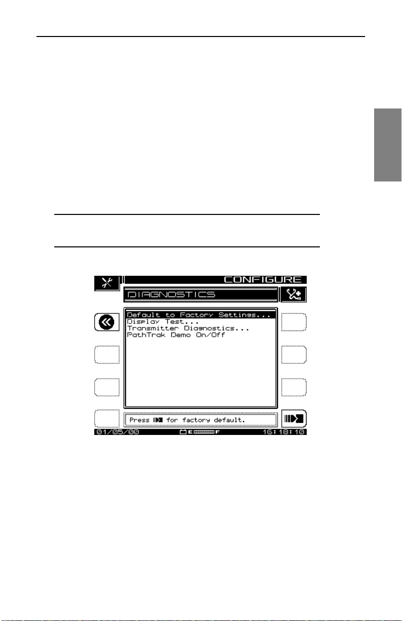
Description and Basi c Operation: Configuring the SDA-5000
See Also
½ Chapter 8, PathTrak Field View (OPT3), covers PathTrak
configuration and operation in detail.
Diagnostics
From the DIAGNOSTICS menu shown in Fig. 2-9, you can reset the
instrument to original factory configuration, test the LCD, or, when
applicable, check the field unit’s inte rnal transmitter functions.
• Default to Factory Settings: Scroll to Default to Factory Settings and
press the Enter key to automatically set all parameters to the factory
default values. The changes will take effect a fter power is cycled.
CAUTION ! Executing this function will cause all saved
files, configurations, and memory to be lost.
2
Fig. 2-9 The DIAGNOSTICS Menu
• Display Test: This option allows you to test the ope ration o f the dis play.
Select Display Test and press the Enter key to call up the scre en s how n
in Fig. 2-10. This test merely checks the on/off properties of the screen.
You have two options, which operate as follows:
• Any left soft key toggles the screen on and off.
• Any right soft key moves to the previous screen.
29
Page 54
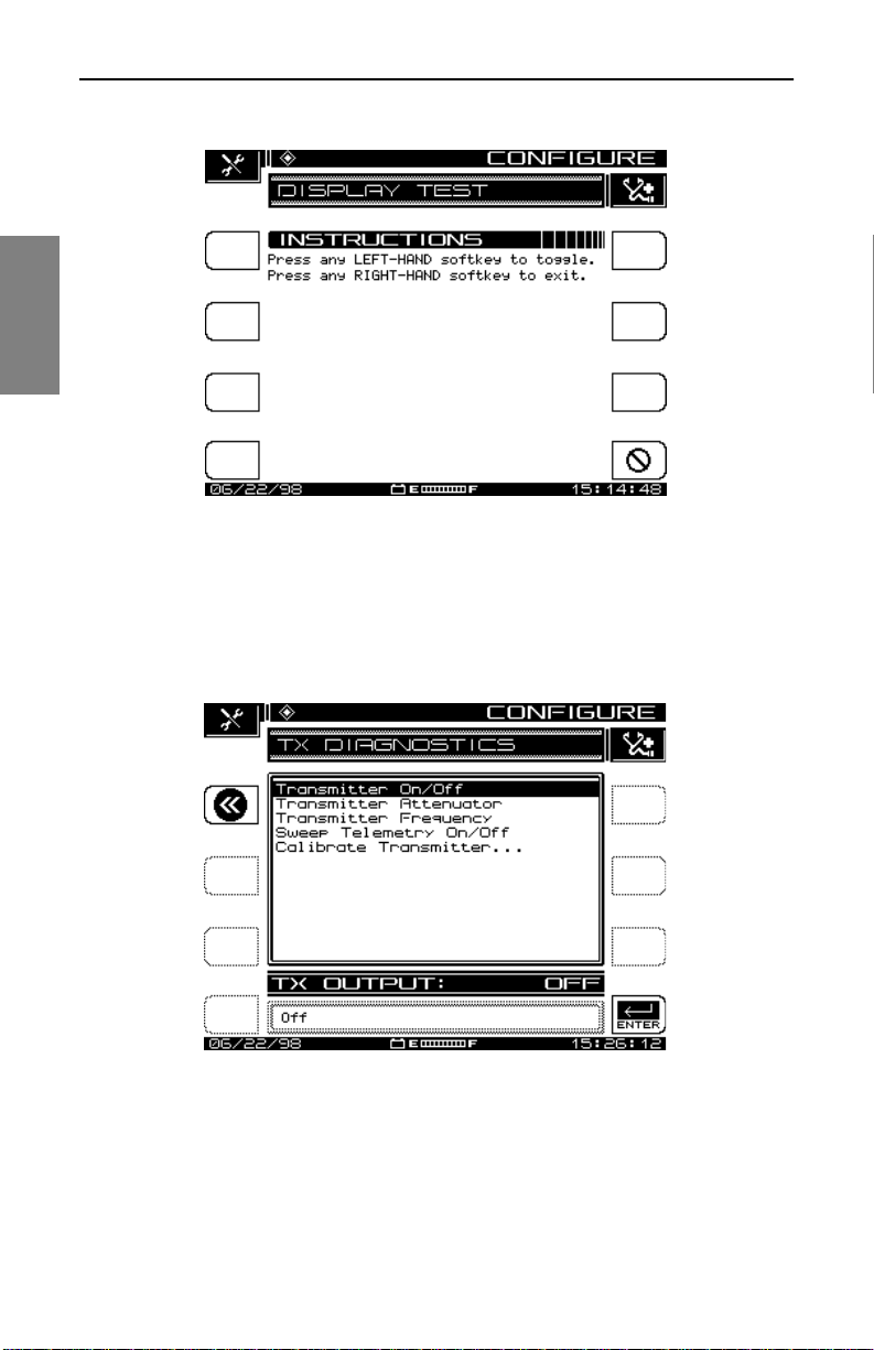
Description and Basic Operation: Configuring the SDA-5000
2
Fig. 2-10 The DISPLAY TEST Screen
• Tr ansmitter Diagnostic s: H ighlig ht this optio n and press the Enter key
to access the internal transmitter diagnostic features shown in Fig.
2-11.
Fig. 2-11 The Transmitter Diagnostics Screen
• Trans mitte r On/Off: When turned on, this feature provides a CW RF
signal that can be used for troubleshooting or during installation. The
signal is pr esent only when the diagnostics screen is displayed.
30
Page 55
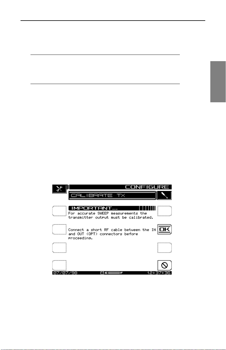
Description and Basi c Operation: Configuring the SDA-5000
• Trans mitte r Attenuator: Use the up and down diamond keys to enter
the amount of attenuatio n for the CW transmit ted signal to a maximum of
30 dB in 2.0 dB increments.
CAUTION ! If you set the transmitter test frequencies too
close to the CATV carrier while you’re connected to the
CA TV system, yo u can create sig nificant inte rference to the
subscribers.
• Tr ans mitter Frequ enc y: Enter the frequency for the transmitted signal
to the nearest 0.01 MHz using the numerical keys and the Enter key.
The up and down diamond keys change the frequency in the increments
established duri ng se tup.
• Sweep Te lemetry On/Off: When it’s turned on, the SDA-5000 will
modulate the CW signal as it does the telemetry signal.
• Calibrate Transmitter: To calibrate transmitter output, press the Enter
key. You’ll see the screen shown in Fig. 2-12. You will be asked to shunt
or jumper with coax the input (IN) and output (OPT) terminals of the
meter with a short length of cable. When you’re done, press the OK soft
key.
2
Fig. 2-12 Calibrating Transmitter Output
If you test without a cable attached, the error shown in Fig. 2-13 occurs.
Check your F connectors, BNC connectors (if used), and the cable itself.
31
Page 56
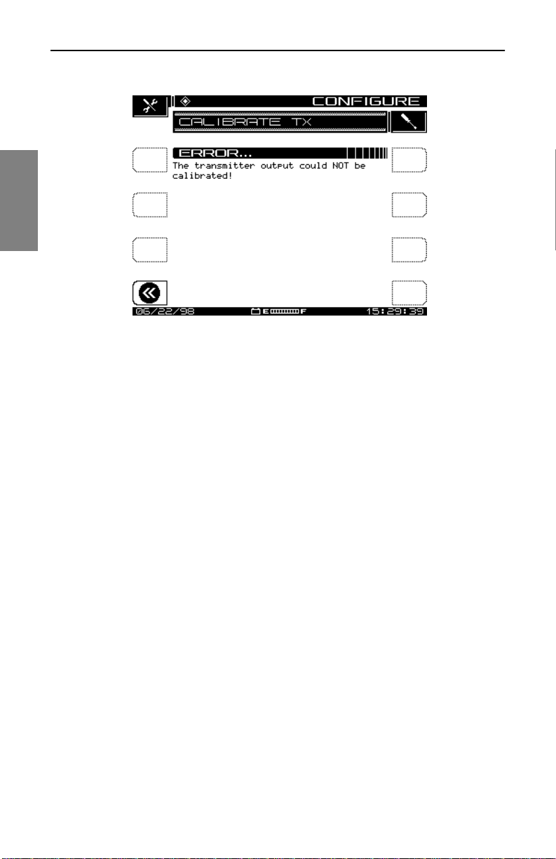
Description and Basic Operation: Configuring the SDA-5000
2
Fig. 2-13 Calibrate Error (Missing Jumper Cable)
If your connections are correct and you still get the error screen, contact an
authorized Acterna Service Center.
See Also
½ Chapter 12, Maintenance, has a list of Acterna service
centers worldwide.
System Information
You can view the system information for your unit by selecting the Info icon
from the Navigator’s Files and Configure tab. Doing so takes you to the
INFO screen where you’ll find the following information:
• model number
• serial number
• firmware version number
• most recent calibration date
• currently selected channel plan Type (NCTA, PAL, SECAM)
• current temperature
• percentage of memory used
• the options the unit has
32
Page 57

Description and Basic Operation: Printing Measurements and Files
PRINTING MEASUREMENTS AND FILES
This section describes the procedures for printing screens or files from your
field unit. Before printing, be sure the printer is properly attached.
NOTE: Interface the SDA-5000 to a PC with an SDA-toPC cable, P/N 1217-50-0158. The SDA-to-SDA interface
cable is P/N 1217-50-0149. The SDA-to-Printer interface
cable is P/N 1217-50-0159. These three cables are
different. Pin-outs and connector types are available by
calling Acterna Customer Service at the appropriate
number for your location as listed in Chapter 12
(page 209).
• To print any measurement mode screen, press the Function and Print
(1 abc) keys.
• To print a file, press the Nav support mod e key an d use the arrow key s to
select View mode. Use the soft keys or press the Function and Print
(1 abc) keys.
See Also
2
½ The “Global Configuration” section earlier in this chapter
discusses setting up your unit for printing to a serial or
parallel printer (page 23).
33
Page 58

Description and Bas ic Operation: Printing Measurements an d Files
2
34
Page 59

Chapter 3
Channel Plans
INTRODUCTION
Using a channel plan, the SDA field unit mem orizes the frequen cies of active
channels on your system.
NOTE: Separate channel plans are required for:
• general measurements (tilt, level, and so on)
• reverse sweep
• loopback sweep
Changing the channel plan on the field u nit has no ef fect on
the sweep. The headend unit’s channel plan is used by
default.
Before you begin, be sure that:
• You have completed the basic setup as described in:
• “Global Configuration” (Chapter 2, page 23)
• “Measurements Configuration” (Chapter 2, page 25)
• “Sweep Configuration” (Chapter 4, page 64)
• You are thoroughly familiar with the inst rum ent’s functions, controls, and
indicators.
Page 60

Channel Plans: Channel Plan Configuration
CHANNEL PLAN CONFIGURATION
To begin, turn the power on and go to the CONFIGURE menu, either by
pressing the Nav key, selecting the Files & Configure tab, and then the
Config icon, or by pressing the green Function key and then 3 ghi.
Depending on yo ur un it’s options, the CONFIGURE menu includes up to si x
items (see Fig. 3-1). Use th e ar row ke ys to s ele ct the C HA NN EL PL AN ite m
and then press any soft key.
The screen displays the top-level CHANNEL PLAN menu shown in Fig.
3-2.
3
NOTE: If you have the QAM option, the CHANNEL PLAN
menu will have an Edit Digital Limits option in addition to
those shown in Fig. 3-2.
From this menu you can access submenus that will let you accomplish the
following tasks:
• Select a channel plan
• Set the video signal type
• Set the channel tuning sequence
• Build the channel plan
• Edit the ch annel plan
• Delete unused channels
• Build sweep points
• Specify Auto Test measurements
• Edit limits
• Edit Digital Limits
• Copy a remote plan from another instrument
The remainder of this chapter will take you through the procedures to
configure each of these functions.
36
Page 61
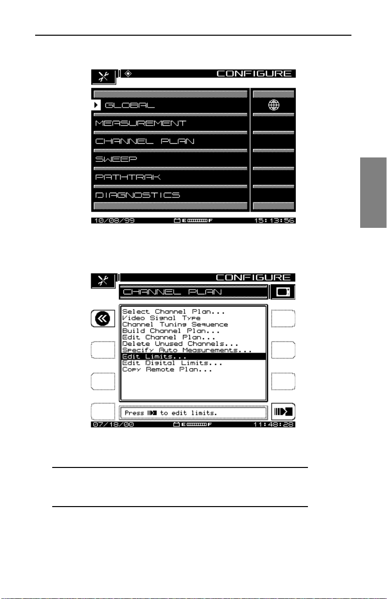
Channel Plans: Channel Plan Configuration
Fig. 3-1 The CONFIGURE Menu
3
Fig. 3-2 The CHANNEL PLAN Menu Options
NOTE: If your SDA instrument does not have the QAM
option (OPT4), you will not see the Ed it Digital Limits. This
menu item applies only to QAM signals.
37
Page 62
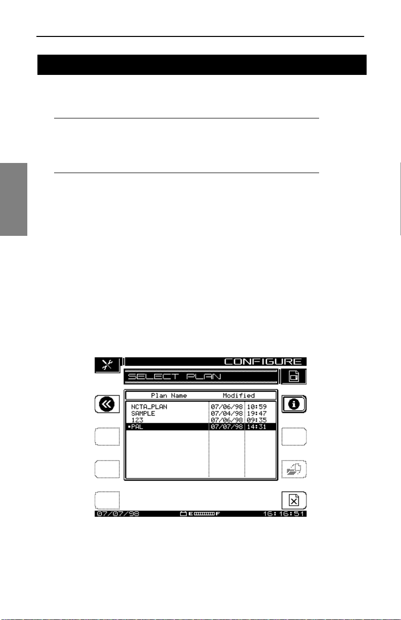
Channel Plans: Setting Channel Plan Parameters
SETTING CHANNEL PLAN PARAMETERS
To set the channel plan parameters, follow the prompts in the Edit Box and
the directions in the following sections.
NOTE: The Return soft key in the upper left moves the
menu back one screen. Press the soft key next to the Edit
Box at the lower right to enter each Channel Plan
submenu.
Select Channel Plan
3
Selecting the top item, Select Channel Plan, takes you to the screen shown
in Fig. 3-3. This is a list of existing channel plans. If this is the first time
you’ve used your SDA field unit , the only c hannel pl an shown is the sta ndard
NCTA plan.
See Also
½ The “Build Channel Plan” secti on later in th is chapte r shows
you how to create and name new channel plans, and add
them to the list displayed here (page 40).
38
Fig. 3-3 Select a Channel Plan
Page 63
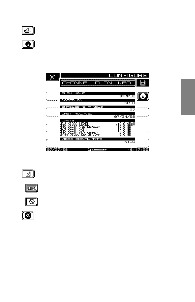
Channel Plans: Setting Channel Plan Parameters
1. Scroll through the list to the plan you want to view, then
press the Load soft key.
2. Press the Info soft key at the upper right of the display to
view the CHANNEL PLAN INFO screen (see Fig. 3-4). Th is
is a view-only screen, which displays main features of the
plan specified in the top line.
3
Fig. 3-4 Channel Plan Info
3. Press the D elete soft key to delete a plan.
To confirm that you do want to delete the selected plan,
press the OK soft key.
If you change your mind before you hit OK, you can press
the STOP key to prevent the deletion.
4. Press the Return soft key to return to the screen shown in
Fig. 3-2, the CHANNEL PLAN menu.
Video Signal Type
From the CHANNEL PLAN menu (Fig. 3.2), select Video Signal Type and
press the Enter key. The up and down diamond keys toggle betw een NTSC,
P A L, and SECAM in the Edit Box.
Select the signal type compatible with your system, and press the Enter key
again. The screen returns to the CHANNEL PLAN menu.
39
Page 64

Channel Plans: Setting Channel Plan Parameters
See Also
½ For more information about these signal types, see the
Glossary at the end of this manual.
Channel Tuning Sequence
At the CHANNEL PLAN menu (Fig. 3.2), select Channel Tuning Sequence
and press the Enter key. The up and down diamond keys toggle between
Numeric Order and Frequen cy Order.
Select the item desired, press the Enter key again, then use the up or down
diamond keys to scroll to the next parameter.
3
Build Channel Plan
From the CHANNEL PLAN menu, select Build Channel Plan. The SDA unit
creates a channel plan by memorizing the active channels in the system,
and by identifying by default those that are not active.
CAUTION ! Be sure that the SDA is co rrectly connecte d to
the cable system at COAX IN.
40
NOTE: Channels < -10 dBmV will not be recognized as
active channels.
1. As prompted by the Edit Box, press the Continue soft key,
and the screen shown in Fig. 3-5, BUILD PLAN STEP 1,
appears.
Page 65
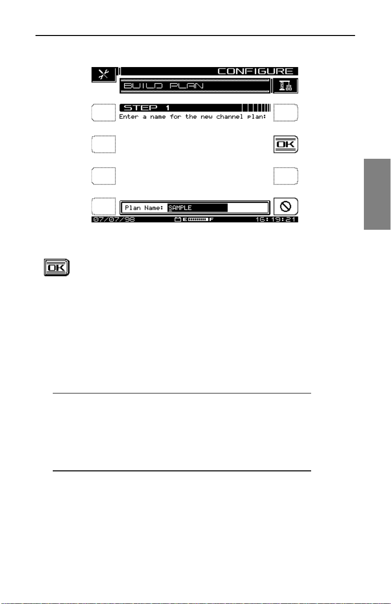
Channel Plans: Setting Channel Plan Parameters
Fig. 3-5 The BUILD PLAN STEP 1 Screen
2. The screen prompts you to name the plan. Use the
alphanumeric keys and the diamond keys to make your
entry, then press the OK soft key to accept it. The screen
warns you if there is already a plan with that name entered
in the unit. After you enter a name for the plan, the BUILD
PLAN STEP 2 screen appears (see Fig. 3-6).
3
See Also
½ For help using the alphanumeric keypad for text entry, see
the section “Alphanumeric Keypad” in Chapter 2 (page 16).
NOTE: If you make a mistake or change your mind about
the name you entered, you can press the OK soft key
again to overwrite it.
Pressing the Stop soft key before you press OK discards
any entry you made in the edit box and returns you to the
STEP 1 screen.
41
Page 66
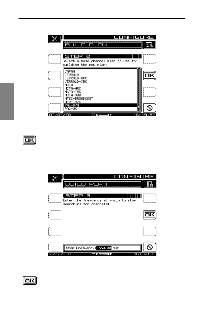
Channel Plans: Setting Channel Plan Parameters
3
Fig. 3-6 The BUILD PLAN STEP 2 Screen
3. At the STEP 2 screen, use the up and down diamond keys
to select a base channel plan to use for building the new
plan. Press the OK soft key to accept you r selection. The
screen shown in Fig. 3-7, BUILD PLAN STEP 3, is
displayed.
42
Fig. 3-7 The BUILD PLAN STEP 3 Screen
4. At the STEP 3 sc reen, ent er the upper freq uency at which to
stop searching for channels. Use the keypad or the up and
Page 67

Channel Plans: Setting Channel Plan Parameters
down diamond keys to set the frequency, press the Enter
key , then press the OK soft key. As the plan starts, you’ll see
the basic plan information and the channels being
programmed into the plan.
CAUTION ! You must press the Enter key to register this
frequency as the upper limit.
When it’s building the channel plan, the SDA sequences through all
channels in the selected base plan up to the St op Freq uen cy you entered.
To halt the process, press t he Stop soft key.
When the channel plan is complete, the screen displays the name and
format for the plan, and the number of enabled channels. The display also
confirms that the first and last enabled channels are tilt enabled.
NOTE: The following section discusses the Tilt Channel
option.
Press the OK soft key and you’re returned to the main CHANNEL PLAN
screen shown in Fig. 3-2.
Edit Channel Plan
This feature enables you to scroll through the entire list of channels in the
plan, select each channel, and edit parameters for each. You can also add
and delete channels from your plan.
1. From the main CHAN NEL PLAN m enu, se lect Edit Chann el
Plan and press the icon to the right of the Edit Box. The
EDIT CHANNEL PLAN screen appears (see Fig. 3-8).
3
43
Page 68
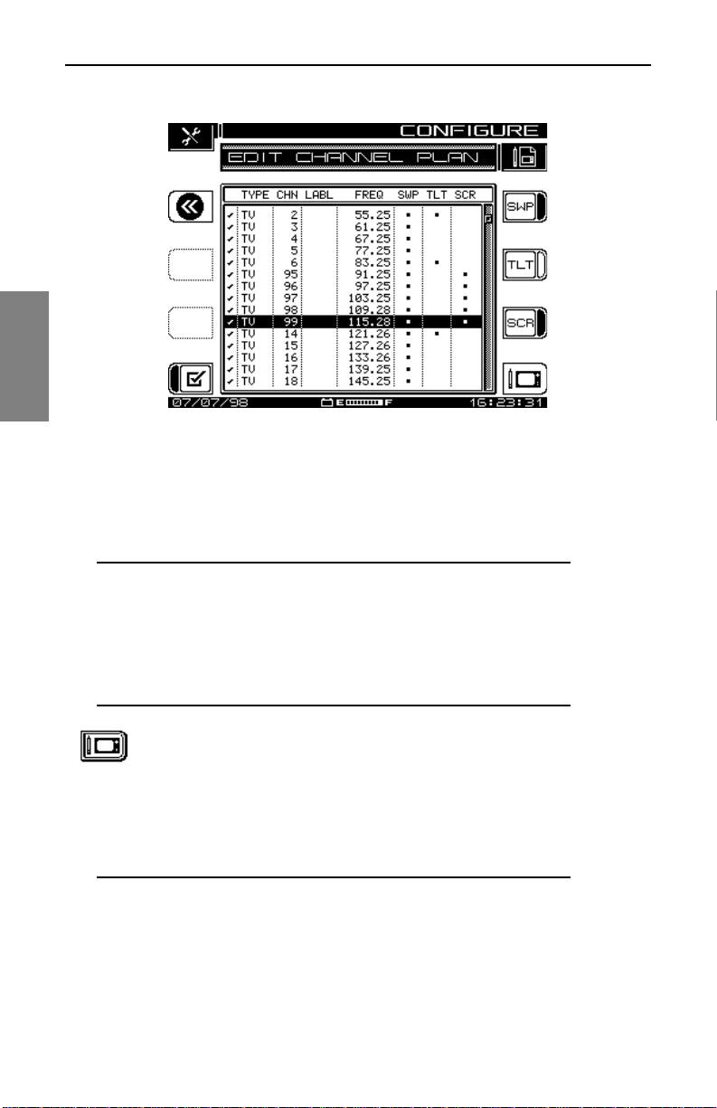
Channel Plans: Setting Channel Plan Parameters
3
Fig. 3-8 The EDIT CHANNEL PLAN Screen
The eight columns of this screen display the following information about
each channel in the plan, left to right:
Enabled; Type; Channel; Label; Frequency; Sweep; Tilt; Scrambled
44
NOTE: A check mark in the left margin means that the
channel is enabled; SWP, TLT, and SCR channels have
asterisks to indicate that status.
You can set the sweep, tilt, and scrambled attributes from
this screen using the soft keys to the right of the display, or
you can edit them from the EDIT CHANNEL menu.
2. Press the E dit Channel soft key, and the screen in Fig.
3-9, EDIT CHANNEL, appears.
The EDIT CHANNEL screen presents, one-at-a-time, a
listing of the channels in the current plan in numerical or
frequency order , dependin g on the channel tuning sequence
you selected (see “Channel Tuning Sequence” on page 40).
NOTE: For each channel there is a list of up to 12
parameters you can examine or adjust. Use the up and
down diamond keys to scroll, select, and to uncover the
10th, 11th, and 12th parameters, if present.
Page 69

Channel Plans: Setting Channel Plan Parameters
Use the left and right di amond keys, or the tw o arrow ico ns
at the uppe r right corner, to scroll through the list of
channels.
Fig. 3-9 The EDIT CHANNEL Screen
3
NOTE: If you want to configure a digital carrier in your
channel plan, follow the instructions in the section
“Configuring a Digital Carrier” at the end of this section.
3. Select the parameter you want to change. (The following
section, “Editable Parameters,” provides a description o f
each paramet er.) You make adjustments to the highlighted
parameter by pressing the Enter soft key, making the
changes, then pressing Enter again.
4. Press the Add soft key to add a new channel to the plan.
The new channel will be assigned the next channel num ber
from the one being viewed, and a frequency set to the
smallest in the channel plan (5 MHz).
5. Press the Delete soft key to remove the current channel
from the plan. The screen warns you about the deletion.
6. When you have finished editing the channel/frequency in
this screen, press the Return soft key to return to the EDIT
CHANNEL PLAN menu.
45
Page 70
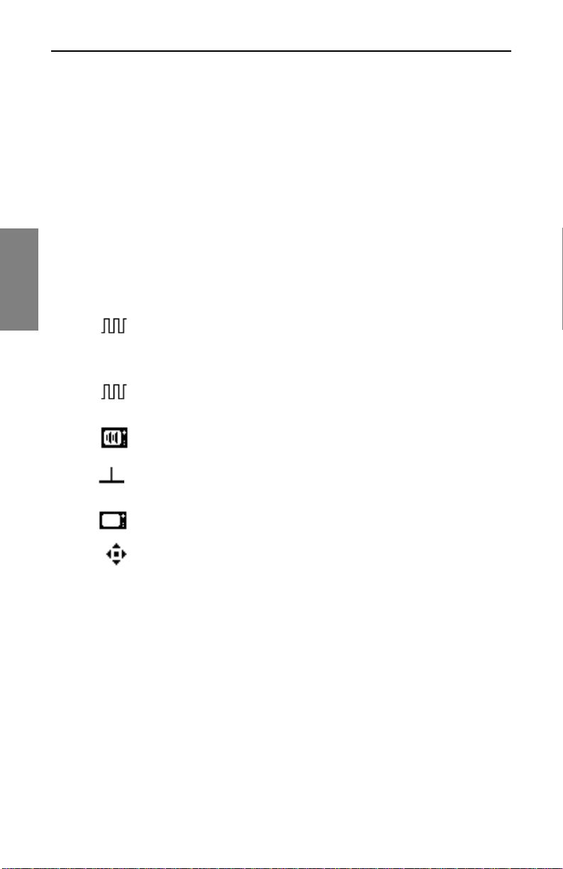
Channel Plans: Setting Channel Plan Parameters
Editable Parameters
• Enabled: This enables the instrument to monitor the channel. Select
Yes or No. If the channel is not enabled it will not be included in any
measurement mode. At least one channel must be enabled.
• Type: When you select Type, the program offers six choices in the Edit
Box. Press the Enter soft key to highlight choices, and use the up and
down diamond keys to make the choice. For each of the choices
described below, the screen displays the appropriate channel
parameters for you edit if necessary. Channel type shows in the upper
display to the left of the channel number.
The six choices are described below. Table 3-1, “Carrier Types and
3
Parameters,” lists the parameters you can set for each type. The parameters
are described following Table 3-1.
• Digital Carrier (DIGITAL): Digital Carrier can be used for
continuous digital carriers. DIGI is supported only in the Level,
Sweep, Spectrum, and Scan measurement modes. An RMS
detection mode measures the level of a digital channel.
• QAM Digital Stream (QAM): Use QAM for QAM 64 or 256
digital carriers.
• Video + Dual Audio Channels (DUAL): DUAL is a European
system, incorporating video plus two independent audio carriers.
• Single Carrier (SINGLE): SNGL can be used as a carrier for FM
or data.
46
• Video Channel (TV): Video Cha nnel includes the standard video
carrier with audio carrier offset.
• Sweep Insertion Point (SWEEP): This type enables the
channel for use as a sweep insertion point.
Page 71
Enabled
Channel Plans: Setting Channel Plan Parameters
Table 3-1 Carrier Types and Parameters
Digital
Carrier
(DIGI)
QAM
Digital
Stream
(QAM)
✔ ✔ ✔ ✔ ✔ ✔
Video +
Dual
Audio
Channels
(DUAL)
Single
Carrier
(SNGL)
Video
Channel
(TV)
Sweep
Insertion
Point
(SWP)
Type
Frequency (MHz)
Channel Number
Label
Sweep Channel
Measurement
Bandwidth (MHz)
Noise Offset (MHz)
Tilt Channel
Scrambled
Audio Offset 1
(MHz)
Audio Offset 2
(MHz)
Modulation
Symbol Rate
Standard
✔ ✔ ✔ ✔ ✔ ✔
✔ ✔ ✔ ✔ ✔ ✔
✔ ✔ ✔ ✔ ✔
✔ ✔ ✔ ✔ ✔
✔ ✔ ✔ ✔ ✔
✔ ✔ ✔ ✔
✔ ✔ ✔ ✔ ✔
✔ ✔ ✔
✔ ✔
✔ ✔
✔
✔
✔
✔
3
Spectrum Inversion
✔
• Frequency (MHz): Th is p aram et er se t s th e freq uen cy of the carrier (for
TV and DUAL types, thi s i s the freq uen cy of the video carrier). Pre ss the
Enter soft key and enter the frequency by using the numeric keypad or
the up and do w n di am ond k ey s. Th en p r ess the Enter sof t k ey t o commit
the entry.
47
Page 72

Channel Plans: Setting Channel Plan Parameters
• Channel Number: This is the channel number of the carrier. Change
the channel number by pressing the Enter soft key and using the
numeric keypad or the up and down diamond keys. Press the Enter soft
key to save the entry.
• Label: You can create a distinctive label of up to four characters to
attach to the channel’s number. The label associates the channel’s
number to programming. Use the Enter soft key, the keypad or the up
and down diamond keys. The diamond keys allow you to use special
characters. The label appears to the left of the channel number on most
screens.
• Sweep Channel: Sweep Channel designates whether the channel will
be used for Sweep measurements. Use the Enter soft key and the up
3
and down diamond keys to select Yes or No.
• Measurement Bandwidth (MHz): To edit the bandwidth, select
Measurement BW. Adjust bandwidth by using the up and down arrow
keys or by entering a val ue using the n umeric keyp ad. U se th e Enter sof t
key to start and finish. On a digital channel, this is the bandwidth of the
carrier to be measured.
NOTE: In the United States, the FCC specification for C/N
measurements is a bandwidth of 4.00 MHz. Cable
Television organizations outside of the United States may
have different requirements.
• Noise Offset (MHz): The frequency at which the noise level is
measured is the carrier frequency plus the noise offset. To adjust the
noise offset, select Noise Offset (MHz). Adjust the offset by using the up
and down diamond keys or by entering a value using the numeric
keypad. Use the Enter soft key to start and finish.
• Tilt Channel: Tilt Channel designates whether or not the channel is to
be used for the Tilt mode. Up to nine channels can be designated as Tilt
channels. Use the up an d dow n dia mo nd k eys to se lect either Yes or No
and the Enter soft key to begin and end data entry.
• Scrambled: The Scrambled item indicates whether the channel is
scrambled. Use the Enter soft key to begin editing, and the diamond
keys to select either Yes or No. Press Enter again to save the setting.
48
Page 73

Channel Plans: Setting Channel Plan Parameters
TIP: To increase sweep speeds, a st able au dio carri er can
be used as a sweep point.
Sweeping and measuring a scrambled channel is slower
than an unscrambled channel. Add a “SINGLE” type
channel at the frequency of the audio carrier and enable
this channel for sweep. For a scrambled channel, a
diamond appears in the LCD title bar to the left of the
channel-type indicato r on most sc reen s.
• Audio Offset 1 (MHz): This setting specifies the audio offset of the
channel. Use the up and down diamond keys or the keypad to edit the
setting and the Enter soft key to begin and end the entry.
• Audio Offset 2 (MHz): This specifies the offset for the second audio
carrier of a Dual channel. Use the up and down diamond keys or the
keypad and the Enter soft key to begin and end the entry.
• Modulation: This setting is used to specify the QAM modulation used.
You can select either 64 or 256 QAM.
• Symbol Rate: This specifies the information rate of the channel. This
rate is expressed in “millions of symbols per second” (Msym/s) and may
be edited in the Digita l Summary Mo de. The defaul t for 64 QAM is 5.0 57.
The default for 256 QAM is 5. 360. Edits to the default symbol rate shou ld
be made only when more accurate data is obtained from equipment
specifications or further analysis of the signal.
3
• Standard: Standard refers to the sign al st andard u sed. An nex A i s used
primarily in Europe, Annex B is used in the US, and Annex C is used in
Japan. If your channel plan is NCTA, the unit defaults to Anne x B ; if yo ur
plan is PAL, it defaults to Annex A. Your choices are Annex A (DVB),
Annex A (DAVIC), Annex B, and Annex C.
• Spectrum Inversion: S pectrum Inversion desi gnates whether or no t the
signal is inverted.
Configuring a Digital Carrier
This section walks you through the process for setting up digital channels in
your channel plan.
NOTE: The SDA now simplifies digital channel setup.
When you’re changing a TV type channel to DIGI or QAM,
the unit automatically sets the frequency to the center of
49
Page 74

Channel Plans: Setting Channel Plan Parameters
the digital channel’s bandwidth, and changes the
Measurement BW set ting approp riately. If you change from
a DIGI or QAM chan nel to a TV type, the units a ls o a dju st s
these settings for you.
1. From the EDIT CHANNEL PLAN screen (Fig. 3-8), select the channel
that you are going to configure as digital, then press the Edit Channel
soft key or the Enter keypa d key.
2. Highlight the Type item from the list of parameters and press Enter.
3. Use the diamond keys to select DIGI.
4. The Frequency (MHz) line in the parameters list will default to the
3
center frequency of the digital channel bandwidth.
5. Using the numeric keypad, enter the center frequency of the digital
carrier, then press the Enter soft key.
6. Highlight the Measurement BW (MHz) item from the parameters list.
7. Using the numeric keypad, type the bandwidth of the digital carrier,
and then press the Enter soft key.
8. Now select the Enabled line from the parameters list and verify that
the setting is Yes.
9. Press the Exit soft key.
10. Highlight the next channel to be configured as digital, and repeat this
procedure.
Configuring for Inverted Spectrum
• Inverted Spectrum and Signal “Lock”: During the modulation and
demodulation of the forward transmission of a digital stream, the
spectrum inverts many times – meaning that it “flips” or mirrors the image
of itself. If the SDA does not properly “lock” onto a selected QAM
channel, the cause may be spectrum in version.
TIP: You can configure individual QAM channels in the
Channel Plan to correct inverted spectrums when they
occur (See Base Channel Plans and Spectrum Inversion
below).
• Base Channel Plans and Spectrum Inve r sion : When you select the
Base Channel Plan used by the SDA (NCTA, P AL-UK, etc.), you are also
50
Page 75
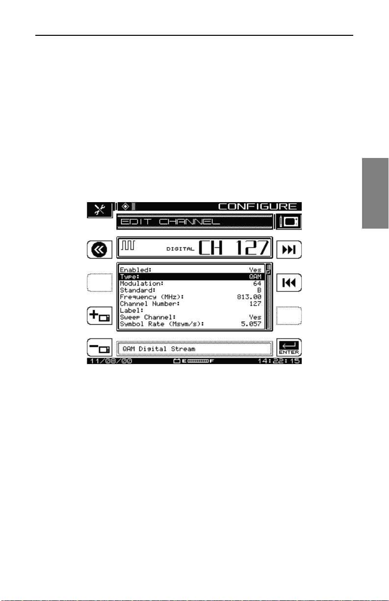
Channel Plans: Setting Channel Plan Parameters
selecting the unit’s default setting for Inverted Spectrum, which is simply
“Yes” or “No”.
• For example, when you select the NCTA channel plan, the SDA defaults
to Annex B and defaults to “No” regarding Inverted Spectrum because
the occurrence of spectrum inversion is not anticipated. If spectrum
inversion does occur, however, the setting can be edited to “Yes” on the
Edit Channel screen.
• The PAL-UK channel plan defaults to Annex A and to “Yes” for Inverted
Spectrum because spectrum inversion is anticipated with PAL-UK
channels. All other Base Channel Plans default to “No” for Inverted
Spectrum (because spectrum inversion is not anticipated).
3
Fig. 3-10 EDIT CHANNEL Menu Screen (Type: QAM)
Configuring a QAM Digital Stream Channel
1. From the EDIT CHANNEL PLAN screen, select the channel to be
configured as a QAM Digital Stream channel and press the Enter key
on the keypad.
2. Press the down diamond key to highlight Type from the EDIT
CHANNEL menu and press Enter to edit the current selection. Use
the down diamond key to select QAM Digital Stream and press Ent er
(see Figure 3-10).
3. Press the down diamond key to highlight Modulation and press Enter
to edit the curre nt select ion. Use the down diamond key to select 64 or
256 QAM and press Enter.
51
Page 76
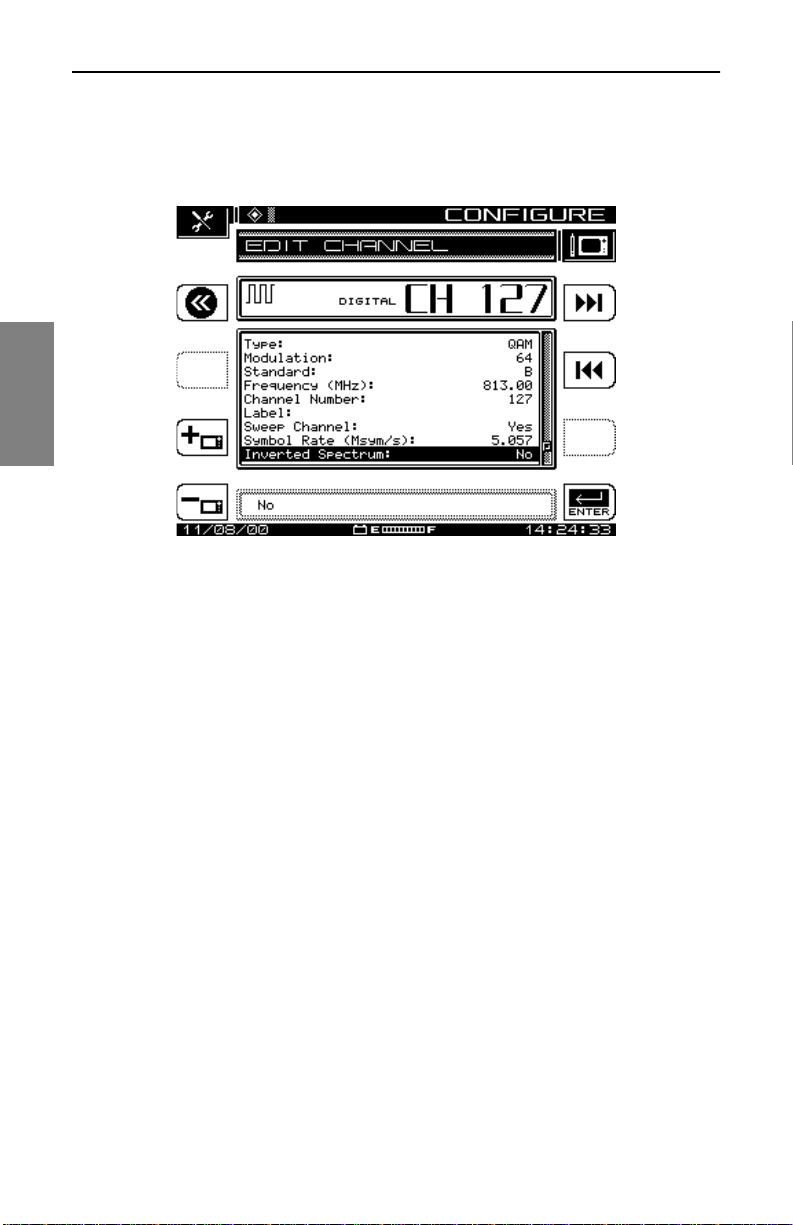
Channel Plans: Setting Channel Plan Parameters
4. Press the down diamond key to highlight Standard and press Enter to
edit the current selection. Use the down diamond key to select the
appropriate Signal Standard and press Enter.
3
Fig. 3-11 EDIT CHANNEL Menu Screen (Inv erted Spec trum)
5. To edit other channel parame ters on th e m enu as necessary (such as
Frequency, Channel Number, Label, Sweep Channel, Symbol Rate,
and Noise Offset) follow the same process: Press the down diamond
key to highlight the selection to be edited, press Enter, use the down
diamond key to edit the parameter or the keypad to enter the
appropriate data, and press Enter to select it.
6. If the default setting for Inverted Spectrum is incorrect, press the
diamond key to highlight Inverted Spectrum and press Enter to edit
the current selection. Use the down diamond key to select the
alternate choice, and press Enter (see Figure 3-11).
7. Repeat this process as necessary to configure each QAM Digital
Stream channel in your channel plan.
Inverted Spectrum Features
• Frequency Tuning: When frequency tuning in the QAM measurement
modes, the QAM signal is demodulated as a non-inverted spectrum.
• Channel Plans: When using the soft key to add a new channel to the
channel plan, the new channel will be assigned the next channel
number. If the initial channel is a QAM channel, the new channel will
receive the initial setting for Inverted Spectrum.
52
Page 77

Channel Plans: Setting Channel Plan Parameters
• When copying channel plans from unit to unit:
• If both units have the current firmware, all of the channel plan
information, including Inverted Spectrum, is ma intained.
• If the unit sending the channel plan is ol der than SDA v2.5 (no Inve rted
Spectrum option), the Inverted Spectrum setting for all QAM channels
will be defaulted to “No”.
• If the unit receiving the channel plan is older than SDA v2.5 and the
sending unit is SDA v2.5 or above, the Inverted Spectrum setting will
be omitted.
• StealthWa re: StealthWare does not support the In verted Spectrum
setting.
• When receiving a channel plan from StealthWare, units with SDA v2.5
or above will default to an Inverted Spectrum setting of “No”.
• When sending channel plans to StealthWare, the Inverted Spectrum
setting in QAM channels will be ignored.
Delete Unused Channels
CAUTION ! Never delete unused channels until sweep
points are made.
3
After the plan has been built, you can delete unused channels, if
appropriate. Doing this frees memory for other uses and cleans up the
channel plan.
1. Select Delete Unused Channels in the CHANNEL PLAN menu (see
Fig. 3-2), and press the Continue soft key.
2. The screen warns you that the deletion cannot be undone, that ALL
channels not enabled will be del eted.
3. Press the OK soft key to delete unused channels, then press the OK
soft key again to return to CHANNEL PLAN menu.
Specify Auto Measurements
This option enables you to specify one or all of three measurements (C/N,
Hum, Mod) for inclusion with any TV channels in your plan.
53
Page 78
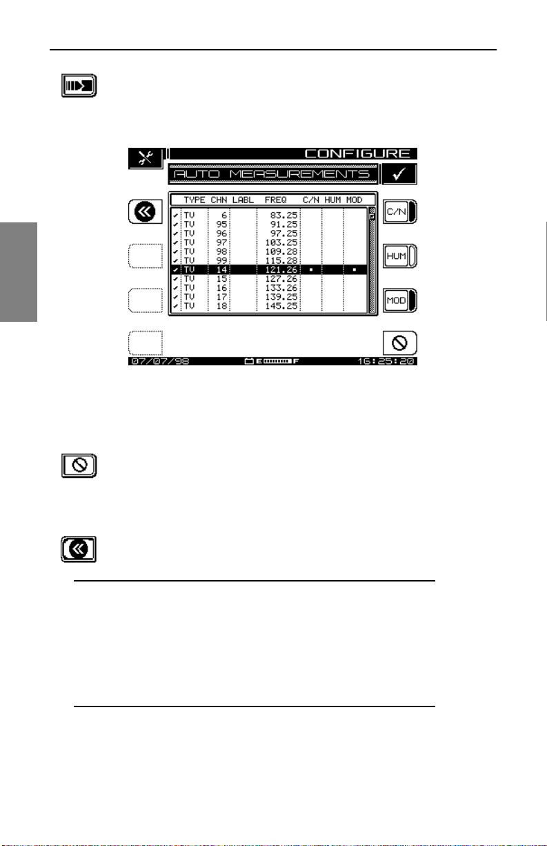
Channel Plans: Setting Channel Plan Parameters
1. Select Specify Auto Measurements from the CHANNEL
PLAN menu and press the Continue soft key. The screen
shown in Fig. 3-12, AUTO MEASUREMENTS, appears.
3
Fig. 3-12 The Auto Measurements Screen
2. Use the up and down diamond keys to scroll through the
listed channels.
54
3. Use the bottom right icon’s soft key to program all three
measurements for a channel, or use the C/N, Hum, and
MOD soft keys separately. When the lower right icon
changes to a slotted ci rcle, yo u can use it to cance l all three
tests for a selected channel.
4. Press the backup icon soft key at the upper left to return to
the CHANNEL PLAN menu.
NOTE: Keep in mind:
• C/N, hum, and modulation cannot be measured on a
scrambled channel or a digital carrier.
• Hum measurements include all components < 1 kHz.
• Hum is measured in either % or dB, as established
during setup.
Page 79
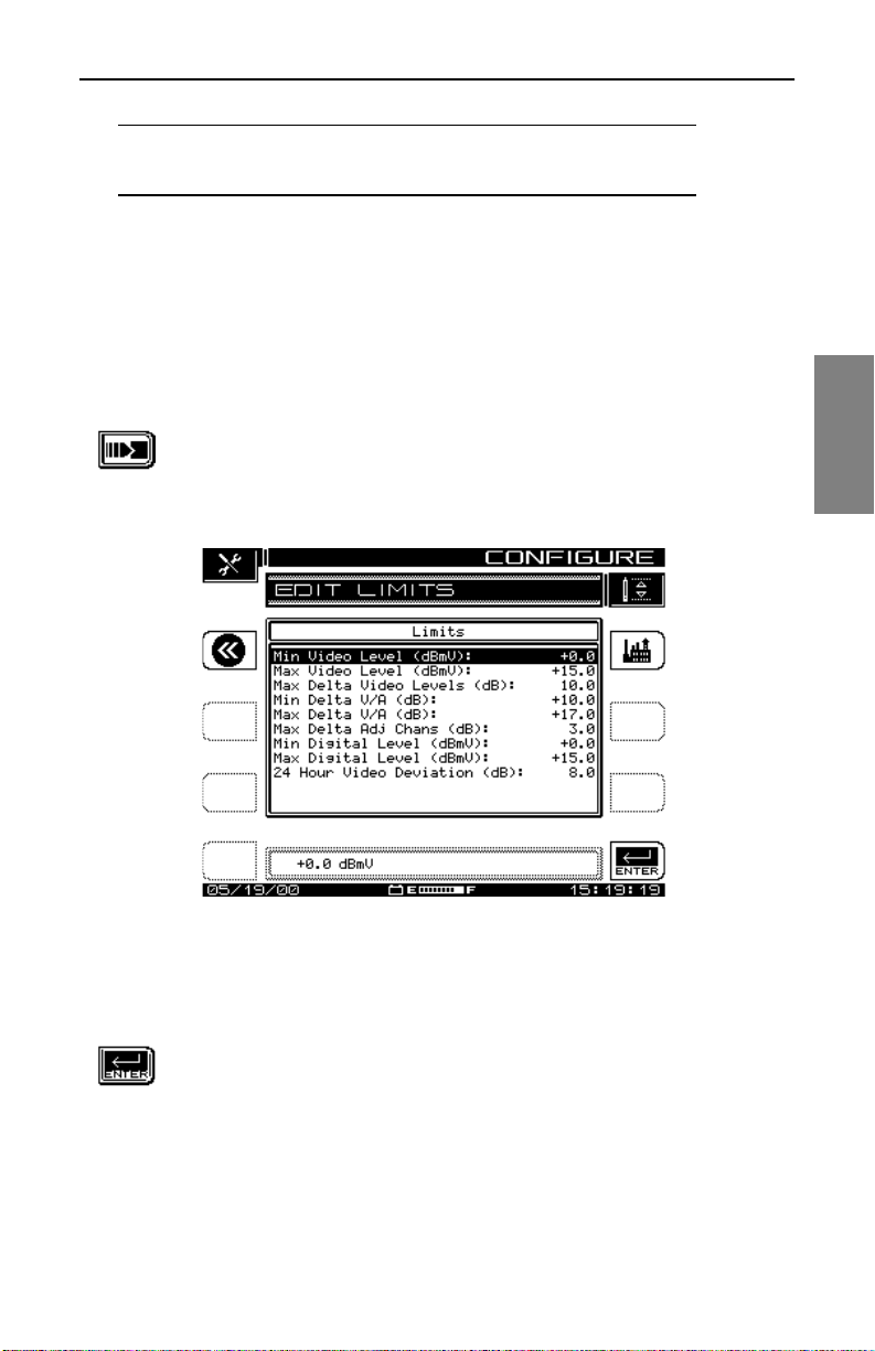
Channel Plans: Setting Channel Plan Parameters
CAUTION ! Units cannot be changed after the Auto Test
has been completed!
Edit Limits
Use the Edit Limits option of the CHANNEL PLAN menu to establish
standards to be incorporated into an Auto Test. As the Auto Test
measurements are running, the program compares measured values to the
limits you set for Video Level, Level Delta values, Digital Level, and Max 24hour Level deviation.
1. From the CHAN NEL PLAN menu shown in Fig. 3- 2, scroll to
the Edit Limits item and press the Continue soft key. The
screen shown in Fig. 3-13, EDIT LIMITS, appears.
3
Fig. 3-13 The Edit Limits Screen
2. Use the up and down diamond keys to select the limit to be
edited.
3. Press the Enter soft key to begin, then use the numeric
keypad or t he up an d down diamon d keys to make the entry.
When you have made the adjustment, press the Enter soft
key again to save the setting and update the dis pl ay.
55
Page 80
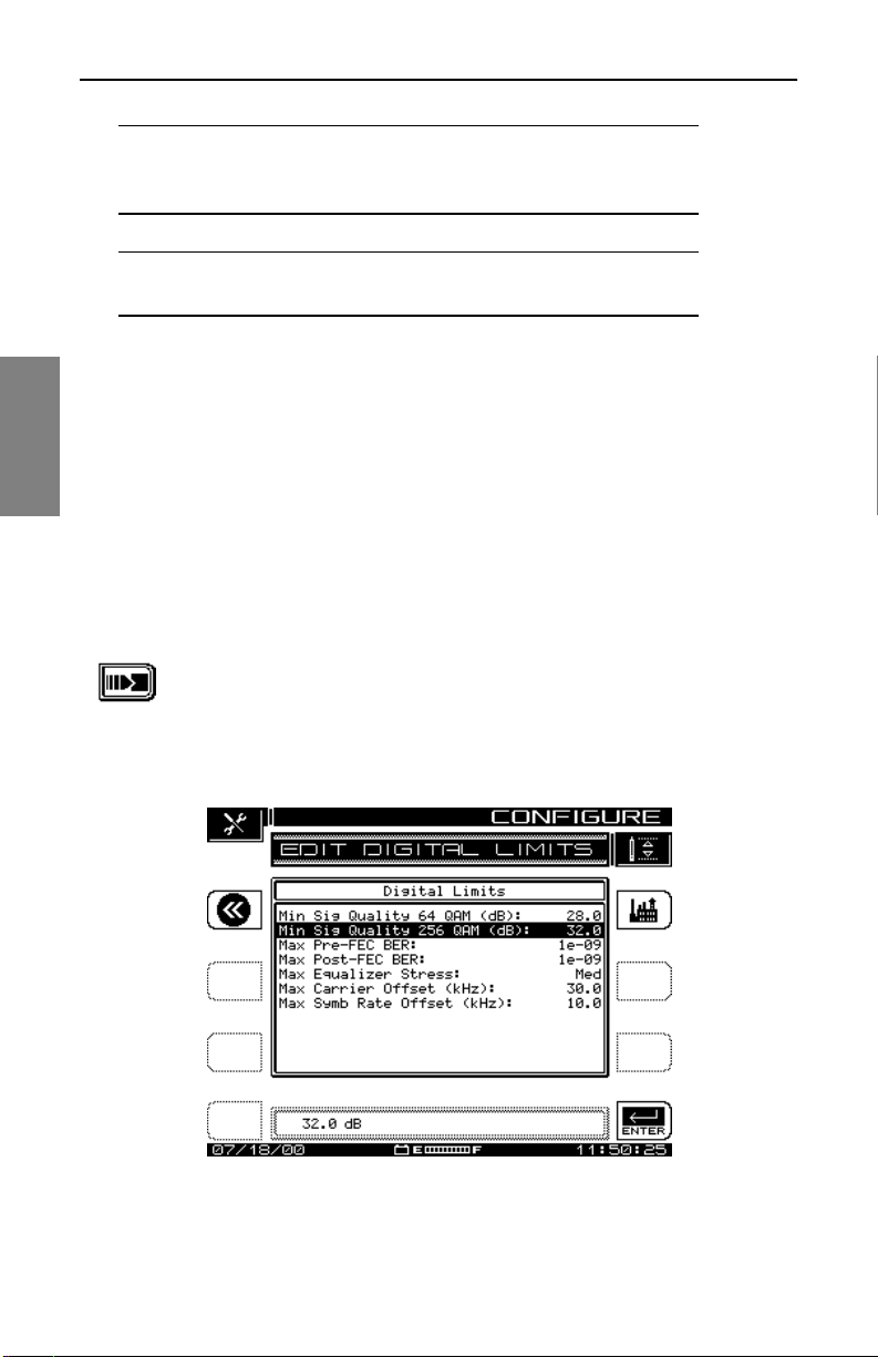
Channel Plans: Setting Channel Plan Parameters
NOTE: You can use the Factory ico n so f t ke y at the upper
right of the screen to set FCC (US) recommended default
values automatically.
NOTE: You cannot use the Factory icon to set FCC
recommended values when you’re setting Digital Limits.
Edit Digital Limits
3
The Edit Digital Limits option on the CHANNEL PLAN menu appears only if
your SDA unit is equip ped with the QAM opti on (OP T4). The p arameters yo u
set here are compared to the measurements displayed in the Digital
Summary and digital Detail screens in QAM Mode.
See Also
½ Chapter 9, Digital Analysis (QAM View OPT4), describes
these modes in detail .
1. From the CHAN NEL PLAN menu shown in Fig. 3- 2, scroll to
the Edit Digital Limits item and press the Continue soft key.
The screen shown in Fig. 3-14, EDIT DIGITAL LIMITS,
appears.
56
Fig. 3-14 The Edit Digital Limits Screen
Page 81

Channel Plans: Setting Channel Plan Parameters
2. Use the up and down diamond keys to select the limit to be
edited.
3. Press the Enter soft key to begin, then use the numeric
keypad or t he up an d down diamon d keys to make the entry.
When you have made the adjustment, press the Enter soft
key again to save the setting and update the dis pl ay.
NOTE: You can use the Factory ico n so f t ke y at the upper
right of the screen to set all meas urement s in this screen to
the factory recommended default values.
Copy Remote Plan
This selection enables you to copy a channel plan from one meter to
another.
1. Confirm that each unit ’s baud setting i s the sa me. Althou gh the default
is 9600, Acterna recommends a baud of 19.2k for co pying plans. Then
connect a cable between the serial ports of two meters (this is a
special cable from Acterna).
2. From the CHANNEL PLAN menu, scroll to the Copy Remote Plan
item, and press the Enter soft key next to the Edit Box. A list of plans
located in the remote meter’s memory appears on the screen.
3. Select the plan that you want to copy and press the Copy soft key.
4. The selected plan is transferred from the remote meter and stored in
the meter that you are operating.
5. If there is a problem with the transfer, the screen notifies you.
3
57
Page 82

Channel Plans: Setting Channel Plan Parameters
3
58
Page 83

Chapter 4
Field Sweeping with the SDA-5000
INTRODUCTION
This chapter explains the SDA field units’ sweep function. You’ll first be
introduced to test point compensation. Next you learn how to configure the
field unit to compensate for test point losses and how to calculate those
losses. Configuring you r rece iv er for s weep is co ve red ne xt, after which you
learn about connecting the SDA-5000 to test points and how to perform
forward and reverse sweeps in the field. Finally, Sweepless and Loopback
sweeping are discussed.
See Also
½ Chapter 14, “SDA-5500/SDA-5510 Sweep Configuration,”
covers the sweep process in detail, as well as providing
information about how the headend and field units work
together to sweep the system.
TEST POINT COMPENSATION
In aligning a cable network, the important levels, the ones you should care
about, are the system levels within the coax and amplifiers. However, in
Page 84

Field Sweeping with the SDA-5000: Test Point Compensation
order to perform tests without cutting off service, it is necessary to use test
points. Test points are ports that tap off enough signal for monitoring, but
leave most of the si gna l i n th e s ys tem w he re it is needed. Typical test points
have 20-30dB of loss between the signal being measured and the port
output.
Additionally, it is sometimes necessary to inject or read signals in locations
other than the exact point of interest. If a signal is to be injected into a
reverse amplifier, there are usually some internal amplifier losses between
the test point and the actual amp input. It is also sometimes necessary to
use external pieces of hardware to combine or split signals from the field
meter before you connect to the system being tested.
Test point compensation accounts for these factors and allows the meter to
display true system levels, even though hardware between the system and
the meter may affect what the meter really sees. For example, if a forward
test point were 30dB lower than the coax line it tapped into, normal meter
readings would be 30dB below real system levels. Using test point
4
compensation, you can cancel out this effect. Though this simple example
would be easy to work out i n your head, more comp lex config urations c an be
far more challengi ng. Mete r test po int com pensatio n can help insure that you
interpret meter results correctly, with accurate results.
Test Point Compensation Configuration
NOTE: Test point compensation configuration has been
significantly changed and improved over previous
implementations. The new graphical displays for forward
and reverse test point compensation provide an at-aglance, simplified schematic of the test point connections
you must make and where test poi nt losses ar e gen erated.
This information is designed to help you better see
relationships among the various entries, and to help you
enter correct data for each test point loss location.
Test point compensation allows the SDA-5000 to show actual levels in the
cable network, even though some losses exist between the meter and the
network lines. The SDA-50 00 allows for s eparate adjustme nt of both forwa rd
and reverse test point losse s. The following ste ps show you how to configure
the SDA-5000 for test point compensation.
1. 1.To adjust and review these levels, press the and 7 stu keys to call
up the FWD COMPENSATION screen shown in Fig. 4-1. (You can
also use the NAVIGATOR interface’s TESTPOINT item to get to the
FWD COMPENSATION screen.)
60
Page 85
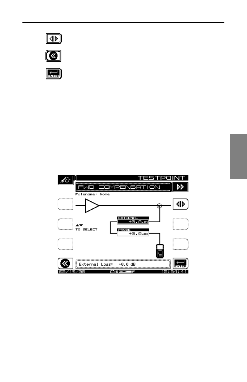
Field Sweeping with the SDA-5000: Test Point Compensation
Use the top right-hand soft key to toggle between
forward and reverse test point displays.
Use the top left-hand soft key to return to the previous
screen.
Use the bottom right-hand soft key to enter the current
value from the Edit Box into the test point loss table.
2. The forwar d test point display has two entries:
• The top item (EXTERNAL) is to allow for external pads, coupling
networks, or any amplifiers you might use. It is important to note that a
pad has a posit ive value (loss), whil e an ampli fier has a n egative v alue.
• You should enter the amplifier test point loss in the second line
(PROBE). Typically this is 20, 25, or 30dB. Positive values represent
loss, and are the norm. A negative value represents an amplifier.
Fig. 4-3 shows a 20dB test point, and an external splitter provides 3.5dB
additional loss.
4
Fig. 4-1 The FWD COMPENSATION Screen
3. The reverse t est point display contains more adjustments and
information (see Fig. 4-2).
The soft keys for this screen have the same function as those on the
FWD COMPENSATION screen, with the addition of an Information
soft key.
61
Page 86
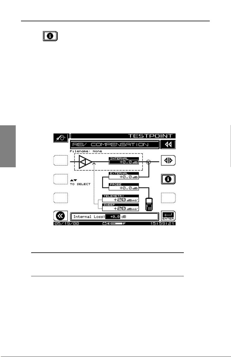
Field Sweeping with the SDA-5000: Test Point Compensation
Press this soft key to call up the TESTPOINT INFO
screen shown in Fig. 4-4. This screen provides
information for telemetry and sweep about transmitted
output levels, total losses, and actual and desired level s
and the delta between them.
4. To accurately calculate reverse test point loss, it’s helpful to have a
block diagram of the amplifier to be adjusted. When you’re balancing
constant input s to th e hybrid, the Internal e ntry re presents the internal
losses from the injection point to the hybrid. These losses (the top
entry box in the display) aris e from the various splitters , diplexers, and
so on, in the amplifier between the injection point and the amplifier
input. Test point, or probe, loss (the entry box third from the top in the
display) is the DC value of the test point.
4
62
Fig. 4-2 The REV COMPENSATION Screen
CAUTION ! Resistive test points should not be used for
reverse sweep. You might get inaccurate results because
of the presence of standin g waves.
External losses represent the components use d to c onn ec t to th e te st
point. For these values, positive numbers represent loss, which is the
norm. Negative values represent gain (a very rare event). This value
is entered in the box second from the top in the display.
Add all test point losses to get a total.
Page 87
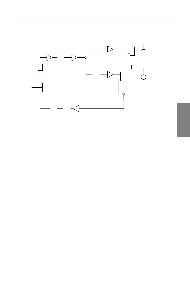
Field Sweeping with the SDA-5000: Test Point Compensation
I
As an example, consider the amplifier shown in Fig. 4-3:
PAD H
PAD
NPUT
EQ
PAD
PAD H
H
L
PADEQ
3.0dB
L
0.5dB
PAD
3.5dB
L
0.5dB
Test Point
20dB
OUTPUT
Test Point
20dB
OUTPUT
Fig. 4-3 Test Point Compensation Values
Measured at the test po int s avail able at the outpu t of the amp lifier, the
forward test point loss is 20dB. If you’re balancing constant inputs to
the hybrid, the reverse test point loss is 20dB for the test point, plus
1.0dB for a diplex er, plus 3.5dB for a splitter, plus the pad value at th e
input to the reverse amplifier (for example, assume 3dB). This would
be entered as 20dB of test point loss and 7.5dB of “internal” losses.
This value would be entered in the top data box in the display. In this
configuration, a splitter would be required to combine the two output
ports of the SDA-5000. This would be entered as 3.5dB of loss in the
external entry for both forward and reverse test point compensation.
5. The telemetry and sweep generation and injection levels are
displayed in the TESTPOINT INFO screen (see Fig. 4-4). The
generated levels are calculated based on the desired system levels
set at the main SWEEP configuration menu (see “Sweep
Configuration” on page 64), and the test point losses entered here.
The telemetry level is calculat ed precise ly for a spec ific frequenc y and
level. This value can be used with the headend display to perform
absolute level alignment, so it is calculated to 0.1dB resolution.
4
63
Page 88
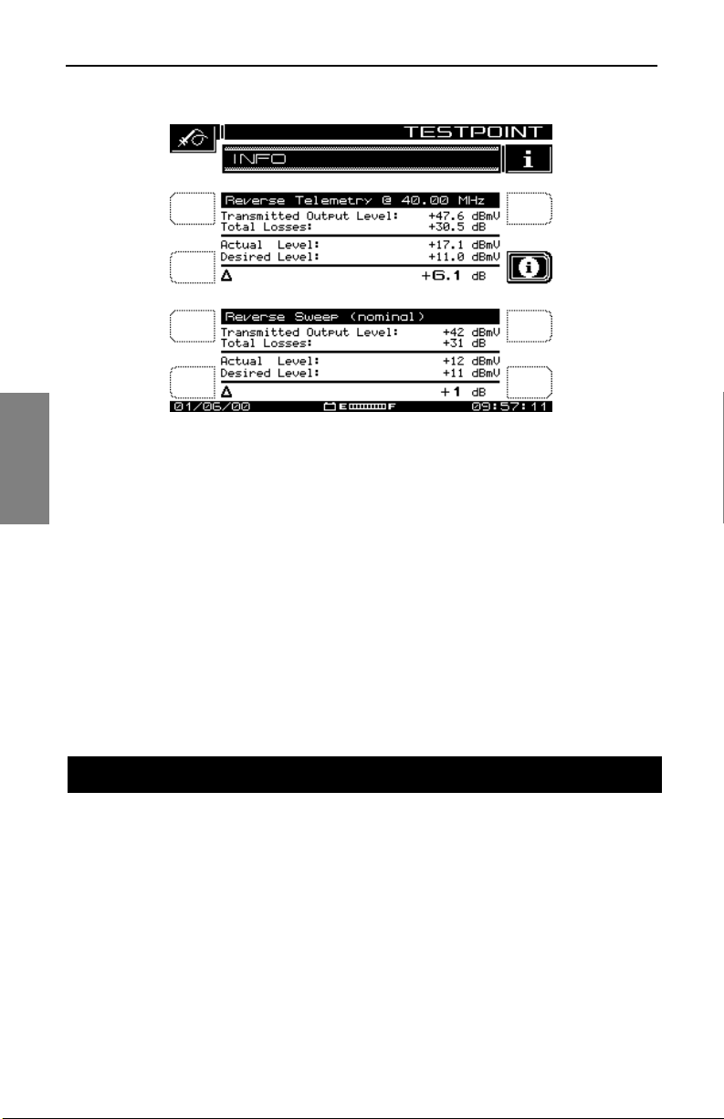
Field Sweeping wit h the SDA-5000: Sweep Receiver Configuration
4
Fig. 4-4 Telemetry and Sweep Generation and Injection Levels
The sweep injection level is a nominal value that is not corrected for
transmitter calibration because more than one frequency is used for
the pulses. For this reason, it is displayed only to the nearest 2dB.
When test point compensation changes, the output level of the
transmitter changes automatically to keep the system level of the
injected pulses the same. For example, if the test point values in Fig.
4-3 changed to 25dB, the transmitted output levels would move to
approximately 47dBmV to keep the system levels close to the same.
SWEEP RECEIVER CONFIGURATION
This section covers the configuration for sweeping, and presents details of
using the various controls and indicators provided by the SDA-5000 to
improve your efficiency.
Sweep Configuration
The SWEEP menu of the CONFIGURE ma in menu en ables you to es tabl ish
the operating parameters that you want for a specific sweeping application
(see Fig. 4-5). The first menu in this screen offers the options and choices
available in Stealth, Stealth (SDA COMPATIBLE), Transmit, Transmit (SDA
64
Page 89
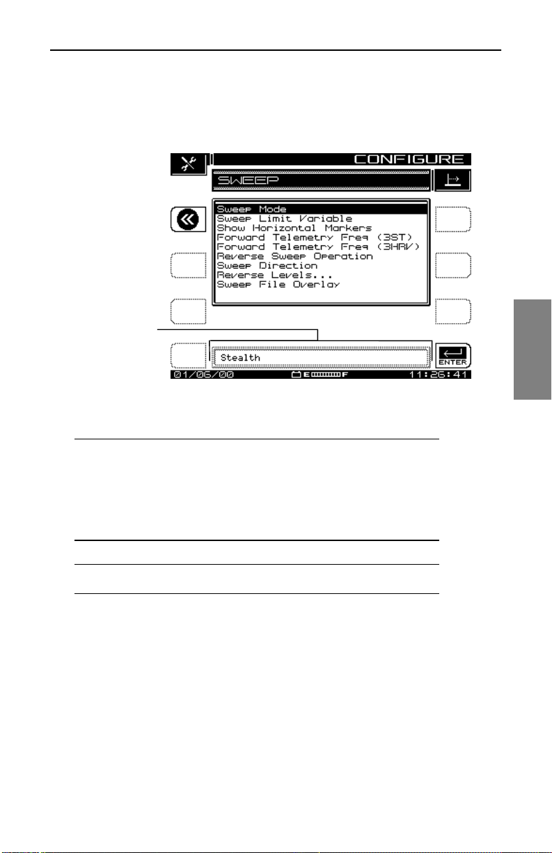
Field Sweeping w ith the SDA-5000 : Sweep Receiver Configuration
COMPATIBLE), Loopback, or Sweepless sweep modes. The number of
options available to you changes depending on which sweep mode you
select. Table 4-1, “Sweep Optio ns, ” lists your choices.
he Edit Box is
sed for data
ntry and mode
nd option
election
Fig. 4-5 The SWEEP Menu (Stealth Mode)
4
NOTE: When SDA Sweep mode is selected, Forward
Telemetry Freq (3ST) and Forward Telemetry Freq (3HRV)
become Forward Telemetry Freq (5500) and Forward
Telemetry Freq (5510) to remind you that you must be
using SDA equipment in both the headend and in the field
to use SDA Sweep mode.
NOTE: Stealth mode sweeping is the default setup.
65
Page 90
Field Sweeping wit h the SDA-5000: Sweep Receiver Configuration
Table 4-1 Sweep Options
Stealth
Sweep Mode Sweep Mode Sweep Mode Sweep Mode Sweep Mode Sweep Mode
Sweep Limit
Variable
Show
Horizontal
Markers
4
Forward
Telemetry
Freq (3ST)
Forward
Telemetry
Freq (3HRV)
Stealth
(SDA
Compatible)
Sweep Limit
Variable
Show
Horizontal
Markers
Forward
Telemetry
Freq (5500)
Forward
Telemetry
Freq (5510)
Transmit
(OPT2)
Forward
Telemetry
Freq
Forward
Sweep
Insertion
Level
Forward
Telemetry
Level
Include
Audio
Carriers
Transmit
(SDA
Compatible)
(OPT2)
Forward
Telemetry
Freq
Forward
Sweep
Insertion
Level
Forward
Telemetry
Level
Include
Audio
Carriers
Loopback
(OPT2)
Show
Horizontal
Markers
Sweep File
Overlay
Sweep
Insertion
Level
Loopback
Sweep Plan
Sweepless
Sweep Limit
Variable
Show
Horizontal
Markers
Include
Audio
Carriers
Sweep File
Overlay
Reverse
Sweep
Operation
Sweep
Direction
Reverse
Levels
Sweep File
Overlay
66
Reverse
Sweep
Operation
Sweep
Direction
Reverse
Levels
Sweep File
Overlay
Enable
Reverse
Sweep
Enable Live
Headend
Ingress View
Reverse
Telemetry
Level
Reverse
Sweep Plans
Enable
Reverse
Sweep
Enable Live
Headend
Ingress View
Reverse
Telemetry
Level
Reverse
Sweep Plans
Page 91

Field Sweeping w ith the SDA-5000 : Sweep Receiver Configuration
SWEEP Menu Options
• Sweep Mode: Use the up and down diamond keys to select Stealth,
Stealth (SDA COMPATIBLE), Transmit, Transmit (SDA COMPATIBLE),
Loopback, or Sweepless. Table 4-1 lists the range of choices in each
mode for each of the SDA options.
• Sweep Limit Variable: The Sweep Limit Variable is x in the response
flatness expression (n/10 + x) used during sweep measurements to
compare actua l system response to the form ula . x is adjustable from 0.0
to 5.0 (the default is 1.0). Use the up and down diamond keys or the
numeric keypad to enter a value.
• Show Horizontal Markers: The horizontal markers continuously track
maximum and minimum values in the area of the graph between the
vertical markers (see Fig. 4-10). Use the up and down diamond keys to
display the markers.
• Forward T elemetry Frequ ency: Use the up and down diam ond keys or
the numeric keypad to enter the forward telemetry frequency
corresponding to the SDA-5500.
NOTE: For successful Stealth mode operation, the SDA5000 telemetry frequency must match the transmit
telemetry frequency setting of the SDA-5500 transmitter.
CAUTION ! Do not place the telemetry signal too close to
the diplex filter cut-of f frequ ency. Roll-off may attenuate the
telemetry signal to the degree that communication fails.
This same caution applies to placing the signal in the highend roll-off region.
• Forward T elemetry Frequ ency: Use the up and down diam ond keys or
the numeric keypad to enter the forward telemetry frequency
corresponding to the SDA-5510.
NOTE: For successful operation, the SDA-5000 telemetry
frequency must match the forward telemetry frequency
setting of the SDA-5510.
CAUTION ! To prevent the SDA-5510 reverse sweep from
contending with the SDA-5500, disable the SDA-5500’s
4
67
Page 92

Field Sweeping wit h the SDA-5000: Sweep Receiver Configuration
reverse sweep and reverse noise features. This will speed
up the SDA-5500’s forward sweep. Also, be sure the
telemetry frequencies of the headend units are different.
• Forward Sweep Insertion Level (T rans mit and SDA Compatible
Transmit (OPT2) modes only): This is the level at which sweep
insertion points wi ll be inserted; 40 or 50 dBmV is the max. Sweep point s
should be 14-16 dB below the video refere nce level . Sweep point s fall on
the video and/o r au dio frequency of unu se d c hannels by default , b ut c an
be moved.
• Forward Telemetry Level (Transmit and SDA Compatible Transmit
(OPT2) modes only): This setting determines the level of the telemetry
signal (FSK). This should be set 10 dB below the video reference level.
The telemetry level is adjustable from 20-50 dBmV in 2 dB increments.
The max is 50 dBmV, however some older units may have a max of 40
dBmV.
4
• Enable Reverse Sweep (Transmit and SDA Compatible Transmit
(OPT2) modes only): This setting allows reverse sweep to operate in
the Transmitter. If it’s disabled, forward sweep will be faster but reverse
sweep will be inoperable.
• Enable Live Headend Ingress View (Transmit and SDA Compatible
Transmit (OPT2) modes only): When enabled, this setting allows
reverse noise to be transmitted on the forward telemetry. If it’s disabled,
the forward sweep will be faster.
• Reverse Sweep Operati on (Stealth and SDA Compatible Stealth
modes only): Sel ect Si ngle User fo r reve rse o peratio ns as soci ated with
a SDA-5500. Select Multiple Users for reverse operations associated
with a SDA-5510.
• Sweep Direction (Stealth and SD A Compatible S tealth modes only ):
There are two possible sw eep directio ns on SDA-5000 field units with the
reverse sweep option (OP T1): Forwar d and Reverse. Use th e Edit Box to
select the direction desired, and then press the Enter key.
NOTE: When sweeping, you can change direction by
simply pressing the left diamond key for reverse, or the
right diamond key for forward sweeping.
• Reverse Telemetry Level (Transmit and SDA Compatible Transmit
(OPT2) modes only): The reverse telemetry level is the level of the
carrier that the SDA-5000 uses to transmit telemetry data. Use the Edit
68
Page 93

Field Sweeping w ith the SDA-5000 : Sweep Receiver Configuration
Box to set the Reverse Telemetry Level to an appropriate value. When
adjusting the Reverse Telemetry Level, set the level to the desired
insertion level after loss. The value used includes test point
compensation.
• Reverse Levels: This option takes you to the REV COMPENSATION
screen. From this screen you can set test point losses and the reverse
telemetry and reverse sweep insertion levels.
• The reverse telem etry level i s the lev el of the carri er that the S DA-5000
uses to transmit telemetry data. Use the Edit Box to set the Reverse
Telemetry Level to an appropriate value. When adjusting the Reverse
Telemetry Level, set the level to the desired insertion level after loss.
The value used includes test point compensation.
NOTE: The frequency of the reverse telemetry carrier is
set on the headend unit. There is no Reverse Telemetry
Frequency setting available from the field unit.
• The revers e sweep insertion level is the level at which the unit inserts
(transmits) sweep points. All sweep points are inserted at the same
level. Use the Edit Box to set the Reve rse Swe ep In se rtio n Lev el to an
appropriate value. (Typically this is at a maximum of +50 dBmV to
overcome test point loss, not including the test point compensation
setting.)
4
NOTE: The reverse sweep plan, which is set on the
headend unit, defines the frequencies at which the sweep
points are ins erted. The sweep point frequenc ies cannot b e
adjusted on the field unit.
• Reverse Sweep Plans (Transmit and SDA Compatible Transmit
(OPT2) modes only): Reverse sweep plans are built and/or edited for
the upstream direction. The reverse channel plan must be set up on the
Transmi tter. It will be automatically commun icated to the fie ld unit v ia the
forward telemetry.
• Sweep File Overlay: Sweep file overlay enables you to view a stored
sweep response simultaneously with a “live” sweep response for direct
comparison. The sweep file overlay option must be enabled for viewing
both traces simultaneously. With this option disabled, stored files are
displayed for normal viewing without the live response superimposed. If
the sweep file overlay option is enabled, the live response overlays the
69
Page 94

Field Sweeping wit h the SDA-5000: Co nsiderations for Sw eep in the Field
stored response during viewing. Use the up and down diamond keys to
enable the option.
• Include Audio Carriers (Transmit (OPT2) and Sweepless modes
only): This selection allows the audio carriers to be excluded, resulting
in a faster sweep. Us e the up and dow n diamon d keys to inc lude (Yes) or
exclude (No) audio carriers.
• Sweep Insertion Level (Loopback (OPT2) mode only): This is the
level transmitted for eac h Loopback s weep point. The va lue entered here
is determined by the signal level units specified in the MEASUREMENT
configuration screen (see “Me asu rem en ts Configuration” in Chapter 2,
page 25). This level is adjustable from 20 dBmV to 50 dBmV with a
stepsize of 2; the default is 20 dBmV.
• Loopback Sweep Plans (Loopback (OPT2) mode only): This
selection allows you to create and edit the Loopback Sweep Plan.
4
CONSIDERATIONS FOR SWEEP IN THE FIELD
The Sweep function has f our operati ng mo des, Stealth, Transmit, Loop ba ck,
and Sweepless. The current sweep mode is indicated in the upper righthand corner of the screen (see Fig. 4-10). The Stealth mode allows sweep
insertion points to be injected in vacant spectrum areas. The Loopback
mode enables you to perform a rough frequency response, gain, and loss
test on active and passive devices in the field. The Sweepless mode only
measures actual system carriers. Any system carrier can be used as a data
point, even scrambled or digital carriers. In either mode , a previou s ly stored
response can be used as a reference to the current measurement. Sweep
references are selected in the File setup menu (see “Sweep References” in
Chapter 11, page 201). The Transmit mode operates the same as the Scan
mode with these exceptions: sweep telemetry is transmitted, sweep points
are inject ed, and sweep point levels are displayed (see “Scan
Measurements” in Chapter 6, page 115).
Connecting the SDA-5000 to a Test Point
This section covers signal level issues and shows you how to interface with
different ne twork architectures.
70
Page 95

Field Sweeping with the SDA-5000: Considerations for Sweep in the Field
Signal Level Considerations
At amplifier test points, the same basic connection and signal level rules
apply to the SDA-5000 as apply to the headend unit. Too much signal level
on the input of the unit can cause inconsistent sweep readings. The forward
telemetry level should be 0dBmV±12dB at the input of the SDA-5000. This
can be verified by checking the lower right corner of the unit’s display while
sweeping forward (see “Forward Sweep Operation” on page 75). If the
telemetry level is too high, adding in-line attenuators or pads on the unit’s
input is a quick way to reduce signal level.
See Also
½ Chapter 14, “SDA-5500/SDA-5510 Sweep Considerations”
discusses the connecti on and signal level issues for
headend units.
If both the SDA-5500 and SDA-5510 units are in service, telemetry
frequencies for both the headend and field units must be entered during the
setup of the field units.
NOTE: The field units must als o be set to the multi ple user
mode (if you’re using the SDA-5510), even if only one of
the maximum ten people are sweeping.
4
Wiring and Levels: Forward Sweep
Only one cable is required for forward sweep testing. Simply connec t a test
point from the output of the amplifier to be aligned or tested to the IN port of
the SDA field unit. If the video carriers in the signal are above +20 dBmV in
the signal after test point loss, then you should use an inline pad to drop the
level to no more than +10dBmV v ideo carri er levels. (Typically this will be the
case only when direct connections to an amplifier output are used.)
NOTE: Remember, as stated previously, too much signal
level on the input can cause inconsistent sweep readings.
The forward telemetry level should be 0dBmV ± 12dB on
the input of the SDA field unit. This can be verified by
checking the lower right corner of the unit’s display while
sweeping forward. Inline pads provide a quick way to
reduce the signal level on the input.
71
Page 96
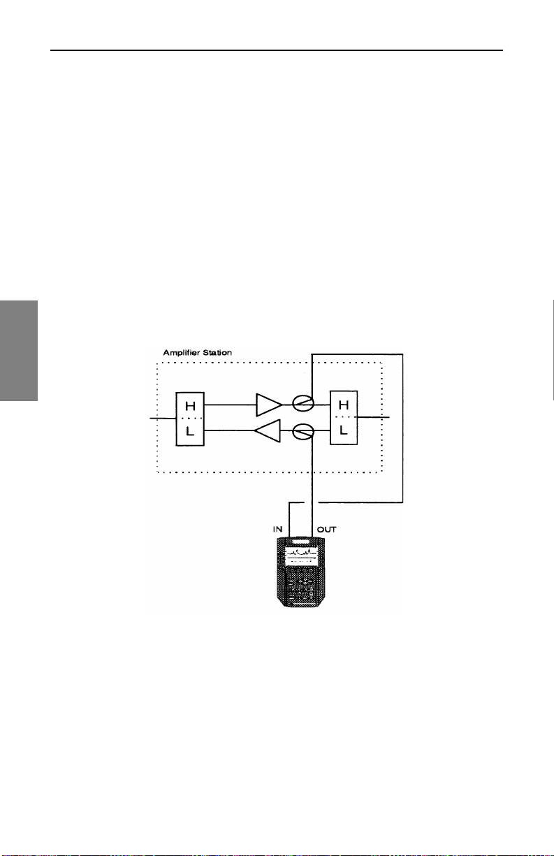
Field Sweeping wit h the SDA-5000: Co nsiderations for Sw eep in the Field
Wiring and Levels: Reverse Sweep (SDA-5000 OPT1)
You can use several connection methods for reverse sweep, depending on
system engineering methods and equipment.
• Split band networks: Most networks are split band network
architectures, where one set of frequencies is used for forward signals
(typically the higher frequencies above 50-80MHz), and another set is
used for reverse path signal s (typic ally the lower frequen cies from 5MHz
to below the start of forward path signals at 30-65MHz). These signals
are combined on t he same p iece of coax , and spe cial amp lifiers in crease
selected bands in different directions. In a split band system, the most
reliable and accurate method is to use two test points, one for forward
path signals (to receive the sweep telemetry signal), and a second for
reverse path signal injection. An example of this connection is shown in
Fig. 4-6.
4
Fig. 4-6 SDA-5000 Connected in a Network with Two Test Points
When two separate test points are not available, you can use a splitter or
diplex filter to combine the two SDA field unit ports and connect them to a
single point. An example of this connection is shown in Fig. 4-7.
It is important to use a directional test point of some sort for reverse sweep
injection. Fals e s t a ndi ng waves and level in ac curacies can resul t fro m try ing
to sweep with resistive reverse test points. This is not a sweep system
72
Page 97
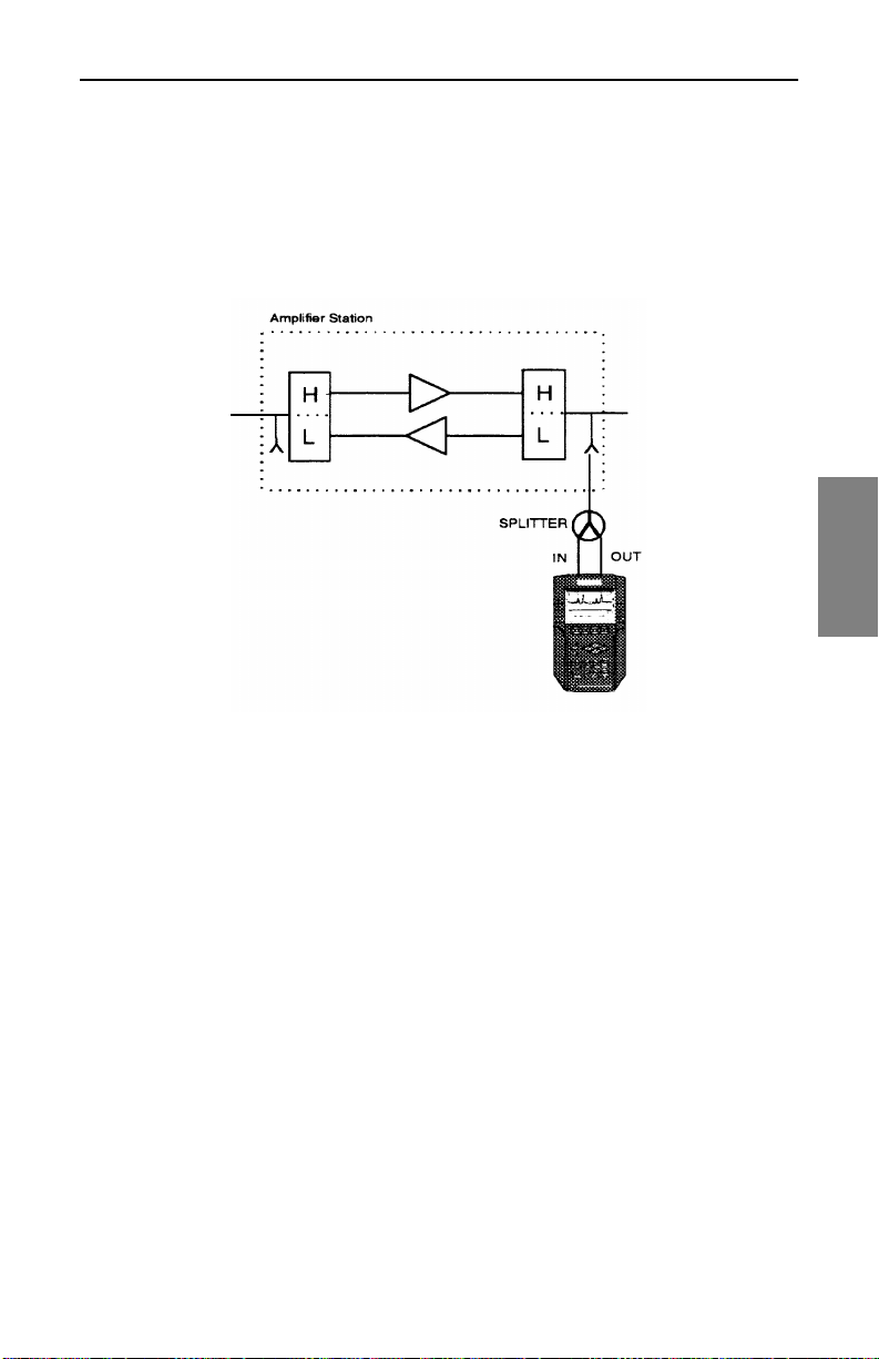
Field Sweeping with the SDA-5000: Considerations for Sweep in the Field
problem, but an artifact of the type of test point used and impedance
mismatches in the network.
If the video carriers at the forwar d test point are ab ove +2 0dBmV, then use a
pad to drop the levels. (Typically this will be the case only when there are
direct connections to an amplifier output.)
4
Fig. 4-7 SDA-5000 Connection in a Network with One Bi-directional Test
Point
• Dual cable networks: Dual cable networks are a second type of
forward/reverse network . Although thi s is a less co mmon con figuration , it
can also be swept in both directions.
Two s epa rate piec es of co ax are run to al l poin ts in the network . One is u sed
for forward path signals, the other for reverse path signals. This type of
network is more expensive to build, but it offers more return bandwidth.
Two cables can be used to sweep this typ e of sy s tem in bot h dire cti ons w ith
the same setup. A sample setup is shown in Fig. 4-9.
73
Page 98
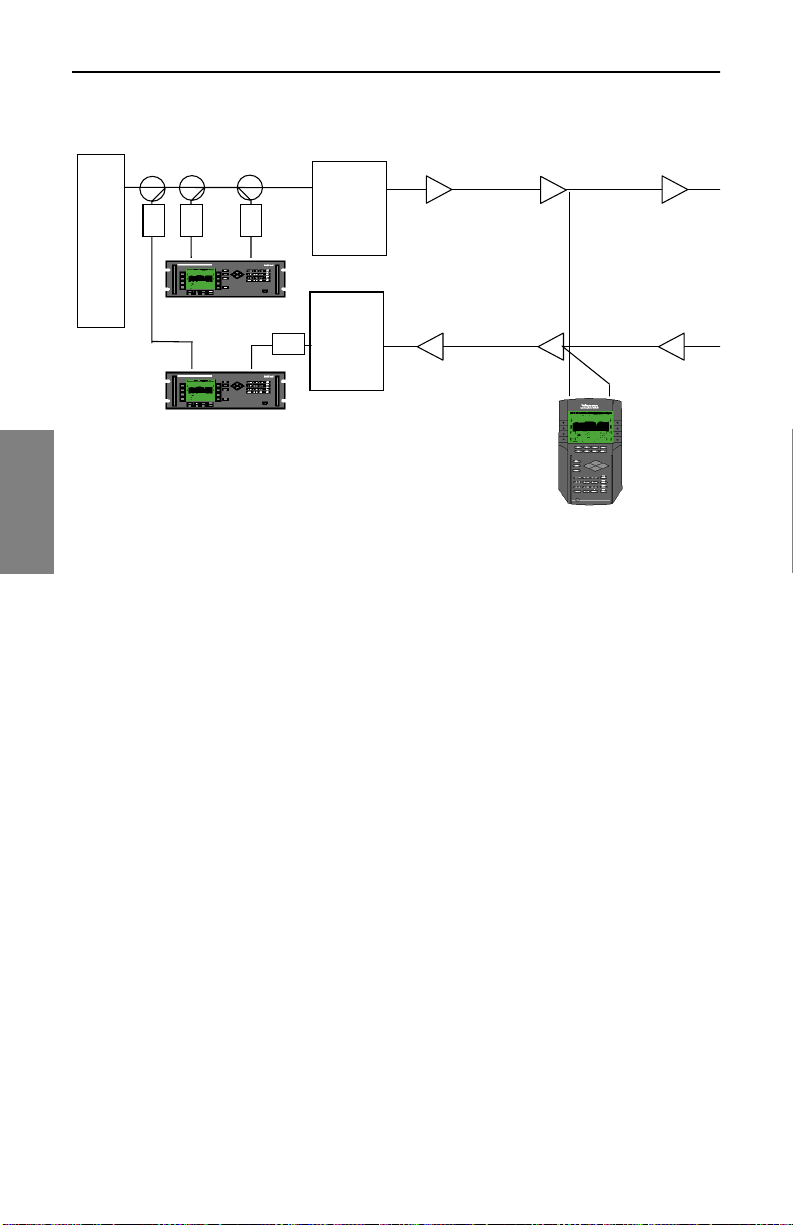
Field Sweeping wit h the SDA-5000: Co nsiderations for Sw eep in the Field
Forward Path Lines
TP
PAD
OUT
PAD
PAD
IN
Amps
Distribution
Lasers or
Combining Network
Note:
Pads may be omitted if not requ ired
for proper levels.
4
Reverse path ALC must be turned off.
SDA-5500
OUT IN
SDA-5510
The same information a bout le vels a nd direc tiona l test po int s appl y to a dua l
cable network as to a split band network.
Sweep Setup
Before you attempt a sweep in the field, configure and check the settings
described in this section.
1. Call up the CONFIGURE menu (use either the Navigator or the
Configure (Function and 3 ghi) key on the keypad) and select
SWEEP from the list.
Reverse Path Lines
PAD
or
Combiners
Optical Rcvr
SDA-5000
IN
Fig. 4-9 Dual Cable Network Test Setup
TP
OUT
2. At the SWEEP menu, use the arrow keys to select Stealth mode if it is
not already selected. (Stealth will appear in the Edit Box when it’s
selected.)
3. Forward Telemetry Frequency: Use the up and down dia mond keys or
the numeric keypad to enter the forward telemetry frequency
corresponding to that of the headen d unit .
4. If you’re using reverse sweep (SDA-5000 OPT1), you need to
configure the following additional settings:
74
Page 99

Field Sweeping with the SDA-5000: Considerations for Sweep in the Field
Reverse Sweep Operation:
• Select Single User for operation with an SDA-5500.
• Select Multiple Users for operation with an SDA-5510.
Reverse Telemetry Level:
This should be calculated by the system engineer and set before you start
sweep testing. This value is the system level for telemetry signals after test
point connection l os ses. R ev erse tes t point compensation can th en be used
to create the correct input levels for various amplifiers and test points.
Reverse Sweep Insertion Level:
This value should also be calculated by the system engineer and set before
you begin sweep testing. It is the required input level to the amplifier for
reverse sweep signals. Generally, reverse telemetry and reverse sweep
levels will be the same. Reverse test point compensation can then be used
to create the correct input levels for various amplifiers and test points.
See Also
½ “Reverse Injection Levels” (page 83) and “Test Point
Compensation Configura tion” (page 60) provide more
information.
4
NOTE: The information in the fo llowing secti ons rega rding
sweep operation is valid for both Stealth and SDA
Compatible Stealth sweeping.
However, keep in mind that for SDA Compatible Stealth
sweep to work, you must be using SDA equipment in both
the headend (SDA-550 0 a nd/or SDA-5510) and in the fi eld
(SDA-5000).
Forward Sweep Operation
You can get to the SWEEP screen (see Fig. 4-10) through the NAVIGATOR
or by pressing the SWEEP mea surement mode k ey under lowe r right corn er
of the screen.
This screen provides the following information (numbers correspond to
figure callouts:
75
Page 100

Field Sweeping wit h the SDA-5000: Co nsiderations for Sw eep in the Field
1. The vertical light bar just above REF at the top of the graph blinks on
and off with each trace refresh.
2. The ref level in dB appears in the left top of the graph.
3. The scale in dB/div appears next to the ref level in the middle top of
the graph.
4. The upper right corner identifies the kind of sweep: FWD or REV;
STEALTH, SDA STEALTH, or SWEEPLESS.
5. Horizontal markers enclose the min/max vertical deflection of the
sweep trace. You can choose to display them from the SWEEP menu
(see “Sweep Menu Options” on page 67).
6. You can move the vertical markers with the arrows along both sides,
or you can activate the marker and type in the frequency, then press
Enter.
7. The title of the current sweep reference is at the lower right corner. If
4
there is no current reference, this entry reads None.
8-9. The numbers at the A and B lines are the frequency positions of the
two vertical markers, followed by their relative levels in dB and the
difference between those levels.
Soft Key Icons:
10. Calls up the LEVEL submenu
11. Calls up the FREQ submenu
12. Calls up the LIMIT submenu
13. Calls up the TILT submenu
76
 Loading...