

ACT CT1999-FP, CT1999 Datasheet
CT1999
Remote Terminal and/or Bus Controller
for MIL-STD-1553B
Features
• Performs the Complete Dual-Redundant Remote Terminal and Bus Controller Protocol
Functions of MIL-STD-1553B
• Automatic Switchover to Superseding Input Commands
• MIL-PRF-38534 Compliant Circuits Available
• 750 mw Typical Power Consumption
• Small Size
• Available in Plug-in or Flatpack Configuration
• Compatible with all ACT Driver/Receiver Units
• 5V DC Operation
• Direct replacement for CT1602
• Full Military (-55°C to +125°C) Temperature Range
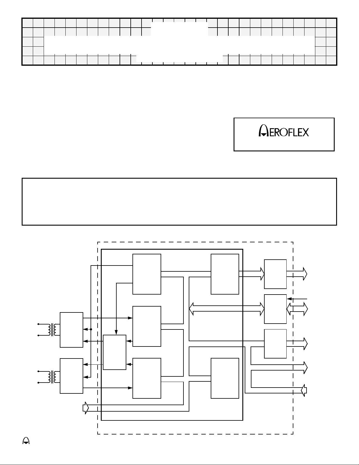
General Description
The CT1999 design incorporates ASIC and five Octal Buffers that accomplish the dual redundant
MIL-STD1553B Remote Terminal and/or Bus Controller Protocol Functions. Buffering has been added to the
most commonly used output signals on the CT1999, minimizing external hardware requirements. The CT1999
connects directly to all ACT Driver/Receiver Units.
CIRCUIT TECHNOLOGY
www.aeroflex.com
BUS "0"
BUS "1"
T/R
Hybrid
T/R
Hybrid
Term ina l
Address
Inputs
Block Diagram (With Transformer)
Encoder
Decoder
"O"
Driver
Select
&
Enable
Decoder
"1"
Interface
Unit
Internal
Highway
Control
ASIC
SA & WC
Buffers
Internal
Highway
Buffer
Discrete
Output
Buffers
Sub Address
&
Word Count
Outputs
Control
Data I/O
Buffered
Descrete
Outpu ts
Unbuffered
Outputs
Control
Inputs
eroflex Circuit T
echnology
CT1999
– Data Bus Modules For The Future SCDCT1999 REV B 8/14/01
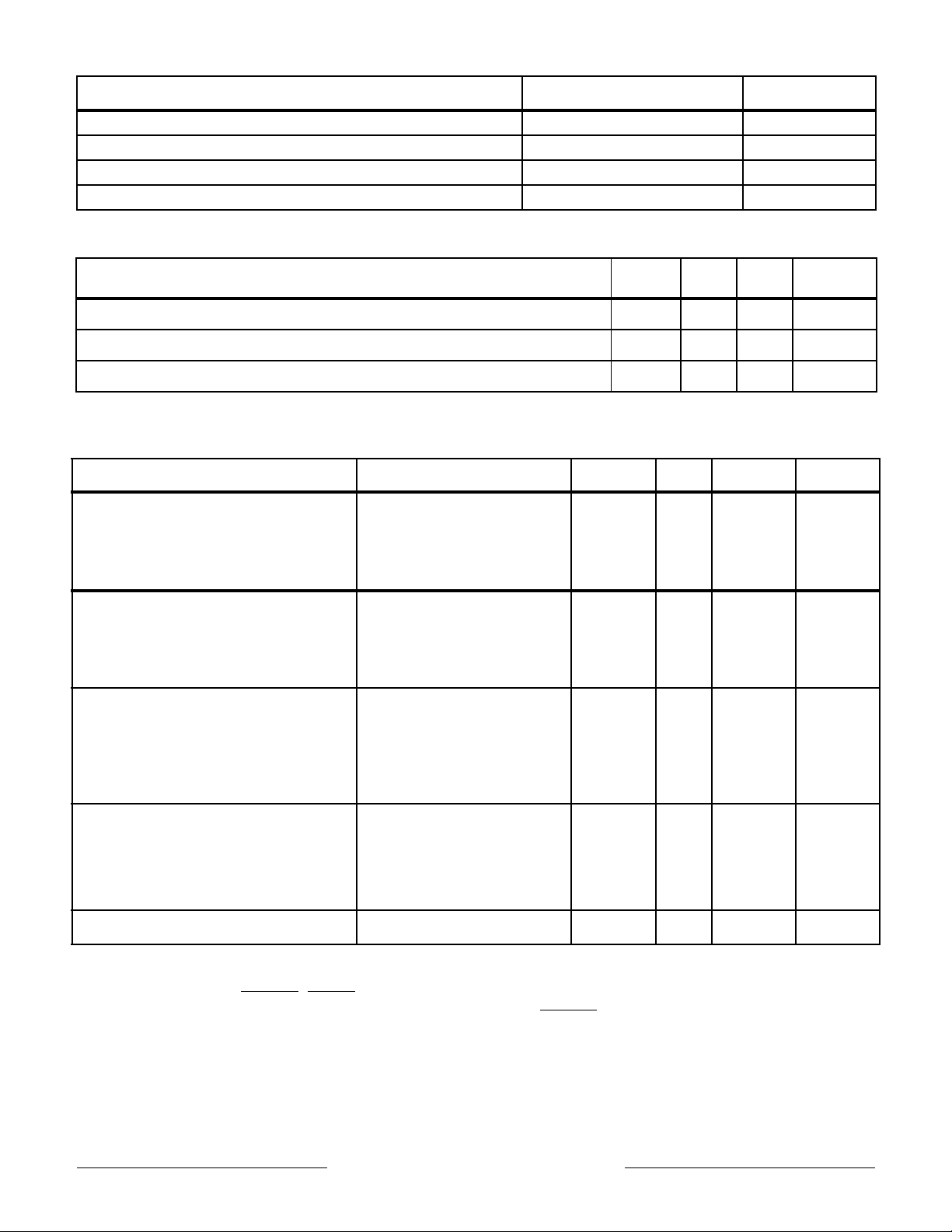
Absolute Maximum Ratings
Parameter Range Units
Operating Free-air Temperature -55°C to +125 °C
Storage Case Temperature -65°C to +150 °C
Power Supply Voltage V
CC
Input Voltage +7 Volts
+7 Volts
Recommended Operating Conditions
Parameter Min Typ Max Unit
VCC Power Supply Voltage V
V
High Level Input Voltage, Vcc = 5V
IH
Low Level Input Voltage, Vcc = 5V
V
IL
CC
4.5
2.2
5.0 5.5
0.7 V
V
V
Electrical Characteristics
(TA = -55°C to +125°C)
Parameter Test Conditions Min Max Unit Notes
= -400µA
= -800µA
= 4.5V
CC
= +4
= +2
= 4.5V
CC
mA
mA
mA
mA
V
High Level Output Voltage IOH = -3
OH
I
OH
I
OH
V
Low Level Output Voltage IOL = +12
V
OL
I
OL
I
OL
V
High Level Input Current VCC = 5.5V, VIH = 2.4V
I
IH
2.4
2.4
2.4
-700
-20
-700
-400
0.4
0.4
0.4
-200
20
-200
-25
V
V
V
V
V
V
µA
µA
µA
µA
2B,5
6
7
2B,5
6
7
1
2A,2B
3
4
Low Level Input Current
I
IL
Supply Current
I
CC
= 5.5V, VIL = 0.4V
V
CC
V
= 5.5V
CC
-900
-200
-900
-500
-350
0
-350
-25
µA
µA
µA
µA
285 mA
1
2A,2B
3
4
Notes (Pin numbers are for 90 pin Plug in package):
1. Pins 45 through 50 (RTADPAR,RTAD0,1,2,3,4). 2A. Pin 34 (IHDIR). 2B. Pins 37 through 44 (IH08 through
IH715). 3. Pins 24,36 (BUFINH
Buffered Outputs). 6. Pins 68,69,70,71 (TXINH0,TXINH1,TXDATA,TXDATA
, IHENA). 4. ALL remaining inputs ALL versions. 5. Pins 2 through 23 (Remaining
). 7. All remaining outputs.
Clock Requirements
Frequency
Stability (-55°C to +125°C)
Maximum Asymmetry
Rise/Fall Time
Aeroflex Circuit Technology SCDCT1999 REV B 8/14/01 Plainview NY (516) 694-6700
6MHz
±0.01%
48 - 52%
10ns MAX
2

REMOTE TERMINAL OPERATION
Receive Data Operation
All valid data words associated with a valid receive data command word for the RT are passed to the subsystem. The
RT examines all command words from the bus and will respond to valid (i.e. correct Manchester, parity coding etc.)
commands which have the correct RT address (or broadcast address if the RT broadcast option is enabled). When the
data words are received, they are decoded and checked by the RT and, if valid, passed to the subsystem on a word by
word basis at 20 µs intervals. This applies to receive data words in both Bus Controller to RT and RT to RT messages.
When the RT detects that the message has finished, it checks that the correct number of words have been received
and if the message is fully valid, then a Good Block Received signal is sent to the subsystem, which must be used by
the subsystem as permission to use the data just received.
The subsystem must therefore have a temporary buffer store up to 32 words long into which these data words can be
placed. The Good Block Received signal will allow use of the buffer store data once the message has been validated.
If a block of data is not validated, then Good Block Received will not be generated. This may be caused by any sort of
message error or by a new valid command for the RT being received on another bus to which the RT must switch.
Transmit Data Operation
If the RT receives a valid transmit data command addressed to the RT, then the RT will request the data words from the
subsystem for transmission on a word by word basis. To allow maximum time for the subsystem to collect each data
word, the next word is requested by the RT as soon as the transmission of the current word has commenced.
It is essential that the subsystem should provide all the data words requested by the RT once a transmit sequence has
been accepted. Failure to do so will be classed by the RT as a subsystem failure and reported as such to the Bus
Controller.
Control of Data Transfers
This section describes the detailed operation of the data transfer mechanism between RT and subsystems. It covers
the operations of the signals DTRQ
transfers.
Figure 7 shows the operation of the data handshaking signals during a receive command with two data words. When
the RT has fully checked the command word, NBGT
initialization signal. TX/RX
validated, DTRQ
indicates to the RT that the subsystem is ready to accept data The data word is then passed to the subsystem on the
internal highway IH08-IH715 in two bytes using IUSTB as a strobe signal and H/L as the byte indicator (high byte first
followed by low byte). Data is valid about both edges of IUSTB. Signal timing for this handshaking is shown in Figure
12.
If the subsystem does not declare itself busy, then it must respond to DTRQ
approximately 1.5 us. Failure to do so will be classed by the RT as a subsystem failure and reported as such to the Bus
Controller.
It should be noted that IUSTB is also used for internal working in the RT. DTRQ
for clocking data to the subsystem with IUSTB.
Once the receive data block has finished and been checked by the RT, GBR
and valid. This is used by the subsystem as permission to make use of the data block If no GBR signal is generated,
then an error has been detected by the RT and the entire data block is invalid and no data words in it may be used.
If the RT is receiving data in an RT to RT transfer, the data handshaking signals will operate in an identical fashion but
there will be a delay of approx 70 µs between NBGT
Figure 6 shows the operation of the data handshaking signals during transmit command with three, data words. As with
the receive command discussed previously, NBGT
set high indicating a transmit data command. While the RT is transmitting its status word, it requests the first data word
from the subsystem by setting DTRQ
DTAK
low. By setting DTAK low, the subsystem is indicating that it has the data word ready to pass to the RT. Once
DTAK
is set low by the subsystem, DTRQ should be used together with H/L and TX/RX to enable first the high byte and
then the low byte of the data word onto the internal highway IH08-IH715. The RT will latch the data bytes during IUSTB,
and will then return DTRQ
this handshaking is shown in Figure 11.
is set low. The subsystem must then reply within approximately 1.5 µs by setting DTAK low. This
will be set low indicating a receive command. When the first data word has been fully
high. Data for each byte must remain stable until IUSTB has returned low. Signal timing for
, DTAK, IUSTB, H/L, GBR, NBGT, TX/RX during receive data and transmit data
is pulsed low, which can be used by the subsystem as an
going low by setting DTAK low within
being low should be used as an enable
is pulsed low if the block is entirely correct
going low and DTRQ first going low. See Figure 10.
is pulsed low if the command is valid and for the RT. TX/RX will be
low. The subsystem must then reply within approximately 13.5 µs by setting
Aeroflex Circuit Technology SCDCT1999 REV B 8/14/01 Plainview NY (516) 694-6700
3

Additional Data Information Signals
At the same time as data transfers take place, a number of information signals are made available to the subsystem.
These are INCMD
Use of these signals is optional.
INCMD
and word count from the command word are all ma a vailable to the subsystem as SA0-4, TX/RX and WC0-4
respectively. They may be sampled when INCMD
The subaddress is intended to be used by the subsystem as an address pointer for the data block Subaddress 0 and
31 are mode commands, and there can be no receive or transmit data blocks associated with these. (Any data word
associated with a mode command uses different handshaking operations. If the subsystem does not use all the
subaddresses available, then some of the subaddress lines may be ignored.
The TX/RX
the previous section.
The word count tells the subsystem the number of words to expect to receive or transmit in a message, up to 32 words.
A word count of all 0s indicates a count of 32 words.
The current word count is set to 0 at the beginning of a new message and is incremented following each data word
transfer across the RT - subsystem interface. (It is clocked on the falling edge of the second IUSTB pulse in each word
transfer). It should be noted that there is no need for the subsystem to compare the word count and current word count
to validate the number of words in a message. This is done by the RT.
will go active low while the RT is servicing a valid command for the RT. The subaddress, transmit/receive bit.
signal indicates the direction of data transfer across the RT - subsystem interface. Its use is described in
, the subaddress lines SA0-4, the word count lines WC0-4 and current word count lines CWC0-4.
goes low and will remain valid while INCMD is low.
Subsystem Use of Status Bits and Mode Commands
General Description
Use of the status bits and the mode commands is one of the most confusing aspects of MIL-STD-1553B. This is
because much of their use is optional, and also because some involve only the RT while others involve both the RT and
the subsystem.
The CT1999 allows full use to be made of all the status bits, and also implements all the mode commands. The
subsystem is given the opportunity to make use of status bits, and is only involved in mode commands which have a
direct impact on the subsystem.
The mode commands in which the subsystem may be involved are Synchronize, Sychronize with data word, Transmit
Vector Word, Reset and Dynamic Bus Control Allocation. The status bits to which the subsystem has access are
Service Request, Busy, Subsystem Flag and Dynamic Bus Control Acceptance. Operation of each of these mode
commands and of the status bits is described in the following sections.
The subsystem designer should note that all other mode commands and status bits are serviced internally by the RT,
and the subsystem has no access to them. In particular, the terminal flag and message error status bits and BIT word
contents are all controlled internally by the RT.
Synchronize Mode Commands
Once the RT has validated the command word and checked for the correct address, the SYNC line is set low. The
signal WC4 will be set low for a Synchronize mode command Figure 16, and high for a Synchronize with data word
mode command Figure 15. In a Synchronize with data word mode command, SYNC
the data word is received. Once the data word has been validated, it is passed to the subsystem on the internal
highway IH08-IH715 in two bytes using IUSTB as a strobe signal and H/L as the byte indicator (high byte first followed
by low byte). SYNC
subsystem.
If the subsystem does not need to implement either of these mode commands, the SYNC
the RT requires no response from the subsystem.
being low should be used on the enable to allow IUSTB to clock synchronize mode data to the
remains low during the time that
signal can be ignored, since
Transmit Vector Word Mode Command
Figure 14 illustrates the relevant signal timings for an RT receiving a valid Transmit Vector Word mode command. The
RT requests data by setting VECTEN
byte of the Vector word onto the internal highway IH08-IH715.
It should be noted that the RT expects the Vector word contents to be already prepared in a latch ready for enabling
onto the internal highway when VECTEN
Aeroflex Circuit Technology SCDCT1999 REV B 8/14/01 Plainview NY (516) 694-6700
low. The subsystem should use H/L to enable first the high byte and then the low
goes low. If the subsystem has not been designed to handle the Vector word
4

mode command, it will be the fault of the Bus Controller if the RT receives such a command. Since the subsystem is
not required to acknowledge the mode command, the RT will not be affected in any way by Vector word circuitry not
being implemented in the subsystem. It will however transmit a data word as the Vector word, but this word will have
no meaning.
Reset Mode Command
Figure 8 shows the relevant signal timings for an RT receiving a valid reset mode command. Once the command
word has been fully validated and serviced, the RESET
function for subsystem interface circuitry.
signal is pulsed low. This signal may be used as a reset
Dynamic Bus Allocation
This mode command is intended for use with a terminal which has the capability of configuring itself into a bus
controller on command from the bus. The line DBCREQ
of the valid command, i.e. tied low. For terminals acting only as RTs, the signal DBCACC
(inactive), and the signal DBCREQ
should be ignored and left unconnected.
cannot go true unless the DBCACC line was true at the time
should be tied high
Use of the Busy Status Bit
The Busy Bit is used by the subsystem to indicate that it is not ready to handle data transfers either to or from the RT.
The RT sets the bit to logic one if the BUSY
edge of INCLK after INCMD
and transmit data word transfers to and from the subsystem. The data transfers in the Synchronize with data word
and Transmit Vector word mode commands are not affected by the Busy bit and will take place even if it has been set.
It should be noted that a minimum of 0.5 µs subaddress decoding time is given to the subsystem before sending of
status bits. This allows the subsystem to selectively set the Busy bit if for instance one subaddress is busy but others
are ready. This option will prove useful when an RT is interfacing with multiple subsystems.
goes low. This is shown in Figure 13. Once the Busy bit is set, the RT will stop all receive
line from the subsystem is active low at the time of the second falling
Use of the Service Request Status Bit
The Service Request bit is used by the subsystem to indicate to the Bus Controller that an asynchronous service is
requested.
The timing of the setting of this bit is the same as the Busy bit and is shown in Figure 13. Use of SERVREQ
effect on the RT apart from sening the Service Request bit.
It should be noted that certain mode commands require that the last status word be transmitted by the RT instead of
the current one, and therefore a currently set status bit will not be seen by the Bus Controller. Therefore the user is
advised to hold SERVREQ
low until the requested service takes place.
has no
Use of the Subsystem Status Bit
This status bit is used by the RT to indicate a subsystem fault condition. If the subsystem sets SSERR low at any
time, the subsystem fault condition in the RT will be set, and the Subsystem Flag status bit will subsequently be set
The fault condition will also be set if a handshaking failure takes place during a data transfer to or from the
subsystem. The fault condition is cleared on power-up or by a Reset mode command.
Dynamic Bus Control Acceptance Status Bit
DBCACC, when set true, enables an RT to configure itself into a Bus Controller, if the subsystem has the capability,
by allowing DBCREQ
required then DBCACC
response.
to pulse true and BIT TIME 18 to be set in the status response. If Dynamic Bus Control is not
must be tied high. DBCACC tied high inhibits DBCREQ and clears BIT TIME 18 in the status
Bus Driver/Receiver Interface
Receive Data
The decoder chip requires two TTL signals (PDIN & NDIN) to represent the data coming in from the bus. PDIN should
be driven to a logic level ‘1’ when the bus waveform exceeds a specified positive threshold and NDIN should be
driven to a logic level ‘1’ when a specified negative threshold is exceeded. During the quiet period on the bus both
signals should be at the same logic level. All the bus receivers must be permanently enabled, the selection if the bus
in use is done within the ASIC.
Aeroflex Circuit Technology SCDCT1999 REV B 8/14/01 Plainview NY (516) 694-6700
5

Transmit Data
The signals generated by the encoder chip (PDOUT & NDOUT) are of the same format as the receive data The only
difference is that the TTL signals are negative logic, e.g. the signal is active when on logic level "0". This means that
when the encoder is quiet both PDOUT
with TXEN
should be transmitting, and the driver enable routes the data on to the bus in use.
Figure 5 shows an example of a typical interface circuit between the CT1999 and a driver/receiver unit.
and the appropriate driver enable, e.g. (CS0 - enable for bus 0). TXEN only enables the driver when it
& NDOUT are at logic level ‘1’. Both the signals should be used in conjunction
BUS CONTROL OPERATION
To enable its use in a bus controller each chip in the chipset has additional logic within it. This logic can be enabled by
pulling the pin labelled RT/BC
bus control processor correctly commanding the chipset via the subsystem interface. In bus control mode six inputs are
activated which in RT mode are inoperative and four signals with dual functions exercise the second function (the first
being for the RT operation).
To use the CT1999 as a 1553B bus control interface, the bus control processor must be able to carry out four basic
bus-related functions. Two inputs, BCOPA and BCOPB allow these four options to be selected. The option is then
initiated by sending a negative-going strobe on the BCOPSTB input. BCOPSTB
is high. This is particularly important when two options are required during a single transfer.
With these options all message types and lengths can be handled. Normal BC/RT exchanges are carried out in the
chipset option zero. This is selected by setting BCOPA and BCOPB to a zero and strobing BCOPSTB
strobe, the CT1999 loads the command word from an external latch using CWEN and H/L The command word is
transmitted down the bus. The TX/RX
command is sent to a RT, Figure 17, the chipset in BC mode believes it has been given a receive command. As the RT
returns the requested number of data words plus its status, the BC chipset carries out a full validation check and
passes the data into the subsystem using DTRQ
GBR
at the end of a valid transmission. Conversely, a receive command sent down the bus is interpreted by the BC
chipset as a transmit command, and so the requisite data words are added to the command word, see Figure 18.
For mode commands, where a single command word is required, option one is selected by strobing BCOPSTB
BCOPA is high and BCOPB is low. On receiving the strobe, the command word is loaded from the external latch using
CWEN
followed by a data word requires option two. Option two, selected by strobing BCOPSTB
BCOPB is high, loads a data word via DWEN
21. If the mode code transmitted required the RT to return a data word, then selecting option three by strobing
BCOPSTB
subsystem interface using RMDSTB and H/L
differently from ordinary data words and routed accordingly, see Figure 22. All received status words are output to the
subsystem interface using STATSTB and H/L
In BC option three, if the signal PASMON
subsystem using STATSTB for command and status words or RMDSTB for data words.
RT to RT transfers require the transmission of two command words. A receive command to one RT is contiguously
followed by a transmit command to the the other RT. This can be achieved by selecting option one followed by option
zero for the second command. The strobe (BCOPSTB
returned high following the strobe for option one. The RT transmissions are checked and transferred in the subsystem
interface to the bus control processor, see Figure 19.
Note: For all BC operations, BCOPA and BCOPB must remain valid and stable for a minimum of 1 µs following the
leading (negative going) edge of BCOPSTB
and H/L, the correct sync and parity bits are added and the word transmitted, see Figure 20. Mode commands
when BCOPA and BCOPB are both high will identify that data word and if validated, output it to the
low. Once the chipset is in bus control mode, all data transfers must be initiated by the
must only be strobed low when NDRQ
. On receipt of the
bit is, however, considered by the chipset as being its inverse and so if a transmit
, DTAK, H/L, IUSTB and CWC as in RT operation. It also supplies
when
while BCOPA is low and
and H/L, adds sync and parity and transmits them to the bus, see Figure
This allows data words resulting from mode codes to be identified
.
is active, then all data appearing on the selected bus is output to the
) for option zero must be delayed until NDRQ has gone low and
.
Aeroflex Circuit Technology SCDCT1999 REV B 8/14/01 Plainview NY (516) 694-6700
6

Pin Description
Signal
RX DATA 0/1 SINK Positive Date In. This should be a TTL description of the positive, half of the
RX DATA
TX INHIBIT 0/1 SOURCE Transmitter Enable. Goes low when the transmitter is transmitting. Should be
TX DATA SOURCE Positive Data Out - When this signal goes high the bus should be driven
TX DATA
RTAD 0-4 SINK RT address lines - These should be hardwired by the user. RTAD4 is the most
RTADPAR SINK RT address parity line - This must be hardwired by the user to give odd parity.
BCSTEN 0/1 SINK Recognition of Broadcast command enable - When low the recognition of
6MCK SINK 6 Megahertz master clock.
0/1 SINK Negative Data In. This should be a TTL description of the negative half of the
Hybrid
Sink or Source
Manchester code data on the bus. It should be driven to a logic level “1” when
a predetermined positive threshold is exceeded on the bus.
Manchester code data on the bus. It should be driven to a logic level “1” when
a predetermined negative threshold is exceeded on the bus.
used to enable the bus drivers.
positive.
SOURCE Negative Data Out - When this signal goes high the bus should be driven
negative.
significant bit.
broadcast command is prevented on the specified bus.
Signal Description
IH 08
IH 19
IH 210
IH 311
IH 412
IH 513
IH614
IH715
DTRQ
DTAK
IUSTB SOURCE Interface Unit Strobe - This is a double pulse strobe used to transfer the two
H/L
GBR
NBGT
TX/RX
SINK/SOURCE Internal Highway - Bi-directional 8 bit highway on which 16 bit words are
passed in two bytes. IH 715 is the most significant bit of each byte, the most
significant byte being transferred first. The highway should only be driven by
the subsystem when data is to be transferred to the RT.
SOURCE Data Transfer Request - Goes low to request a data transfer between the
ASIC and subsystem. Goes high at the end of the transfer.
SINK Data Transfer Acknowledge - Goes low to indicate that the subsystem is
ready for the data transfer.
bytes of data
SOURCE High/Low - Indicates which byte of data is on the internal highway. Logic level
"0" for least significant byte.
SOURCE Good Block Received - Pulses low for 500ns when a block of data has been
received by the ASIC and has passed all the validity and error checks.
SOURCE New Bus Grant - Pulses low whenever a new command is accepted by the
ASIC.
SOURCE Transmit/Receive - The state of this line informs the subsystem whether it is
to transmit or receive data The signal is valid while INCMD
is low.
INCMD
WC 0-4 SOURCE Word Count - These five lines specify the requested number of data words to
Aeroflex Circuit Technology SCDCT1999 REV B 8/14/01 Plainview NY (516) 694-6700
SOURCE In Command - Goes low when the RT is servicing a valid command. The
subaddress and word count lines are valid while the signal is low.
be received or transmitted. Valid when INCMD
7
is low.

Pin Description (Cont.)
Signal
SA 0-4 SOURCE Sub Address - These five lines are a label for the data being transferred. Valid
CWC 0-4 SOURCE Current Word Count - These five lines define which data word in the message
SYNC
VECTEN
RESET
SSERR
BUSY
SERVREQ
/DWEN SOURCE Vector Word Enable/DataWord Enable - In the RT mode, this signal is
Hybrid
Sink or Source
when INCMD is low.
is currently being transferred.
SOURCE Synchronize - Goes low when a synchronize mode code is being serviced.
provided to enable the contents of the vector word latch (which is situated in
the subsystem) onto the ASIC’s internal highway. This signal, when in the Bus
Controller mode, is used to enable mode code data from the subsystem onto
the internal highway.
SOURCE Reset - This line pulses low for 500ns on completion of the servicing of a valid
and legal mode command to reset remote terminal.
SINK Subsystem Error - By taking this line low, the subsystem can set the
Subsystem Flag in the Status Word.
SINK Busy - This signal should be driven low if the subsystem is not ready to
perform a data transfer to or from the ASIC.
SINK Service Request - This signal should be driven low to request an
asynchronous transfer and left low until the transfer has taken place.
Signal Description
INCLK SOURCE Internal Clock (2 MHz) - This is made available for synchronization use by the
subsystem if required. However, many of the outputs to the subsystem are
asynchronous.
EOT
RTADER
HSFAIL
LSTCMD
STATEN
STATSTB
/
BITEN
RMDSTB
/CWEN SOURCE Last Command/Command Word Enable - This line pulses low when
/
SOURCE End of Transmission - Goes low if a valid sync plus two data bits do not
appear in time to be contiguous with preceding word.
SOURCE Remote Terminal Address Error - This line goes low if an error is detected in
the RT address parity of the selected receiver. Any receiver detecting an error
in the RT address will turn itself off.
SOURCE Handshake Failure - This line pulses low if the allowable time for DTAK
response has been exceeded during the ASIC/subsystem data transfer
handshaking.
servicing a valid and legal mode command to transmit last command. When in
RT mode this line must not be used to enable data from the subsystem. This
line also pulses low, when in the Bus Control mode, when a command word is
required for transmission.
SOURCE Status Enable/Status Strobe - This line pulses low to enable the status word
onto the internal highway for transmission. When in RT mode this line must not
be used to enable data from the subsystem. This line also pulses high, when in
the Bus Control mode, to strobe received status words into the subsystem.
When PASMON
SOURCE Built In Test Enable/Receive Mode Data Strobe - This line pulses low when
servicing a valid and legal mode command to transmit the internal BIT word.
This signal is for information only and must not be used to enable data from the
subsystem. This line also pulses high when in the Bus Control mode when
mode data is received to be passed to the subsystem and when data is passed
to the subsystem during PASMON
is true this line pulses high for Command and Status words.
.
DWSYNC
Aeroflex Circuit Technology SCDCT1999 REV B 8/14/01 Plainview NY (516) 694-6700
SOURCE Data Word Sync - This line goes low if a data word sync and two Manchester
biphase bits are valid.
8
 Loading...