

Page 1

Central Filter Systems
XFC-S Series
Effective: 10/05
Bulletin #: CV2-600
Part #: 882.00091.00
1
Page 2

800 Wood Dale Drive
Wood Dale, IL 60191
Telephone: (630) 595-1060
Fax: (630) 595-8924
www.acscorporate.com
Technical Service:
Service department
Telephone: (800) 423-3183
These operating instructions are for*:
(* please fill in personally)
Serial number:
Year of manufacture:
ACS Group
Date of Delivery:
Number of delivery:
Date of commissioning:
Location:
Group of machines:
ACS retains all rights to change the information in these operating instructions at any time
without notice.
We assume no liability for any errors or direct or indirect damage resulting in context with these
operating instructions.
Copying, translation or publication in any form except for personal use of purchaser requires
approval from ACS.
All rights reserved.
2
Page 3

Please note that our address and phone information has changed.
Please reference this page for updated contact information.
These manuals are obsolete and are provided only for their technical information, data and capacities.
Portions of these manuals detailing procedures or precautions in the operation, inspection, maintenance
and repair of the products may be inadequate, inaccurate, and/or incomplete and shouldn’t be relied
upon. Please contact the ACS Group for more current information about these manuals and their
warnings and precautions.
Parts and Service Department
The ACS Customer Service Group will provide your company with genuine OEM quality parts manufactured to engineering
design specifications, which will maximize your equipment’s performance and efficiency. To assist in expediting your phone
or fax order, please have the model and serial number of your unit when you contact us. A customer replacement parts list
is included in this manual for your convenience. ACS welcomes inquiries on all your parts needs and is dedicated to
providing excellent customer service.
For immediate assistance, please contact:
• North, Central and South America, 8am – 5pm CST +1 (800) 483-3919 for drying, conveying, heating and cooling
and automation. For size reduction: +1 (800) 229-2919.
North America, emergencies after 5pm CST (847) 439-5855
North America email: acsuscanadacustserv@corpemail.com
• Mexico, Central & South America
Email: acslatinamericacustserv@corpemail.com
• Europe, Middle East & Africa +48 22 390 9720
Email: acseuropecustserv@corpemail.com
• India +91 21 35329112
Email: acsindiacustserv@corpemail.com
• Asia/Australia +86 512 8717 1919
Email: acsasiacustserv@corpemail.com
Sales and Contracting Department
Our products are sold by a worldwide network of independent sales representatives. Contact our Sales Department for the
name of the sales representative nearest you.
Let us install your system. The Contract Department offers any or all of these services: project planning; system packages
including drawings; equipment, labor, and construction materials; and union or non-union installations.
For assistance with your sales or system contracting needs please Call:
North, Central and South America +1 (262) 641-8600 or +1 (847) 273-7700 Monday–Friday, 8am–5pm CST
Europe/Middle East/Africa +48 22 390 9720
India +91 21 35329112
Asia/Australia +86 512 8717 1919
Facilities:
ACS offers facilities around the world to service you no matter where you are located. For more information, please visit us at
www.acscorporate.com
United States:
ACS Schaumburg – Corporate Offices
1100 E. Woodfield Road
Suite 588
Schaumburg, IL 60173
Phone: + 1 847 273 7700
Fax: + 1 847 273 7804
ACS New Berlin – Manufacturing Facility
2900 S. 160th Street
New Berlin, WI 53151
Phone : +1 262 641 8600
Fax: + 1 262 641 8653
Asia/Australia:
ACS Suzhou
109 Xingpu Road SIP
Suzhou, China 215126
Phone: + 86 8717 1919
Fax: +86 512 8717 1916
Europe/Middle East/Africa:
ACS Warsaw
Ul. Działkowa 115
02-234 Warszawa
Phone: + 48 22 390 9720
Fax: +48 22 390 9724
India
ACS India
Gat No. 191/1, Sandbhor Complex
Mhalunge, Chakan, Tal Khed,
Dist. Pune 410501, India
Phone: +91 21 35329112
Fax: + 91 20 40147576
Page 4

Shipping Information
Unpacking and Inspection
You should inspect your equipment for possible shipping damage. Thoroughly check the
equipment for any damage that might have occurred in transit, such as broken or loose wiring and
components, loose hardware and mounting screws, etc.
In the Event of Shipping Damage
According to the contract terms and conditions of the Carrier, the responsibility of the Shipper
ends at the time and place of shipment.
Notify the transportation company’s local agent if you discover damage
Hold the damaged goods and packing material for the examining agent’s inspection. Do not
return any goods before the transportation company’s inspection and authorization.
File a claim with the transportation company. Substantiate the claim by referring to the agent’s
report. A certified copy of our invoice is available upon request. The original Bill of Lading is
attached to our original invoice. If the shipment was prepaid, write us for a receipted
transportation bill.
Advise customer service regarding your wish for assistance and to obtain an RMA (return
material authorization) number.
If the Shipment is Not Complete
Check the packing list as back-ordered items are noted on the packing list. In addition to the
equipment itself, you should have:
• Bill of lading
• Packing list
• Operating and Installation packet
• Electrical schematic and panel layout drawings
• Component instruction manuals (if applicable)
Re-inspect the container and packing material to see if you missed any smaller items during
unpacking.
If the Shipment is Not Correct
If the shipment is not what you ordered, contact the shipping department immediately. For
shipments in the United States and Canada, call 1 (800) 233-4819; for all other countries, call our
international desk at (630) 475-7491. Have the order number and item number available.
Hold the items until you receive shipping instructions.
Returns
Do not return any damaged or incorrect items until you receive shipping instructions from the
shipping department.
3
Page 5

Warranty
We warrant all of our equipment to be free from defects in workmanship and material when
used under recommended conditions. The manufacturer’s obligation is limited to repair or
replace FOB the factory any parts that are returned prepaid within one year of equipment
shipment to the original purchaser, and which, in the manufacturer’s opinion, are defective.
Any replacement part assumes the unused portion of this warranty.
This warranty does not apply to any equipment which, in the manufacturer’s opinion, has
been subjected to misuse, negligence, or operation in excess of recommended limits or which
has been repaired or altered without the manufacturer’s express authorization. If the serial
number has been defaced or removed from the component, the warranty on that component is
void. Defective parts become the property of the warrantor and are to be returned.
The manufacturer is not liable for any incidental, consequential, or special damages or
expenses. The manufacturer’s obligation for parts not furnished as components of its
manufactured equipment is limited to the warranty of the manufacturers of said parts.
Any sales, use, excise, or other tax incident to the replacement of parts under this warranty is
the responsibility of the purchaser.
The manufacturer neither assumes nor authorizes any other persons to assume for it any
liability in connection with the sale of its equipment not expressed in this warranty.
Many types of the manufacturer’s equipment carry an additional one-year service policy.
Consult your sales representative for specific details.
4
Page 6

Table of Contents
1. General Instructions ................................................................................................ 7
1.1. Warnings and Symbols ......................................................................................................7
1.2. Explanations and Information............................................................................................. 8
2. Safety Instructions................................................................................................... 9
2.1. For Your Safety.................................................................................................................. 9
2.2. For the Operating Safety of the Equipment...................................................................... 12
3. Transport, Assembly and Storage........................................................................ 13
3.1. Transport and Packing.....................................................................................................13
3.2. Assembly .........................................................................................................................13
4. Assembly Instructions .......................................................................................... 14
4.1. Installation........................................................................................................................ 15
4.3. Electrical Connection ....................................................................................................... 17
4.4. Compressed Air Blowback Connection............................................................................ 19
4.5. Implosion Blowback Connection ...................................................................................... 20
5. Functional Description .......................................................................................... 21
6. Operation................................................................................................................ 23
6.1. Adjusting the Blowback Air Pulse Timing......................................................................... 23
6.2. Adjusting the Number of Air Pulses .................................................................................24
6.3. Starting Filter Chamber Operation ................................................................................... 24
7. Maintenance ........................................................................................................... 25
7.1. Maintenance Intervals......................................................................................................26
7.2. Servicing the Filter ........................................................................................................... 27
7.3 Cleaning the Collection Bin (All Models except XFC 225 and XFC 1000) ....................... 27
7.4 Cleaning the Filter Shroud (XFC 225 and XFC 1000)...................................................... 27
7.5 Cleaning/Replacing the Filter Cartridge ........................................................................... 28
7.6 Replacing the Gaskets (XFC-K/XFC-A Only)................................................................... 32
7.7 Replacing/Cleaning the Filter Cartridge of the Collection Bin Vent (XFC-K Only) ........... 34
7.8. Dismantling and Disposal................................................................................................ 35
8. Technical Data........................................................................................................ 36
9. Spare Parts Lists.................................................................................................... 41
9.1. Parts Breakdown, XFC-K................................................................................................. 42
9.2. Parts List, XFC-K ............................................................................................................. 43
9.3 Parts Breakdown, XFC-A................................................................................................. 45
9.4. Parts List, XFC-A ............................................................................................................. 45
9.5 Parts Breakdown, XFC-S................................................................................................ 47
9.6. Parts List, XFC-S ............................................................................................................ 47
9.7 XFC 225.......................................................................................................................... 49
9.8 XFC 1000........................................................................................................................ 49
5
Page 7

10. Troubleshooting..................................................................................................... 48
11. Technical Assistance ............................................................................................ 50
11.1. Parts Department........................................................................................................... 50
11.2. Service Department .......................................................................................................50
11.3. Sales Department ..........................................................................................................50
11.4. Contract Department...................................................................................................... 50
6
Page 8

1. General Instructions
These instructions apply to all persons who may operate the equipment.
These operating instructions are to be read and used by all persons assigned to use the
equipment. Ensure that all operating personnel are familiar with the operating
instructions.
1.1. Warnings and Symbols
The following warnings and symbols are used in these operating instructions:
This symbol indicates danger to life. Fatal or serious injury is possible if the
corresponding instructions, regulations or warnings are not observed.
This symbol indicates that serious injury is possible if the corresponding instructions,
regulations or warnings are not observed.
This symbol indicates that extensive damage to equipment is possible if the
corresponding instructions, regulations or warnings are not observed.
This symbol indicates information important for becoming familiar with the equipment,
i.e. technical correlations.
This symbol indicates that a technical term is explained at this point.
7
Page 9

1.2. Explanations and Information
Various terms are used in these operating instructions to ensure clarity. Therefore, please note
that the terms used in the text stand for the corresponding explanations listed below.
• Equipment: ”Equipment” can mean an individual unit, a machine or an installation.
• Operating personnel: The ”operating personnel” are persons operating the equipment on their
own responsibility or according to instructions.
• Operator: The ”operator” of the equipment (production manager, foreman, etc.) is the person
responsible for all production sequences. The operator instructs the operating personnel of
what is to be done.
• Operating instructions: The ”operating instructions” describe the interaction of the
equipment, production sequences or methods. The operating instructions must be compiled
by the operator of the equipment.
• Equipment foreman: When several operating personnel work on one machine, the
”equipment foreman” coordinates the sequences. The equipment foreman must be appointed
by the operator.
• Trained personnel: ”Trained personnel” are persons who, due to their training, are authorized
to carry out the required work.
8
Page 10

2. Safety Instructions
These safety instructions apply to all persons who may use the equipment, and should
be used by all persons assigned activities connected with the equipment.
Please inform all persons within the range of action of the equipment of the direct and
indirect hazards connected with the equipment.
Knowledge of the English language is prerequisite.
Ensure that all operating personnel are familiar with the operating instructions and the
function of the equipment.
2.1. For Your Safety
2.1.1. General
To prevent injury and/or damage to equipment, observe the following safety rules:
• Read these operating instructions carefully before operating for the first time. Contact us
should questions arise.
• These operating instructions must be kept available at all times at the place of operation of
the equipment.
• Please note that, for reasons of clarity, not all conceivable cases regarding operation or
maintenance of the equipment can be covered in these operating instructions.
• Observe all safety instructions and warnings on the equipment.
• All work on the equipment is to be carried out by persons whose qualifications are specified
in the pertaining chapters of the operating instructions.
• Wear proper working clothes while performing any work on the equipment.
• Observe all local regulations and requirements pertaining to this equipment
• Disconnect electrical components from the main power supply before work is carried out on
these components
• Compile detailed operating instructions based on these operating instructions for the sequence
of procedures to be carried out on this equipment.
• Please note that sound levels exceeding 85 db(A) may in the long term damage your health.
Use appropriate ear protection to prevent hearing impairment.
9
Page 11

2.1.2. Assembly
To prevent injury and/or damage to equipment, observe the following safety rules:
• Compare the connected loads with those of the main supply.
• Use care when using lifting gear, and observe any pertaining regulations.
• Do not modify, add other equipment or change the design of the equipment without the
approval of the manufacturer.
• Attachments not supplied by the manufacturer must be manufactured in accordance with
safety regulation EN 294.
• Make sure all the accessories and components are properly connected in accordance with any
relevant regulations.
• To prevent electrical shock, operate the device only if all its components are grounded.
• Do not allow solid particles and dust to enter to the vacuum pump.
10
Page 12

2.1.3. Operation
To prevent injury and/or damage to equipment, observe the following safety rules:
• Appoint an equipment foreman to be responsible for the equipment.
• Ensure that the operating personnel are provided detailed instruction in the operation of the
equipment.
• When the main switch is switched off for reasons pertaining to safety, it must be secured and
locked out to prevent injury.
• Repair work may be carried out by trained personnel only.
• Never operate the equipment when it is partially dismantled.
• In case of malfunction, shut down the equipment immediately. Repair the equipment
immediately.
• The equipment is intended only for conveying granulated plastics and regrinds. Any other or
additional use is contrary to specifications.
• This equipment is not suitable for food processing.
• The safety instructions of the connected machines must be followed.
2.1.4. Maintenance
To prevent injury and/or damage to equipment, observe the following safety rules:
• Before starting maintenance work, appoint a supervisor.
• Inform the responsible personnel before maintenance work on the system is started.
• Disconnect the equipment from main supply and ensure that it is locked out before starting
maintenance procedures to ensure that it cannot be switched on unintentionally.
• All pipes, hoses and threaded connections should be checked regularly for leaks and damage.
Any faults that arise should be corrected immediately.
• Depressurize all compressed air piping before starting maintenance work.
11
Page 13

2.2. For the Operating Safety of the Equipment
• Never change settings if the consequences are not precisely known.
• Use only original manufacturer-approved spare parts.
• Please observe the maintenance schedule.
• Keep a record of all maintenance and repair work.
• Please note that electronic components may be damaged by static discharge.
• Check all electrical connections for proper fit before the equipment is operated for the first time
and at regular intervals.
• Please note that the ambient temperature must not exceed 158ºF (70ºC).
• The central filter requires a compressed-air supply, max. 60-80 PSI (4.1-5.5 bar).
• Never use a higher operating pressure than 80 PSI (5.5 Bar).
• Install the central filter in the process suction line right in front of the vacuum pump.
• Make sure the filter-cleaning procedure is carried out while the vacuum pump is running.
• Follow the operating instructions of the conveying system.
• Check the dust container for tightness following each cleaning procedure.
• Follow the operating instructions of each connected machine.
• All components must be sufficiently grounded.
12
Page 14

3. Transport, Assembly and Storage
This chapter is intended for all operating personnel of the equipment.
Personnel using these instructions must be made aware of the regul5ations for the
prevention of accidents, the operating conditions and safety regulations and their
implementation.
Ensure in each case that the operating personnel are sufficiently informed.
Please inform all persons who may use the equipment of the direct and indirect hazards
associated with the equipment.
Please observe all safety regulations for the operation of lifting equipment.
3.1. Transport and Packing
Please ensure adequate carrying capacity of the lifting equipment.
The unit is delivered as a complete sub-assembly. Transport the unit on a pallet. Lift the unit only
by the mounting flanges on the side of the filter or by the filter chamber. Never lift the filter by
the solenoid or inlet tubes.
The equipment passes rigorous testing in the factory and is packed carefully to avoid transport
damage.
Please check packing on delivery for transport damage. Packing materials should be disposed of
according to environmental laws or reused.
Only use for transport of the equipment a suitable lifting device (e.g. a fork lift truck or a
workshop crane).
Transport must be shock-proofed and free from vibrations.
3.2. Assembly
Please ensure adequate carrying capacity of the lifting equipment.
Check the carrying capacity of the point of installation, particularly if installed on a
platform.
The place selected for installation should be as free of vibrations as possible.
The main power switch must be freely accessible.
Ground the equipment against electrostatic charging.
13
Page 15

4. Assembly Instructions
These installation instructions are intended for persons with skills in electrical and
mechanical areas due to their training, experience and received instructions.
Personnel using these installation instructions must be made aware of the regulations
for the prevention of accidents, the operating conditions and safety regulations and
their implementation.
Ensure in each case that the personnel are sufficiently knowledgeable about the
equipment.
The installation instructions provided in the corresponding operating instructions apply
for all connected equipment.
Please observe all safety regulations for the operation of lifting gear.
All installation work must be carried out with the equipment disconnected from
electrical power and compressed air supply.
For installation work taking place at heights of over approx. 6 feet, use only ladders or
similar equipment and working platforms intended for this purpose. At greater heights,
the proper equipment for protection against falling must be used.
Use only suitable lifting gear that is in proper working order and load suspension
devices with sufficient carrying capacity. Do not stand or work under suspended loads!
Use only suitable workshop equipment.
Install the equipment so that all parts are easily accessible; this facilitates maintenance
and repair work.
14
Page 16
4.1. Installation
Use the following procedure to install the safety filter:
1. Place the safety filter in the conveying system directly before the vacuum pump.
2. Using 7/16”, Grade 5 or better hardware, secure the filter in place:
Wall Mount. Use the mounting flange to secure the filter to the wall.
Floor Mount. Bolt the floor stand to the ground.
Pump Mount. Bolt the pump and stand to the ground. Pump-mount is only available with
XPC pumps.
Note: Floor leg kits are available to convert a standard wall mount configuration to a
floor mount configuration. Part No. A0570013. Two (2) required per assembly.
Make sure all screws are strong enough to hold the weight of the filter.
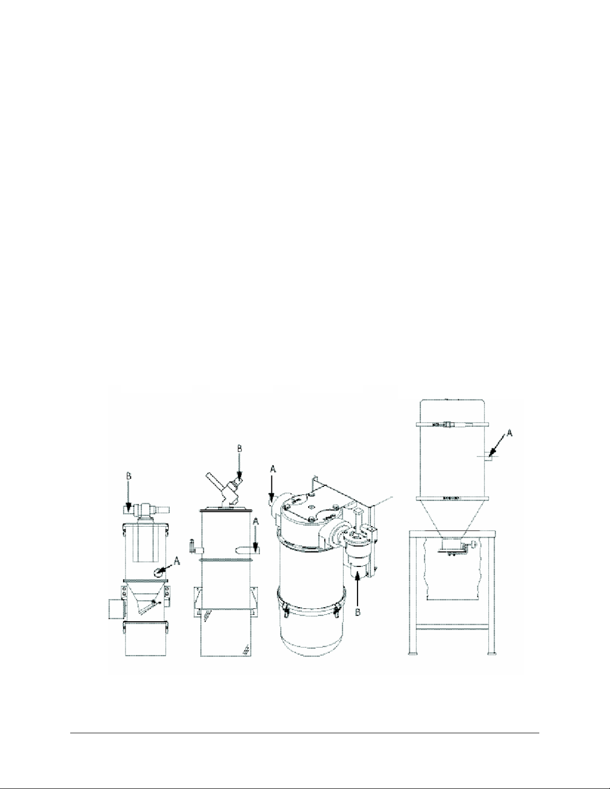
3. Connect the vacuum line to the filter chamber’s inlet tube (A). Use a hose clamp to secure the
flexible hose.
4. Connect the vacuum pump line to the outlet tube (B). Use a hose clamp to secure the flexible
hose.
XFC-K XFC-A XFC-S XFC 225, XFC 1000
Installation
15
Page 17

4.2. Installing the Filter Shroud (XFC 225 and XFC 1000 only)
The cloth filter shroud is mounted to a ring on the underside of the filter chamber stand.
It reduces housekeeping duties around the filter chamber by preventing dust from
becoming airborne when dust and fines are discharged from the filter chamber. The dust
container below the shroud is customer-supplied—the standard 24” (610 mm) clearance
stand is designed for use with a 5-gallon (19 liter) pail, and the optional 38” (960 mm)
clearance stand is designed for use with a 55-gallon (208 liter) drum.
Use the following procedure to install the filter shroud:
1. Insert the filter shroud support wire into the slotted hole in the middle of the cloth
filter shroud. Use supplied hardware to secure.
2. Slip the filter shroud over the retaining ring located on the bottom side of the filter
stand mounting plate. Secure it with the worm clamp provided.
3. Place the dust container below the filter chamber stand and insert the filter shroud.
Secure the filter shroud to the dust container:
For 5-gallon dust containers, the filter shroud will need to be trimmed and fastened to
the top lip of the can with a band clamp.
For 55-gallon drums, do not trim the filter shroud. Secure the drawstring on the
shroud around the drum, making sure the open end of the shroud hangs freely inside
the drum.
4. Make sure the operation of the counterweighted flapper dump valve is not obstructed
in any way by the filter shroud.
Do not obstruct the filter shroud in any way. Empty the dust container before the dust level
obstructs the end of the filter shroud. Failure to follow these warnings may result in
reduced filtering efficiency and contaminants entering the conveying system.
16
Page 18

4.3. Electrical Connection
Be safety conscious! High or low voltage can cause serious or fatal injury. Installation
must be performed by qualified personnel only. Always disconnect the power source
before attempting installation or repair.
Refer to local electrical codes, the schematic, and connection diagrams supplied with
this unit and the serial tag for wiring considerations. Run all wiring in conduit if codes
require it. Label all wiring to make any future troubleshooting easier. Make all
electrical connections tight.
Before connection to the electricity supply, ensure that the supply voltage and the power
frequency are in accordance with the data on the nameplate of the machine.
The main power disconnect must be freely accessible.
Ground the equipment against electrostatic charging.
4.3.1. XFC-K
Run electrical cable from the blowback valve to the conveying controller. Check control
schematics for proper terminal connection points.
17
Page 19

4.3.2. XFC-A
Run electrical cable from the blowback valve to the conveying controller. Check control
schematics for proper terminal connection points.
18
Page 20

4.3.3. XFC-S, XFC 225, XFC 1000
The XFC 225 and XFC 1000 safety filters feature compressed air blowback. The XFC-S
safety filter is available with either compressed air blowback or implosion blowback. The
blowback solenoids are controlled by either distributed or local I/O central conveying
controllers. An integrated blowback controller is available for compressed air models.
Electrical connections vary depending on the type of blowback and controller:
Local I/O Control. (Compressed air or implosion blowback) The solenoid is pre-wired.
Attach the solenoid wire to the termination point in the central conveying controller. Refer
to the manual and drawings that are provided with the conveying control for the location
of the blowback solenoids.
Distributed I/O Control. (Compressed Air or implosion blowback) The solenoid is prewired
with a patchcord that will plug into the ArmorBlock module. Refer to the installation drawing
provided with the unit.
Integrated Control. (Compressed air blowback only) The solenoid is pre-wired. Choose
a location for the blowback controller, and terminate the wires in the controller using the
blowback control drawings that are included with the unit.
4.4. Compressed Air Blowback Connection
To provide proper filter element cleaning, the compressed air supply must be regulated to 80 PSI
(5.5 bars). Low air pressure will cause poor filter element cleaning. Air consumption depends on
the frequency and length of cleaning air pulses into the filter element.
Connect a minimum of 3/8” (9 mm) air line to the top of the solenoid valve air block.
Compressed air must be clean, dry, and free of oil. A filter regulator and shut-off are
recommended components of your in-plant air supply. In-line filters can handle small amounts of
moisture; in-line desiccant filters or packed beds of granular absorbing polymer can remove oil
mist and condensed oil.
You may need to install an accumulator in your air supply system to enhance blowback
effectiveness if your system cannot consistently meet these requirements. Make sure you use fullsized 3/8” or larger diameter pipe or tubing when making the connection.
19
Page 21

4.5. Implosion Blowback Connection
The clearing valve (implosion blowback valve) is located on the outlet of the vacuum filter.
Connect the clearing valve to a 60-80 PSI (4.1-5.5 Bar) compressed air supply. Compressed air
must be clean, dry and free of oil.
Run a 3/8” (9 mm) branch line to supply the vacuum hoppers in your system. Install a 3/8” (9
mm) x 1/8” (3 mm) tee valve in the up position near the filter chamber.
Connect shop compressed air to port number 3 on the clearing valve solenoid with 1/4” (approx.
6 mm) poly tubing. Connect port number 2 to the clearing valve. Port 1 is to be exhausted to the
atmosphere. (See Figure 2).
The 3/8” (9 mm) branch supply line should include a shut-off valve for on/off control, an air
filter/pressure regulator with a gauge for pressure control, and mini-lubricators located at each
vacuum receiver. Install a quick-disconnect fitting or a shut-off valve in the compressed air
piping leading to the vacuum receiver’s clearing valve to speed receiver cover removal for
cleanout or service.
Note: XFC-A style filters also include a sealing valve mounted to the inlet of the filter
chamber. This valve is pre-piped to the main solenoid.
Figure 2: Clearing Valve Compressed Air Connections
20
Page 22

5. Functional Description
This functional description is intended for all operating personnel of the equipment.
General knowledge of conveying systems is required to operate the equipment
Ensure in each case that the operating personnel are sufficiently knowledgeable about
the equipment.
The safety filter is used to clean the vacuum air of the entire system and must be installed in
every central conveying system to protect the vacuum pump from dust and debris. Primary
system filtration occurs in the filter chamber, not in the vacuum receivers. The central filter
chamber reduces maintenance of vacuum receiver filters on top of processing machines.
A filter cartridge inside the safety filter separates the vacuum air from the dust particles flowing
along with it. A vortex created in the filter chamber separates carry-over from the air stream, and
the filter element catches any dust and debris drawn into the upper chamber.
Depending on the style of filter, the filter cartridge is cleaned via implosion blowback or
compressed air blowback. Dust and debris settles in the collection bin, which must be emptied
periodically. No materials are conveyed during blowback. The blowback cycle is adjustable.
(Refer to the Conveying Control Manual)
Compressed Air Blowback. Compressed air blowback is accomplished when short blasts of
compressed air are blown through the filter.
Implosion Cleaning. Implosion cleaning is accomplished by using an clearing valve to create a
vacuum in the collection area of the filter chamber. The clearing valve is actuated and allows an
inrush of atmospheric air, which flows through the filter cartridge and cleans it from the inside
out.
The XFC-SC Cyclonic Pre-Filter is also available. Consult factory.
21
Page 23

Page 24

6. Operation
Before operating the central safety filters, make sure all mechanical installations are
complete.
Make sure all electrical and compressed air connections are complete and correct.
Make sure that no leaks are present in the filter chamber housing. Check clamps for
proper adjustment.
6.1. Adjusting the Blowback Air Pulse Timing
The length of the air pulses and the time between air pulses require adjusting to match up with
dusting characteristics of the material being conveyed. If more dusting occurs, then quicker and
more frequent compressed air pulses are required to clean the filter element.
Central Conveying Control. To adjust the blowback air pulse timing, refer to the manual for the
central conveying controller.
Compressed Air Blowback with Integrated Control. Locate the timer inside the control
enclosure on the circuit board. With the unit operating, turn the potentiometer counterclockwise
to speed up the timing (shortening the air pulse duration and time between air pulses); turn
clockwise to slow down the timing (lengthening the air pulse duration and time between air
pulses).
23
Page 25

6.2. Adjusting the Number of Air Pulses
The number of air pulses during blowback can be adjusted as necessary to effectively clean the
filter element.
Central Conveying Control. To adjust the number of air pulses, refer to the manual for the
central conveying controller.
Compressed Air Blowback with Integrated Control. Locate the DIP switch inside the
blowback control box. Set the DIP switch to the number of pulses you want from 1 to 16, using
the DIP switch settings shown in Figure 3. The diagram is also shown on the blowback control
box electrical schematic located in your customer service packet.
16 pulses 15 pulses 14 pulses 13 pulses
1 2 3 4 1 2 3 4 1 2 3 4 1 2 3 4
On On On On
Off Off Off Off Off Off Off Off Off Off Off Off
Off Off Off Off Off Off Off Off
Off Off Off Off Off Off Off Off
Off Off Off Off
open open open open
12 pulses 11 pulses 10 pulses 9 pulses
1 2 3 4 1 2 3 4 1 2 3 4 1 2 3 4
On On On On On On On On
open open open open
8 pulses 7 pulses 6 pulses 5 pulses
1 2 3 4 1 2 3 4 1 2 3 4 1 2 3 4
On On On On On On On On
open open open open
4 pulses 3 pulses 2 pulses 1 pulse
1 2 3 4 1 2 3 4 1 2 3 4 1 2 3 4
On On On On On On On On On On On On
open open open open
Figure 3: Blowback DIP Switch Settings
6.3. Starting Filter Chamber Operation
With all adjustments complete, turn on clean, dry, oil-free compressed air and regulate to 60-80
PSI (4.1-5.5 Bar). Turn the conveying system on. The controller automatically self-cleans the
filter element.
If for any reason the power is turned off, wait at least 3 seconds to reset.
24
Page 26

7. Maintenance
This chapter is intended for persons with skills in electrical and mechanical areas
obtained from their training, experience and instructions.
Personnel using the instructions in this chapter must be aware of the regulations for the
prevention of accidents, the operating conditions and safety regulations and their
implementation.
Ensure in each case that the personnel are sufficiently knowledgeable about the
equipment.
For maintenance work taking place at heights of over approx. 6 feet, use only ladders or
similar equipment and working platforms intended for this purpose. At greater heights,
the proper equipment for protection against falling must be worn.
Use only suitable lifting gear that is in proper working order and load suspension
devices with sufficient carrying capacity. Do not stand or work under suspended loads!
Ensure that the electric motors/switch cabinets are sufficiently protected against
moisture.
Use only suitable workshop equipment.
Before starting maintenance work, appoint a supervisor.
Inform the responsible personnel before maintenance work on the system is started.
Never operate the equipment when partially dismantled.
All maintenance and repair work not described in this chapter may only be carried out
by the manufacturer’s service personnel or authorized personnel (appointed by the
manufacturer).
Disconnect the equipment from main power supply before starting maintenance
procedures to ensure that it cannot be switched on unintentionally.
Depressurize all system sections of the equipment before carrying out any repair work.
Please observe the maintenance intervals.
Before starting maintenance work, clean the equipment of oil, fuel or lubricants.
Ensure that materials and incidentals required for operation as well as spare parts are
disposed of properly and in an environmentally sound manner.
Use only original Sterling spare parts.
Keep record of all maintenance and repair procedures.
25
Page 27

7.1 Maintenance Intervals
Daily: Check that warning labels on the equipment are clear and
readable.
Weekly:
Check the waste level in the collection bin, and clean if
necessary.
Clean the filter cartridges (depending on accumulation of dust).
Check for signs of wear.
Every 6 months:
Annually:
Replace the filter cartridges (depending on accumulation of dust
and wear).
Check all electrical and mechanical connections for a secure fit.
Check gaskets on the inlet tube, lid, and collection bin.
Replace gaskets.
The given maintenance intervals are average values.
Check whether in your individual case the maintenance intervals must be shortened.
High dust loading systems may require more frequent replacement/service intervals.
26
Page 28

7.2 Servicing the Filter
Stop conveying before servicing the filter. Turn off the conveying system at the main
power switch.
Depressurize all sections of the equipment
7.3. Cleaning the Collection Bin (All Models Except XFC 225 and XFC
1000)
Use the following procedure to clean the collection bin:
1. Open the toggle fasteners on the bottom of the filter
2. Remove the collection bin.
3. Empty contents of the collection bin and completely clean it.
4. XFC-A/XFC-K Only: Adjust the counterbalance so that the dump valve remains
open from 3/16” to 1/4” (4 mm to 6 mm) when not under vacuum.
5. Wipe down the gasket and collection bin mating surfaces to ensure a good seal. A
good vacuum seal is important for proper operation. Replace gasket if necessary.
6. Check the filter element for excessive wear or damage. If the filter element is
damaged, replace it immediately. (See Section 7.5. Cleaning/replacing the filter
cartridge).
7. Return the collection bin to the bottom of the filter.
8. Close the toggle fasteners.
7.4. Cleaning the Filter Shroud (XFC 225 and XFC 1000 Only)
Use the following procedure to clean the filter shroud:
1. Remove the dust container from the filter shroud by unclamping the band clamp or
loosening the drawstring. (Filters that have been trimmed for 5-gallon pails do not
have a drawstring).
2. Empty the contents of the collection bin and completely clean it.
3. Remove the worm clamp from the bottom of the filter stand mounting plate, and
remove the filter shroud.
4. Clean the filter shroud by blowing compressed air through it.
5. Slip the filter shroud over the retaining ring located on the bottom side of the filter
stand mounting plate. Secure it with the worm clamp provided.
6. Place the dust container below the filter chamber stand and insert the filter shroud.
7. Fasten the filter shroud to the dust container using either a band clamp or the
drawstring. (Filters that have been trimmed for 5-gallon pails do not have a
drawstring).
27
Page 29

7.5. Cleaning/Replacing the Filter Cartridge
7.5.1. XFC-A
Use the following procedure to clean or replace the filter cartridge:
1. Open the clamp on the lid of the filter.
2. Remove the filter lid.
3. Remove the filter cartridge.
4. Blow compressed air through the filter cartridge from the inside to the outside of the
filter. Replace the filter cartridge if it shows signs of wear.
5. Wipe down the gasket and lid mating surfaces to ensure a good seal. A good vacuum
seal is important for proper operation. Replace gasket if necessary.
6. Re-install the filter cartridge. Make sure the filter cartridge is properly seated in the
housing.
7. Place the hopper lid on the filter.
8. Close the clamp on the lid of the filter.
Spare Parts
Filter Cartridge: CT86348
28
Page 30

7.5.2. XFC-K
Use the following procedure to clean or replace the filter cartridge:
1. Open the toggle fasteners on the lid of the filter.
2. Remove the filter lid and cartridge.
3. Remove the locking pin and lock nut to separate the cartridge from the lid.
4. Blow compressed air through the filter cartridge from the inside to the outside of the
filter. Replace the filter cartridge if it shows signs of wear.
5. Wipe down the gasket and lid mating surfaces to ensure a good seal. A good vacuum seal
is important for proper operation. Replace gasket if necessary.
6. Re-install the filter cartridge. Make sure the filter cartridge is properly seated in the
housing.
7. Use a new lock nut tightened to 15 foot pounds (20 Nm), and fasten the filter to the lid.
8. Place the hopper lid on the filter.
9. Close the toggle fasteners.
Spare Parts
Filter Cartridge: ID85612
Lock Nut: ID85486
29
Page 31

7.5.3. XFC-S
Use the following procedure to clean or replace the filter cartridge:
1. Unlatch the four (4) clamps that hold the collection bin to the filter assembly.
2. Discard contents of the collection bin if needed.
3. Loosen and remove the wing bolt that holds the filter cartridge in place.
4. Remove the filter cartridge from the assembly.
5. Use compressed air to clean the filter cartridge. Blow from the inside to the outside of
6. Wipe down the gaskets on the filter cartridge and on the filter assembly where the
7. Re-install the filter cartridge. Make sure the filter cartridge is properly seated in the
8. Replace the collection bin and re-latch the clamps that hold it into place.
the filter cartridge. Make sure that the compressed air pressure is less than 100 PSI
(6.9 Bar) to keep from damaging the filter. Replace the filter cartridge if it shows
signs of wear.
collection bin will meet.
housing, and bolt it into the assembly.
Spare Parts
Filter cartridge: ID A0571262
30
Page 32

7.5.4. XFC 225 and XFC 1000
Use the following procedure to clean or replace the filter cartridge:
1. Unlatch the clamp that secures the cover assembly.
2. Lift off the cover.
3. Unscrew the retaining cover, and remove the filter cartridge.
4. Use compressed air to clean the filter cartridge. Blow from the inside to the outside of
the filter cartridge. Make sure that the compressed air pressure is less than 100 PSI (6.9
Bar) to keep from damaging the filter. Replace the filter cartridge if it shows signs of
wear.
5. Wipe down the gasket and filter retainer cover mating surfaces to ensure a good seal.
6. Re-install the filter cartridge. Make sure the filter cartridge is properly seated in the
housing.
7. Re-install the retaining cover. A snug fit is required for a proper fit. Do not over
tighten the retaining cover.
8. Place the cover on top of the filter assembly
9. Latch the clamp that secures the cover assembly.
Spare Parts
XFC 225 Filter Cartridge: A0547008
XFC 1000 Filter Cartridge: A0547007
31
Page 33

7.6. Replacing the Gaskets (XFC-K/XFC-A only)
The XFC-K and XFC-A safety filters include several gaskets that should be checked
periodically and replaced as needed.
7.6.1. Replacing the Internal Check Valve Gasket (XFC-K/XFC-A only)
The internal check valve is located on the inner opening of the inlet tube. The valve
prevents dust and debris from flowing out of the filter chamber back into the vacuum line.
Use the following procedure to replace the internal check valve gasket:
1. Open the toggle fasteners on the lid of the filter chamber.
2. Remove the lid and the filter cartridge from the filter chamber.
3. Remove the old gasket off of the inlet nozzle.
4. Install the new gasket.
5. Wipe down the gasket and lid mating surfaces to ensure a good seal. A good
vacuum seal is important for proper operation.
6. Return the filter cartridge and lid to their original positions.
7. Close the toggle fasteners on the lid.
Internal check
valve
Figure 4: Internal Check Valve
Spare Parts
Material Check Valve Gasket: 1.5”/2” (40/50mm): ID 85610
2.5” (65mm): ID 17989
32
Page 34

7.6.2. Replacing the Dump Valve Gasket (XFC-K/XFC-A only)
The dump valve is located on the bottom of the filter chamber, just above the collection
bin. This valve prevents dust and debris from flowing out of the collection bin back into
the filter chamber. Use the following procedure to replace the dump valve gasket:
1. Open the toggle fasteners on the collection bin.
2. Remove the collection bin.
3. Remove the old gasket from the dump valve.
4. Install the new gasket.
5. Adjust the counterbalance so that the dump valve remains open from 3/16” to 1/4” (4 mm
to 6 mm) when not under vacuum.
6. Wipe down the gasket and collection bin mating surfaces to ensure a good seal. A good
vacuum seal is important for proper operation.
7. Return the collection bin to the bottom of the filter.
8. Close the toggle fasteners on the collection bin.
Figure 5: Dump Valve
Dump Valve Gasket: XFC-K: ID 23098
XFC-A: ID 99880
33
Page 35

7.7. Replacing/Cleaning the Filter Cartridge of the Collection Bin
Vent (XFC-K only)
XFC-K filter chambers feature an additional filter cartridge near the collection bin. The
filter cartridge can be replaced or cleaned during operation, but because of dust
accumulation, we recommend stopping conveying before maintenance. Use the
following procedure to replace or clean the collection bin filter cartridge:
1. Slide the filter cartridge off of the collection bin vent port.
2. Blow compressed air through the clogged filter cartridge from the inside out or
replace the filter cartridge.
3. Install the new/cleaned filter cartridge
Figure 6: Outlet Container Filter Cartridge
Filter cartridge: XFC-K only: ID 98171
34
Page 36

7.8. Dismantling and Disposal
Only skilled personnel qualified for this work may dismantle the individual product
modules.
Parts that are under mechanical stress should be dissembled with utmost care to avoid
the energy trapped in these parts from unleashing and causing injury.
7.8.1 General
To dispose of the products, you should take the following action:
• Remove and destroy the nameplate with the CE sign.
• Completely disassemble the product and dispose of the various components or recycle them.
7.8.2 Disposal Instructions
• All components must be depressurized prior to disassembly.
• Oil, grease and other fluids have to be disposed of separately in accordance with local
regulations.
• Bright steel parts are to be treated as steel scrap.
• Depending on local disposal regulations, painted steel parts may have to be shot blasted
before they can be disposed of as steel scrap. Shot blast shall be disposed of separately.
• Galvanized steel parts must be disposed of separately, according to local regulations.
• Stainless steel parts are to be disposed of as stainless steel scrap.
• Aluminum parts, such as manhole components, come under aluminum scrap.
• Sealing materials have to be separately disposed of.
• Electronic components must be disposed of separately, according to local regulations.
35
Page 37

8. Technical Data
These instructions apply to all persons within who may operate the equipment.
These operating instructions are to be used by all persons assigned activities connected
with the equipment.
Standard Features:
Voltage: 24V DC (also available in 115V AC)
Compressed air supply, 60-80 PSI (4.1-5.5 Bar)
XPC pump mount, Wall mount or Floor mount
See-through plexiglass collection bin with quick disconnects
Line Sizes Available
XFC-K XFC-A XFC-S XFC 225 XFC 1000
1.5
2.0
2.5
3.0
3.5 (2 Sch. 5)
4.0
4.5 (4 Sch. 10)
5.0 (5 Sch. 10)
6.0 (6 Sch. 10)
Specifications
Filter
surface, sq.
ft (m²)
X X X
X X X X
X X X
X X
X X X
X X
X
X
X
XFC-K XFC-A XFC-S XFC 225 XFC 1000
3.2 (0.3) 17.2 (1.6) 50 (4.64) 35 (2.26) 55 (3.55)
Filter
cleaning
method
Approx.
weight, lbs.
(kg)
36
Compressed
air blowback
31 (14) 117 (53) 70 (26) 160 (73) 200 (91)
Implosion
blowback
Compressed air
or implosion
blowback
Compressed
air
Compressed
air
Page 38

Dimension Sheets
XFC-K
Wall Mounting Plate
37
Page 39

XFC-A
Wall Mounting
Plate
38
Page 40

9
Wall mount Floor mount SPC Pump Mount
WALL MOUNT FLOOR MOUNT
14
SPC PUMP MOUNT
24
38
13
13.50
40
5
26
28
XPC Filter
Mounting Plate
16.00
6.25
0.50
11.73
13.50
39
Page 41

40
Page 42

9. Spare Parts Lists
This spare parts list is intended to be used only by trained personnel.
Other persons are not permitted to modify or repair the equipment.
41
Page 43

9.1 Parts Breakdown, XFC-K
42
Page 44

9.2 Parts List, XFC-K
Pos. Part # Name
1 CT28622 Valve housing
5 CT28624 Collecting bin
6 CT23093 Outlet flap with magnet
7 CT23098 Sealing ring
8 CT13428 Nonreturn valve
13 CT28623 Cylinder
14 CT23092 Sealing
16 CT09646 Sealing ring
17 CT28420 Sealing ring
18 CT28619 Sealing ring
19 CT85612 Filter cartridge
20 CT86383 Sealing
27 CT85486 Lock nut
28 CT85533 Profile tension ring
29 CT85497 Toggle-type fastener
31 CT85610 Sealing ring
40 CT98171 Filter cartridge
46 CT29297 Sealing ring
43
Page 45

9.3. Parts Breakdown, XFC-A
44
Page 46

9.4. Parts List, XFC-A
Pos. Part # Name
1 CT93551 Compressed air cylinder
3 CT96372 Solenoid valve
12 CT98177 PVC fabric hose (0.7 m) (27.6”)
14 CT98706 PVC fabric hose (1.0 m)(39.4”)
16 CT95417 Sealing (1.35m) (53.15”)
17 CT93569 Profile tension ring
20 CT86348 Filter cartridge, conical 1.6m2
21 CT27086 Compressed air cylinder
32 CT09042 Container
34 CT99839 Sealing (1.4 m) (55.1”)
35 CT15110 Sealing
37 CT09046 Filter
48 CT17011 Connection housing
49 CT99876 Profile tension ring
51 CT85610 Sealing XFC-A 40/65
CT17989 Sealing XFC-A 65
55 CT93570 Safety switch
60 CT96480 Toggle-type fastener
61 CT95881 Sealing (1.35 m) (53.15”)
68 CT99880 Sealing (0.6 m) (23.6”)
69 CT00159 Outlet flap
80 CT86640 Valve
85 CT13020 Sealing
86 CT88141 Valve
(63”)
45
Page 47

9.5. Parts Breakdown, XFC-S
46
Page 48

9.6. Parts List, XFC-S
Implosion blowback and compressed air blowback assemblies shown together. Actual
configuration depends on blowback method.
Item Qty. Part # Description
1 1 A0570026 Extension cylinder
2 1 A0570051 Brkt, fltr, mtg, XFC-S
3 4 A0069232 Washer flat ½”
4 4 A0069236 SCR, HHC, PS, ½-13 X 1.00 LG
5 2 A0570013 STND, FLTR, BASE, WEIDMNT
6 4 A0069230 SCR, HHC, PLD, 3/8-16 x 2-1/2 FT
7 8 A0069243 Wash, Flat, wrought, PLD, 3/8
8 4 A0069203 Wash, Split, Lock, 3/8
9 4 W00001491 Nut, Hex, PLD, 3/8-16
10 1 A0571262 Fltr, Elem, 50 Sq. ft. Area
11 1 A0535382 NIP, BR, 0.50 NPT x 2.00 LG
16 1 A0571250 Solenoid 3-way implosion blowback 110V
16 1 A0571252 Solenoid 3-way implosion blowback 24V DC
17 1 732.00012.02 Solenoid 2-way Compressed air 110V AC
17 1 A0566361 Solenoid 2-way Compressed air 24V DC
26 1 A0069229 BOLT, 3/8-16 x 2.00 LG
12 1 A0571351 Bowl, Fltr, Dust, Cltn, XFC-S, SC
14 1 A0571316 Gskt, Nat, Rbr, 5/16th x ¼ wide
11 1 W00000146 O-ring, 1.5”, Atmospheric, Valve
11 1 W00000145 O-ring, 2.0”, Atmospheric, Valve
11 1 W00001045 O-ring, 2.5”, Atmospheric, Valve
11 1 W00001738 O-ring, 3.0”, Atmospheric, Valve
11 1 W00001959 Plunger, 1.0-1.5”, Atmospheric, Valve
11 1 W00013524 Plunger, 2.0”, Atmospheric, Valve
11 1 W00001958 Plunger,2.5-3.0”, Atmospheric, Valve
11 1 W00017688 Cylinder, Atmospheric, Valve
24 1 A0565399 Solenoid, Din, Connector
25 1 A0556546 Orng, Silc, 3” npt, In/out, Adapter
26 1 872.00199.00 Metal bucket with clamps
27 1 872.00200.00 Clear poly bucket with clamps
28 1 852.00001.00 Clear poly bucket shell
29 1 872.00201.00 Band of clamps
30 1 010.00014.00 Wire clamp for bucket
31 1 001.00008.00 Thumb screw for filter
AC
47
Page 49

9.7. XFC 225
Qty. Part No. Description
1 A0547008 Filter, cart, wire mesh, polyester media
1 A0539933 Gasket, fltr, element, MVH/XFC
2 A0555790 Gasket, U-channel, neoprene
8 ft. A0540241 Gasket, U-channel, FDA
8 ft. A0540242 Gasket, U-channel, high-temperature
1 W00012559 Gasket, throat, neoprene, 4”
1 W00016136 Gasket, throat, FDA, 4”
1 W00018024 Gasket, throat, high-temperature, 4”
1 W00001868 Shroud, filter, 50#, hopper
1 W00533542 Shroud, drawstring, 16” ID x 13” long
9.8. XFC 1000
Qty. Part No. Description
1 A0547007 Filter, cart, wire mesh, polyester media
1 A0561801 Gasket, fltr, element, MVH/XFC
2 A0555790 Gasket, U-channel, neoprene
8 ft. A0540240 Gasket, U-channel, neoprene
1 W00016928 Gasket, throat, neoprene, 6”
1 W00001868 Shroud, filter, 50#, hopper
1 W00533542 Shroud, drawstring, 16” ID x 13” long
48
Page 50

10. Troubleshooting
Problem Possible Cause Solution
High-vacuum alarm Filter element dirty. Clean or replace filter
Filter element is
becoming
obstructed too
frequently by fines
and dust
Vacuum conveying
rate is declining due
to a vacuum loss in
the system.
Dump delay time set to
zero, or insufficient dump
delay time.
Dusty material. Consult sales representative.
Dusty material—optional
compressed air filter
cleaning may be needed on
filter chamber.
Pump package blower
problem. Use a cfm/cfh
monitoring device to ensure
that blower cfm/cfh is to the
manufacturer’s
specifications.
Set dump delay time to the time it
takes the largest vacuum hopper in
the system to dump.
Consult sales representative
Filter chamber problem. The
vacuum at the filter chamber should
be the same as the blower
generates. If the vacuum at the
filter chamber is adequate, the
problem is down line.
Dirty filter. Clean or replace filter:
Loose clamps, gaskets, or
couplers. Tighten or replace.
Filter chamber discharge flapper
not sealing under vacuum. Check
for proper operation; clean or repair
as needed.
Check for faulty compressed air
blowback solenoid. Check for
voltage signal during cleaning
cycle, proper solenoid operation,
incorrect wiring, proper
compressed air connection, and for
worn plunger in valve.
Material is sucked
from the filter
chamber and
through the blower.
49
Filters in the filter chamber
are dislodged, worn, or not
seated properly on the
gasket.
The material conveyed is
not what the system was
designed to convey. Very
dusty materials have
different conveying needs.
Replace or repair immediately. If
the exhaust silencer has material in
it, replace it to prevent fire hazard
Consult the sales representative for
advice on hardware requirements.
Page 51

11. Technical Assistance
11.1. Parts Department
Call toll-free 7am–5pm CST [800] 423-3183 or call [630] 595-1060, Fax [630] 475-7005
The ACS Customer Service Group will provide your company with genuine OEM quality
parts manufactured to engineering design specifications, which will maximize your
equipment’s performance and efficiency. To assist in expediting your phone or fax
order, please have the model and serial number of your unit when you contact us. A
customer replacement parts list is included in this manual for your convenience. ACS
welcomes inquiries on all your parts needs and is dedicated to providing excellent
customer service.
11.2. Service Department
Call toll-free 8am–5pm CST [800] 233-4819 or call [630] 595-1060
Emergencies after 5pm CST, call [847] 439-5655
We have a qualified service department ready to help. Service contracts are available for
most products.
11.3. Sales Department
Call [630] 595-1060 Monday–Friday, 8am–5pm CST
Our products are sold by a world-wide network of independent sales representatives.
Contact our Sales Department for the name of the sales representative nearest you.
11.4. Contract Department
Call [630] 595-1060 Monday–Friday, 8am–5pm CST
Let us install your system. The Contract Department offers any or all of these services:
project planning; system packages including drawings; equipment, labor, and
construction materials; and union or non-union installations.
50
 Loading...