

Page 1
ACM1252U-Z6
Small NFC Reader Module
User Manual V1.00
Subject to change without prior notice info@acs.com.hk
www.acs.com.hk
Page 2

Table of Contents
1.0. Introduction ............................................................................................................. 3
2.0. PIN Assignment ....................................................................................................... 4
2.1. LED Configuration ................................................................................................................. 4
2.1.1. LED for Power status .................................................................................................... 4
2.1.2. LED for smart card operation status ............................................................................. 4
2.1.3. Default LED Behaviors .................................................................................................. 4
2.2. Connect ACM1252U-Z6 to another device via USB ............................................................. 5
3.0. Minimum Distances from Conductive Materials.................................................... 6
Appendix A. Connector Specification ............................................................................. 7
List of Figures
Figure 1 : LED Configuration .................................................................................................................. 4
Figure 2 : ACM1252U-Z6 USB Configuration ........................................................................................ 5
Figure 3 : ACM1252U-Z6 USB Connector Spec if icati on ....................................................................... 7
List of Tables
Table 1 : Recommended Minimum Distances from Conductive Materials ............................................. 6
Page 2 of 7
ACM1252U-Z6 – User Manual info@acs.com.hk
Version 1.00
www.acs.com.hk
Page 3

1.0. Introduction
The ACM1252U-Z6 is an NFC reader module with an F FC connector
developed based on the 13 .56 MHz contactles s technolog y. This NFC
Reader Module supports all three NFC modes, namely card
reader/writer, card emulation, and peer-to-peer communication.
The ACM1252U-Z6 supports ISO 14443 Type A and B cards,
MIFARE®, FeliCa, and ISO 18092–compliant NFC tags. It also
supports other NFC dev ices with an access speed of up to 424 Kbps
and a proximity operati ng distance of up to 30 mm (depending on tag
type used).
It is PC/SC-compliant for interoperab ility across different applications
and platforms, and provides high-speed communication ability for
contactless cards and NFC tags/devices. Post-deployment firmware upgrade is also supported,
eliminating the need for additional hardware modification.
Page 3 of 7
ACM1252U-Z6 – User Manual info@acs.com.hk
Version 1.00
www.acs.com.hk
Page 4
2.0. PIN Assignment
2.1. LED Configuration
There is a bi-color LED (Red and Green) on the ACM1252U-Z6 to displa y and control its operation
status.
Figure 1: LED Configuration
2.1.1. LED for Power status
The default LED s ettings when the power is on are Red and Green and then slow flashing Green.
These LEDs cannot be controlled.
2.1.2. LED for smart card operation status
To control the LEDs’ output and chec king their beha vior for smart c ard operation status, ple ase refer
to the ACM1252U-Z6 Reference Manual. The manual will discuss how PC/SC APDU commands were
implemented for the contactless interface and device peripherals of the ACM1252U-Z6.
2.1.3. Default LED Behaviors
To control the LEDs’ output and check the LED’s behavior, you may refer to the ACM1252U-Z6
Reference Manual.
Page 4 of 7
ACM1252U-Z6 – User Manual info@acs.com.hk
Version 1.00
www.acs.com.hk
Page 5

6
2.2. Connect ACM1252U-Z6 to another device via USB
A USB port is available to connect the ACM1252U -Z6 to another peripheral or device.
To do this:
1. Connect socket ( J2) via FFC cable ( 6 Pins, 0.5m m Pitch) to an other peripheral device (see
Figure 2).
5
4
3
2
1
Pin Test Point Description
1,2 TP1 USB VBUS (5V)
3 TP2 USB D4 TP3 USB D+
5 TP4 USB GND
6 Connect to GND with 0ohm Resistor (R7)
Figure 2: ACM1252U-Z6 USB Configuration
Page 5 of 7
ACM1252U-Z6 – User Manual info@acs.com.hk
Version 1.00
www.acs.com.hk
Page 6
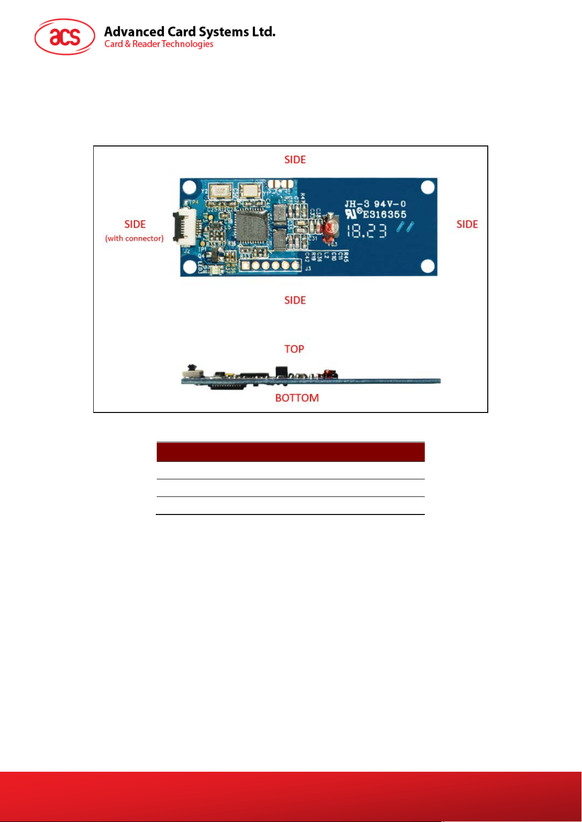
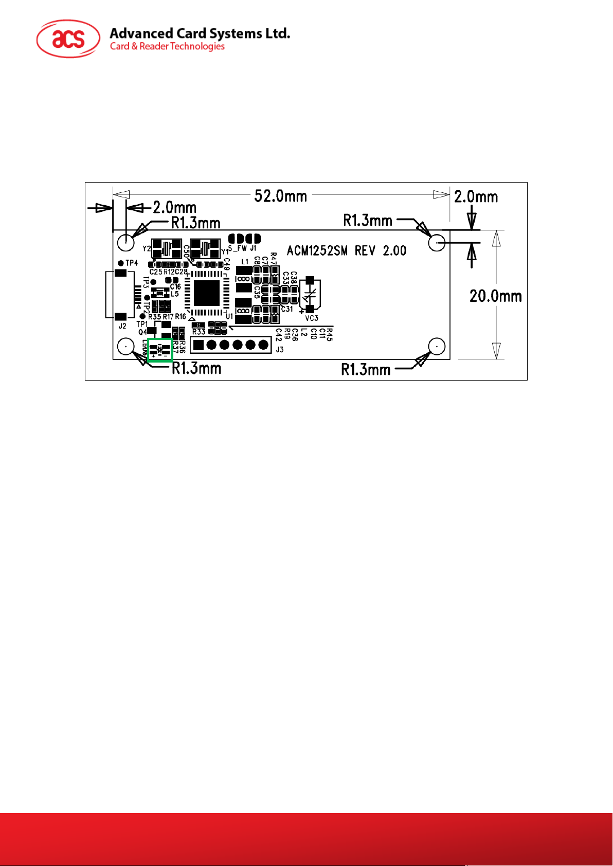
3.0. Minimum Distances from Conductive Materials
The table below illustrates the recommended minimum distances of the ACM1252U-Z6 from
conductive materials.
.
Location Minimum Distance
Sides 15 mm
Side (with connector) 5 mm
Top and Bottom 30 mm
Table 1: Recommended Minimum Distances from Conductive Materials
Page 6 of 7
ACM1252U-Z6 – User Manual info@acs.com.hk
Version 1.00
www.acs.com.hk
Page 7

Appendix A. Connector Specification
Figure 3: ACM1252U-Z6 USB Connector Specification
Note: The connector shown in Figure 3
is attached to the PCB.
Page 7 of 7
ACM1252U-Z6 – User Manual info@acs.com.hk
Version 1.00
www.acs.com.hk
 Loading...