

Page 1
PRODUCT
SUPPORT
MANUAL
Y1-03-0180
Rev. A
ThunderBird
SSAS
Ship Security Alert System
FCC Type Accepted
Model No. RLB-33S
Product No. 2800
Owner
Vessel
Radio Call Sign
ACR Electronics, Inc.
5757 Ravenswood Road
Fort Lauderdale, Fl 33312
+1(954) 981-3333 • Fax +1 (954) 983-5087
www.acrelectronics.com
Email: Info@acrelectronics.com
A Chelton Group company
Page 2
* * * WARNING * * *
THIS BEACON IS AUTHORIZED FOR USE
ONLY DURING SITUATIONS WHERE THE SECURITY OF YOUR VESSEL IS
UNDER THREAT OR HAS BEEN COMPROMISED AND POLICE ACTION IS
REQUIRED
DELIBERATE MISUSE MAY
INCUR A SEVERE PENALTY
***Attention***
This beacon MUST be reprogrammed by an authorized ACR distributor prior to installation and
use. Failure to do so will result in incorrect routing of a security alert.
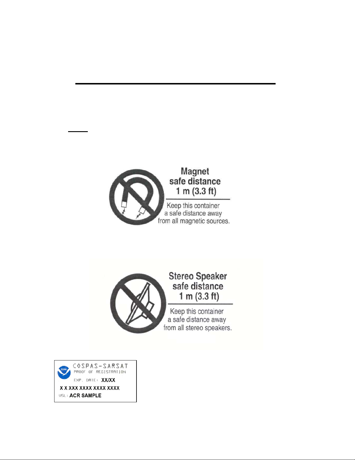
To ensure covert nature of the beacon, do not place the
proof of registration label onto your SSAS beacon. Attach
this label and all SSAS materials securely to your SSAS
Annex portion of your vessel security plan.
1
Y1-03-0180 Rev. A
Page 3

Forward
Congratulations and thank you for purchasing the ACR ThunderBird 406 MHz Ship Security Alert
System (SSAS). The combination of superior design, high quality raw materials and quality controlled
manufacturing produces a product that will perform for years to come. The Test Facility at ACR can
reproduce some of the harshest environmental conditions known to man. This assures that the products
we design and manufacture can stand up to the rigors found in a marine environment. With proper care
and maintenance, your SSAS will be in service for years to come.
ACR is proud to be certified to the ISO 9001:2000, the International Standard for Quality.
This manual provides installation, operation and maintenance instructions for the ThunderBird 406MHz
SSAS, hereinafter referred to as the Beacon. This manual also describes the characteristics and details of
the Beacon System. The FCC authorizes the use of 406 MHz Radio Beacon by any ship that is also
equipped with a VHF Ship Station. This will make the 406 MHz Radio Beacon available for use on most
U.S. ships and boats.
Table of Contents
1.0 Registration and Programming..............................................................................................3
2.0 False Alarms..........................................................................................................................5
3.0 Installation .............................................................................................................................6
4.0 Operation ...............................................................................................................................13
5.0 Care and Maintenance ...........................................................................................................17
6.0 The COSPAS-SARSAT System............................................................................................17
7.0 Authorizations, specifications and warranty..........................................................................20
8.0 Installation Checklist .............................................................................................................27
Figure 1..............................................................................................................................................7
Figure 2..............................................................................................................................................9
Figure 3..............................................................................................................................................9
Figure 4..............................................................................................................................................19
Figure 5..............................................................................................................................................19
Figure 6..............................................................................................................................................21
Figure 7..............................................................................................................................................22
Figure 8..............................................................................................................................................23
Figure 9..............................................................................................................................................24
Figure 10............................................................................................................................................25
Figure 11............................................................................................................................................25
Figure 12............................................................................................................................................26
2
Y1-03-0180 Rev. A
Page 4

SECTION 1 - REGISTRATION AND PROGRAMMING YOUR 406 MHZ BEACONS
1.1 Programming
This SSAS beacon is programmed with a serialized Unique Identifier Number (UIN). In order for
a security alert to be routed properly, this beacon must be reprogrammed by an authorized ACR
distributor before installation or use can occur.
This beacon must be reprogrammed as follows:
• With protocol code for SSAS
• With the country code of the vessel’s flag state
• With the vessel’s unique MMSI
1.2 Registration importance
It is imperative that the owner of this 406 MHz Beacon registers it with the National Authorities*.
All 406 MHz Beacons transmit a Unique Identifier Number (UIN) when activated. For SSAS the
UIN programmed in the Beacon must be the vessel’s MMSI. Registration provides the security
forces with up to date emergency contact information, which will speed up the launch of a rescue
operation. The National Authorities use the information to verify if an actual emergency exists.
Valuable resources are wasted every year responding to false alarms. For Beacons that are not
registered, the National Authorities will not know who you are, what type of vessel you have,
your homeport, or who has a copy of your float plan. This will delay the launch of the mission.
* National Authority is the governmental body that is responsible for SSAS registration database
administration for the country the SSAS is programmed for.
1.3 Where to register
The owner of a 406 MHz Beacon (SSAS) should register it with the National Authority of the
vessels flagged state, regardless of where they operate. Each Beacon must be programmed with
the country code of the vessels flag state, and will only be accepted for registration in that
country. To verify the country for which a Beacon is programmed, see the label with the UIN on
the back of the unit. Beacons purchased outside the flagged state of the vessel MUST be
reprogrammed by a properly equipped distributor for registration.
1.4 Registration in the United States
It is the Owner’s responsibility to Register 406 MHz Beacons that are programmed for and
purchased in the United States. The National Authority that accepts registrations in the United
States is the National Oceanic and Atmospheric Administration (NOAA). The owner should
complete the enclosed registration form (Do not confuse this with the ACR Electronics Warranty
Card) and mail with the pre-addressed; postage paid envelope to:
SARSAT Beacon Registration,
E/SP3, RM 3320, FB-4
NOAA/NESDIS
5200 Auth Rd.
Suitland, MD 20746-4304
Online registration is now available. Please visit - www.beaconregistration.noaa.gov
3
Y1-03-0180 Rev. A
Page 5

The information provided on the Registration Form is used only for rescue purposes. The
Registration Form should be filled out and mailed immediately. Registration can be expedited by
registering online or by faxing the registration form to Fax # (301) 568-8649. Registrations should
be faxed in the event the Beacon is to be placed in immediate service and followed up with the
mailing of the hard copy form.
All registration forms will be entered in the 406 MHz Beacon Registration Database within 48
hours of receipt. A confirmation letter, a copy of the actual registration and a proof-of-registration
decal will be mailed to you within two weeks. When you receive these documents, please check
the information carefully and place in the SSAS annex of your vessel security plan. Do not affix
the registration label to the beacon. This may compromise the covert nature of the beacon. (see
page 1). If you do not receive confirmation back from NOAA, Please call toll free 1-888-2127283 for assistance.
1.4.1 Commercial vessels in the United States
In the United States, commercial vessels that are required to have a Radio Station License are
required to modify that license when an SSAS is added to the vessel. Please update FCC FORM
605 to modify your Radio Station License. For information on whether you need a Radio Station
License, call toll free 1-888-CALLFCC (225-5322)
1.5 Registration outside of the United States
For use on vessels flagged in countries other than the United States, the sales agent should assist
in filling out the forms and sending to that country’s National Authority at the time of purchase.
To verify that the unit is properly programmed for that country, view the UIN label on the back of
the unit. In the event that the Beacon is not programmed for the country in which the vessel is
flagged, the sales agent (if properly equipped) MUST reprogram the unit for that country.
1.6 Change of ownership or contact information
It is the owner’s responsibility to advise the National Authority of any change in the information
on the registration form. If the current owner of the Beacon is transferring the Beacon to a new
owner, the current owner is required to inform the National Authority by Letter, Fax or telephone,
of the name and address of the new owner. The new owner of the Beacon is required to provide
the National Authority with all of the information requested on the Registration form. This
obligation transfers to all subsequent owners. In the United States registration forms are available
from NOAA. Call 1 (888) 212-7283 or visit
www.beaconregistration.noaa.gov
1.7 Commercial vessels worldwide
406 MHz SSAS Beacons that are carried on commercial vessels world wide, should be registered
with the country where the vessel is flagged regardless of where the vessel operates. When a
commercial vessel acquires a 406 MHz SSAS Beacon from outside of its flagged country; the
Beacon MUST be reprogrammed and register the beacon according to its flag state and its MMSI.
4
Y1-03-0180 Rev. A
Page 6

SECTION 2 - FALSE ALARMS
2.1 Prevention of false alarms.
There are a few precautions that should be taken to prevent false alarms:
Do not transport Beacon within 1 meter (3.3ft) of a magnetic source.
Do not mount Beacon within 1 meter (3.3ft) of a magnetic source.
Do not mount remote switches where they can be confused with another switch.
Do not mount beacon where it can get wet.
Do not clean beacon with any liquid.
2.2 Reporting of false alarms
Should there be, for any reason, an inadvertent activation or false alarm, it must be reported to the
National Authority of your vessels flagged state. The information that should be reported includes
the SSAS Unique Identifier Number (UIN), Date, Time, duration and cause of activation, as well
as location of beacon at the time of activation.
2.2.1 To report false alarms in the United States or Canada contact any of the following:
Atlantic Ocean / Gulf of Mexico
USCG Atlantic Area Command Center
Tel: (757) 398-6390
Pacific Ocean Area \ USCG Atlantic Area Command Center
Tel: (510) 437-3700
From Any Location
USCG HQ Command Center
Tel: (800) 323-7233
For Canadian Pacific waters:
Canadian Coast Guard Rescue Coordination Centre Victoria
Tel: (800) 567-5111
For Canadian Atlantic waters:
Canadian Coast Guard Rescue Coordination Centre Halifax
Tel: (800) 565-1582
For other Canadian waters (Great Lakes, Hudson’s Bay, Arctic)
Canadian Coast Guard Rescue Coordination Centre Trenton
Tel: (800) 267-7270
2.2.2 To report false alarms worldwide contact your national authority.
5
Y1-03-0180 Rev. A
Page 7

SECTION 3 - INSTALLATION
3.1 Preparation
3.1.1 Parts included:
Beacon/Mounting Bracket Assy Qty: 1 PN: A3-06-2410-1
Cross Dipole Antenna Qty: 1 PN: 2810
SMA Male Conn, RG-8/U Crimp Qty: 1 PN: 2814
Activation Switches Qty: 2 PN: 2820
Antenna Mount Qty: 1 PN: 2821
TNC Male Conn, RG-8/U Crimp Qty: 1 PN: 2633
Insulated Terminals, Crimp Qty: 4 PN: A1-05-0125-17
3.1.2 Tools Needed:
Phillips screwdriver
Drill
RG-8/U Crimp tool
Saw
Solder Iron
3.1.3 Additional Materials Needed for Installation:
Marine Grade RG-8/U Coaxial Cable
Switch wire or cable
Screws/Bolts for mounting bracket (3/16” or #10)
Screws/Bolts for Antenna Mount
3.2 Beacon Installation
3.2.1 The ThunderBird SSAS is shipped attached to its mounting bracket. Typically, the beacon must
be removed from the mounting bracket during installation. The beacon can be removed from the
mounting bracket as follows:
• First disconnect the 2-Pin waterproof connector on the left side of the beacon.
• Unbuckle the strap holding the beacon to the bracket.
The ThunderBird SSAS is intended to transmit covertly a security alert, notifying competent
authorities that the security of the vessel is under threat or has been compromised. A key
component of the system is its covert nature, which should be maintained as much as possible to
protect the beacon from malicious tampering.
The ThunderBird SSAS is shipped in the “OFF” position. During the installation procedure,
leave the beacon in the “OFF” position to prevent false alarms.
3.2.2 Mounting location
The location selected must be sufficiently rigid to support the weight of the total installation
(approx. 2 lbs) and at the same time consider vibration, exposure to surrounding hazards, such as
equipment movement, doors openings, personnel traffic, etc. The bracket should only be
mounted to a flat surface at least as big as the bracket. Mounting to a rail or post is not
recommended.
6
Y1-03-0180 Rev. A
Page 8
Also to be considered in selecting a location for installation is the harmful effect that certain
corrosive vapors might have on the beacon. Under no circumstances should a location be selected
for installation where the beacon would be jeopardized by any foreign articles being temporarily
or permanently positioned during “at sea” or “in port” activities.
Do not mount or store the beacon within 1 meter (3.3 ft) of strong magnetic (such as loud
speakers) or electrical (such as radar or high power radio transmitter) fields. The beacon should
not be mounted closer than 1 meter (3.3 ft) to a navigation compass.
In order to maintain the required covert operation, the ThunderBird SSAS mounting location
should be hidden from the view of most personnel and all passengers and guests. Suitable
locations include inside an equipment closet or cabinet, under the navigation bridge and inside a
closed equipment rack.
The bracket can be mounted in any orientation; however, the beacon controls and system
connections are designed for vertical installation. When selecting a mounting location the
following should be carefully considered:
• Routing of switch wires/cables. (Connects to top of mounting bracket.)
• Routing of RG-8U coaxial antenna cable. (Connects to top of beacon.)
• Routing of GPS interface cable. (Connects to top left part of beacon.)
• Accessibility to beacon control switch. (Top right part of beacon.)
• Visibility of Test and Xmit LED’s. (Top left part of beacon.)
3.2.3 Hardware
Use three Stainless Steel Pan Head fasteners to secure beacon mount to surface. Size 3/16” or
#10 bolts can be used. (Not Supplied)
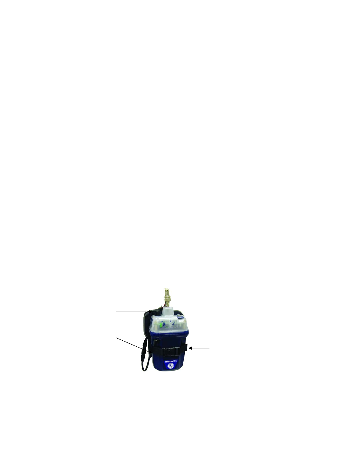
3.2.4 Installing the beacon in the bracket
The mounting bracket is keyed to prevent the beacon from being installed backwards. Install the
ThunderBird SSAS with the front label facing out. The strap should be tightened to secure the
beacon snugly in the bracket. Connect the 2-Pin waterproof connector on the left side of the
beacon.
GPS Interface Cable
2-Pin Waterproof Connector
ThunderBird SSAS correctly mounted in bracket
Bracket Mounting Strap
Figure 1
7
Y1-03-0180 Rev. A
Page 9

3.2.5 Connecting the beacon to a GPS receiver via the optical Interface (IR Transmitter)
Your Beacon comes with a NMEA GPS Optical Interface cable (transmitter plug with lead wires)
that should be connected to the ship’s GPS system. The IR transmitter plug attaches to your
Beacon, via the keyed blue bezel on the top left of the beacon. The cable can be routed through
the hole in the upper left corner of bracket. The lead wires attach to the ship’s GPS system via the
NMEA 0183 connector from your GPS receiver. The black lead wire with white stripes should be
connected to the positive transmitter pin (Data Out). The black wire should be connected to the
negative pin (Ground).
NOTE: The baud rate output for your GPS receiver NMEA 0183 should be 4800. Consult your
GPS manufacturer for correct installation.
3.3 Activation switch installation
• Per IMO’s SOLAS Chapter XI-2, Regulation 6: Ship Security Alert System:
o Paragraph 3.1: “The ship security alert system shall be capable of being activated from the
navigation bridge and in at least one other location;”
3.3.1 General information
SSAS beacons are required to have at least two remote activation points, one of which is on the
navigation bridge. Two switches are supplied with the ThunderBird SSAS. Contact the factory
if additional switches are required.
The switches are required to be protected from inadvertent activation and activate only with two
independent mechanical actions. These requirements are satisfied by the spring-loaded switch
guard attached to the switch when shipped. The switches must be installed with the guard in
place.
3.3.2 Switch location
The switches are designed to be installed through a hole in a panel and require approximately 1”
(25.4 mm) by 1” (25.4 mm) clearance on both the front and the back. The recommended panel
thickness is 0.039” (1mm) to 0.106” (3.2mm).
There are some additional factors that should be considered when selecting the switch locations.
A primary consideration is installing the switches per IMO requirements: one on the navigation
bridge and the other in a secondary covert location. Each switch should also be installed in a
location that will not draw unnecessary attention, yet be easy to access. The switches should not
be installed in a location where they might be confused with other switches. Lastly, the wiring
routing may also be considered.
3.3.3 Recommended wire
ACR recommends using stranded, tinned wire between 16 to 22 AWG to connect between the
remote activation switches and the beacon mounting bracket. Stranded wire is recommended to
better withstand the effects of vibration. Tinned wire is resistant to corrosion. The recommended
wire gauge is a compromise between weight and strength. ACR provides crimp-on terminal lugs
8
Y1-03-0180 Rev. A
Page 10

for 16 to 22 AWG wire for the connection to the mounting bracket. Other marine grade lugs (Not
Supplied) can be used for different gauge wire.
Because two wires are required to connect the switch to the mounting bracket, a two conductor
cable is ideal. This makes routing the wire easier and provides additional strength.
Activation button with recommended wire
soldered to the switch
3.3.4 Switch installation
Cut a 0.638” x 0.638” (16.2 mm x 16.2 mm) square hole in the selected panel. The recommended
panel thickness is 0.039” to 0.106” (1.0 mm to 3.2 mm).
The switch should be pushed back into the hole from the front. It is recommended to make the
wire connections before installing the switch into the panel. Connect the wires to the back of the
switch; one wire to “COM” terminal and the other to “N.O.” terminal. There should be no
connection to the “N.C.” terminal. The wires should be soldered to the switch terminals (see
figure 2). Once the connections are made, make sure the spring-loaded switch guard is securely
attached to the switch and press the switch assembly into the panel hole. The switch will snap
into place.
Repeat the above procedure for the other switch.
3.3.5 Connection to mounting bracket
Route the switch wire from the switch locations to the ThunderBird SSAS beacon mounting
bracket. Care should be taken to route and secure the wire properly. The wires should then be
trimmed to the appropriate length.
If using the recommended 16 to 22 AWG wire, crimp the terminal lugs (provided) onto the wires.
If other wire is used, appropriate lugs (Not provided) can be used. Alternatively, the wire can be
connected directly to the terminal block on the mounting bracket (see figure 3). Connect one wire
from each switch to one of the two terminals on the top of the mounting bracket by placing the lug
under the screw and tightening the screw. Repeat with the other wire from each switch in the
other terminal.
Wiring connection on the
mounting bracket coming from
Activation switch
Figure 3
9
Y1-03-0180 Rev. A
Page 11

3.3.6 Switch installation verification
To verify proper installation of the switches, the following procedure should be followed (requires
two persons, preferably with 2-way radio communications):
• Perform this procedure with all connections made between the switches and the beacon.
• The beacon must be in OFF mode. Performing this test with the beacon in READY mode
may result in a live transmission to the satellite system.
• With a multi-meter, measure the resistance between the two screws on the left side of the
beacon. This should be an open circuit (> 100 kΩ.) If not, check the switch wire connections
to make sure the two wires from each switch are connected to different screws on the
mounting bracket terminal block.
• Depress each switch (one at a time) while measuring the resistance between the two pins on
the mounting bracket connector. The resistance should momentarily (as long as the switch is
depressed) read a short (< 10Ω.) If the resistance never reads a short, verify all connections
are per 3.2.4 and 3.2.5 above.
3.4 Cross dipole antenna installation
3.4.1 General information
The cross dipole antenna is intended for operation far away from a ground plane. With this in
mind, the location of installation should be carefully selected to keep the antenna as far from
horizontal conductive (metallic) planes as possible (see figure 6 on page 22).
The length of cable from the SSAS beacon to the cross dipole should be kept as short as possible.
Secure antenna cable (3 ft. maximum) away from antenna to reduce stress on antenna connector
(see figure 9).
A stainless steel 4 inch tall antenna mount is included with your SSAS kit. If the supplied bracket
is not ideal for the desired mounting location, the cross dipole has a standard female 1” x 14
thread allowing it to be mounted to a variety of off-the-shelf brackets and masts.
3.4.2 Mounting guidelines
• Minimum height above deck: 10 feet (3 m)
• Allowable obstructions: Obstructions are allowable only below the antenna.
There should be no conductive (metallic) objects in
the entire hemisphere above the antenna.
• Coaxial cable length: Maximum: 100 feet (30.5 m)
* Contact the factory if longer runs or different
coaxial cable is required.
• Coaxial cable type: RG-8/U Marine Grade
10
Y1-03-0180 Rev. A
Page 12

3.4.3 Antenna assembly
The antenna is shipped with the four elements removed from the housing. Before using the
antenna, these elements must be assembled to the antenna housing.
For each element, assemble as follows:
1. Slide the grooved end of the element into a hole in the side of the housing until it stops
2. Install and tighten appropriate set screw through hole in the bottom housing using included
wrench
3. Pull lightly on the element to ensure it is tightly secured
3.4.4 Antenna installation
Select mounting location using guidelines and general information above. The top of a mast is an
ideal location for the cross dipole. Mounting to an existing spar or to a bracket attached to a mast
is also acceptable. See Figure 6 on page 22 for examples. The antenna must be mounted with the
connector pointing down and the elements horizontal. If mounting on a spar or bracket, the
antenna elements must be oriented approximately 45° to the horizontal support when looking
from the top or bottom, as shown in Figure 6.
Use one of the following methods to mount the antenna per the guidelines and general
information above with all four elements in the horizontal plane:
• The included mount can be used to attach to any small, flat, horizontal surface; i.e. the top of a
mast or a spar. In this case drill holes in the pattern of the mount and attach with marine grade
screws as needed (not supplied).
• The included mount can be used to attach the antenna to a round spar using U-bolts.
• The antenna can be mounted to any bracket or mast with the standard 1” x 14 thread.
3.4.5 Connection to beacon
Attach male TNC connector (supplied) to marine grade RG-8/U coaxial cable (Not provided) as
follows:
• Strip the coax cable per Figure 7.
• Solder the connector pin to the center conductor.
• Slide the ferrule over the cable.
• Slide the cable/pin assembly into the connector body. Make sure the pin goes into the center
of the connector insulator and the braid goes over the knurled part of the back of the
connector.
• Slide the ferrule to the back of the connector.
• Using an RG-8/U die (approx. 0.429”), crimp the ferrule tightly over the cable and connector.
11
Y1-03-0180 Rev. A
Page 13

Connect the male TNC cable assembly to the mating female TNC connector on antenna.
Slide wire thru mounting bracket to
connect to antenna
Fasten TNC cable assembly to the mating
female TNC connector on antenna
Secure antenna to the mounting
bracket
Route cable to SSAS beacon as needed, making sure to adequately secure the cable. Provide a
drip loop in the cable near the beacon to prevent water from running directly on to the beacon.
Trim the cable to the appropriate length.
Attach male SMA connector (supplied) to marine grade RG-8/U coaxial cable as follows:
• Strip the coax cable per Figure 8.
• Solder the connector pin to the center conductor.
• Slide the ferrule over the cable.
• Slide the cable/pin assembly into the connector body. Make sure the pin goes into the center
of the connector insulator and the braid goes over the knurled part of the back of the
connector.
• Slide the ferrule to the back of the connector.
• Using an RG-8/U die (approx. 0.429”), crimp the ferrule tightly over the cable and connector.
Connect the male SMA connector on the cable assembly to the mating female SMA connector on
the beacon.
3.4.6 Antenna Installation Verification
To verify proper installation of the Cross Dipole antenna, the following procedure should be
followed (requires two persons, preferably with 2-way radio communications):
• One person should be on the deck with an FPR-100 with line-of-sight view of the Cross
Dipole antenna. The FPR-100 antenna should be oriented horizontally and ideally be located
directly under the Cross Dipole antenna.
• With the FPR-100 ready to receive a test burst, the other person should initiate a Self-Test.
• If the FPR-100 successfully receives the test burst, then the Cross Dipole antenna is installed
correctly.
• The FPR-100 can also verify that the ThunderBird SSAS is programmed correctly.
12
Y1-03-0180 Rev. A
Page 14

• If the test burst was not received, the FPR-100 may be too far from the antenna. Repeat the
test with the FPR-100 closer to the antenna. (Typically, an FPR-100 can receive a signal from
the cross dipole at a maximum range of 100 ft. (30.5m).
• If the FPR-100 still does not receive the test burst, check all coaxial connections from the
beacon to the antenna.
SECTION 4 - OPERATION
4.1 General
4.1.1 The ThunderBird SSAS Beacon can only be activated manually while installed in the mounting
bracket.
4.1.2 The following two conditions must be satisfied to activate the ThunderBird SSAS:
1) The switch on the beacon must be placed in the “READY” position.
2) One of the remote activation switches must be depressed.
4.1.3 The ThunderBird SSAS is designed to allow the user to perform periodic testing while SSAS is
in the mounting bracket, to assure a functioning beacon.
4.2 Controls
4.2.1 Thumb Switch: The thumb switch on the top right side of the beacon controls the mode of
operation of the ThunderBird SSAS. There are three switch positions (see figure 5):
1) Off: Down to the front, indicated by “O”
2) Self-Test: Vertical
3) Ready: Down to the back, indicated by “I”
4.2.2 Remote activation switches: These are momentary switches installed on the ship that are used to
activate the beacon when the beacon is placed in READY mode. To activate, lift the springloaded guard and press the button.
Note: Once the beacon has been activated, it must be manually deactivated.
4.3 Indicators
4.3.1 LED’s:
There are two LED indicators located on the top right part of the beacon:
1) TEST LED: Green
2) XMIT (transmitting) LED: Red
4.3.2 Buzzer:
There is an internal buzzer in the ThunderBird SSAS. The buzzer beeps only during the
Self-Test.
4.3.3 There are no indicators of the beacon’s mode of operation at the remote activation points.
4.3.4 There is no audible indication while in the transmission (operating) mode.
13
Y1-03-0180 Rev. A
Page 15

4.4 Modes of operation
4.4.1 OFF Mode: The ThunderBird SSAS can not be activated when in OFF mode. The beacon is in
OFF mode whenever the thumb switch is in the “Off” position (down to the front) as indicated by
the “O” symbol displayed on the thumb switch.
4.4.2 READY Mode: The ThunderBird SSAS is capable of being activated when in READY mode.
The beacon is in READY mode whenever the thumb switch is in the “Ready” position (down to
the back) as indicated by the “I” symbol displayed on the thumb switch.
4.4.3 ON Mode: The ThunderBird SSAS is activated and is transmitting bursts of data when in ON
mode. The beacon is in ON mode when one of the remote switches is depressed while the beacon
is in READY mode. ON mode is indicated by a flashing red XMIT LED.
4.4.4 SELF-TEST Mode: The ThunderBird SSAS is in SELF-TEST mode while it is performing the
self-test. The beacon goes into SELF-TEST mode when the thumb switch is held in the Self-Test
position (vertical) for at least 1 second. SELF-TEST mode is indicated by a series of flashing
green TEST LED and red XMIT LED’s and beeps as detailed in section 4.7.
4.5 Activation
An ACR 406 MHz SSAS can be activated by two different methods.
1. With the beacon switch in the ready position and depressing one of the buttons of the remote
activation points, or
2. With the beacon switch in the ready position and shorting the two wire leads from the beacon.
4.5.1 The ThunderBird SSAS can be manually activated by first placing the beacon in READY mode.
This is done by lifting the thumb switch to a vertical position, sliding it to the left and pushing it
down to the back side of the SSAS READY mode is indicated by the " I " symbol displayed on
the thumb switch.
4.5.2 Once in READY mode, the ThunderBird SSAS is activated by depressing one of the remote
activation switches. At the remote activation locations, there is no indication that the beacon is
activated. This is intentional to ensure covert operation. The flashing red XMIT LED on the
beacon indicates activation.
4.5.3 The ThunderBird SSAS should only be activated when the ships security has been threatened or
compromised. However, applicable personnel must be familiar with its operation so the beacon
can be activated when needed.
4.6 Deactivation
4.6.1 The ThunderBird SSAS can be deactivated by returning the thumb switch to the “OFF” position.
4.6.2 If the beacon continues to operate after it has been deactivated, remove the four screws holding
the top cap to the bottom case assembly and unplug the battery to disable the unit. Return it to a
Service Center for repair.
14
Y1-03-0180 Rev. A
Page 16
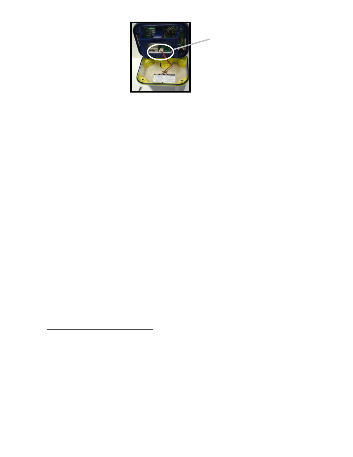
Battery connection Plug
4.7 Full functional Self Test
Please read all instructions before performing any of the tests. Be prepared to record data from
the test.
4.7.1 The ThunderBird SSAS can be tested in or out of the release bracket. A Self Test is initiated by
lifting the thumb switch to a vertical position and holding it in this position for at least one
second. The initiation of the test is indicated by the simultaneous and brief lighting of the green
and red LED's.
The sequence of tests is:
1. Check Data Integrity.............................................Beep and lights up LED if passed
...................................................................................Stop if failed
2. Check 406 MHz Synthesizer ................................Beep and lights up LED if passed
..................................................................................Stop if failed
3. Check RF Power/Battery......................................Beep and lights up LED if passed
..................................................................................Stop if failed
4. GPS Header...........................................................Beep and lights up LED if passed
..................................................................................Stop if failed
If all of the above occurs, the test has been successful.
4.7.2 It is strongly recommended to test the ThunderBird SSAS on a Monthly basis.
4.8 External GPS Interface
4.8.1 External GPS Interface Requirements:
In order to be compatible with the ThunderBird SSAS an
external GPS receiver must provide location information according to the following requirements:
• NMEA 0183, Version 1.5 or higher
• Baud Rate: 4800
• Talker Device Identifier: GP (GPS Receiver)
• Sentence Format: GGA (GPS Fix Data)
4.8.2 Using the GPS Interface: Once a compatible operating GPS receiver is connected to the Beacon,
the beacon will store GPS data for incorporation into the emergency message, which is
transmitted to the satellite. This can provide more accurate positioning data to the National
Authority and may lead to faster response. Since the last valid GPS position data is always kept in
the memory of the Beacon, the user should take care to make sure that the GPS position data
15
Y1-03-0180 Rev. A
Page 17

stored is accurate. This can be accomplished by two methods: First, by always leaving a properly
functioning GPS receiver connected to the Beacon before activation. Second, by connecting a
properly functioning GPS receiver with a valid position fix to the Beacon and allowing sufficient
time for the Beacon to acquire valid position data from the GPS. This will take a nominal 20
minutes if old GPS position data is stored in the Beacon’s memory. If GPS data is not stored, the
Beacon will acquire current data within a minute of being connected to a GPS with a valid
position fix. You can force the Beacon to update its position at any time by initiating the Beacon’s
Self-Test, see 4.8.3 and 4.8.4. If valid GPS position data is not available, it is preferable to reset
the Beacon with the beacon’s default message (See Section 4.8.5).
4.8.3 Testing the GPS Interface: Connect the Optical Interface Plug to the Beacon bezel and allow
sufficient time for the GPS receiver to acquire valid GPS position data (usually less than 1
minute; but it can take up to 30 minutes). Lift the thumb switch to the vertical (Self-Test) position
and release. Your Beacon will confirm that it has acquired valid GPS data by emitting a beep
along with a flash of the green LED. This will occur approximately 2.5 seconds after the SelfTest.
4.8.4 Updating GPS Position data: When the beacon is properly connected to a functioning and
compatible GPS receiver, GPS position data is automatically updated about every 20 minutes,
while valid GPS position data is present. The operator can force the acquisition of new GPS
position data, by executing Self-Test of the beacon. This bypasses the normal, programmed,
waiting time of 20 minutes for the automatic update of GPS position data. Once the beacon has
completed the Self-Test sequence by emitting the beep and flash of red and green LEDs, as
described in 4.8.3, the Beacon will request and acquire new position data from the GPS. This can
take a nominal 15 seconds or up to one minute.
NOTE: When the beacon is not activated, GPS position data will be received and stored by the
Beacon (No GPS position data updates will occur while the beacon is activated. However,
subsequent position information is determined by the Cospas-Sarsat Satellite System as
described in Section 6.)
4.8.5 Position data set to default: A new ThunderBird SSAS is programmed with the GPS position
data set to “default”. This “default” GPS position data indicates, upon activation, to the satellite
system that the beacon has no valid GPS position stored in memory. Once a functioning and
compatible GPS receiver is properly connected to the beacon, this “default” data will be replaced
by valid GPS position data, as described in the previous sections.
Position data will be reset to default by activating the beacon (by placing the thumb switch in
the ready position and then pressing one of the remote activation points) and then turning the
beacon off by returning the thumb switch to the off position. Once the beacon is in ON mode, it
must be turned OFF within 45 seconds to prevent transmission of a live burst. Because the
activation points must be remote from the beacon, it is recommended that two people with 2Way radios perform this procedure to prevent false alarms.
NOTE: THIS BEACON IS AUTHORIZED FOR USE ONLY DURING SITUATIONS
WHERE THE SECURITY OF YOUR VESSEL IS UNDER THREAT OR HAS BEEN
COMPROMISED AND POLICE ACTION IS REQUIRED.
ALSO NOTE: The action of turning the beacon ON and then OFF clears any stored GPS position
data.
16
Y1-03-0180 Rev. A
Page 18

SECTION 5 - CARE AND MAINTENANCE
5.1 At least every ninety days, the mounting bracket, antenna and beacon should be inspected for
deterioration and/or buildup that may affect the function of the beacon or it’s mounting.
Also carefully inspect the beacon case for any visible cracks. Cracks may admit moisture, which
could falsely activate the beacon or otherwise cause a malfunction. Any cracking observed
should be immediately referred to ACR for evaluation, (1-800-432-0227 Ext. 112).
Carefully inspect the antenna for excessive corrosion of metal parts and visible cracks on the
plastic housing. These could result in a malfunction of the antenna. Any of the above should be
immediately referred to ACR for evaluation. Antenna accessories and rebuild kits are available if
the antenna should be damaged. (See page 21 for more details).
5.2 Clean the beacon and the mounting bracket to remove residue buildups. It is recommended that
the mounting bracket be wiped with a damp cloth.
5.3 Check coaxial connector on cable from the antenna for tightness.
5.4 The battery (P/N 1096) must be replaced by the date indicated on the beacon. At each inspection,
check the time remaining until replacement is required. Battery should be replaced if the beacon
has been activated for any use other than the self test.
NOTE: There are no user serviceable items inside the SSAS. DO NOT OPEN THE SSAS
UNLESS TO DISABLE IN CASE OF FAULTY ACTIVATION.
Self contained long life batteries with a five-year recommended replacement cycle provide power.
See Factory Authorized Service Center for replacement.
Battery replacement includes: replacement of the lithium battery pack and proper disposal,
replacing all o-rings, testing the water seal and performing a full electrical diagnostic check.
Always refer all battery replacement and other SSAS service to a factory authorized service
center.
For the nearest location of a factory authorized service center, call 1-800-432-0227 Ext. 112 (toll
free) or visit our website at
www.acrelectronics.com
5.5 The ThunderBird SSAS contains lithium batteries which meet the requirements of the DOT
Hazardous Materials Regulations. They also meet the United Nations Classification of Lithium
Batteries for Shipment as “Non – Dangerous Goods”.
SECTION 6 – THE COSPAS-SARSAT SYSTEM
6.1.1 The ThunderBird SSAS Beacon provides security alerting via radio transmission on 406 MHz to
satellites of the COSPAS-SARSAT network. The beacon can also transmit a distress alert to the
GEOSAR network that includes GPS latitude and longitude coordinates that are inputted through
an I/R Interface that connects to the data output of a GPS Receiver.
17
Y1-03-0180 Rev. A
Page 19

6.1.2 The message transmitted by the ThunderBird SSAS is unique for each SSAS, which provides
identification of the transmitter through computer access of registration files maintained by the
National Oceanic and Atmospheric Administration or other national authority. It is the user’s
responsibility to fill out and mail the enclosed registration form to the appropriate agency of
the country under which the vessel is registered. US flagged vessels send the enclosed
NOAA/NESDIS form to NOAA in the stamped envelope provided. For vessels registered in other
countries, the beacon must be reprogrammed by an ACR authorized programming facility for the
registered country. Remember, if your SSAS is not registered, security Authorities do not know
who you are, what type of vessel, your homeport, or where to contact anyone who might know
anything about your situation.
6.1.3 Once the beacon’s signal (406 MHz) is relayed through the COSPAS-SARSAT and/or GEOSAR
network and security forces are alerted, they can converge on the GPS navigation position or the
position estimated by the satellite. When the GPS interface is used with a properly functioning
GPS system, security authorities can know your precise location immediately and speed up
reaction time.
6.2 Satellite detection
6.2.1 The ThunderBird SSAS transmits an encoded phase modulated radio signal to the satellite
portion of the COSPAS-SARSAT System. The system was developed and implemented by the
COSPAS-SARSAT Partners (Russian Federation, Canada, France and the United States).
6.2.2 COSPAS-SARSAT is an international system that uses Russian Federation and United States low
altitude, near-polar orbiting satellites that assist in detecting and locating activated 406 MHz
beacon signals. The Russian Federation provides aboard COSMOS navigation spacecraft
COSPAS payloads that are inter-operable with the SARSAT System. In addition to weather and
environmental sensors, SARSAT payloads, provided by Canada and France, are carried aboard
the United States National Oceanic and Atmospheric Administration’s (NOAA’s) Advanced
TIROS environmental satellites. (See Figure 1: Satellite Coverage)
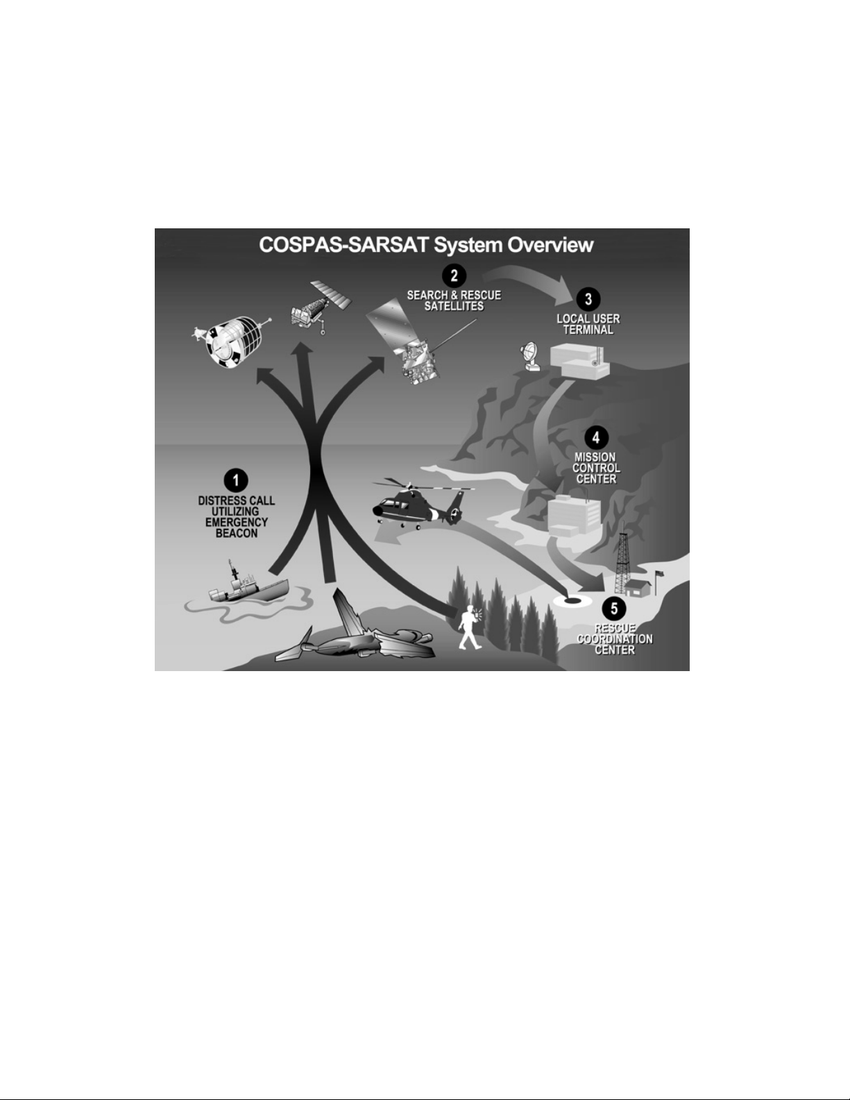
6.2.3 COSPAS and SARSAT satellites receive distress signals from satellite beacons transmitting on
the frequencies of 406.025 and 406.028 MHz. The COSPAS-SARSAT 406 MHz satellite SSAS
signal consists of a transmission of non-modulated carrier followed by a digital message format
that provides identification data. The 406 MHz system uses spacecraft-borne equipment to
measure and store the Doppler-shifted frequency along with the satellite SSAS digital data
message and time of measurement. This information is transmitted in real time to an earth station
called the Local User Terminal (LUT), which may be within the view of the satellite, as well as
being stored for later transmission to other LUTs. In the real-time mode, the signal detection is
limited to a mutual SSAS –satellite-LUT circular visibility area of about 2500 km radius that
moves with the satellite along its track. However, because of the stored-mode capability at 406
MHz, the need for this mutual SSAS –satellite-LUT visibility is not essential, and the system is
fully functional worldwide.
6.2.4 The LUT processes the Doppler-shifted signal and determines the location of the satellite SSAS;
then the LUT relays the position of the distress to a Mission Control Center (MCC) where the
distress alert and location information is immediately forwarded to an appropriate maritime
Rescue Coordination Center (RCC). The RCC dispatches security forces.
18
Y1-03-0180 Rev. A
Page 20
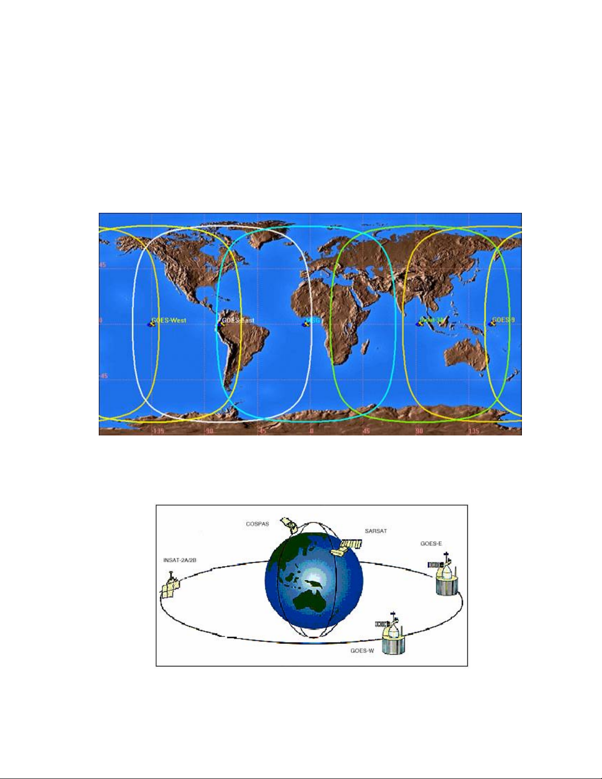
6.2.5 The COSPAS-SARSAT System includes 36 LEOSAR LUT stations, 6 GEOSAR LUT stations
and 19 Mission Control Centers that provide real-time as well as global-mode coverage for the
Northern Hemisphere, while the Southern Hemisphere is presently served primarily by the global
mode. Additional LUTs and MCCs are planned for installation in the near future both in the
northern and southern hemispheres.
The addition of the GEOSAR Satellite system greatly improves the reaction time for a security
event. This satellite system has no Doppler capabilities at 406 MHz but will relay the distress
alert to any of the LUT stations. When there is GPS data included in the distress message this
will instantly tell SAR authorities where you are located at. Hence speeding up the reaction time
by not having to wait for one of the LEOSAR satellite’s to come around.
GEOSAR SATELLITE COVERAGE
FIGURE 4
SAR SATELLITE ORBITS
FIGURE 5
19
Y1-03-0180 Rev. A
Page 21

SECTION 7 - AUTHORIZATIONS
7.1 Type Approvals
7.1.1 The ThunderBird SSAS meets the requirements of Federal Communications Commission (FCC)
Part 80 and GMDSS. FCC ID: B66ACR-RLB-33S
7.1.2 COSPAS-SARSAT Type Approval Certification No.141
7.2 Characteristics
7.2.1 The ThunderBird SSAS is a floatable, battery operated unit. The beacon case, with its external
antenna, is waterproof. The semiconductor circuits are mounted within the case assembly that also
contains the battery power supply. A thumb switch is installed on top of the beacon. The beacon
must be stored in its special mount.
7.3 Technical data — ThunderBird SSAS (P/N 2800)
7.3.1 Applicable Documents
IMO Chapter XI-2, Regulation 6: Ship Security Alert System
RTCM Recommended Standards for Ship Security Alert Systems (SSAS) Using
the Cospas-Sarsat Satellite System
COSPAS-SARSAT Interim Cospas-Sarsat Type Approval Guidelines for 406 MHz SSAS
Beacons
FCC Part 80 and GMDSS
7.3.2 Specifications
406 MHz Transmitter
Frequency 406 MHz
Frequency Stability ±2 parts per billion/100ms
Output Power 5 watts
Digital Message
Format
Serialized
1
Duration 520 ms
Rate 400 bps
Encoding Biphase L
Modulation ±1.1 radians peak
Antenna
Frequency 406 MHz
Polarization Right-Hand Circular (RHCP)
VSWR Less than 1.5:1
General/Environmental
Battery Life
Operating 48 hours minimum
Replacement Interval 5 years
20
Y1-03-0180 Rev. A
Page 22
Size
SSAS less Antenna 7.20” (18.29 cm)
Material, SSAS High impact and UV resistant plastic
Color Blue
Weight 1.9 lbs. (862 g)
Temperature Range
Operating -25°C to +55°C
Stowage -25°C TO +70°C
1
Leaves ACR with Serialized U.S. code but must be reprogrammed at an authorized ACR Service
center with SSAS protocol code, the vessels Maritime MMSI and country code of the flag state
before installing on a ship.
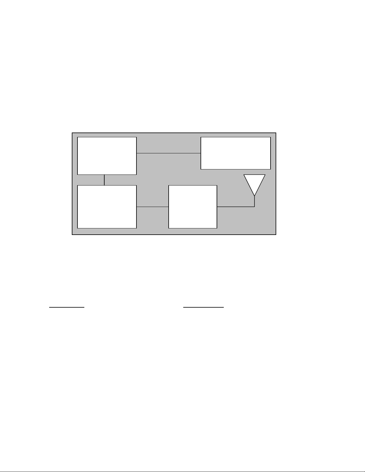
µP
USER /
PROGRAMMING
INTERFACE
406 MHz
RF
AMPLIFIER
SSAS BLOCK DIAGRAM
FIGURE 6
7.3.3 Accessories
Description
Part Number
Replacement Cross Dipole Antenna 2810
Cross Dipole Rebuild Kit 2811
Marine Grade RG-8/U Cable 2812.1 (10 m)
2812.2 (20 m)
2812.3 (30 m)
Activation Switch Cable 2813.1 (5 meters)
2813.2 (10 meters)
Additional Activation Switch 2820
Antenna Mount 2821
21
Y1-03-0180 Rev. A
Page 23
* * * WARNING * * *
THIS BEACON IS AUTHORIZED FOR USE
ONLY DURING SITUATIONS WHERE THE SECURITY OF YOUR VESSEL IS UNDER
THREAT OR HAS BEEN COMPROMISED AND POLICE ACTION IS REQUIRED
COSPAS-SARSAT System Overview
FIGURE 7
22
Y1-03-0180 Rev. A
Page 24
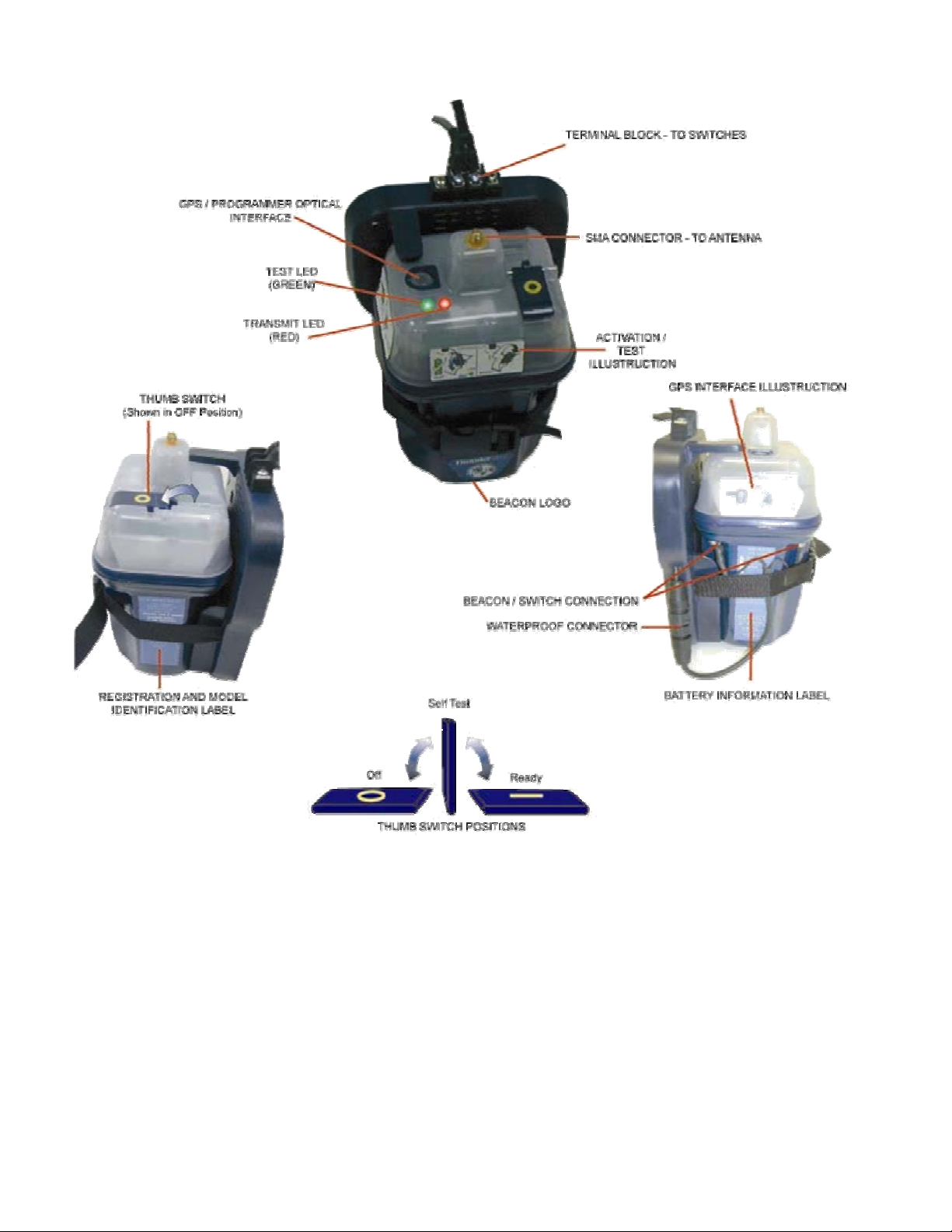
ACR THUNDERBIRD
FIGURE 8
23
Y1-03-0180 Rev. A
Page 25
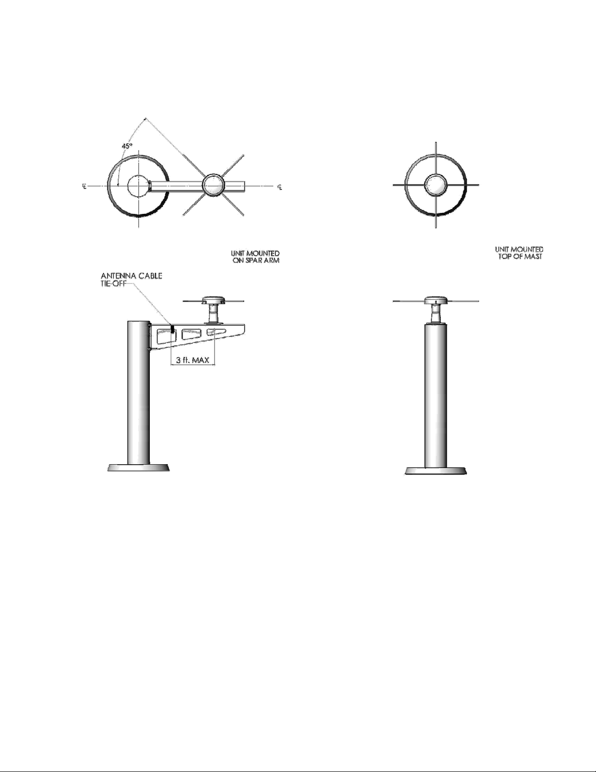
ANTENNA INSTALLATIONS
FIGURE 9
24
Y1-03-0180 Rev. A
Page 26

INCH (mm)
RECOMMENDED CABLE STRIPPING DIMENSIONS
FOR TNC CONNECTOR
FIGURE 10
INCH (mm)
RECOMMENDED CABLE STRIPPING DIMENSIONS
FOR SMA CONNECTOR
FIGURE 11
25
Y1-03-0180 Rev. A
Page 27

FIGURE 12
SSAS SYSTEM
BLOCK DIAGRAM
26
Y1-03-0180 Rev. A
Page 28

INSTALLATION CHECK LIST
Please Review to ensure you have properly installed this SSAS beacon:
Installed the beacon and bracket on a flat vertical surface in a discreet location. (Paragraph 3.2)
Installed the activation switches. (Minimum of two.)
One must be on the navigation bridge.
Switches shall not be labeled. (Paragraph 3.3.4)
Connected switch wire to switches and terminal block on the top of the mounting bracket. Route
wire appropriately. (Paragraph 3.3.5)
Assembled the antenna using the rods, set screws and wrench provided. (Paragraph 3.4.3)
Installed the antenna in a location at least at least 10 ft (3 m) above deck and with clear view of
the sky using either the included 4” mount or other mount with compatible 1” x 14 threads.
(Paragraph 3.4.4)
Connected antenna to beacon using SMA and TNC connectors provided and RG-8/U coaxial
connector. Route cable appropriately. (Paragraph 3.4.5)
Upon completion of the installation, perform the Activation Switch (Paragraph 3.3.6) and Cross
Dipole Antenna (Paragraph 3.4.6) Installation Verification Tests.
Upon successful completion of Installation Verification Tests, place the beacon in READY mode.
ADDITIONAL NOTES:
27
Y1-03-0180 Rev. A
 Loading...