

Page 1

PRODUCT
SUPPORT
MANUAL
Y1-03-0165
Rev. B
SM-2
Product No. 3940.1
Automatic Crew-Overboard Light
ACR Electronics, Inc.
5757 Ravenswood Road
Fort Lauderdale, Fl 33312
+1(954) 981-3333 • Fax +1 (954) 983-5087
www.acrelectronics.com
Email: Info@acrelectronics.com
A Cobham plc Company
Page 2

Forward
Congratulations and thank you for purchasing the ACR SM-2 Automatic Crew-Overboard Light. The
combination of superior design, high quality raw materials and quality controlled manufacturing produces a
product that will perform for years to come. The Test Facility at ACR can reproduce some of the harshest
environmental conditions known to man. This assures that the products we design and manufacture can
stand up to the rigors found in a marine environment. With proper care and maintenance, your SM-2 light
will be in service for years to come.
ACR is proud to be certified to the ISO 9001:2000, the International Standard for Quality.
This manual provides installation, operation and maintenance instructions for the SM-2 light.
* * * Caution * * *
In order for the marker light to float properly, the 6 volt battery MUST not weigh more than 675 grams
(1.49 lbs). Exceeding this weight will cause the light to sink.
Test light buoyancy in shallow water prior to placing in service.
The following battery types are suggested for use in ACR Marker lights:
Suggested Screw Terminal batteries:
ANSI/NEDA: 915, 915C, 915D, 915AC
Duracell: M915, PC915
Rayovac: 942, 945
Eveready: 510S
Suggested spring terminal batteries (for use with optional battery adapter 9434):
ANSI/NEDA: 908, 908C, 908D, 908AC
Duracell: M908, PC908
Eveready: 509, 1209
Energizer: EN529, (not 529)
Rayovac: 941, 944
Panasonic: W-4FD
Note: Check adapter to ensure that screws are tight during regular maintenance.
1
Y1-03-0165 Rev. B
Page 3

TABLE OF CONTENTS
PARA. TITLE PAGE
1.0 SECTION 1 - CHARACTERISTICS 3
1.1 General 3
1.2 Purpose 3
1.3 Component Ratings 3
1.4 Operation 3
1.5 Effect of Testing 3
1.6 Encapsulating Materials 3
1.7 Construction 4
1.8 Lanyard 4
1.9 Case 4
1.10 Lens 4
1.11 Ballast 4
1.12 Mounting Bracket 4
1.13 Dimensional Stability and Vapor proofness 4
1.14 Battery Connection 5
1.15 Buoyancy 5
1.16 Stroboscopic Flashing Light 5
1.17 Technical Data SM-2 6
Figure 1 Outline and Dimensional Sketch 7
Figure 2 Instruction Plate Label 8
2.0 SECTION 2 - INSTALLATION 9
2.1 Installation Procedures 9
2.2 Battery Installation 9
3.0 SECTION 3 - TESTING 9 - 10
3.1 Operation 9
3.2 Inspection 9
3.3 Disassembly 9 - 10
3.4 Assembly 10
- - - - SM-2 Parts List 11
Figure 3 SM-2 Exploded View 12
2
Y1-03-0165 Rev. B
Page 4

1.0 SECTION 1 - CHARACTERISTICS
1.1 GENERAL
This section describes operating instructions and operational characteristics of the SM-2 Automatic
Crew-overboard light. The information presented herewith is in conformance with U.S. Coast Guard
Specification 46 CFR 161.010 and 161.110.
The SM-2 is a lightweight, compact, battery operated, portable unit which uses modular
construction for basic circuits to simplify maintenance and replacement procedures.
The SM-2 has been redesigned and strengthened to pass the tough UL 1196 testing and MSC.81(70)
1.2 PURPOSE
This unit, shown in Figure 1, is a portable, electronic, floating strobe light, which automatically
rights itself and begins flashing when dropped into water. The SM-2 Light is designed to be carried
aboard all vessels, as well as artificial islands and fixed structures which are located on the outer
continental shelf. It is to be used as part of the required survival equipment complement. The light is
used to mark a position in the water, particularly in a crew-overboard situation. It must be installed
and used in conjunction with other equipment as required by U.S. Coast Guard Regulations.
1.3 COMPONENT RATINGS
Circuit design and component selection is such that component ratings cannot be exceeded when the
unit is operated throughout the entire range of all environmental tests. The SM-2 uses circuit
components and construction techniques, which have been manufactured to the specifications and
requirements of various civilian and Governmental agencies.
1.4 OPERATION
Instructions for operation and maintenance of the SM-2 Light are given on the instruction plate.
(See Figure 2) This unit does not possess any exterior operating controls. Equipment design is such
that controls for use during normal operation would not be detrimental to the reliability of the Light.
The circuit is electronically activated by a gravity switch when the unit is inverted.
1.5 EFFECT OF TESTING
Equipment design is such that application of specified tests will provide no discernible condition
which would be detrimental to the reliability of equipment manufactured in accordance with such
design.
1.6 ENCAPSULATING MATERIALS
Materials used to encapsulate the Module are of the type that will not have any injurious effect on
the insulating materials to which they are applied and do not cause corrosion or deterioration of any
adjacent part. These compounds do not flow at temperatures below +85° C or crack at temperatures
down to -34° C.
3
Y1-03-0165 Rev. B
Page 5

1.7 CONSTRUCTION
The SM-2 Light essentially consists of a case with a battery, switch, electric circuit, flashlamp,
globe, lanyard attachment flange, a mounting bracket, and a buoyant, non-absorbent unicellular
polyfoam, used as filler material.
1.8 LANYARD
The size, weight, and shape of the light are suitable for conveniently throwing overboard, while
attached to a life ring buoy by means of a lanyard. A hole is provided in the bottom flange of the
case for lanyard attachment.
1.9 CASE
The case is made of a high-impact plastic; International Orange in color, which is constructed to
receive all components necessary to produce the required light output. No additional signaling
devices are incorporated in the unit. An attachment point for lanyards is provided on the side of the
case opposite the globe. It can be used to attach a life buoy ring.
1.10 LENS
The lens is made of a colorless, polycarbonate plastic (lexan) which is free mechanical defects
which would impede its primary function of radiating light. The Lens is of such design as to
withstand all impact tests that are required in this application.
1.11 BALLAST
Ballast consists of a metallic weight permanently secured in the bottom of the case.
1.12 MOUNTING BRACKET
The mounting bracket is designed to hold the light in the inverted position and prevent free
movement of the light when properly secured within the bracket. The bracket is made of a
corrosion-resistant plastic and is arranged for mounting on a vertical surface.
1.13 DIMENSIONAL STABILITY AND VAPOR PROOFNESS
The SM-2 Light is capable of undergoing specified temperature humidity cycles with no signs of
shrinkage or distortion which might impair its serviceability, watertightness or vapor proofness.
The watertight integrity of the equipment is assured by O-Ring seals between surfaces. The unit's
ability to withstand any anticipated external forces is assured by the combination of material
strength and assembly methods.
4
Y1-03-0165 Rev. B
Page 6

1.14 STROBOSCOPIC FLASHING LIGHT
The SM-2 Flashing Light uses a capacitor discharge xenon flashtube and meets the following
requirements.
A. A completely sealed solid state circuit converts power from the battery and supplies it to the
flashtube.
B. A suitable capacitor discharge, xenon flashtube is provided which is compatible with the
electronic flashing circuit and lens which will provide the required light output. The service life of
this flashtube is rated for 5,000,000 flashes.
C. The light will flash at a rate of 60 ± 1 flashes per minute with a minimum intensity of 2 CD for a
minimum of 15 hours. Light from each flash is radiated in all directions of upper hemisphere.
1.15 BATTERY CONNECTION
All operating voltages are furnished by an integral battery pack. Operating voltage is 6.0 VDC.
(Shipped without battery from factory)
Electrical connections between the main circuit board and the associated battery are accomplished
by the use of clearly marked terminals and color-coded lead wires.
1.16 BUOYANCY
The SM-2 is independently buoyant and will float for an indefinite time interval with the center of
the flashtube at least 2 inches above the water surface.
A matter of balance
Marker lights, by design need not only to float upright for maximum visibility. The 6 volt lantern
batteries provide the ballast for these lights. Although these batteries are the same size, their
different chemistries cause them to have varying weights. It is imperative that only the 6 volt
battery models suggested are used. Too little ballast and the light will lie over on its side and be
ineffective; too much weight and the light could sink. If you have any doubts that you are using a
battery of appropriate weight, test the light by placing it into shallow water. The results will be
obvious; if the light floats upright, it's good. If the light sinks, the battery is too heavy.
Maximum battery weight: 675 grams (1.49 lbs)
(See list of suggested batteries on Page 1)
5
Y1-03-0165 Rev. B
Page 7

1.17 TECHNICAL DATA - SM-2
Pertinent Technical Data is listed below:
ITEM CHARACTERISTICS
Dimensions 13.65" (34.67 cm) length
4" (10.16 cm) diameter
Weight 3 lbs, 4 oz. (1.474 Kg), including battery
1 lb, 13 oz. (.822 Kg), excluding battery
Modules (1) completely sealed electronics
Flashing Rate 60 times per minute ± 1
Flashing Light Intensity Minimum of 2 candelas per flash in all directions of upper
hemisphere
Power Requirement Standard 6.0 Volt lantern battery with screw terminals
Material Plastic Blend Case, Lexan Lens
Activation Automatic Gravity Switch
Bracket Plastic Blend Mounting Bracket
Recommended Battery
Replacement Interval 1 Year
Accessory (Optional) 4D6V SP Battery Adapter
Max Battery Weight 675 grams or 1.49 lbs or unit will sink
6
Y1-03-0165 Rev. B
Page 8
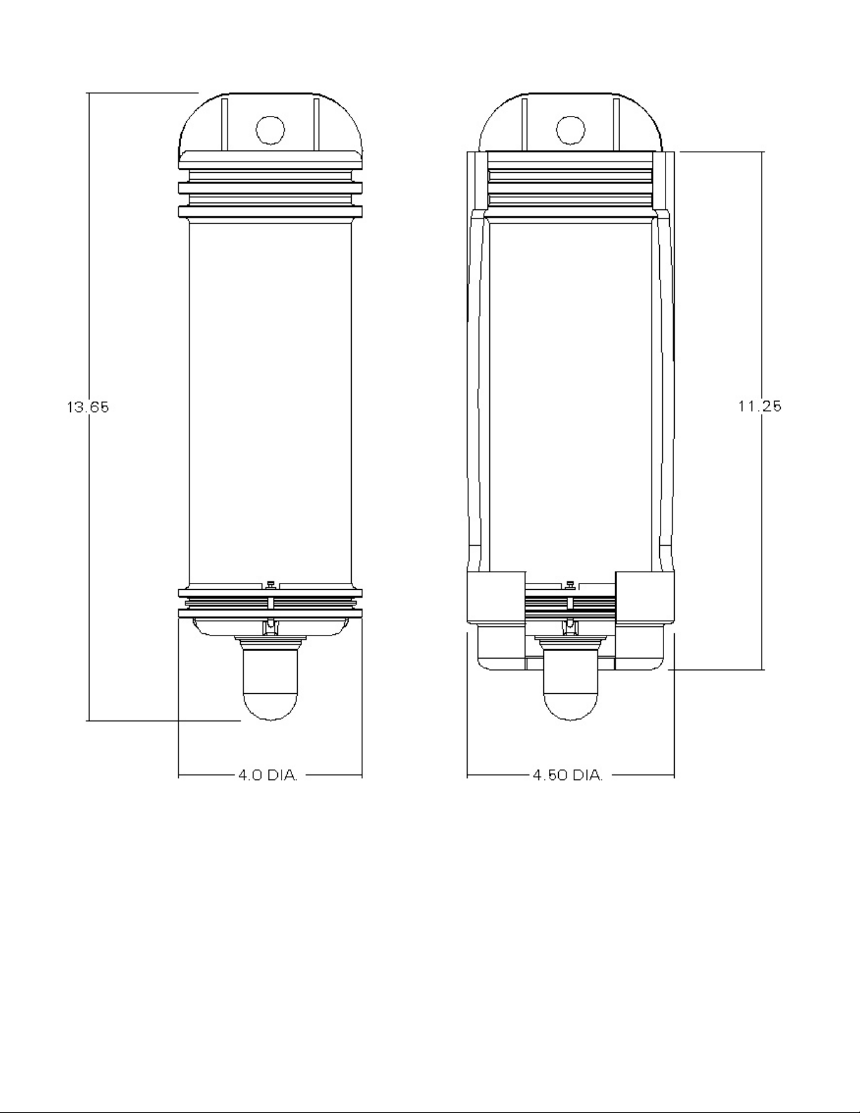
FIGURE 1
OUTLINE AND DIMENSIONAL SKETCH
7
Y1-03-0165 Rev. B
Page 9

FIGURE 2
INSTRUCTION PLATE LABEL
8
Y1-03-0165 Rev. B
Page 10

2. SECTION 2 - INSTALLATION
2.1 INSTALLATION PROCEDURES
The installation procedure requires that the mounting bracket be securely fastened in any convenient
location which would provide immediate access in the event of emergency situations.
Suitable length ¼ - 20 stainless screws should be used for mounting the bracket. Screw heads
should not protrude inside the bracket surface.
2.2 BATTERY INSTALLATION
The SM-2 is normally shipped from the factory without a battery. Follow disassembly instructions
in Section 3 of this Manual for battery installation. The SM-2 uses a standard 6 Volt lantern type
battery with screw terminals. A list of recommended batteries can be found on Page 1. Note
maximum allowable battery weight.
3.0 SECTION 3 - TESTING
3.1 OPERATION
The unit should be tested monthly. Remove the SM-2 from its bracket and invert it. The unit should
begin flashing immediately, at a rate of about one flash per second. Re-invert the unit after
ascertaining correct operation.
3.2 INSPECTION
Check the exterior of the unit for damage which might affect proper operation (damage to globe,
cracks in case, etc.) Check bracket security.
3.3 DISASSEMBLY
This will ordinarily be required only if testing shows that the light is malfunctioning, or if battery
replacement is required. Recommended interval for battery replacement is one year.
A. Hold the unit on a flat, firm surface, lens side up. Depress the top cap of the unit, by pushing
straight down on the top cap assembly, until the swivel locks may be turned outward, clear of the
cap.
B. Grip the light lens (using a clean cloth or gloves for a better grip on the smooth surface and to
avoid marring the lens surface) and pull upwards until the top cap is clear of the case.
C. Turn the unit on its side, open end slightly downwards, to allow the foam filler and battery to
slide out.
D. Disconnect the battery by unscrewing the terminals from the battery posts.
E. Replace the strobe module, if required, as follows:
1. Remove foam filler from strobe module, by sliding it off.
2. Slip foam spacer over new strobe module to seat in cap recess.
9
Y1-03-0165 Rev. B
Page 11

3. Inspect O-Ring seal for proper fit. Lubricate with silicone grease.
F. Replace the battery by securing the two terminals to the battery posts. Assure tightness.
NOTE: Connect black lead to center (-) post of battery. Connect red lead to outer (+) post of battery.
G. Check for proper operation by holding the top cap assembly vertical (light lens up). The unit
should flash about once each second. If the unit does not operate, check for proper battery
connection.
3.4 ASSEMBLY
Hold the case horizontally and slide the battery in, terminal end up (towards the open end of the
case).
Lubricate the top cap O-ring with silicone grease and insert the cap and foam spacer into the case.
Place the unit upright on a firm surface, and press the top cap assembly until the cap slips into the
case. Depress the cap until the locking swivels can seat into the provided recesses. Turn the locking
swivels, seat them into the cap recesses and remove pressure from the top to allow it to move
upwards and lock. Check unit operation.
CAUTION: Assure that the locking swivels are properly seated in the cap grooves. Rotate the
cap, if necessary, to assure proper seating of the swivels.
10
Y1-03-0165 Rev. B
Page 12

SM-2
PARTS LIST
ITEM DESCRIPTION PART NUMBER
1 Case Assembly A3-06-2295
*2 Case A1-18-1878
*3 Washer, 3 each A1-05-0659-3
*4 Locking Swivel, 3 each A1-17-1283
5 Battery Pad, Foam A1-18-0773
6 Battery Not Included
6 Volt Lantern Type
(See Tech. Data 2.17 for recommended battery)
7 Foam Filler A1-18-1877
8 O-Ring (Top Cap) A1-05-0001-64
9 Top Cap and Lens Tube Assembly 9021.1
10 Mounting Bracket 9438.1
11 Stainless Steel Bracket (Sold separately) 9566
12 6VST Battery Adapter (Sold separately) 9434
* Included with Item 1
REPAIR KIT DESCRIPTION PART NUMBER
SM-2 Retaining rings and locking swivels, 3 ea. 9286
O-ring and manual, 1 ea.
11
Y1-03-0165 Rev. B
Page 13

FIGURE 3
EXPLODED VIEW SM-2
12
Y1-03-0165 Rev. B
 Loading...