

Page 1

DESCRIPTION, OPERATION, INSTALLATION AND
MAINTENANCE MANUAL
FOR THE SLB 406 ELT
570-6700 Rev. B
This manual includes data for the equipment that follows:
Component Part No. Model No.
ARTEX PRODUCTS / ACR ELECTRONICS, INC
5757 Ravenswood Rd, Ft. Lauderdale, FL 33312
Cage Code: 60253
Page 1 of 43
Initial Issue DEC 19/2006
MAR 27/11
570-6700 Rev. B
Page 2

ARTEX PRODUCTS / ACR ELECTRONICS, INC
DESCRIPTION, OPERATION, INSTALLATION AND MAINTENANCE MANUAL
SLB 406 ELT
PROPRIETARY INFORMATION
This document contains proprietary information and such information may not be disclosed to
others for any purpose, nor used for manufacturing purposes without written permission from
ACR Electronics.
Information in this manual is subject to change without notice. ACR Electronics makes no
warranty, expressed or implied, with regard to this manual, including but not limited to any
implied warranties of merchantability, fitness for a particular purpose, and non-infringement. In
addition, ACR Electronics makes no warranty with regard to the documentation or data contained
herein. ACR Electronics is not liable in the event of incidentals, special, consequential, or any
other damages in connection with or arising from furnishing, performance, or use of this manual.
Reproduction of this publication or any portion thereof by any means is prohibited. For further
information contact Sales, ACR Electronics, 5757 Ravenswood Rd, Fort Lauderdale, FL 33312.
Telephone (954) 981-3333
AIRWORTHINESS LIMITATIONS
The Airworthiness limitations section is FAA approved and specifies inspections and other
maintenance required under 14 CFR§ 43.16 and 91.403, unless an alternative program has been
approved.
IMPORTANT NOTICE
ACR Electronics will be responsible for full distribution and revisions of ICA’s (Instructions for
Continued Airworthiness). For inquiries regarding the content and currency of this manual,
contact ACR Electronics, 5757 Ravenswood Rd, Fort Lauderdale, FL 33312.
Telephone (954) 981-3333
Page 2 of 43
MAR 27/11
570-6700 Rev. B
Initial Issue DEC 19/2006
Page 3
ARTEX PRODUCTS / ACR ELECTRONICS, INC
REVISION
CHANGE
DATE
REVISION
CHANGE
DATE
-
RELEASE
Dec 19/2006
- DCN 3078
Oct 02/2007
A
ECO 14756
Jul 29/2011
B ECO 15020
Mar 27/2012
DESCRIPTION, OPERATION, INSTALLATION AND MAINTENANCE MANUAL
SLB 406 ELT
RECORD OF REVISIONS
Page 3 of 43
MAR 27/11
570-6700 Rev. B
Initial Issue DEC 19/2006
Page 4
ARTEX PRODUCTS / ACR ELECTRONICS, INC
SERVICE
BULLETIN
NO
ISSUE
DATE
SUBJECT
MANUAL
REV NO
MANUAL
REV DATE
DESCRIPTION, OPERATION, INSTALLATION AND MAINTENANCE MANUAL
SLB 406 ELT
SERVICE BULLETIN LIST
Page 4 of 43
MAR 27/11
570-6700 Rev. B
Initial Issue DEC 19/2006
Page 5

ARTEX PRODUCTS / ACR ELECTRONICS, INC
DESCRIPTION, OPERATION, INSTALLATION AND MAINTENANCE MANUAL
SLB 406 ELT
THIS IS A BLANK PAGE
Page 5 of 43
MAR 27/11
570-6700 Rev. B
Initial Issue DEC 19/2006
Page 6

ARTEX PRODUCTS / ACR ELECTRONICS, INC
SUBJECT
PAGE
DATE
SUBJECT
PAGE
DATE
Title Page
1
Mar 27/12
Proprietary Information
2
Mar 27/12
Record of Revisions
3
Mar 27/12
Service Bulletin List
4
Mar 27/12
5 BLANK
List of Effective Pages
6
Mar 27/12
Table of Contents
7-8
Mar 27/12
Notices
9
Mar 27/12
Introduction
10
Mar 27/12
Description
11-14
Mar 27/12
Operation
15-19
Mar 27/12
Installation
20-24
Mar 27/12
Maintenance
25-33
Mar 27/12
Specifications
34-41
Mar 27/12
Index
42
Mar 27/12
DESCRIPTION, OPERATION, INSTALLATION AND MAINTENANCE MANUAL
SLB 406 ELT
LIST OF EFFECTIVE PAGES
Page 6 of 43
MAR 27/11
570-6700 Rev. B
Initial Issue DEC 19/2006
Page 7

ARTEX PRODUCTS / ACR ELECTRONICS, INC
DESCRIPTION, OPERATION, INSTALLATION AND MAINTENANCE MANUAL
SLB 406 ELT
TABLE OF CONTENTS
PROPRIETARY INFORMATION ............................................. 2
RECORD OF REVISIONS ............................................................ 3
SERVICE BULLETIN LIST ...................................................... 4
LIST OF EFFECTIVE PAGE ...................................................... 6
RECORD OF REVISIONS ........................................................ 6
Notices .................................................................................. 9
Warnings ............................................................................... 9
Introduction ........................................................................ 10
Application ................................................................................................ 10
Description .......................................................................... 11
Certification:.............................................................................................. 12
Other requirements ................................................................................ 12
Programming: ........................................................................................ 12
Cospas-Sarsat Overview ............................................................................. 13
Figure 2 - SLB 406 View .......................................................................... 14
Operation ............................................................................ 15
Introduction ........................................................................................... 15
Deployment ........................................................................................... 15
Figure 3 – ELT Deployment ..................................................................... 15
Figure 4 - Indicators and Buttons ............................................................ 16
Functions .................................................................................................. 17
Activation .............................................................................................. 17
Normal Operation ................................................................................... 18
406.028 MHz Transmission ..................................................................... 18
121.5 MHz Homing Transmissions ........................................................... 18
Deactivation ........................................................................................... 18
Self-Test ................................................................................................ 18
Installation .......................................................................... 20
TSO C126 Paragraph D Requirements: ........................................................ 20
Parts List: .................................................................................................. 20
FAA Form 337 ........................................................................................... 21
Radio Station License ................................................................................. 21
Registration ............................................................................................... 21
International Beacon Registration Database ................................................ 24
Maintenance ........................................................................ 25
Periodic maintenance ................................................................................. 25
Battery replacement ............................................................................... 26
Figure 6 - ELT Battery Installation/Removal Exploded View ....................... 26
Page 7 of 43
MAR 27/11
570-6700 Rev. B
Initial Issue DEC 19/2006
Page 8

ARTEX PRODUCTS / ACR ELECTRONICS, INC
DESCRIPTION, OPERATION, INSTALLATION AND MAINTENANCE MANUAL
SLB 406 ELT
Verification of Digital Message ................................................................. 28
Perform Transmitter Tests (Self Test) ...................................................... 29
Figure 7 - Test Button and LED Indicators ............................................... 29
Lanyard Deployment Test ....................................................................... 31
Figure 8 – Lanyard Deployment Test ....................................................... 31
Logbook Entry ........................................................................................ 33
Verify Registration .................................................................................. 33
Specifications ...................................................................... 34
Summary of Minimum Requirements ........................................................... 35
Operating Frequencies ............................................................................ 35
Output Power ......................................................................................... 35
Activation .............................................................................................. 35
Temperature .......................................................................................... 35
Fire Resistance ....................................................................................... 35
Input Power ........................................................................................... 35
Mechanical Characteristics ...................................................................... 35
Electrical Characteristics ......................................................................... 36
Software ................................................................................................ 36
Other Specifications ................................................................................ 36
Weight Table ............................................................................................. 37
Electrical Load Analysis (Current Draw) Table .............................................. 37
452-0129 Battery Pack ............................................................................... 38
182-0250 Auto Activation Lanyard .............................................................. 39
SLB 406 Overall Dimensions ....................................................................... 40
SLB 406 Series DO-160D Environmental Qualification Form .......................... 41
INDEX ....................................................................................................... 42
Page 8 of 43
MAR 27/11
570-6700 Rev. B
Initial Issue DEC 19/2006
Page 9

ARTEX PRODUCTS / ACR ELECTRONICS, INC
DESCRIPTION, OPERATION, INSTALLATION AND MAINTENANCE MANUAL
SLB 406 ELT
Notices
1. Information contained in this manual is subject to regular updates and changes.
Users under multi-unit contracts will be notified of these updates and changes as
they occur.
2. Complying with all applicable copyright laws is the responsibility of the user. Without
limiting the rights under copyright, no part of this document may be reproduced,
stored in a retrieval system, or transmitted in any form or by any means including
but not limited to, electronic, mechanical, photocopying, recording, or otherwise, or
for any purpose, without the written permission of Artex Products / ACR Electronics,
Inc. (hereafter Artex). This written permission shall be granted to military services
and/or government agencies as part of a multi-unit contract.
3. Artex may have patents, patent applications, trademarks, copyrights, or other
intellectual property rights covering subject matter in this document. Except as
expressly provided in any written license agreement from Artex, the furnishing of
this document does not provide license to these patents, trademarks, copyrights, or
other intellectual property.
Warnings
1. Never short-circuit the unit battery.
2. Do not expose this beacon to temperatures >85° C for a prolonged period -
overheating of the lithium battery of the unit causes a pressure increase and a risk
of bursting and explosion.
3. Lithium batteries are classified as hazardous goods, appropriate precautions must be
taken when transporting beacons and battery packs.
4. The SLB 406 should be activated only in an actual emergency situation, because its
activation triggers a search and rescue operation.
Page 9 of 43
MAR 27/11
570-6700 Rev. B
Initial Issue DEC 19/2006
Page 10

ARTEX PRODUCTS / ACR ELECTRONICS, INC
DESCRIPTION, OPERATION, INSTALLATION AND MAINTENANCE MANUAL
SLB 406 ELT
Introduction
This manual contains all necessary information to describe, operate, install and maintain
the SLB 406 ELT. The manual contains all necessary information to ensure continued
airworthiness. Artex does not generate Aircraft Flight Manuals (AFM) or supplements
thereof; these documents are the responsibility of the aircraft operator as required by
FAR 121 subpart G §121.131 through §121.141.
Information presented in this manual is accurate at time of printing but is subject to
change. Refer to the ACR products web site at www.acrartex.com for the latest
information and any updates to this manual.
Web links provided in this manual were accurate at time of printing but are subject to
change.
Regulatory references are aimed at FAA requirements. Consult your national aviation
authority for requirements if you are located outside of the US.
Application
This manual constitutes FAA approved data as described in AC 43.9-1E, paragraph
(h)(2) and AC 43-210, chapter 2, paragraph 201(a)(6) for major alterations. Not all
installations are “major”; consult an FAA designee or regional office for clarification.
The conditions and tests required for TSO approval of this article are minimum
performance standards. It is the responsibility of those desiring to install this article
either on a specific type or class of aircraft to determine that the aircraft installation
conditions are within the TSO standards. The article may be installed only if further
evaluation by the applicant documents an acceptable installation and it is approved by
the Administrator.
Page 10 of 43
MAR 27/11
570-6700 Rev. B
Initial Issue DEC 19/2006
Page 11

ARTEX PRODUCTS / ACR ELECTRONICS, INC
DESCRIPTION, OPERATION, INSTALLATION AND MAINTENANCE MANUAL
SLB 406 ELT
Description
The SLB 406 (Survivor Locator Beacon) is a Type S (Survival) Emergency Locator
Transmitter that provides world-wide alerting in emergency situations via a network of
satellites of the Cospas-Sarsat distress alerting system. This system enables the location,
nationality, unit serial number, and user specific registration data of the personal locator
beacon to be immediately identified with the receipt of the alert.
The SLB 406 was developed to meet demanding environmental standards for individual’s
onboard aircraft, on land and at sea. The beacon is made of tough poly-carbonate
plastic, and is designed to withstand the rigors of severe outdoor use. The flip face
cover (see Figure 4) protects the buttons and indicators against damage and inadvertent
activation. It is fully waterproof to 10m, operable over the -20°C to +55°C temperature
range. This ensures that should a survivor need help, the message will get through.
The SLB 406 user interface is intuitive and easy to use, no matter the condition of the
survivor. The SLB 406 can be used equally well with either the right or left hand, with
buttons large enough to be operated while wearing gloves. Activating the beacon is
simple and can be done with one hand, or can be activated automatically upon life vest
inflation. For manual activation, the survivor simply flips open the face cover and
presses the activate button, which immediately activates the beacon. Visual indications
of beacon activation is provided. The beacon can be switched off by the rescue crew
after the survivors have been rescued or by the survivors if multiple beacons are active.
A beacon that has been turned off can be reactivated simply by pressing the activate
button. The safety lanyard can be attached to the user’s equipment to ensure that the
beacon is not lost or otherwise separated from the person in distress.
Examples of the information that can be contained in that message are shown below:
Serial Number of the transmitter or Aircraft ID (24-Bit Address or Tail Number)
Country Code
Cospas/Sarsat ID Code (Serialized Only)
The 406.028 MHz transmitter with the supplied battery will operate for 24 hours, and
then shut down automatically. The 121.5 MHz transmitter will continue to operate until
the unit has exhausted the battery power which will be greater than 50 hours.
Page 11 of 43
MAR 27/11
570-6700 Rev. B
Initial Issue DEC 19/2006
Page 12

ARTEX PRODUCTS / ACR ELECTRONICS, INC
DESCRIPTION, OPERATION, INSTALLATION AND MAINTENANCE MANUAL
SLB 406 ELT
Certification:
The SLB 406 has been certified to the following:
TSO C126
TSO C91a in the 121.5/406 MHz configuration as referenced in TSO-C126,
paragraph (e).
FAR Part 91 – mandatory automatic ELT requirements
Cospas-Sarsat T.001, Type Approval Certificate #148
47 CFR Part 87 (FCC requirements) Note: Per FCC regulations 47 CFR § 2.902, the
ELT is tested per “Verification” method, the FCC does not issue certificates for ELT’s.
The FCC identifier grantee code for Artex is H4K.
Other requirements
The SLB 406 was not tested for other specifications beyond the requirements of TSO
C126. Compliance with additional FAR’s (such as FAR 25) are the responsibility of the
installer as required for installation approval.
The US Federal Aviation Regulations (FAR’s) are available at:
http://www.airweb.faa.gov/Regulatory_and_Guidance_Library/rgFAR.nsf/MainFrame?Op
enFrameSet
NOTE: For use outside of the US, contact your local civil aviation authority for ELT
requirements.
Programming:
The SLB 406 supports the following Protocols:
Aviation ELT / Tail Number (Short)
Serial User/ Aircraft 24 Bit Addr (Short)
Serial User / Aircraft 24 Bit / National (Short)
Serial User / ELT / COSPAS (Short)
Serial User / ELT / National USA (Short)
Serial User / Aircraft Operator (Short)
For a complete discussion of ELT programming protocols please see Cospas-Sarsat
Documents G.005 and T.001 available at www.cospas-sarsat.org.
The United States accepts all of the above listed protocols. For use outside of the US,
contact your local civil aviation authority for accepted or required programming
protocols. The desired protocol must be provided to Artex at time of ordering.
NOTE: The SLB 406 is not currently configured for use with Location Protocols.
Page 12 of 43
MAR 27/11
570-6700 Rev. B
Initial Issue DEC 19/2006
Page 13
ARTEX PRODUCTS / ACR ELECTRONICS, INC
DESCRIPTION, OPERATION, INSTALLATION AND MAINTENANCE MANUAL
SLB 406 ELT
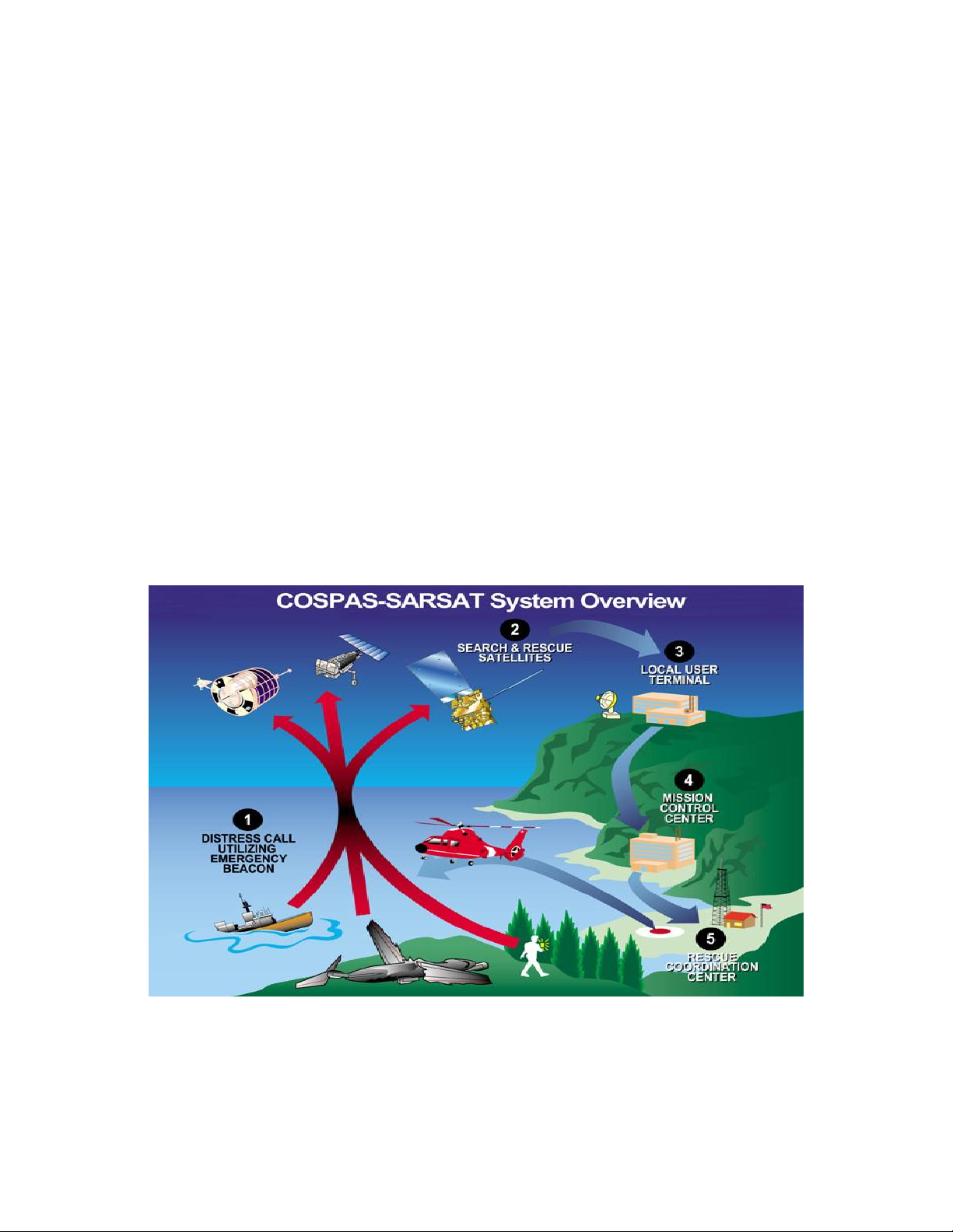
Cospas-Sarsat Overview
Cospas-Sarsat is an international, humanitarian search and rescue system that uses
satellites to detect and locate emergency beacons carried by ships, aircraft, and
individuals. The system consists of a network of satellites, ground stations, mission
control centers, and rescue coordination centers.
When a 406 MHz emergency beacon is activated, the signal is received by a satellite and
relayed to the nearest available ground station. The ground station, called a Local User
Terminal (LUT), processes the signal and calculates the position from which it originated
using the Doppler Shift process. This position is transmitted to a mission control center
(MCC) where it is joined with identification data and other information on that beacon.
The MCC then transmits an alert message to the appropriate rescue coordination center
based on the geographic location of the beacon. If the location of the beacon is in
another country's area of responsibility, then the alert is transmitted to that country's
assigned MCC.
On average, from the time a 406 MHz emergency beacon is activated it takes 8-10
minutes for the alert message and accompanying identification data to arrive at the
appropriate rescue coordination center. The Cospas-Sarsat system provides the
capability for protecting lives. With a 406 MHz beacon, a distress message can be sent
to the appropriate authorities from anywhere on Earth 24 hours a day, 365 days a year.
Figure 1 – Cospas-Sarsat Overview
Page 13 of 43
MAR 27/11
570-6700 Rev. B
Initial Issue DEC 19/2006
Page 14

ARTEX PRODUCTS / ACR ELECTRONICS, INC
DESCRIPTION, OPERATION, INSTALLATION AND MAINTENANCE MANUAL
Figure 2 - SLB 406 View
SLB 406 ELT
Warning:
The ELT is NOT buoyant, and must be attached to a
floatation device when in water environments.
Failure to observe this warning may cause the ELT to fail
when it is critical for it to operate. Such failure may cause
loss of life.
Page 14 of 43
MAR 27/11
570-6700 Rev. B
Initial Issue DEC 19/2006
Page 15

ARTEX PRODUCTS / ACR ELECTRONICS, INC
DESCRIPTION, OPERATION, INSTALLATION AND MAINTENANCE MANUAL
SLB 406 ELT
Operation
Introduction
The SLB 406 is designed to provide world-wide alerting in emergency situations via the
Cospas-Sarsat System. The SLB 406 operates on two frequencies simultaneously – 406
MHz as the alerting frequency for the Cospas-Sarsat satellite system, 121.5 MHz as the
civilian homing frequency to aid SAR responders. Following is a description of the
operating instructions and functions of the SLB 406.
Deployment
In the storage configuration, the antenna is wrapped around the chassis of the ELT and
held in place with a snap on the Activation Lanyard. To deploy the antenna, simply
unsnap and pull away from the Activation Lanyard. The antenna may be rotated for best
position. The SLB 406 will provide the best transmission characteristics when it is placed
on a flat surface with the antenna oriented vertically.
The SLB 406 can also be held in the hand with the antenna oriented vertically. See
Figure 3 below:
Figure 3 – ELT Deployment
Page 15 of 43
MAR 27/11
570-6700 Rev. B
Initial Issue DEC 19/2006
Page 16

ARTEX PRODUCTS / ACR ELECTRONICS, INC
DESCRIPTION, OPERATION, INSTALLATION AND MAINTENANCE MANUAL
SLB 406 ELT
Indicators and Buttons
Figure 4 displays the functional buttons and LED indicators on the faceplate of the SLB
406.
Figure 4 - Indicators and Buttons
ACTIVATE: Press and hold for approximately 2 seconds to activate the beacon.
Page 16 of 43
MAR 27/11
570-6700 Rev. B
Initial Issue DEC 19/2006
Page 17

ARTEX PRODUCTS / ACR ELECTRONICS, INC
DESCRIPTION, OPERATION, INSTALLATION AND MAINTENANCE MANUAL
SLB 406 ELT
THIS TRANSMITTER IS AUTHORIZED FOR USE ONLY DURING SITUATIONS OF GRAVE
AND IMMINENT DANGER, WHEN ALL OTHER MEANS OF SELF RESCUE HAVE BEEN
EXHAUSTED.
OFF: Press for approximately 2 seconds to turn SLB off.
TEST: Press for approximately 2 seconds to initiate Self Test operations.
XMIT: LED flashes Red once every two seconds indicating Normal Operation.
During an actual 406 MHz transmission (nominally every 50 seconds), the LED stays Red
for the full 406 MHz pulse transmission –approximately one second.
PASS: LED flashes green for 60 seconds indicating a successful Self Test
operation.
FAIL: LED flashes red for 60 seconds indicating a failed Self Test operation.
Functions
Activation
The SLB 406 can be activated in two modes: 1) Automatic Activation, and 2) Manual
Activation. The Automatic Activation mode requires the use of the automatic activation
lanyard/Activation Lanyard attached to a life raft or the inflatable portion of a life vest.
In this mode the beacon will be automatically activated upon life vest/raft inflation
without any user action. Beacon activation occurs when the activation lanyard is
separated from the beacon. When the beacon is activated, the red XMIT LED will
illuminate for approximately one second to acknowledge. To activate the SLB 406 in the
Manual Activation mode, press the ACTIVATE button for approximately two seconds
until the red XMIT light illuminates. When the beacon is activated, the red XMIT LED will
illuminate for approximately one second to acknowledge. Figure 5 shows the protective
faceplate of the SLB 406 which protects the buttons from inadvertent activation or
turnoff.
Figure 5 – Protective Face Plate
Page 17 of 43
MAR 27/11
570-6700 Rev. B
Initial Issue DEC 19/2006
Page 18

ARTEX PRODUCTS / ACR ELECTRONICS, INC
DESCRIPTION, OPERATION, INSTALLATION AND MAINTENANCE MANUAL
SLB 406 ELT
Normal Operation
After this initial Activate illumination, the red XMIT LED will blink every two seconds.
406.028 MHz Transmission
The 406.028 MHz transmission occurs approximately once every 50 seconds. This
transmission includes coded information including the beacon’s unique ID. During the
transmission, the red XMIT LED lights for the duration of the transmit pulse. There is a
50 second delay in the initial transmission after activation as required by Cospas-Sarsat.
The purpose of this delay is to minimize the occurrence of false alerts, as a person has
50 seconds to turn off a beacon that was mistakenly activated.
121.5 MHz Homing Transmissions
These homing transmissions operate continuously while the beacon is activated except
during the 406 MHz pulse transmissions.
Deactivation
The SLB 406 can be deactivated from either the Automatic or Manual Activation modes
by pressing and holding the OFF button for approximately two seconds. The red XMIT
LED will illuminate for 1 second prior to turning off to acknowledge the deactivation. The
red XMIT LED will stop blinking when the beacon is turned off. The SLB 406 can be
turned back on by simply pressing the ACTIVATE button for approximately two seconds.
If the beacon is deactivated without the Activation Lanyard installed, the batteries will
continue to discharge.
Self-Test
Self Tests are to be conducted only by second line maintenance
To conduct a self-test of the SLB 406, press the TEST button and hold for approximately
two seconds. The red XMIT LED will illuminate for approximately one second to
acknowledge.
The PASS LED (green) and the FAIL LED (red) will then illuminate together for
approximately 1 second to test these LEDs.
During the self-test process, the XMIT LED flashes in the following progression:
The XMIT LED illuminates solidly for approximately 1 second during the 406.028 MHz
and 121.5 MHz pulse tests.
Page 18 of 43
MAR 27/11
570-6700 Rev. B
Initial Issue DEC 19/2006
Page 19

ARTEX PRODUCTS / ACR ELECTRONICS, INC
DESCRIPTION, OPERATION, INSTALLATION AND MAINTENANCE MANUAL
SLB 406 ELT
The XMIT LEDs flashes simultaneously for approximately 1.5 seconds during the
121.5MHz modulation test.
Following the test the PASS LED will flash at a rate of twice per second for a total period
of 60 seconds to indicate that the SLB 406 is fully functional. Alternatively, the FAIL LED
will flash at a rate of twice per second for a total period of 60 seconds to indicate that
the SLB 406 has malfunctioned. The unit then shuts off.
Page 19 of 43
MAR 27/11
570-6700 Rev. B
Initial Issue DEC 19/2006
Page 20

ARTEX PRODUCTS / ACR ELECTRONICS, INC
DESCRIPTION, OPERATION, INSTALLATION AND MAINTENANCE MANUAL
SLB 406 ELT
Installation
The ELT intended application is to be installed as part of a slide raft emergency system
used in commercial aircraft or other life raft application. Design of the ELT was based on
the assumption that the ELT would be inserted in a pocket in the raft. For automatic
activation, connect the Auto Activation Lanyard (as shown on page 39) to the raft such
that inflation of the raft will pull the Lanyard from the ELT.
Note: Installation of an Automatic Fixed “Type AF” ELT may also be required; contact
you local Flight Standards District Office (or applicable civil aviation authority
representative) if in doubt.
TSO C126 Paragraph D Requirements:
“The conditions and tests required for TSO approval of this article are minimum
performance standards. It is the responsibility of those desiring to install this article on a
specific type or class of aircraft to determine that the aircraft installation conditions are
within the TSO standards. The article may be installed only if further evaluation by the
applicant documents an acceptable installation and it is approved by the administrator.”
Note: Aircraft manufacturers may also have guidance on ELT installation; refer to and
follow any applicable Type Approval or STC data for your aircraft. If located outside of the
US, follow all applicable regulations for your national authority.
Parts List:
Included in standard kit:
The SLB 406 is offered as a complete kit. Please review the components included in a base
kit. The following parts should be included. Contact Artex Aircraft Supplies if shortages are
found.
ELT P/N 453-6700 (completely assembled, includes Battery Pack, Antenna, Safety
Lanyard and Activation Lanyard)
Battery Pack, Artex P/N 452-0129 (Li/SO2) (included with ELT above)
Screw, 6-32 x ¾, Socket SS, Artex P/N 209-0001 (included with ELT above, used to
attach Battery Pack)
Activation Lanyard, Artex P/N 182-0250 (included with ELT above)
Manual, Artex P/N 570-6700 – also available free for download at www.acrartex.com
All of the above listed parts (except Antenna and Safety Lanyard) may be purchased
separately as line replaceable parts. Contact Artex at 1-800-432-0227 for details, pricing and
availability.
Page 20 of 43
MAR 27/11
570-6700 Rev. B
Initial Issue DEC 19/2006
Page 21

ARTEX PRODUCTS / ACR ELECTRONICS, INC
DESCRIPTION, OPERATION, INSTALLATION AND MAINTENANCE MANUAL
SLB 406 ELT
Note: Removal of the Antenna is not permitted; unit must be return to Artex for repair or
replacement of the antenna.
FAA Form 337
For installations that are considered a “major alteration”, an FAA Form 337 will be
required. Information regarding the completion of Form 337 can be found in Advisory
Circular AC 43.9-1E. This Manual constitutes FAA approved data as described in AC
43.9-1E, paragraph (h)(2) and AC 43-210, chapter 2, paragraph 201(a)(6) for major
alterations. Not all installations are “major”; consult an FAA designee or regional office
for clarification. Generally, the installation of the SLB 406 will not require a Form 337 but
contact you local Flight Standards District Office if in doubt.
Radio Station License
A Radio Station License is not required by the FCC for Emergency Locator Transmitters
(ELTs). See the FCC web site at http://wireless.fcc.gov/aviation/fctsht4.html which
states:
“On October 26, 1996, the FCC released a Report and Order in WT Docket No. 96-82,
FCC 96-421 eliminating the individual licensing requirement for all aircraft operating
domestically. This means that you do not need a license to operate a two-way VHF
radio, radar, or ELT aboard aircraft operating domestically. All other aircraft radio
stations must be licensed by the FCC either individually or by fleet.”
FCC Form 605 which replaced FCC Form 404 in 1999 is not required for ELTs.
For more information, contact the FCC at:
Federal Communications Commission
445 12th Street SW
Washington, DC 20554
1-888-CALL-FCC (1-888-225-5322)
E-mail: fccinfo@fcc.gov
For radio station license information outside of the Unites States, contact you national
radio communications authority for assistance.
Registration
REGISTRATION FORMS (OR LINKS TO THEM ) ARE PROVIDED ON THE ARTEX
WEB SITE AT www.acrartex.com .
When a 406 MHz ELT is installed in an aircraft, it is imperative that the aircraft owner
register the ELT. In the United States the National Oceanic and Atmospheric
Administration (NOAA) is the registration agency. Each 406 MHz ELT contains a unique
identification code that is transmitted to the satellite. This helps the “Rescue
Page 21 of 43
MAR 27/11
570-6700 Rev. B
Initial Issue DEC 19/2006
Page 22

ARTEX PRODUCTS / ACR ELECTRONICS, INC
DESCRIPTION, OPERATION, INSTALLATION AND MAINTENANCE MANUAL
SLB 406 ELT
Coordination Center” (RCC) determine whether an emergency actually has occurred. The
unique identification permits accessing a data base. In the United States the data base
contains the following:
Owner’s Name
Address
Telephone Number
Aircraft Type
Aircraft Registration Number
This data facilitates inquiries as to the whereabouts of the aircraft, the existence of a
flight plan and so forth. The above information should be kept up to date, with any
changes to the data corrected (i.e. change of address, phone numbers, etc.).
Important Notice -
The information you furnish is mandatory and is intended to assist search and rescue
teams in locating you or your craft in the event of beacon activation. The information
will be provided to the United States Coast Guard, United States Air Force, and other
Search and Rescue (SAR) teams as appropriate in the event of beacon activation. It will
also be used to conserve SAR resources by helping to eliminate false alert deployments,
e.g. an inadvertent activation can be resolved with a phone call.
Failure to register, re-register (which occurs every two years) or to notify NOAA of a
change in the status for a 406 MHz beacon could result in penalties and/or fines being
issued to the owner. An owner is required to notify NOAA of any changes to the
registration information. Please note, due to the critical need for up-to-date registration
information, NOAA will update the database accordingly if a beacon owner’s registration
has expired and credible information is provided from SAR sources. NOAA will also seek
information from other databases to update and/or complement the existing information
for a beacon registration. Solicitation of this information is authorized by Parts 80, 87,
and 95 of Title 47 of the U.S. Code of Federal Regulations (CFRs).
Please Read Before Completing Registration
There is no charge for beacon registration. This is a service provided by the
U.S. Government.
All online registrations will be entered into the National 406 MHz Beacon Registration
Database on the same day of entry. Registration forms received via the postal mail
service will be entered into the National 406 MHz Beacon Registration Database within 2
business days of receipt. For online registrations, a letter with an attached registration
information sheet will be sent immediately via e-mail or fax (if provided), or via postal
mail within two weeks. Once your registration confirmation is received, please review all
information. Any changes or updates to your registration information can be done via
the internet, fax, e-mail or postal mail. If you do not receive your registration
Page 22 of 43
MAR 27/11
570-6700 Rev. B
Initial Issue DEC 19/2006
Page 23

ARTEX PRODUCTS / ACR ELECTRONICS, INC
DESCRIPTION, OPERATION, INSTALLATION AND MAINTENANCE MANUAL
SLB 406 ELT
confirmation from NOAA on the same day you submit it over the internet or within two
weeks if you submit it by postal mail, please call NOAA toll-free at:
1-888-212-SAVE (7283) or 301-457-5678 for assistance.
After initial registration (or re-registration) you will receive a NOAA Proof of Registration
Decal by postal mail. It is required that you affix the registration decal to your beacon. If
for some reason you do not receive the registration decal within two weeks, please call
NOAA at the above number for assistance. Registration forms can be found on the
NOAA SARSAT website at: www.sarsat.noaa.gov or at:
www.beaconregistration.noaa.gov.
Although the information provided will become a matter of public record, there is no
intent to circulate the data furnished beyond its intended purpose, i.e., to assist SAR
forces in carrying out their mission of rescue assistance and false alert abatement.
Public reporting burden for the collection of this information is estimated to average 15
minutes per response, including the time for reviewing instructions, searching existing
data sources, gathering and maintaining the data needed, and completing and reviewing
the collection of information. Comments regarding this burden estimate or any other
aspect of this collection of information, including suggestions for reducing this burden
should be sent to:
SARSAT Beacon Registration NOAA
NSOF, E/SP053
4231 Suitland Road
Suitland, MD 20746
Or call: 1-888-212-SAVE (7283) or 301-457-5678
WARNING: If the ELT is moved to a different aircraft than which it was originally
registered with, the ELT must be re-registered and the product label re-marked to
indicate the new programming and/or new country of registry.
NOTICE: FOR ELTS THAT WILL HAVE A COUNTRY OF REGISTRATION OTHER
THAN USA, PLEASE CONTACT THE APPROPRIATE CIVIL AVIATION AUTHORITY
IN THAT COUNTRY FOR GUIDELINES AND DOCUMENTATION NEEDED TO
ASSURE PROPER REGISTRATION
Refer to Cospas/Sarsat Documents G.005 and S.007 for information regarding ELT
programming and registration, available at www.cospas-sarsat.org.
Page 23 of 43
MAR 27/11
570-6700 Rev. B
Initial Issue DEC 19/2006
Page 24

ARTEX PRODUCTS / ACR ELECTRONICS, INC
DESCRIPTION, OPERATION, INSTALLATION AND MAINTENANCE MANUAL
SLB 406 ELT
International Beacon Registration Database
Effective January 16, 2006, Cospas-Sarsat implemented an International Beacon
Registration Database (IBRD) to allow 406 MHz beacon owners the ability to register
their beacon where no national registration database exists via the internet at
www.406registration.com. There is no charge for this service.
Beacons registered with the IRBD must conform to any national regulations regarding
their beacon where no national registration database exists via the internet at
www.406registration.com. There is no charge for this service.
Beacons registered with the IRBD must conform to any national regulations regarding
ELT programming. Cospas-Sarsat does not provide guidance on the specific coding
options that are accepted by individual national authorities or administrations.
The IRBD cannot accept registrations for countries that have informed Cospas-Sarsat
that they operate national registries.
The minimum information required to register a beacon in the IBRD is:
Beacon Hexadecimal ID
Owner name and phone number
Emergency contact name and phone number
Vehicle Type (Selectable from a menu)
Vehicle Name, MMSI, Call sign or identification number
Links to all referenced web sites are available at www.acrartex.com.
Page 24 of 43
MAR 27/11
570-6700 Rev. B
Initial Issue DEC 19/2006
Page 25

ARTEX PRODUCTS / ACR ELECTRONICS, INC
DESCRIPTION, OPERATION, INSTALLATION AND MAINTENANCE MANUAL
SLB 406 ELT
Maintenance
This section describes minimum continued airworthiness requirements that can be
performed by the aircraft owner/operator. Additional maintenance must be performed
by an authorized Artex Repair Station.
Periodic maintenance
In the United States, minimum maintenance requirements for ELTs are stated in FAR
91.207 paragraph (d):
(d) Each emergency locator transmitter required by paragraph (a) of this
section must be inspected within 12 calendar months after the last inspection
for-(1) Proper installation;
(2) Battery corrosion;
(3) Operation of the controls and crash sensor; and
(4) The presence of a sufficient signal radiated from its antenna.
To ensure continued reliability and airworthiness, your ELT must be inspected for
damage and wear caused by age, exposed elements, vibration, etc. Inspections are also
to take place annually per FAR Part 91.409. FAR 43, Appendix D(i) states in part that
each person performing an annual or 100-hour inspection shall inspect the following
components of (the ELT):
(1) (ELT unit and mount) for improper installation and insecure mounting.
(2) Wiring and conduits - for improper routing, insecure mounting, and obvious defects.
(3) Bonding and shielding - for improper installation and poor condition.
(4) Antenna, including trailing antenna-for poor condition, insecure mounting, and
improper operation.
NOTE: All references to maintenance requirements for the United States shall also apply
to all ELT users outside of the US unless otherwise required by the installer / aircraft
maintenance procedures or the relevant national regulations.
NOTE:
All references to test equipment are generic; Artex makes no specific
equipment references (by manufacturer, etc). All tests described herein must be
performed by qualified personnel that are familiar with test equipment as well as
the specifications and parameters described.
Page 25 of 43
MAR 27/11
570-6700 Rev. B
Initial Issue DEC 19/2006
Page 26

ARTEX PRODUCTS / ACR ELECTRONICS, INC
DESCRIPTION, OPERATION, INSTALLATION AND MAINTENANCE MANUAL
SLB 406 ELT
Battery replacement
To remove battery, perform the following steps:
1) Remove SLB 406 from storage
2) Unfasten the Antenna from the Velcro on the Activation Lanyard
3) Remove the 4 x 6-32 hex head cap screws that attach the top Transmitter Assembly
to the Battery Pack
4) Disconnect Battery connector (this is a very short harness)
Verify the battery expiration date. If the battery pack has not expired it may be
reinstalled. The battery pack must be replaced with a new one:
After use in an emergency
When the transmitter has been in use for more than 1 cumulative hour
After an inadvertent activation of unknown duration
On or before the battery replacement (expiration) date
To re-install or replace the Battery Pack perform the following steps:
1) Plug in Battery connector to bottom of Transmitter Assembly
2) Assemble Battery Pack to Transmitter Assembly using the 4 x 6-32 hex head cap
screws, evenly torque to 9 in lbs (1 Nm)
3) Wrap Antenna around Battery Pack and snap into place and position onto Velcro
patch that is on the Activation Lanyard
Note: Replacement battery packs are provided with a fresh gasket, be sure to discard
the old gasket with the old battery pack if replacing the battery pack.
APPROVED BATTERIES AVAILABLE FROM ARTEX OR ANY ARTEX DEALER, OR:
ACR Electronics, Inc
5757 Ravenswood Rd
Fort Lauderdale, FL 33312
(954) 981-3333, FAX (954) 983-5087
web site: www.acrartex.com
Figure 6 - ELT Battery Installation/Removal Exploded View
Page 26 of 43
MAR 27/11
570-6700 Rev. B
Initial Issue DEC 19/2006
Page 27

ARTEX PRODUCTS / ACR ELECTRONICS, INC
DESCRIPTION, OPERATION, INSTALLATION AND MAINTENANCE MANUAL
SLB 406 ELT
Page 27 of 43
MAR 27/11
570-6700 Rev. B
Initial Issue DEC 19/2006
Page 28

ARTEX PRODUCTS / ACR ELECTRONICS, INC
DESCRIPTION, OPERATION, INSTALLATION AND MAINTENANCE MANUAL
Verification of Digital Message
SLB 406 ELT
NOTE:
This test is not mandatory per FAR 91.207(d) however Artex strongly
recommends that it be performed as part of annual maintenance.
Verify the 406 MHz digital message using a test set capable of receiving and decoding
the message. Artex suggests the ELT Test Set (ETS) P/N 453-1000. Contact your local
Artex dealer for availability of the ETS or call Artex direct at 1-800-432-0227. Other
beacon testers can be used for the digital message verification. Follow instructions
provided with the test set.
Realize that the ARTEX 406 MHz ELT transmits a 406 MHz message upon reset, which is
encoded such that it will be ignored by the SAR satellite system. This 15-digit number is
used to register the ELT with the appropriate 406 MHz ELT registration authority. In the
US, the National Oceanic and Atmospheric Administration (NOAA) maintains the
database of registered ELT’s.
To verify the digital message, perform the following steps:
1. Perform all necessary steps to prepare Test Set to receive 406 MHz signal including
(but not limited to) turning on power, activating program or any other steps required for
the particular Test Set being used.
2. Perform the Installed Transmitter Test “self test” as described on page 29.
3. Watch the screen on the Test Set to ensure that a message has been received.
Repeat “self test” if necessary.
4. View message, ensure that all applicable information is correct (country code, aircraft
ID, etc.).
5. The 15 digit ID hex ID (for example “ADC6492640D3411F”) should match what is
shown on the ELT product label. This is the 15 digit hex ID (Unique Identification
Number or “UIN”) that is used to register the ELT.
The test message contains all the information contained in the actual distress
message except position data and there is a special digital test prefix that
tells the COSPAS/SARSAT satellites to ignore the message.
Page 28 of 43
MAR 27/11
570-6700 Rev. B
Initial Issue DEC 19/2006
Page 29

ARTEX PRODUCTS / ACR ELECTRONICS, INC
DESCRIPTION, OPERATION, INSTALLATION AND MAINTENANCE MANUAL
SLB 406 ELT
Perform Transmitter Tests (Self Test)
Self tests must be performed outside of metallic enclosures and at least 2 meters away
from large metallic surfaces which may reflect electromagnetic waves. If restrictions are
not observed it is possible that self test may report failure when the beacon is operating
properly.
Following are step-by-step instructions for performing the field tests.
1) Examine the SLB 406 closely for signs of physical damage including cracked or
punctured housing, cracked or broken face plate or damaged antenna.
Note: The antenna is not intended to be removed from the ELT by the user.
2) Perform Self-test by pressing the self-test button (see Figure 7) for two seconds, then
releasing the button.
3) Observe the red XMIT LED. It will light up for one second as acknowledgement.
4) The Pass LED and the Fail LED will then light up together for one second. After this,
at different stages of the test, the other LEDs glow steadily or flash depending on the
particular self-test being performed.
5) Check for Pass/ Fail. After five seconds, either the ‘Pass’ or the ‘Fail’ LED will start
flashing for sixty seconds, the green LED for pass and the red LED for fail.
Figure 7 - Test Button and LED Indicators
Page 29 of 43
MAR 27/11
570-6700 Rev. B
Initial Issue DEC 19/2006
Page 30

ARTEX PRODUCTS / ACR ELECTRONICS, INC
DESCRIPTION, OPERATION, INSTALLATION AND MAINTENANCE MANUAL
SLB 406 ELT
The unit will shut off automatically at the end of self-test. If the self-test passes (that is
the green PASS LED flashes for 60 seconds) no further tests are required.
If the self-test fails (the red FAIL LED flashes), further investigation is necessary. The
unit should be returned to Artex for inspection and corrective action.
Page 30 of 43
MAR 27/11
570-6700 Rev. B
Initial Issue DEC 19/2006
Page 31

ARTEX PRODUCTS / ACR ELECTRONICS, INC
DESCRIPTION, OPERATION, INSTALLATION AND MAINTENANCE MANUAL
SLB 406 ELT
Lanyard Deployment Test
This test ensures that the beacon will activate when the lanyard Activation Lanyard is
removed. The tests should be performed with a fully assembled beacon.
Pull out the Activation Lanyard from the SLB 406 unit. Observe that the unit is activated
by this operation by observing the XMIT LED begins to flash. Deactivate the unit by reinstalling the Activation Lanyard. (Push it back in place), and observing that the XMIT
LED ceases to flash.
The beacon will not begin to transmit for 50 seconds after activation, so this test can be
completed outside the shielded box as long as the Activation Lanyard is re-inserted
within 50 seconds of removal.
Figure 8 – Lanyard Deployment Test
1) Secure the beacon against a secure surface (such as a wall).
2) Using the Pull force gauge in tension mode and on PEAK setting.
3) Apply pressure to tension the lanyard.
4) Pull lanyard with a quick pull action, see Figure 8 above.
5) Deactivate the unit by re-installing the Activation Lanyard (Push it back in place).
Page 31 of 43
MAR 27/11
570-6700 Rev. B
Initial Issue DEC 19/2006
Page 32

ARTEX PRODUCTS / ACR ELECTRONICS, INC
Min
Nom
Max
Removal force
2.25 kg
5.4 kg
6.4 kg
DESCRIPTION, OPERATION, INSTALLATION AND MAINTENANCE MANUAL
SLB 406 ELT
6) Note the pull out force from the gauge. Verify pull force is within the range shown in
the table below.
7) The beacon will not begin to transmit for 50 seconds after activation, so this test can
be completed outside the shielded box as long as the activation lanyard is re-inserted
within 50 seconds of removal.
Page 32 of 43
MAR 27/11
570-6700 Rev. B
Initial Issue DEC 19/2006
Page 33

ARTEX PRODUCTS / ACR ELECTRONICS, INC
DESCRIPTION, OPERATION, INSTALLATION AND MAINTENANCE MANUAL
SLB 406 ELT
NOTE: All ELT “ON” tests should be performed within the first five minutes
after the hour UTC or as required by local or national authorities.
Always perform the tests within the first 5 minutes of the hour. Notify any nearby control
tower of your intensions, in accordance with AC 43.13-1B, Section 12-22, Note 3. If outside
of the US, always follow all local or national regulations for testing of ELTs.
Logbook Entry
Enter the date the test technician’s initials and whether the ELT passed or failed into the
aircraft’s logbook.
Verify Registration
Check ELT for signs of registration. In the US, NOAA supplies a beacon registration label
that is applied to the ELT when it is registered. The following address should be used to
register and obtain information on how to register 406 MHz ELT’s in the United States:
SARSAT Beacon Registration NOAA
NSOF, E/SP053
4231 Suitland Road
Suitland, MD 20746
http://www.sarsat.noaa.gov/
Or call (888) 212-SAVE (7283) or (301) 457-5678
The ACR Electronics Artex Products website also contains information on registering
beacons in other countries:
www.acrartex.com
NOTICE: FOR ELTS THAT HAVE A COUNTRY OF REGISTRATION OTHER THAN
THE USA. PLEASE CONTACT THE APPROPRIATE CIVIL AVIATION AUTHORITY
IN THAT COUNTRY FOR GUIDELINES AND DOCUMENTATION NEEDED TO
ASSURE PROPER REGISTRATION
Page 33 of 43
MAR 27/11
570-6700 Rev. B
Initial Issue DEC 19/2006
Page 34

ARTEX PRODUCTS / ACR ELECTRONICS, INC
COSPAS-SARSAT 406 MHz Beacon
Frequency
406.028 MHz
Power
5W ± 2 dB
Modulation
Phase modulation ± 1.1 Radians
Stability
Full compliance with COSPAS-SARSAT specification T.007
Homing Beacon
Frequency
121.5 MHz
Power
100 mW minimum
Modulation
Amplitude modulation, swept downwards between 1000 Hz and 300
Hz with a sweep rate of 3 Hz
Operational
Beacon Type
Type “S” (Survival) as defined per RTCA/DO-204 §2.1.15
Activation
One hand gloved operation, left or right
Endurance
24 hours at -20 ºC (406 MHz), 50 hours at -20 ºC (121.5 MHz)
Antenna
18 cm flexible
Controls
Activate, Off, Test
Indicators
Transmit, Test Pass, Test Fail
Environmental
Altitude
Up to 15,000 meters (50,000 feet)
Rapid decompression
Will survive at up to 15,000 meters (50,000 feet)
Depth
Waterproof to 1 meter (post crash immersion)
Operating Temperature
-20 C to +55 C
Humidity
95%
Maintenance
Battery Storage
5 Years nominal (refer to battery expiration label for exact date)
Built in Test
Functional test with pass/fail indicators
Battery Type
LiSO2
Storage Temperature
-55 C to +85 C
Construction
Material
Poly-carbonate high impact plastic with UV inhibitors
Color
Safety Yellow
Outside dimensions
176 mm x 90 mm x 55 mm
DESCRIPTION, OPERATION, INSTALLATION AND MAINTENANCE MANUAL
Specifications
SLB 406 ELT
Page 34 of 43
MAR 27/11
570-6700 Rev. B
Initial Issue DEC 19/2006
Page 35

ARTEX PRODUCTS / ACR ELECTRONICS, INC
Weight
737 g (including battery pack)
Volume
557 cm3
Design Specifications
RTCA DO-204
RTCA DO-183
COSPAS-SARSAT T.001
DESCRIPTION, OPERATION, INSTALLATION AND MAINTENANCE MANUAL
SLB 406 ELT
Summary of Minimum Requirements
Operating Frequencies
406.028 MHz +/- 2 kHz Bi-phase L; Emission designator G1D
121.5 MHz +/-6.0 kHz AM; Emission designator A3X
Output Power
406 MHz: 37 dBm ± 2 dBm (3.16W Min to 7.94 W Max) (440 ms / 50 sec) PERP or
EIRP for 24 hours @ -20ºC to +55ºC
121.5 MHz: >/= 20.0 dBm (100mW) PERP for 50 hours or EIRP for 48 hours @ -20ºC
to +55ºC
Activation
Manual or Auto Activation Lanyard
Temperature
Storage: -55ºC to +85ºC
Operational: -20ºC to +55ºC
Fire Resistance
15 sec. flame per RTCA/DO-204 §2.3.7.1
Input Power
None
Mechanical Characteristics
Vibration: 10 G’s, 5Hz to 2000Hz
Shock: 50 G’s for 11 ms
Page 35 of 43
MAR 27/11
570-6700 Rev. B
Initial Issue DEC 19/2006
Page 36

ARTEX PRODUCTS / ACR ELECTRONICS, INC
DESCRIPTION, OPERATION, INSTALLATION AND MAINTENANCE MANUAL
SLB 406 ELT
Humidity: 95% for 50 hours
Penetration: 55 LBS from 6 inches
Crush: 1,000 LBS
Electrical Characteristics
Spurious Emissions per CFR 47 Part 87 for 121.5 MHz; per RTCA/DO-204 for 406 MHz
Impedance: 50 ohms (nominal) at 121.5/406 MHz
Software
RTCA/DO-178B, Level D
Other Specifications
The SLB 406 was not tested for other specifications beyond the requirements of TSO
C126. Compliance with additional FAR’s (such as FAR 25) are the responsibility of the
installer as required for installation approval.
Page 36 of 43
MAR 27/11
570-6700 Rev. B
Initial Issue DEC 19/2006
Page 37

ARTEX PRODUCTS / ACR ELECTRONICS, INC
PART NUMBER
DESCRIPTION
WEIGHT
453-6700
SLB 406 ELT
(complete w/ battery,
antenna and auto
activation lanyard)
1 LB 10 oz (737 g)
Max
452-0129
Battery Pack
11.7 oz (332 g) Typ
182-0250
Auto activation lanyard
0.3 oz (8.5 g) Typ
Component
Aircraft Power
Continuous
5 Minutes
5 Seconds
ELT
0 A
0 A
0 A
DESCRIPTION, OPERATION, INSTALLATION AND MAINTENANCE MANUAL
SLB 406 ELT
Weight Table
*NOTE: The Antenna is integral with the ELT and is not intended to be removed and is
not a line replaceable part. Replacement or repair of the Antenna may only be
performed by Artex or by an Authorized Artex Repair Station.
Electrical Load Analysis (Current Draw) Table
Note: The SLB 406 does not connect or interface to aircraft power or any aircraft
electrical or data system.
Page 37 of 43
MAR 27/11
570-6700 Rev. B
Initial Issue DEC 19/2006
Page 38

ARTEX PRODUCTS / ACR ELECTRONICS, INC
DESCRIPTION, OPERATION, INSTALLATION AND MAINTENANCE MANUAL
SLB 406 ELT
452-0129 Battery Pack
Chemistry: Lithium-Sulfur Dioxide (Li/SO2)
Lithium metal content: 5.07 grams
Voltage: 9.0 VDC (open cell)
Amp-hour rating: 4.5 Ahrs
Certification: Cospas/Sarsat, DOT (T1-T8 testing for Class 9 Hazardous Goods) and
Page 38 of 43
MAR 27/11
570-6700 Rev. B
Initial Issue DEC 19/2006
Page 39

ARTEX PRODUCTS / ACR ELECTRONICS, INC
DESCRIPTION, OPERATION, INSTALLATION AND MAINTENANCE MANUAL
SLB 406 ELT
182-0250 Auto Activation Lanyard
Page 39 of 43
MAR 27/11
570-6700 Rev. B
Initial Issue DEC 19/2006
Page 40

ARTEX PRODUCTS / ACR ELECTRONICS, INC
DESCRIPTION, OPERATION, INSTALLATION AND MAINTENANCE MANUAL
SLB 406 ELT
SLB 406 Overall Dimensions
Page 40 of 43
MAR 27/11
570-6700 Rev. B
Initial Issue DEC 19/2006
Page 41

ARTEX PRODUCTS / ACR ELECTRONICS, INC
CATEGORY
SECTION
DESCRIPTION
D1
4.0
TEMPERATURE
ALTITUDE
X
4.5.4
IN FLIGHT LOSS OF
COOLING
B
5.0
TEMPERATURE
VARIATION
A
6.0
HUMIDITY
Per DO-204
7.0
SHOCK
Per DO-204
8.0
VIBRATION
X
9.0
EXPLOSION
PROOFNESS
R
10.0
WATERPROOFNESS
X
11.0
FLUIDS
SUSCEPTIBILITY
X
12.0
SAND & DUST
X
13.0
FUNGUS RESISTANCE
S
14.0
SALT SPRAY
X
15.0
MAGNETIC EFFECT
X
16.0
POWER INPUT
X
17.0
VOLTAGE SPIKE
X
18.0
AUDIO FREQUENCY
CONDUCTED
SUSCEPTIBILITY
A
19.0
INDUCED SIGNAL
SUSCEPTIBILITY
Per DO-204
20.0
RADIO FREQUENCY
SUSCEPTIBILITY
X
21.0
EMISSION OF RF
ENERGY
XXXX
22.0
LIGHTNING
X
23.0
LIGHTNING DIRECT
EFFECTS
X
24.0
ICING
X
25.0
ESD
DESCRIPTION, OPERATION, INSTALLATION AND MAINTENANCE MANUAL
SLB 406 ELT
SLB 406 Series DO-160D Environmental Qualification Form
Environmental Categories: D1XBA[204][204]XRXXXSXXXXA[204]X[XXXX]XXX
See RTCA/DO-160D, Appendix A for a complete explanation of Environmental
Categories. References to “Per DO-204” are for tests performed in accordance with
RTCA/DO-204.
Page 41 of 43
MAR 27/11
570-6700 Rev. B
Initial Issue DEC 19/2006
Page 42

INDEX
—A—
Antenna, 6, 11
Application, 1
—B—
Battery pack, 26
Battery replacement, 16
—C—
Certification, 3
Cospas-Sarsat, 3, 13
Current Draw Table, 25
—D—
Description, 2
Dimensions, overall, 28
DO-160D, 29
—F—
FAA Form 337, 11
FCC Certification, 3
Frequencies, 23
—I—
IBRD, 13
Installation, 10
Introduction, 1
—L—
Lanyard, 27
Line replaceable parts, 10
Logbook entry, 21
—M—
Maintenance, 15
—N—
NOAA, 12, 13, 18
—O—
Operation, 6
—P—
Parts List, 10
Power, 23
Protocols, 3
—Q—
Qualification Test Form, 29
—R—
Radio Station License, 11
Registration requirements, 11, 14,
21
—S—
Safety Lanyard, 2
Self test, 19
Software, 24
Specifications, 22
—T—
Testing, minimum, 15
TSO, 1, 3
Type, 2, 22
—W—
Weight Table, 25
Page 42 of 43
MAR 27/11
570-6700 Rev. B
Initial Issue DEC 19/2006
Page 43

ACR ELECTRONICS, INC / ARTEX PRODUCTS
DESCRIPTION, OPERATION, INSTALLATION AND MAINTENANCE MANUAL
SLB 406 ELT
THIS IS A BLANK PAGE
Page 43 of 43
MAR 27/11
570-6700 Rev. B
Initial Issue DEC 19/2006
 Loading...