

Page 1
INSTRUCTIONS
General Setup
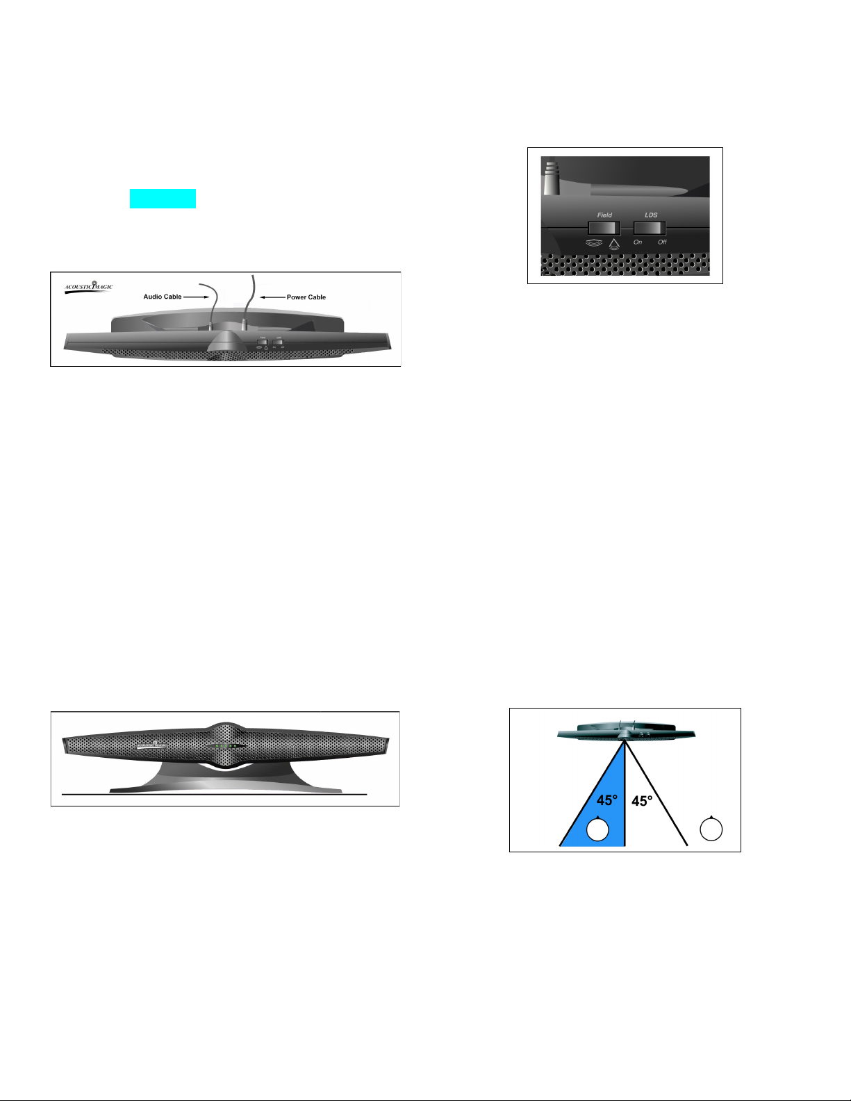
Connect the power and audio cables to their appropriate
jacks on the back of the Voice Tracker
Figure 1). Plug the power adapter into a standard 110volt wall outlet and connect the other end of the audio
cable to the “mic in” input on your computer’s sound
card. The adapter supplies 6V DC power (center pin
positive) to the microphone.
TM
Array (see
Mode Switches
The Voice Tracker
TM
has 4 operational modes, selected
by two switches: the Field switch and the Location
Dependent SquelchTM (LDSTM) switch (see Figure 3).
Figure 3 – Field and LDSTM Switches
Figure 1 – Audio and Power Cable Connections
The Voice Tracker
input device for a variety of speech and multi-media
applications. Many of the software packages which
utilize a speech input have setup tools, which allow you
to specify that you are using the “mic In” connection on
your soundcard and to adjust the sound level (volume)
automatically. Please refer to your specific application
software for details. To adjust the volume or input
selection manually on a Windows PC, see the Adjusting
Your Soundcard section at the end of these
instructions.
TM
Array may be used as the audio
Positioning
Aim the array in the direction of the desired talker(s).
When properly positioned, the talker will be able to see
all 5 green position indicators.
The Field switch determines the scanning range of the
array. In the wide-angle mode, the Voice Tracker
TM
will
scan +/- 90 degrees. This is useful if the user desires to
listen to an entire room. In the narrow-angle mode, the
array will scan +/- 45 degrees. The narrower scanning
range helps to reduce the impact of undesired talkers
and noise sources outside the region of interest. Note
that the Voice Tracker does pick up sound from behind,
giving it a full 360 degree field of view. However, it is
more sensitive in the forward direction.
When the LDSTM switch is set to On, the Voice Tracker
TM
will turn off during periods of silence and when the sound
source is located outside the array’s reception region as
determined by the Field switch. The array turns on
again very quickly when the user resumes talking.
When used together with the narrow field of view, the
LDSTM can be employed to ignore unwanted sounds.
Once the talker pauses and the Voice Tracker
TM
turns
off, the array will only turn on again when sounds come
from within the +/- 45 degree listening area (see Fig 4).
Figure 2 – Voice Tracker
The Voice Tracker
TM
can be tilted up or down to facilitate
TM
Array Front View
mounting on the desktop (tilted up) or on the monitor
(tilted down). For speech recognition applications, the
desktop position will exhibit slightly better performance.
If you mount it on top of the monitor, makes sure it is
secured so it doesn’t fall off. The Voice Tracker can be
mount on the ceiling by removing the weight in its base,
and using the 4 screw hole in the base.
Figure 4 – Listening Area
For speech recognition applications, when the limited
scan range and LDS are on, the generation of spurious
words or commands from sources outside the listening
area will be reduced. However, since the beginnings of
words may be clipped off, recognition accuracy may
suffer. The user should decide whether this feature
improves performance in their particular noise
Page 2

environment. In general, we recommend LDS off and
the narrow field of view for speech recognition
applications.
Using a narrow field of view and LDSTM can also be
useful when teleconferencing. If the incoming talker’s
speech is played through loudspeakers positioned
outside the +/- 45 degree listening area, the array will
turn off when only the far-end talker is active, thereby
minimizing echo in the channel.
Position Lights
The green position lights provide feedback on the
operation of the array. They indicate where the array’s
listening beam is pointing. When the array recognizes a
relevant sound, one of the 5 lights will be illuminated.
The individual lights correspond to the range of potential
sound source locations. For example, if a talker is
directly in front of the array, the middle light will be
illuminated. If the talker is to one side, a light on that side
will turn on. If the talker moves across the field of view of
the array, the lights will track the talker’s motion. When
two users are sharing the array, the light will indicate the
direction of the active talker. In the narrow scanning
range mode, only three lights are active. When there is
no active talker, the lights may flicker as the Voice
Tracker
When the LDS is on, the indicator light will be illuminated
only when there is sound activity within the designated
listening area. With the LDS off, a light will remain on
continuously through both speech and silence periods.
In the event that no lights are on and the LDS mode is
off, it is possible that the array is not plugged in or is
working improperly.
TM
searches for a talker.
Using the Voice Tracker for Speech Recognition
Since the Voice TrackerTM operates differently from other
types of microphones or audio input devices, you should
retrain your speech recognition system after connecting
the array and adjusting the soundcard gain level. This
will allow you to more effectively utilize the improved
sound quality produced by the Voice TrackerTM and will
improve the overall performance of your speech
recognition software. Be sure to select mic in during the
“New User” setup. Personalized vocabulary can usually
be transferred to the retrained “User”.
5. Check the Select box under Mic In and set its
volume to an appropriate level for your soundcard.
Be careful not to set this volume level too high. This
will cause clipping.
6. Exit recording control.
Trouble shooting:
- Audio cuts out: Be sure LDS switch is in off
position
- No audio. Check whether green lights track the
talker. If so, the problem is probably in the
computer. Make sure it is looking for recording
input where the Voice Tracker is connected (mic
in or USB)
FCC & CE Mark Compliance
This equipment has been tested and found to comply the
limits for a Class A digital device, pursuant to part 15 of
the FCC rules as well as the CE Mark rules. These limits
are designed to provide reasonable protection against
interference when the equipment is operated in a
commercial environment. This unit generates, uses and
can radiate radio frequency energy, and if not installed
and used in accordance with the instruction manual, may
cause harmful interference with radio communications.
Changes or modifications not expressly approved by
Acoustic Magic could void the user’s authority to operate
the equipment.
This digital apparatus does not exceed the Class A limits
for radio noise emissions from digital apparatus as set
out in the Radio Interference Regulations of the
Canadian Department of Communications.
If you have further questions, e-mail us at
Or call 978 440 9384.
Adjusting Your Soundcard
On your Windows PC:
1. Go to Start button, Programs, Accessories,
Multimedia (or Entertainment), then volume control.
2. Make sure the Mic In’s mute is checked.
3. Go to Options, then Properties, select the circle next
to Recording.
4. In the ‘Show Volume Controls’ region check the box
next to Mic In and then click OK.
ACOUSTIC MAGIC, INC.
35 Peakham Road
Sudbury, MA 01776
www.ACOUSTICMAGIC.com
 Loading...