

Page 1

7KTA3
User's Manual Version 1.0
The information presented in this publication has been
made carefully for reliability; however, no responsibility
is assumed for inaccuracies. Specifications are subject
to change without notice.
IBM, PC/AT, and PC/XT are trademarks of Interna-
tional Business Machines Corporation.
Athlon is a trademark of AMD Corporation
AWARD is a registered trademark of Phoenix
Sofftware Inc.
MS-DOS and WINDOWS NT are registered trade-
marks of Microsoft Corporation.
Trademarks and/or registered trademarks are the
properties of their respective owners.
i
Page 2

Table of Contents
IntrnctctinnIntrnctctinn
Intrnctctinn
IntrnctctinnIntrnctctinn
1. Mnthdranarc Ddrcriotinn1. Mnthdranarc Ddrcriotinn
1. Mnthdranarc Ddrcriotinn
1. Mnthdranarc Ddrcriotinn1. Mnthdranarc Ddrcriotinn
1.1 Fdattrdr
1.1.1 Harcward 1-1
1.1.1 Snetward 1-4
1.1.3 Attachmdntr 1-4
1.1 Mnthdranarc Inrtallatinn
1.1.1 Mnthdranarc Mao 1-5
1.1.1 Mnthdranarc Layntt 1-6
1.3 Mnthdranarc Cnnndctnrr
1.3.1 Frnnt Pandl Cnnndctnrr(J1( 1-8
1.3.1 Flnooy Dirk Cnnndctnr(FDD( 1-9
1.3.3 Harc Dirk Cnnndctnrr(IDD1.IDD1( 1-9
1.3.4 ATX 10-oin Pnwdr Cnnndctnr(ATX( 1-10
1.3.5 Inerardc Cnnndctnr(IR1( 1-10
1.4 Back Pandl Cnnndctnrr
1.4.1 PS.1 Mntrd.Kdyanarc CNMM. 1-11
1.4.1 USB Cnnndctnrr (USB.USB1( 1-11
1.5 Sdrial anc Paralldl Intdreacd onrtr 1-13
1.6 CPU Inrtallatinn
1.6.1 CPU Inrtallatinn Prnctct(Snckdt 461( 1-15
1.6.1 CPU Clnck Frdqtdncy Sdtting(SW1.JP1( 1-16
1.6.3 CPU FSB Ratin Sdldctinn(SW1( 1-17
1.7 Jtmodr Sdtting
1.7.1 CPU Fan Cnnndctnr(FAM1.1.3( 1-18
1.7.1 Wakd-Nn-Mncdm Hdacdr(WNM1( 1-19
1.7.3 Wakd-Nn-LAM Hdacdr(WNL1( 1-19
1.7.4 AMR CNDDC Sdldctinn(JP3( 1-19
1.7.5 CMNS Ftnctinn Sdldctinn(JP1( 1-10
1.7.6 Kdyanarc Wakd to Sdtting(JPX1( 1-10
1.8 DRAM Inrtallatinn
ii
Page 3

Table of Contents
1.8.1 DIMM 1-11
1.8.1 Hnw tn inrtall a DIMM Mnctld 1-11
1.9 Atcin Staryrtdm
1.9.1 CD-Atcin-IM Cnnndctnrr(CDIM1.CDIM1( 1-11
1. BINS Sdtto1. BINS Sdtto
1. BINS Sdtto
1. BINS Sdtto1. BINS Sdtto
1.1 Main Mdnt 1-4
1.1 Stancarc CMNS Fdattrdr 1-7
1.3 Acuancdc BINS Fdattrdr 1-10
1.4 Acuancdc Chiordt Fdattrdr 1-14
1.5 Intdgratdc Pdriohdralr 1-19
1.6 Pnwdr Managdmdnt Sdtto 1- 1 4
1.7 PnP.PCI Cnneigtratinnr 1-30
1.8 PC Hdalth Stattr 1-34
1.9 Frdqtdncy.Vnltagd Cnntrnl 1-35
1.10 Lnac Fail-Saed Ddeatltr 1-36
1.11 Lnac Notimizdc Ddeatltr 1 -37
1.11 Sdt Stodruirnr.trdr Parrwnrc 1-38
1.13 Saud & Dxit Sdtto 1-40
1.14 Dxit Withntt Sauing 1-41
3. Driudr Inrtallatinn3. Driudr Inrtallatinn
3. Driudr Inrtallatinn
3. Driudr Inrtallatinn3. Driudr Inrtallatinn
3.1 Main Mdnt 3-1
3.1 Inrtalling VIA 4 in 1 Driudr 3-1
3.3 Inrtalling Atcin Driudr 3-3
3.4 Inrtalling Harcward Mnnitnring Utility 3-5
iii
Page 4

Chaosdr 1 Mnshdranarc C drbrh osh nnChaosdr 1 Mnshdranarc C drbrh osh nn
Chaosdr 1 Mnshdranarc C drbrh osh nn
Chaosdr 1 Mnshdranarc C drbrh osh nnChaosdr 1 Mnshdranarc C drbrh osh nn
Introduction
System Overview
This manual was written to help you start using this product
as quickly and smoothly as possbile. Inside, you will find
the answers to solve most problems. In order for this
reference material to be of greatest use, refer to the
“expanded table of contents” to find relevant topics.
This board provides a total PC solution by incorporating the
System, I/O, and PCI IDE. The mainboard support single
AMD Thunderbird and Duron processors base PC ATX
system, ISA Bus, AMR Bus,PCI Local Bus, and AGP Bus to
upgrades your system performance.
It is ideal for multi-tasking and fully supports MS-DOS,
Windows, Windows NT , Windows ME, Windows 2000,
Novell, OS/2, Windows95/98, Windows 98SE , UNIX ,
SCO UNIX etc.
This manual also explains how to install the mainboard for
operation, and how to setup your CMOS configuration with
the BIOS setup program.
1-11-1
1-1
1-11-1
Page 5

Chaosdr 1 Mnshdranarc C drbrh osh nnChaosdr 1 Mnshdranarc C drbrh osh nn
Chaosdr 1 Mnshdranarc C drbrh osh nn
Chaosdr 1 Mnshdranarc C drbrh osh nnChaosdr 1 Mnshdranarc C drbrh osh nn
1.Motherboard Description
1.1 Features
1.1.1 Hardware
CPU
TM
-Single AMD Socket 462 Thunderbird
-100/133MHz System Interface speed.
-AMD DuronTM processors 600~900MHz whith 100MHz FSB.
-AMD Thunderbird
TM
processors 700~1.5GHz with in 100/133MHz
FSB.
Speed
-Supports 33MHz PCI Bus speed.
-Supports 4X AGP Bus.
DRAM Memory
-Supports 8/16/32/64....MB DIMM module socket.
-Supports Synchronous DRAM(3.3V)
-Supports a maximum memory size of 1.536GB with SDRAM.
Shadow RAM
-A memory controller provide shadow RAM and supports
8-bit ROM BIOS.
/ DuronTM.
Green Function
-Support power management operation VIA BIOS.
-Power down timer from 1 to 15 mins.
-Wakes from power saving sleep mode at the press of
any key or any mouse activity.
Bus Slots
-Provide one ISA slot and one AMR slot and AGP slot.
-Five 32-bit PCI bus.
1-11-1
1-1
1-11-1
Page 6

Chaosdr 1 Mnshdranarc C drbrh osh nnChaosdr 1 Mnshdranarc C drbrh osh nn
Chaosdr 1 Mnshdranarc C drbrh osh nn
Chaosdr 1 Mnshdranarc C drbrh osh nnChaosdr 1 Mnshdranarc C drbrh osh nn
Universal Serial Bus
-Supports two back Universal Serial Bus(USB)Ports
and two front Universal serial Bus(USB)Ports.
Hardware Monitor Function
-CPU Fan Speed Monitor.
-CPU Temperature Monitor.
-System Voltage Monitor.
Flash Memory
-Support 2MB flash memory.
-Support ESCD Function.
IDE Bulit-in On Board
-Supports four IDE devices.
-Supports PIO Mode 5, Master Mode, high performance hard disk
drives.
-Support Ultra DMA 33/66/100 Bus Master Mode.
-Supports IDE interface with CD-ROM.
-Supports high capacity hard disk drives.
-Support LBA mode.
PCI-Based AC 97 Digital Audio Processor
-AC 97 2.1 interface.
-16 channels of high-quality sample rate conversion.
-16x8 channel digital mixer.
-Stereo 10 band graphic equalizer.
-Sound Blaster and Sound Blaster Pro emulation.
WOL/WOM (Wake On LAN & Wake On Modem)
Supports system power up from LAN/Modem ring up .
Smart Panel
Supports BIOS Port 80H POST Code output to debug LED.
1-31-3
1-3
1-31-3
Page 7

Chaosdr 1 Mnshdranarc C drbrh osh nnChaosdr 1 Mnshdranarc C drbrh osh nn
Chaosdr 1 Mnshdranarc C drbrh osh nn
Chaosdr 1 Mnshdranarc C drbrh osh nnChaosdr 1 Mnshdranarc C drbrh osh nn
I/O Bulit-in On Board
-Supports one multi-mode Parallel Port.
(1)Standard & Bidirection Parallel Port
(2)Enhanced Parallel Port (EPP)
(3)Extended Capabilities Port
-Supports two serial ports, 16550 UART.
-Supports one Infrared transmission (IR).
-Supports PS/2 mouse and PS/2 Keyboard.
-Supports 360KB, 720KB, 1.2MB, 1.44MB, and 2.88MB floppy disk
drivers.
1.1.2 Software
BIOS
-AWARD legal BIOS.
-Supports APM 1.2.
-Supports USB Function.
-Supports ACPI
Operation System
-Offers the highest performance forMS-DOS,Windows,
Windows NT, Windows 2000, Windows ME, Novell, OS/2,
Windows 95/98, Windows 98 SE, UNIX, SCO UNIX etc.
1.1.3 Attachments
-HDD UDMA66/100 Cable.
-FDD Cable.
-Flash Memory Written for BIOS Update.
-USB2 Cable (Option).
-Fully Setup CD Driver built in Utility(Ghost, Anitivirus,
Adobe Acrobat).
-This Manual.
1-41-4
1-4
1-41-4
Page 8

Chaosdr 1 Mnshdranarc C drbrh osh nnChaosdr 1 Mnshdranarc C drbrh osh nn
Chaosdr 1 Mnshdranarc C drbrh osh nn
Chaosdr 1 Mnshdranarc C drbrh osh nnChaosdr 1 Mnshdranarc C drbrh osh nn
1.2 Motherboard Installation
1.2.1 Motherboard Map
1-51-5
1-5
1-51-5
Page 9

Chaosdr 1 Mnshdranarc C drbrh osh nnChaosdr 1 Mnshdranarc C drbrh osh nn
Chaosdr 1 Mnshdranarc C drbrh osh nn
Chaosdr 1 Mnshdranarc C drbrh osh nnChaosdr 1 Mnshdranarc C drbrh osh nn
1.2.2 Motherboard Layout
JPX1
FAN1
USB
462
COM1
Printer
COM2
Speak out
Line in
MIC in
GAME1
AMR SLOT
JP3
IR1
VIA
AGP SLOT
PCI1
PCI2
PCI3
PCI4
PCI5
ISA SLOT
DIMM1
VIA
JP1
DIMM3
DIMM2
FAN3
1
J1
JP2
FAN2
1-61-6
1-6
1-61-6
Page 10

Chaosdr 1 Mnshdranarc C drbrh osh nnChaosdr 1 Mnshdranarc C drbrh osh nn
Chaosdr 1 Mnshdranarc C drbrh osh nn
Chaosdr 1 Mnshdranarc C drbrh osh nnChaosdr 1 Mnshdranarc C drbrh osh nn
1.3 Motherboard Connectors
8
16
JPX1
Printer
GAME1
14
FAN1
VIA
USB
COM1
1
COM2
Speak out
Line in
MIC in
13
AMR SLOT
JP3
3
AGP SLOT
PCI1
2
6
IR1
4,5
1.Babk Oandk I.O Cnnndbsnrr1.Babk Oandk I.O Cnnndbsnrr
1.Babk Oandk I.O Cnnndbsnrr
1.Babk Oandk I.O Cnnndbsnrr1.Babk Oandk I.O Cnnndbsnrr
3.IR Cnnndbsnr3.IR Cnnndbsnr
3.IR Cnnndbsnr
3.IR Cnnndbsnr3.IR Cnnndbsnr
5.Wakd-On-LAN Cnnndbsnr5.Wakd-On-LAN Cnnndbsnr
5.Wakd-On-LAN Cnnndbsnr
5.Wakd-On-LAN Cnnndbsnr5.Wakd-On-LAN Cnnndbsnr
7.Frnns Oandk Cnnndbsnr(J1(7.Frnns Oandk Cnnndbsnr(J1(
7.Frnns Oandk Cnnndbsnr(J1(
7.Frnns Oandk Cnnndbsnr(J1(7.Frnns Oandk Cnnndbsnr(J1(
9.ICD Cnnndbsnrr9.ICD Cnnndbsnrr
9.ICD Cnnndbsnrr
9.ICD Cnnndbsnrr9.ICD Cnnndbsnrr
11.COU Frdq. Sdsshng(SW1.JO1(11.COU Frdq. Sdsshng(SW1.JO1(
11.COU Frdq. Sdsshng(SW1.JO1(
11.COU Frdq. Sdsshng(SW1.JO1(11.COU Frdq. Sdsshng(SW1.JO1(
13.ATX Onwdr Cnnndbsnr13.ATX Onwdr Cnnndbsnr
13.ATX Onwdr Cnnndbsnr
13.ATX Onwdr Cnnndbsnr13.ATX Onwdr Cnnndbsnr
15.CMOS Ftnbshn n Sdk dbshnn(JO1(15.CMOS Ftnbshn n Sdk dbshnn(JO1(
15.CMOS Ftnbshn n Sdk dbshnn(JO1(
15.CMOS Ftnbshn n Sdk dbshnn(JO1(15.CMOS Ftnbshn n Sdk dbshnn(JO1(
16.Jdyanarc Wakd to Sdsshng(JOX1(16.Jdya narc Wakd to Sdsshng(JOX1(
16.Jdyanarc Wakd to Sdsshng(JOX1(
16.Jdyanarc Wakd to Sdsshng(JOX1(16.Jdya narc Wakd to Sdsshng(JOX1(
PCI2
PCI3
PCI4
PCI5
12
462
11
11
9
8
10
7
8
ISA SLOT
VIA
JP1
DIMM3
DIMM2
DIMM1
FAN3
1
J1
JP2
FAN2
15
1.CC Atchn-In Cnnndbsnr1.CC Atchn-In Cnnndbsnr
1.CC Atchn-In Cnnndbsnr
1.CC Atchn-In Cnnndbsnr1.CC Atchn-In Cnnndbsnr
4.Wakd-On MOCDM Cnnndbsnr4.Wakd-On MOCDM Cnnndbsnr
4.Wakd-On MOCDM Cnnndbsnr
4.Wakd-On MOCDM Cnnndbsnr4.Wakd-On MOCDM Cnnndbsnr
6.Frnns USB1 Cnnndbsnr6.Frnns USB1 Cnnndbsnr
6.Frnns USB1 Cnnndbsnr
6.Frnns USB1 Cnnndbsnr6.Frnns USB1 Cnnndbsnr
8.Fan Cnnndbsnrr(Fan1 .1.3(8.Fan Cnnndbsnrr(Fan1 .1.3(
8.Fan Cnnndbsnrr(Fan1 .1.3(
8.Fan Cnnndbsnrr(Fan1 .1.3(8.Fan Cnnndbsnrr(Fan1 .1.3(
10.Fknooy Cnnndbsnr10.Fknooy Cnnndbsnr
10.Fknooy Cnnndbsnr
10.Fknooy Cnnndbsnr10.Fknooy Cnnndbsnr
11.COU Rashn Sdkdbshn n(SW1(11.COU Rashn Sdk dbshn n(SW1(
11.COU Rashn Sdkdbshn n(SW1(
11.COU Rashn Sdkdbshn n(SW1(11.COU Rashn Sdk dbshn n(SW1(
14.AMR COCDC Sdkdbshnn(JO3(14.AMR COCDC Sdkdbshnn(JO3(
14.AMR COCDC Sdkdbshnn(JO3(
14.AMR COCDC Sdkdbshnn(JO3(14.AMR COCDC Sdkdbshnn(JO3(
1-71-7
1-7
1-71-7
Page 11

Chaosdr 1 Mnshdranarc C drbrh osh nnChaosdr 1 Mnshdranarc C drbrh osh nn
Chaosdr 1 Mnshdranarc C drbrh osh nn
Chaosdr 1 Mnshdranarc C drbrh osh nnChaosdr 1 Mnshdranarc C drbrh osh nn
1.3.1 Front Panel Connector (J1)
J1 PANEL Connector
PW_BN
PW_LED
HDLED
+
KBLOCK
+
+
1
RSTSW
+
EXTSMI
+
SPEAKER
2
+
+
SMI_LED
Speaker Connector (SPEAKER)
An offboard speaker can be installed onto the motherboard as a
manufacturing option. An offboard speaker can be connected to
the motherboard at the front pannel connector. The speaker
(onboard or offboard) provides error beep code information during the Power Self-Test when the computer cannot use the video
interface. The speaker is not connected to the audio subsystem
and does not receive output from the audio subsystem.
Hard Drive LED Connector (HDLED)
This connector supplies power to the cabinet IDE activity LED.
Read and write activity by devices connected to the Primary or
Secondary IDE connectors will cause the LED to light up.
SMI Suspend Switch Lead (EXTSMI)
This allows the user to manually place the system into a suspend
mode of Green mode. System activity will be instantly decreased
to save electricity and expand the life of certain components
when the system is not in use. This 2-pin connector (see the
figure) connects to the case-mounted suspend switch. If you do
not have a switch for the connector, you may use the "Turbo
Switch” instead since it does not have a function. SMI is
activated when it detects a short. It may require one or two
pushes depending on the position of the switch. Wake-up can be
controlled by settings in the BIOS but the keyboard will always
allow wake-up (the SMI Suspend Switch Lead cannot wake-up
the system). If you want to use this connector, the "Suspend
Switch" in the Power Management Setup of the BIOS SOFTWARE section should be on the default setting of Enable.
1-81-8
1-8
1-81-8
Page 12

Chaosdr 1 Mnshdranarc C drbrh osh nnChaosdr 1 Mnshdranarc C drbrh osh nn
Chaosdr 1 Mnshdranarc C drbrh osh nn
Chaosdr 1 Mnshdranarc C drbrh osh nnChaosdr 1 Mnshdranarc C drbrh osh nn
ATX Power Switch (PW_BN)
The system power is controlled by a momentary switch
connected to this lead. Pushing the button once will switch
the system ON. The system power LED lights when the
system's power is on .
Power LED Lead (PW_LED)
The system power LED lights when the system power is on.
Keyboard Lock (KBLOCK)
The header is for setting keyboard locked.
Reset Switch Lead (RSTSW)
The connector can be connected to a momentary SPST type
switch that is normally open. When the switch is closed, the
motherboard resets and runs the POST.
SMI_LED Lead (SMI_LED)
The system SMI_LED lights when the system suspend is on.
1.3.2 Floppy Disk Connector (FDD)
This connector supports the provided floppy drive ribbon
cable. After connecting the single end to the board, connect
the two plugs on the other end to the floppy drives.
1.3.3 Hard Disk Connectors (IDE1/IDE2)
These connectors support the provided IDE hard disk ribbon
cable. After connecting the single end to the board, connect
the two plugs at the other end to your hard disk.
If you install two hard disks, you must configure the second
drive to Slave mode by setting its jumper settings. BIOS now
supports SCSI device or IDE CD-ROM boot up (see "HDD
Sequence SCSI/IDE First" & "Boot Sequence" in the BIOS
Features Setup of the BIOS SOFTWARE) (Pin 20 is removed
to prevent inserting in the wrong orientation when using
ribbon cables with pin 20 plugged) .
1-91-9
1-9
1-91-9
Page 13

Chaosdr 1 Mnshdranarc C drbrh osh nnChaosdr 1 Mnshdranarc C drbrh osh nn
Chaosdr 1 Mnshdranarc C drbrh osh nn
Chaosdr 1 Mnshdranarc C drbrh osh nnChaosdr 1 Mnshdranarc C drbrh osh nn
1.3.4 ATX 20-pin Power Connector (ATX)
This connector supports the power button on-board. Using
the ATX power supply, functions such as Modem Ring Wake-
Up and Soft Power Off are supported on this motherboard .
This power connector supports instant power-on
functionality, which means that the system will boot up
instantly when the power connector is inserted on the board.
Pin Signal Pin Signal
1 3.3V 11 3.3V
2 3.3V 12 -12V
3 GND 13 GND
4 5V 14 PS-ON
5 GND 15 GND
6 5V 16 GND
7 GND 17 GND
8 PW-OK 18 -5V
9 5V_SB 19 5V
10 12V 20 5V
1.3.5 Infrared Connector (IR1)
After the IrDA interface is configured, files can be
transferred from or to portable devices such as laptops,
PDAs, and printers using application software.
1-101-10
1-10
1-101-10
Page 14

Chaosdr 1 Mnshdranarc C drbrh osh nnChaosdr 1 Mnshdranarc C drbrh osh nn
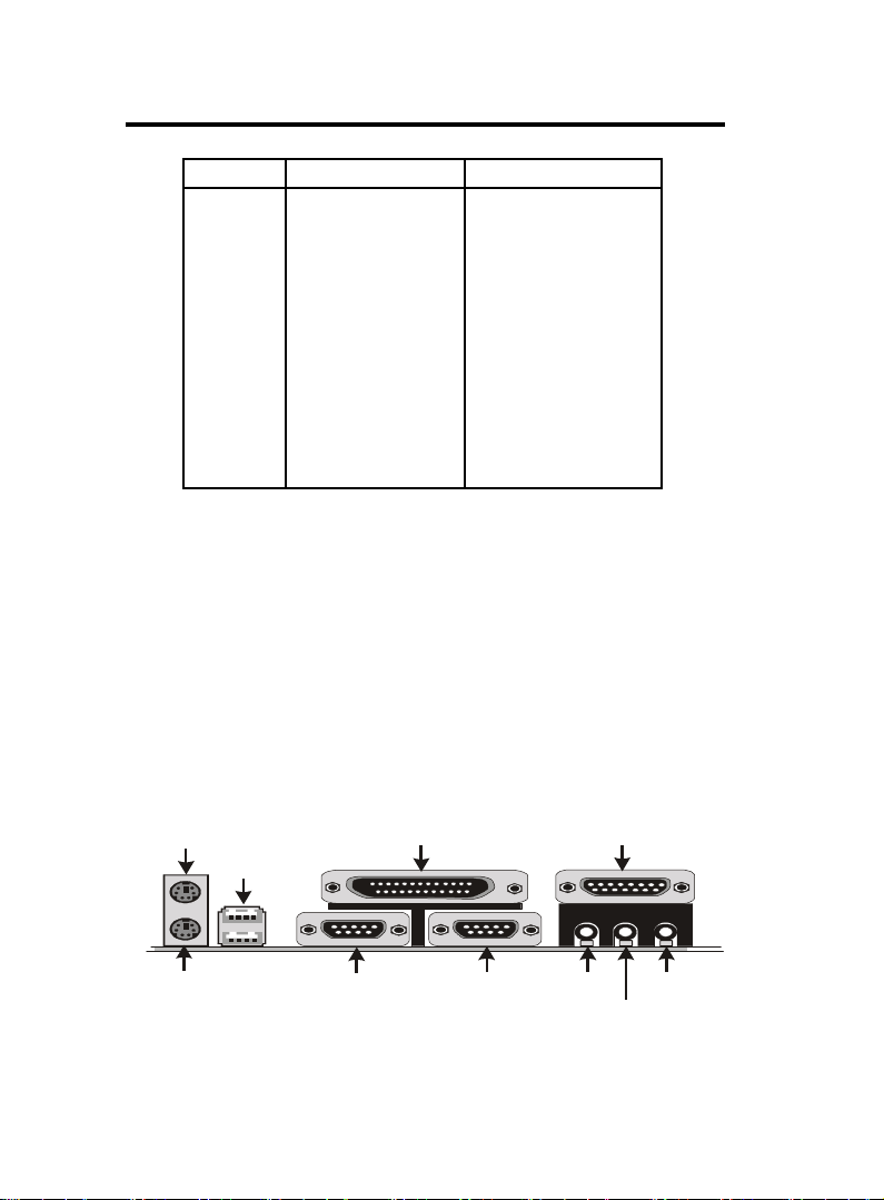
Serial Port(9-pin Male)
LINE IN
Parallel (Printer) Port
MIDI/(GAME) Port
Chaosdr 1 Mnshdranarc C drbrh osh nn
Chaosdr 1 Mnshdranarc C drbrh osh nnChaosdr 1 Mnshdranarc C drbrh osh nn
1.4 Back Panel Connectors
PS/2 Mouse
(25-pin Fem ale)
USB
(15-pin Fem ale)
PS/2 Keyboard
(6-pin Fem ale)
COM1
COM2
SPEAKER
1.4.1 PS/2 Mouse /Keyboard CONN.
The motherboard provides a standard PS/2 mouse / Keyboard
mini DIN connector for attaching a PS/2 mouse. You can
plug a PS/2 mouse / Keyboard directly into this connector.
1.4.2 USB Connectors: USB & USB1
The motherboard provides a OHCI(Open Host Controller
Interface)Universal Serial Bus Roots for attaching USB
devices such as a keyboard, mouse and other USB devices.
You can plug the USB devices directly into this connector.
Pin Signal
1 +5V_SB
2 USBP0-(USBP1-)
USB
3 USBP0+(USBP1+)
4 GND
MIC
1-111-11
1-11
1-111-11
Page 15

Chaosdr 1 Mnshdranarc C drbrh osh nnChaosdr 1 Mnshdranarc C drbrh osh nn
Chaosdr 1 Mnshdranarc C drbrh osh nn
Chaosdr 1 Mnshdranarc C drbrh osh nnChaosdr 1 Mnshdranarc C drbrh osh nn
Front Two USB Connectors: USB1
JPX1
Printer
GAME1
FAN1
AMR SLOT
JP3
VIA
AGP SLOT
PCI1
462
JP1
DIMM3
DIMM2
DIMM1
FAN3
Speak out
Line in
MIC in
USB
COM1
COM2
USB1
VCC
P2-
P2+
GND
GND
1-111-11
1-11
1-111-11
PCI2
PCI3
PCI4
PCI5
ISA SLOT
VIA
1
J1
JP2
FAN2
IR1
1
3
5
7
9
2
GND
4
GND
6
P3+
8
P3-
10
VCC
Page 16

Chaosdr 1 Mnshdranarc C drbrh osh nnChaosdr 1 Mnshdranarc C drbrh osh nn
Chaosdr 1 Mnshdranarc C drbrh osh nn
Chaosdr 1 Mnshdranarc C drbrh osh nnChaosdr 1 Mnshdranarc C drbrh osh nn
1.5 Serial and Parallel Interface Ports
This system comes equipped with two serial ports and one
parpllel port. Both types of interface ports will be explained
in this chapter.
The Serial Interfaces: COM1/COM2
The serial interface port is sometimes refered to as an RS-
232 port or an asynchronous communication port. Mice,
printers, modems and other peripheral devices can be
connected to a serial port. The serial port can also be used
to connect your computer system. If you wish to transfer
the contents of your hard disk to another system it can be
accomplished by using each machine’s serial port.
COM1/COM2
The serial port on this system has one 9-pin connector.
Some older computer systems and peripherals used to be
equipped with only a 25-pin connector. Should you need to
connect your 9-pin serial port to an older 25-pin serial port,
you can purchase a 9-to-25 pin adapter.
1-131-13
1-13
1-131-13
Page 17
Chaosdr 1 Mnshdranarc C drbrh osh nnChaosdr 1 Mnshdranarc C drbrh osh nn
Serial Port(9-pin Male)
LINE IN
Parallel (Printer) Port
MIDI/(GAME) Port
Chaosdr 1 Mnshdranarc C drbrh osh nn
Chaosdr 1 Mnshdranarc C drbrh osh nnChaosdr 1 Mnshdranarc C drbrh osh nn
Signal DB9 Pin DB25 Pin
DCD 1 8
RX 2 3
TX 3 2
DTR 4 2 0
GND 5 7
DSR 6 6
RTS 7 4
CTS 8 5
RI 9 2 2
Parallel Interface Port
Unlike serial ports, parallel interface ports have been
standardized and should not present any difficulty interfacing
peripherals to your system. Sometimes called a Centronics port,
the parallel port is almost exclusively used with printers. The
parallel port on your system has a 25-pin, DB 25 connector(see
the picture below).
PS/2 Mouse
PS/2 Keyboard
(6-pin Fem ale)
USB1
COM1
(25-pin Fem ale)
1-141-14
1-14
1-141-14
COM2
SPEAKER
(15-pin Fem ale)
MIC
Page 18

Chaosdr 1 Mnshdranarc C drbrh osh nnChaosdr 1 Mnshdranarc C drbrh osh nn
Chaosdr 1 Mnshdranarc C drbrh osh nn
Chaosdr 1 Mnshdranarc C drbrh osh nnChaosdr 1 Mnshdranarc C drbrh osh nn
1.6 CPU Installation
1.6.1 CPU Installation Procedure: Socket 462
1. Pull the lever sideways away from the socket then raise
the lever to a 90-degree angle.
2. Locate Pin 1 in the socket and look for the white dot or
cut edge in the CPU. Match Pin 1 with the white dot/cut
edge then insert the CPU.
3. Press the lever down to complete the installation.
4. Make sure the spec of the heatsink is good enough.
JPX1
Printer
GAME1
FAN1
AMR SLOT
JP3
VIA
AGP SLOT
PCI1
462
Socket 462
JP1
DIMM3
DIMM2
DIMM1
FAN3
Speak out
Line in
MIC in
USB
COM1
COM2
IR1
PCI2
PCI3
PCI4
PCI5
ISA SLOT
1-151-15
1-15
1-151-15
VIA
1
J1
JP2
FAN2
Notch
Page 19

Chaosdr 1 Mnshdranarc C drbrh osh nnChaosdr 1 Mnshdranarc C drbrh osh nn
Chaosdr 1 Mnshdranarc C drbrh osh nn
Chaosdr 1 Mnshdranarc C drbrh osh nnChaosdr 1 Mnshdranarc C drbrh osh nn
1.6.2 CPU Clock Frequency Setting: SW1/JP1
Overclocking is operating a CPU/Processor beyond its
specified frequency. JP1 jumper is used for the CPU Front
Side Bus Frequencies from 100MHz to 133MHz.
JPX1
Printer
GAME1
FAN1
AMR SLOT
JP3
VIA
AGP SLOT
PCI1
462
1
1
JP1
DIMM3
DIMM2
DIMM1
3
4
FAN3
COM1
COM2
Speak out
Line in
MIC in
USB
IR1
SW1 1 2 3 4 CPU (MHz) PCI (MHz)
PCI2
PCI3
PCI4
PCI5
ISA SLOT
VIA
1
J1
JP2
FAN2
0 1 0 0 100 33.33
0 1 1 0 133 33.33
Pin JP1 Assignment
On CPU FSB=100MHz
(Default)
Off CPU FSB=133MHz
1-161-16
1-16
1-161-16
0:0:
0:
0:0:
O ffO ff
O ff
O ffO ff
1:1:
1:
1:1:
OnOn
On
OnOn
Page 20

Chaosdr 1 Mnshdranarc C drbrh osh nnChaosdr 1 Mnshdranarc C drbrh osh nn
Chaosdr 1 Mnshdranarc C drbrh osh nn
Chaosdr 1 Mnshdranarc C drbrh osh nnChaosdr 1 Mnshdranarc C drbrh osh nn
1.6.3 CPU Ratio Selection: SW2
SW2 jumper is used for the CPU Ratio selection.
JPX1
Printer
GAME1
FAN1
AMR SLOT
JP3
IR1
VIA
AGP SLOT
PCI1
PCI2
PCI3
PCI4
PCI5
462
ISA SLOT
VIA
4
JP1
DIMM3
DIMM2
DIMM1
FAN3
1
J1
JP2
FAN2
3
1
1
0
USB
Ratio SW2 0 1 2 3 4
COM1
Auto ** 1 0 0 0 0
Manual
COM2
5.0 0 1 1 0 1
Speak out
5.5 0 0 1 0 1
Line in
MIC in
6.0 0 1 0 0 1
6.5 0 0 0 0 1
7.0 0 1 1 1 0
7.5 0 0 1 1 0
8.0 0 1 0 1 0
8.5 0 0 0 1 0
9.0 0 1 1 0 0
9.5 0 0 1 0 0
10.0 0 1 0 0 0
10.5 0 0 0 0 0
11.0 01111
11.5 00111
12.0 0 1 0 1 1
12.5 0 0 0 1 1
“**” is default.
1-171-17
1-17
1-171-17
0:0:
0:
0:0:
O ffO ff
O ff
O ffO ff
1:1:
1:
1:1:
OnOn
On
OnOn
Page 21

Chaosdr 1 Mnshdranarc C drbrh osh nnChaosdr 1 Mnshdranarc C drbrh osh nn
Chaosdr 1 Mnshdranarc C drbrh osh nn
Chaosdr 1 Mnshdranarc C drbrh osh nnChaosdr 1 Mnshdranarc C drbrh osh nn
1.7 Jumper Setting
A jumper has two or more pins that can be covered by a
plastic jumper cap, allowing you to select different system
options.
JPX1
FAN1
Connector
JPX1
USB
COM1
COM2
FAN1
462
Printer
VIA
Speak out
JP3
Line in
MIC in
GAME1
AMR SLOT
JP3
AGP SLOT
PCI1
IR1
PCI2
PCI3
WOM1
WOL1
PCI4
PCI5
ISA SLOT
1.7.1 CPU/System Fan Connector: Fan1/2
Pin Assignment
1 Signal
1
2
2 +12VDC
3
3 Ground
VIA
SW2
SW1
JP1
JP1
DIMM3
DIMM2
DIMM1
FAN 3
Connector
FAN3
JP2
1
J1
JP2
FAN 2
Connector
FAN2
1-181-18
1-18
1-181-18
Page 22

Chaosdr 1 Mnshdranarc C drbrh osh nnChaosdr 1 Mnshdranarc C drbrh osh nn
Chaosdr 1 Mnshdranarc C drbrh osh nn
Chaosdr 1 Mnshdranarc C drbrh osh nnChaosdr 1 Mnshdranarc C drbrh osh nn
1.7.1 CPU/System Fan Connectors: Fan3
Pin Assignment
1NA
1
2
2 +12VDC
3
3 Ground
1.7.2 Wake-On Modem Header: WOM1
Pin Assignment
1 5VSB
1
2 Ground
3
3 Signal
1.7.3 Wake-On LAN Header: WOL1
Pin Assignment
1 5VSB
1
2 Ground
3
3 Signal
1.7.4 AMR CODEC Selection: JP3
Pin Assignment
1-2 Onboard CODEC
(Default)
2-3 AMR Primary CODEC
1-191-19
1-19
1-191-19
Page 23

Chaosdr 1 Mnshdranarc C drbrh osh nnChaosdr 1 Mnshdranarc C drbrh osh nn
Chaosdr 1 Mnshdranarc C drbrh osh nn
Chaosdr 1 Mnshdranarc C drbrh osh nnChaosdr 1 Mnshdranarc C drbrh osh nn
1.7.5 CMOS Function Select: JP2
Pin Assignment
1-2 Normal (Default)
2-3 Clear CMOS
NOTE:
(Please follow the procedure below to clear CMOS data.)
(1)Remove the AC power line.
(2)JP2(2-3)Closed.
(3)Wait five seconds.
(4)JP2(1-2) Closed.
(5)AC Power on.
(6)Reset your desired password or clear CMOS data.
1.7.6 Keyboard Wake up Setting: JPX1
The JPX1 Jumper is for setting keyboard power.This
function is provided by keyboard wake-up function.
Pin Assignment
1-2 Keyboard on enabled
2-3 Keyboard on disabled
(Default)
1-101-10
1-10
1-101-10
Page 24

Chaosdr 1 Mnshdranarc C drbrh osh nnChaosdr 1 Mnshdranarc C drbrh osh nn
Chaosdr 1 Mnshdranarc C drbrh osh nn
Chaosdr 1 Mnshdranarc C drbrh osh nnChaosdr 1 Mnshdranarc C drbrh osh nn
1.8 DRAM Installation
1.8.1 DIMM
DRAM Access Time: 3.3V Unbuffered SDRAM PC100
and PC133 Type required.
DRAM Type: 8MB, 16MB, 32MB, 64MB, 128MB, 256MB,
512MB DIMM Module.(168 pin)
Bank Memory module
DIMM 1 16MB,32MB, 64MB, 128MB, 256MB, 512MB
( Bank 0-1 ) 168 pin, 3.3v SDRAM
DIMM 2 16MB,32MB, 64MB, 128MB, 256MB, 512MB
( Bank 2-3 ) 168 pin, 3.3vSDRAM
DIMM 3 16MB,32MB, 64MB, 128MB, 256MB, 512MB
( Bank 4-5 ) 168 pin, 3.3v SDRAM
Total System Memory(Max 1.536GB)
1.8.2 How to install a DIMM Module
1. The DIMM socket has a “Plastic Safety Tab” and the DIMM
memory module has an asymmetrical notch”, so the DIMM
memory module can only fit into the slot in one direction.
2. Push the tabs out. Insert the DIMM memory modules
into the socket at a 90-degree angle then push down
vertically so that it will fit into place.
3. The Mounting Holes and plastic tabs should fit over the
edge and hold the DIMM memory modules in place.
168Ohn C IMM Snbkds168Ohn C IMM Snbkds
168Ohn C IMM Snbkds168Ohn C IMM Snbkds
168Ohn C IMM Snbkds
88 pins 60 pins 20 pins
1-111-11
1-11
1-111-11
Page 25

Chaosdr 1 Mnshdranarc C drbrh osh nnChaosdr 1 Mnshdranarc C drbrh osh nn
Chaosdr 1 Mnshdranarc C drbrh osh nn
Chaosdr 1 Mnshdranarc C drbrh osh nnChaosdr 1 Mnshdranarc C drbrh osh nn
1.9 Audio Subsystem
JPX1
Printer
GAME1
FAN1
AMR SLOT
JP3
IR1
VIA
AGP SLOT
PCI1
PCI2
PCI3
PCI4
PCI5
462
ISA SLOT
VIA
JP1
DIMM3
DIMM2
DIMM1
FAN3
1
J1
JP2
FAN2
CDIN1
CDIN2
Speak out
Line in
MIC in
USB
COM1
COM2
1.9.1 CD Audio-in Connectors: CDIN1/CDIN2
Pin CDIN1 Assignment
1 CD-L
2 GND
3 GND
4 CD-R
Pin CDIN2 Assignment
1 GND
2 CD-L
3 GND
4 CD-R
1-111-11
1-11
1-111-11
Page 26

Bhapter 1 BIOS Sett pBhapter 1 BIOS Sett p
Bhapter 1 BIOS Sett p
Bhapter 1 BIOS Sett pBhapter 1 BIOS Sett p
2. BIOS Setup
Introduction
This manual discussed the Award Setup program built into
the ROM BIOS. The Setup program allows the user to modify
the basic system configuration. This special information is
then stored in battery-backed RAM so that it retains the setup
information when the power is turned off.
The Award BIOS installed in your computer system’s ROM
(Read Only Memory)is a custom version of an industry
standard BIOS. This means that it supports AMD-Thunderbird
/ Duron processors input/output system. The BIOS provides
critical low-level support for standard devices such as disk
drives and serial and parallel ports.
The rest of this manual is intended to guide you through the
process of configuring your system using Setup.
Plug and Play Support
This AWARD BIOS supports the Plug and Play Version
1.0A specification. ESCD(Extended System Configuration
Data)write is supported.
EPA Green PC Support
This AWARD BIOS supports Version 1.03 of the EPA Green
PC specification.
1-11-1
1-1
1-11-1
Page 27

Bhapter 1 BIOS Sett pBhapter 1 BIOS Sett p
Bhapter 1 BIOS Sett p
Bhapter 1 BIOS Sett pBhapter 1 BIOS Sett p
APM Support
This AWARD BIOS supports Version 1.1&1.2 of the
Advanced Power Management(APM) specification.Power
management features are implemented via the System
Management Interrupt(SMI). Sleep and Suspend power
management modes are supported. Power to the hard disk
drives and video monitors can be managed by this AWARD
BIOS.
PCI Bus Support
This AWARD BIOS also supports Version 2.1 of the Intel
PCI (Peripheral Component Interconnect)local bus
specification.
Support CPU
This AWARD BIOS supports the AMD-Thunderbird / Duron
processor CPU.
Using Setup
In general, you use the arrow keys to highlight items, press
<Enter>to select, use the <PgUp>and <PgDn>keys to
change entries, press<F1>for help and press <Esc>to quit.
The following table provides more detail about how to
navigate in the Setup program by using the keyboard.
Note:
(BIOS version 1.0 is for reference only. If there is a
change in BIOS version, please use the actual version
on the BIOS.)
1-11-1
1-1
1-11-1
Page 28

Bhapter 1 BIOS Sett pBhapter 1 BIOS Sett p
Bhapter 1 BIOS Sett p
Bhapter 1 BIOS Sett pBhapter 1 BIOS Sett p
Keystroke Function
Up arrow Move to previous item
Down arrow Move to next item
Left arrow Move to the item on the left(menu bar)
Right arrow Move to the item on the right(menu bar)
Esc Main Menu: Quit without saving changes
Submenus: Exit Current page to the next higher
level menu
Move Enter Move to item you desired
PgUp key Increase the numeric value or make changes
PgDn key Decrease the numeric value or make changes
+Key Increase the numeric value or make changes
-Key Decrease the numeric value or make changes
Esc Key Main menu-Quit and not save changes into
CMOS
Status Page Setup Menu and option Page Setup
Menu-Exit Current page and return to Main
Menu
F1 Key General help on Setup navigation keys.
F5 Key Load previous values from CMOS
F6 Key Load the fail-safe defaults from BIOS default
table
F7 Key Load the optimized defaults
F10 Key Save all the CMOS changes and exit
1-21-2
1-2
1-21-2
Page 29

Bhapter 1 BIOS Sett pBhapter 1 BIOS Sett p
Bhapter 1 BIOS Sett p
Bhapter 1 BIOS Sett pBhapter 1 BIOS Sett p
2.1 Main Menu
Once you enter AWARD BIOS CMOS Setup Utility, the Main
Menu will appear on the screen. The Main Menu allows you
to select from several setup function. Use the arrow keys to
select among the items and press<Enter> to accept and
enter the sub-menu.
“WARNING”
The information about BIOS defaults on manual (Figure
1,2,3,4,5,6,7,8,9,10,11,12,13,14)is just for reference, please
refer to the BIOS installed on the board for updated
information.
◎◎
◎ Figure 1. Main Menu
◎◎
CMOS Setup Utility-Copyright(C) 1984-2001 Award Software
Standard CMOS Features Frequency/Voltage Control
Advanced BIOS Features Load Fail-Safe Defaults
Advanced Chipset Features Load Optimized Defaults
Integrated Peripherals Set Supervisor Password
Power Management Setup Set User Password
PNP/PCI Configurations Save & Exit Setup
PC Health Status Exit Without Saving
Esc : Quit F9 : Menu in BIOS ←→↑↓: Select Item
F10 : Save & Exit Setup
Time , Date , Hard Disk Type ...
Standard CMOS Features
This setup page includes all the items in standard compatible
BIOS.
1-41-4
1-4
1-41-4
Page 30

Bhapter 1 BIOS Sett pBhapter 1 BIOS Sett p
Bhapter 1 BIOS Sett p
Bhapter 1 BIOS Sett pBhapter 1 BIOS Sett p
Advanced BIOS Features
This setup page includes all the items of the BIOS special
enchanced features.
Advanced Chipset Features
This setup page includes all the items of the Chipset special
enchanced features.
Integrated Peripherals
This selection page includes all the items of the IDE hard
drive and Programmed Input/Output features.
Power Management Setup
This setup page includes all the items of the power manage
ment features.
PnP/PCI Configurations
This setup page includes the user defined or default IRQ
Setting.
PC Health Status
This page shows the hardware Monitor information of the
system.
Frequency / Voltage Control
This setup page controls the CPU's clock and frequency ratio.
Load Fail-Safe Defaults
Use this menu to load the BIOS default values for the
minimal/stable performance for your system to operate.
1-51-5
1-5
1-51-5
Page 31

Bhapter 1 BIOS Sett pBhapter 1 BIOS Sett p
Bhapter 1 BIOS Sett p
Bhapter 1 BIOS Sett pBhapter 1 BIOS Sett p
Load Optimized Defaults
These settings are more likely to configure a workable
computer when something is wrong. If you cannot boot the
computer successfully, select the BIOS Setup options and
try to diagnose the problem after the computer boots. These
settings do not provide optional performance.
Set Supervisor Password
Change, set, or, disable password.It allows you to limit
accessto the system and Setup, or just to Setup.
Set User Password
You can specify both a User and a Supervisor password. When
you select either password option, you are prompted for a
1-6 character password. Enter the password and then retype
the password when prompted.
Save & Exit Setup
Save CMOS value changes to CMOS and exit setup.
Exit Without Saving
Abandon all CMOS value changes and exit setup.
1-61-6
1-6
1-61-6
Page 32

Bhapter 1 BIOS Sett pBhapter 1 BIOS Sett p
Bhapter 1 BIOS Sett p
Bhapter 1 BIOS Sett pBhapter 1 BIOS Sett p
2.2 Standard CMOS Features
This item in the Standard CMOS Setup Menu is divided into
10 categories. Each category includes no, one or more than
one setup items. Use the arrow keys to highlight the item
and then use the <PgUp> or <PgDn> keys to select the value
you want in each item.
◎◎
◎ Figure 2. Standard CMOS Features
◎◎
CMOS Setup Utility-Copyright(C) 1984-2001 Award Software
Standard CMOS Features
Date(mm:dd:yy) Tue,Jun 6 2000 Item Help
Time (hh:mm:ss) 11:26:10
IDE Primary Master None
IDE Primary Slave Change the day,
IDE Secondary Master month,year
IDE Secondary Master None and century.
Drive A 1.44M,3.5 in
Drive B None
Floppy 3 Mode Support Disabled
Video EGA/VGA
Halt On All,But Keyboard
Base Memory 640K
Extended Memory 65472K
Total 1024K
←→↑↓: Move Enter:Select +/-/PU/PD:Value F10:Save ESC:Exit
F1:General Help F5:Previous Values F6:Fail-Safe Defaults
F7:Optimized Defaults
Menu Level
1-71-7
1-7
1-71-7
Page 33

Bhapter 1 BIOS Sett pBhapter 1 BIOS Sett p
Bhapter 1 BIOS Sett p
Bhapter 1 BIOS Sett pBhapter 1 BIOS Sett p
Main Menu Selections
This table shows the selections that you can make on the
Main Menu.
Item Options Description
Date Month DD YYYY Set the system,date. Note that the
‘Day’ automatically changes
when you set the data.
IDE Primary Options are in its sub Press<Enter> to enter the sub menu
Master menu. of detailed.
IDE Primary Options are in its sub Press<Enter> to enter the sub menu
Slave menu. of detailed.
IDE Secondary Options are in its sub Press<Enter> to enter the sub menu
Master menu. of detailed.
IDE Secondary Options are in its sub Press<Enter> to enter the sub menu
Slave menu. of detailed.
Drive A None Select the type of floppy disk drive
Drive B 360K, 5.25in installed in your system.
1.2M, 5.25in
720K, 3.5in
1.44M, 3.5in
2.88M, 3.5in
Video EGA/VGA Select the default video device.
CGA 40
CGA 80
MONO
1-81-8
1-8
1-81-8
Page 34

Bhapter 1 BIOS Sett pBhapter 1 BIOS Sett p
Bhapter 1 BIOS Sett p
Bhapter 1 BIOS Sett pBhapter 1 BIOS Sett p
Item Options Description
Halt On All Errors Select the situation in which you
No Errors want the BIOS to stop the POST
All, but Keyboard process and notify.
All, but Diskette
All, but Disk/Key
Base Memory N/A Displays the amount of conventional
memory detected during boot up.
Extended N/A Displays the amount of conventional
Memory memory detected during boot up.
Total N/A Displays the total memory
Memory available in the system.
CMOS Setup Utility-Copyright (C) 1984-2001Award Software IDE
Primary Master
IDE HDD Auto-Detection Press Enter Item Help
IDE Primary Master Auto
Access Mode Auto Menu Level
Capacity 13022MB
Cylinder 25232
Head 16
Precomp 0
Landing Zone 25231
Sector 61
←→↑↓: Move Enter:Select +/-/PU/PD:Value F10:Save ESC:Exit
F1:General Help F5:Previous Values F6:Fail-Safe Defaults
F7:Optimized Defaults
1-91-9
1-9
1-91-9
Page 35

Bhapter 1 BIOS Sett pBhapter 1 BIOS Sett p
Bhapter 1 BIOS Sett p
Bhapter 1 BIOS Sett pBhapter 1 BIOS Sett p
2.3 Advanced BIOS Features
◎◎
◎ Figure 3. Advanced BIOS Features
◎◎
CMOS Setup Utility-Copyright(C) 1984-2001 Award Software
Advanced BIOS Features
Virus Warning Disabled Item Help
CPU Internal Cache Enabled
External Cache Enabled Menu Level
CPU L2 Cache ECC Checking Enabled
Quick Power On Self Test Enabled Allows you to
First Boot Device Floopy choose the
Second Boot Device HDD-0 VIRUS warning
Third Boot Device LS120 feature for IDE
Boot Other Device Enabled Hard Disk boot
Swap Floppy Drive Disabled sector protection.
Boot Up Floppy Seek Disabled If this function
Boot Up NumLock Status On is enabled and
Gate A20 Option Fast someone attempts
Typematic Rate Setting Disabled to write data into
Typematic Rate (Chars/Sec) 6 this area,BIOS
Typematic Delay (Msec) 2 50 will show a
Security Option Setup warning message
OS Select For DRAM Non-OS2 on screen and
Report No FDD For WIN 95 No alarm beep
Video BIOS Shadow Enabled
C8000-CBFFF Shadow Disabled
CC8000-CFFFF Shadow Disabled
D0000-D3FFF Shadow Disabled
D4000-D7FFF Shadow Disabled
D88000-DBFFF Shadow Disabled
DC000-DFFFF Shadow Disabled
Small Logo(EPA) Show Disabled
←→↑↓: Move Enter:Select +/-/PU/PD:Value F10:Save ESC:Exit
F1:General Help F5:Previous Values F6:Fail-Safe Defaults
F7:Optimized Defaults
Virus Warning
This option allows you to choose the VIRUS Warning
feature for IDE Hard Disk boot sector protection. If this
function is enabled and someone attempts to write data into
this area, BIOS will show a warning message on screen and
alarm beep.
The Choices: Disabled(default), Enabled.
1-101-10
1-10
1-101-10
Page 36

Bhapter 1 BIOS Sett pBhapter 1 BIOS Sett p
Bhapter 1 BIOS Sett p
Bhapter 1 BIOS Sett pBhapter 1 BIOS Sett p
CPU Internal Cache
These two categories speed up memory access. However,
it depends on CPU/chipset design.
Enabled (default) Enabled cache.
Disabled Disabled cache.
External Cache
This fields allow you to Enable or Disable the CPU’S
“Level 2” secondary cache. Caching allows better
performance.
Enabled (default) Enabled cache.
Disabled Disabled cache.
CPU L2 Cache ECC Checking
The item allows you to enable/disable CPU L2 Cache ECC
Checking.
The Choices: Enabled(default), Disabled.
Quick Power On Self Test
This category speeds up Power on Self-Test(POST) after
you power up the computer. If it is set to Enable, BIOS
will shorten or skip some check items during POST.
Enabled (default) Enabled quick POST.
Disabled Normal POST.
First/Secondary/Third Boot Device
This BIOS attempts to load the operating system from
the devices in the sequence selected in these items.
The Choices: Floppy, LS120, HDD-0, SCSI, CDROM,
HDD-1, HDD-2, HDD-3, ZIP100, LAN, Disabled.
Boot Other Device
The Choices: Enabled(default), Disabled.
1-111-11
1-11
1-111-11
Page 37

Bhapter 1 BIOS Sett pBhapter 1 BIOS Sett p
Bhapter 1 BIOS Sett p
Bhapter 1 BIOS Sett pBhapter 1 BIOS Sett p
Swap Floppy Drive
If the system has two floppy drives, you can swap the
logical drive name assignments.
The Choices: Disabled(default), Enabled.
Boot Up Floppy Seek
Seek disk drives during boot up. Disabled speeds boot-up.
The Choices: Disabled(default), Enabled.
Boot Up NumLock Status
Select power on state for Numlock.
On (default) Numpad is number keys.
Off Numpad is arrow keys.
Gate A20 Option
Select if chipset or keyboard controller should control
Gate A20.
Normal A pin in the keyboard
controller controls Gate A20.
Fast (default) Lets chipset control Gate A20.
Typematic Rate Setting
Enabled Enabled this option to adjust
the keystroke repeat rate.
Disabled (default) Disabled.
Typematic Rate (Char/Sec)
Range between 6(default) and 30 characters per second.
This option controls the speed of repeating keystrokes.
Typematic Delay (Msec)
This option sets the time interval for displaying the first
and the second characters.
The Choices: 250(default), 500, 750, 1000
1-111-11
1-11
1-111-11
Page 38

Bhapter 1 BIOS Sett pBhapter 1 BIOS Sett p
Bhapter 1 BIOS Sett p
Bhapter 1 BIOS Sett pBhapter 1 BIOS Sett p
Security Option
This category allows you to limit access to the system and
Setup, or just to Setup.
System The system will not boot and
access to Setup will be denied
if the correct password is not
entered in prompt.
Setup (default) The system will boot, but
access to Setup will be denied
if the correct password is not
entered in prompt.
OS Select For DRAM
Select the operating system that is running with greater
than 64MB of RAM on the system.
The Choices: Non-OS2(default), OS2
Report No FDD For WIN 95
No (default) Assign IRQ6 For FDD.
Ye s FDD Detect IRQ6
Automatically.
Video BIOS Shadow
Determines whether video BIOS will be copied to RAM
for faster execution.
Enabled (default) Optional ROM is enabled.
Disabled Optional ROM is disabled.
C8000-CFFFF Shadow / D0000-DFFFF Shadow
Determines whether video BIOS will be copied to RAM
for faster execution.
Enabled Optional ROM is Shadowed.
Disabled (default) Optional ROM is not
Shadowed.
Note: For C8000-DFFFF option-ROM on PCI BIOS,
BIOS will automatically enable the shadow RAM. User
does not have to select the item.
Small Logo(EPA) Show
The Choices: Disabled(default), Enabled.
1-121-12
1-12
1-121-12
Page 39

Bhapter 1 BIOS Sett pBhapter 1 BIOS Sett p
Bhapter 1 BIOS Sett p
Bhapter 1 BIOS Sett pBhapter 1 BIOS Sett p
2.4 Advanced Chipset Features
This section allows you to configure the system based on
the specific features of the installed chipset. This chipset
manages bus speeds and access to system memory resources,
such as DRAM and external cache. It also coordinates
communications of the PCI bus. It must be stated that these
items should never need to be altered. The default settings
have been chosen because they provide the best operating
conditions for your system. The only time you might
consider making any changes would be if you discovered that
data was lost while using your system.
◎◎
◎ Figure 4. Advanced Chipset Features
◎◎
CMOS Setup Utility-Copyright(C) 1984-2001 Award Software
Advanced Chipset Features
DRAM Timary By SPD Enabled Item Help
DRAM Clock 10 0
SDRAM Cycle Length 3
Bank Interleave Disabled
Memory Hole Disabled Menu Level
PCI Master Pipeline Req Enabled
P2C/C2P Concurrency Enabled
Fast R-W Turn Around Disabled
System BIOS Cacheable Disabled
Video RAM Cacheable Disabled
AGP Aperture Size 64MB
AGP Mode 4X
AGP Driving Control Auto
AGP Driving Value DA
On Chip USB Enabled
On Chip USB2 Enabled
USB Keyboard Support Disabled
On Chip Sound Auto
On Chip Modem Auto
CPU to PCI Write Buffer Enabled
PCI Dynamic Bursting Enabled
PCI Master 0 WS Write Enabled
PCI Delay Transaction Enabled
PCI #2 Access #1 Retry Enabled
AGP Master 1WS Write Disabled
AGP Master 1WS Read Disabled
←→↑↓: Move Enter:Select +/-/PU/PD:Value F10:Save ESC:Exit
F1:General Help F5:Previous Values F6:Fail-Safe Defaults
F7:Optimized Defaults
1-141-14
1-14
1-141-14
Page 40

Bhapter 1 BIOS Sett pBhapter 1 BIOS Sett p
Bhapter 1 BIOS Sett p
Bhapter 1 BIOS Sett pBhapter 1 BIOS Sett p
DRAM Timary By SPD
The Choices: Enabled(default), Disabled.
DRAM Clock
This item determines DRAM Clock following the CPU
host clock.
The Choices: 100(default), 133.
SDRAM Cycle Length
When synchronous DRAM is installed, the number of
clock cycle of CAS latency depends on the DRAM timing.
Do not reset this field from the default value specified by
the system designer.
The Choices: 3(default), 2, Auto.
Bank Interleave
The Choices: Disabled(default), Enabled.
Memory Hole
In order to improve performace, certain space in memory
can be reserved for ISA cards. This memory must be
mapped into the memory's space below 16MB.
The Choices: Diasbled(default), Enabled.
PCI Master Pipeline Req
The Choices: Enabled(default), Disabled.
P2C/C2P Concurrency
The item allows you to enable/disable the PCI to CPU to
PCI concurrency.
The Choices: Enabled(default), Disabled.
Fast R-W Turn Around
The item controls the DRAM timing.It allows you to
enable/disable the fast read/write turn around.
The Choices: Disabled(default), Enabled.
1-151-15
1-15
1-151-15
Page 41

Bhapter 1 BIOS Sett pBhapter 1 BIOS Sett p
Bhapter 1 BIOS Sett p
Bhapter 1 BIOS Sett pBhapter 1 BIOS Sett p
System BIOS Cacheable
When enabled, the access to the system BIOS ROM
address at F0000H-FFFFFFH is cached.
The Choices: Disabled(default), Enabled.
Video RAM Cacheable
Enabled Enabled Video RAM
Cacheable.
Disabled (default) Disabled Video RAM
Cacheable.
AGP Aperture Size
Select the size of the Accelerated Graphic Port(AGP)
aperture. The aperture is a portion of the PCI memory
address range dedicated for graphics memory address
space. Host cycle that hit the aperture range are forwarded
to the AGP without any translation.
The Choices: 64MB(default), 32MB, 16MB, 8MB, 4MB,
128MB.
AGP Mode
The Choices: 4X(default), 1X, 2X.
AGP Driving Control
By choosing “Auto” the system BIOS will enable the AGP
output Buffer Drive strength that were defined by AGP
Card. By choosing “Manual”, it allows user to set AGP
output Buffer Drive strength by manual.
The Choices: Auto(default), Manual.
On Chip USB/USB2
This should be enabled if your system has a USB installed
on the system board and you wish to use it. Even when so
equipped, if you add a higher performance controller, you
will need to disable this feature.
The Choices: Enabled(default), Disabled.
1-161-16
1-16
1-161-16
Page 42

Bhapter 1 BIOS Sett pBhapter 1 BIOS Sett p
Bhapter 1 BIOS Sett p
Bhapter 1 BIOS Sett pBhapter 1 BIOS Sett p
USB Keyboard Support
Select Enabled if your system contains a Universal Serial
Bus(USB) controller and you have a USB keyboard.
The Choices: Disabled(default), Enabled.
On Chip Sound
The default setting of this item unilizes an onboard sound
chip for audio output. There is no need to buy and insert a
sound card. If a sound card is installed, disable this item.
The Choices: Auto(default), Disabled
On Chip Modem
The item allows you to control the onboard MC97
Modem controller.
The Choices: Auto(default), Disabled.
CPU to PCI Write Buffer
When this field is Enabled, write from the CPU to the PCI
bus are buffered, to compensate for the speed differences
between the CPU and the PCI bus. When Disabled, the are
not buffered and the CPU must wait until the write is
complete before starting another write cycle.
The Choices: Enabled(default), Disabled.
PCI Dynamic Bursting
The Choices: Enabled(default), Disabled.
PCI Master 0 WS Write
When this field is Enabled, write data to the PCI bus are
executed with zero wait states.
The Choices: Enabled(default), Disabled.
PCI Delay Transaction
The Choices: Enabled(default), Disabled.
1-171-17
1-17
1-171-17
Page 43

Bhapter 1 BIOS Sett pBhapter 1 BIOS Sett p
Bhapter 1 BIOS Sett p
Bhapter 1 BIOS Sett pBhapter 1 BIOS Sett p
PCI #2 Access #1 Retry
The Choices: Enabled(default), Disabled.
AGP Master 1WS Write
When Enabled, write data to the AGP (Accelerated
Graphic Port) that will be executed with one wait states.
The Choices: Disabled(default), Enabled.
AGP Master 1WS Read
When Enabled, read data to the AGP (Accelerated Graphic
Port) that will be executed with one wait states.
The Choices: Disabled(default), Enabled.
1-181-18
1-18
1-181-18
Page 44

Bhapter 1 BIOS Sett pBhapter 1 BIOS Sett p
Bhapter 1 BIOS Sett p
Bhapter 1 BIOS Sett pBhapter 1 BIOS Sett p
2.5 Integrated Peripherals
◎◎
◎ Figure 5. Integrated Peripherals
◎◎
CMOS Setup Utility-Copyright(C) 1984-2001 Award Software
Integrated Peripherals
On-Chip IDE Channel 0 Enabled Item Help
On-Chip IDE Channel 1 Enabled
IDE Prefetch Mode Enabled Menu Level
Primary Master PIO Auto
Primary Slave PIO Auto
Secondary Master PIO Auto
Secondary Slave PIO Auto
Primary Master UDMA Auto
Primary Slave UDMA Auto
Secondary Master UDMA Auto
Secondary Slave UDMA Auto
Init Display First PCI Slot
IDE HDD Block Mode Enabled
Onboard FDD Controller Enabled
Onboard Serial Port 1 Auto
Onboard Serial Port 2 Auto
UART 2 Mode Standard
IR Function Duplex Half
RxD,TxD Active No,Yes
Onboard Parallel Port 378/IRQ7
Onboard Parallel Mode Normal
ECP Mode Use DMA 3
Parallel Port EPP Type EPP1.9
Onboard Legacy Audio Enabled
Sound Blaster Disabled
SB I/O Base Address 220H
SB IRQ Select IRQ 5
SB DMA Select DMA1
MPU - 401 Disabled
MPU - 401 I/O Address 330-333H
Game Port (200-270H) Enabled
←→↑↓: Move Enter:Select +/-/PU/PD:Value F10:Save ESC:Exit
F1:General Help F5:Previous Values F6:Fail-Safe Defaults
F7:Optimized Defaults
1-191-19
1-19
1-191-19
Page 45

Bhapter 1 BIOS Sett pBhapter 1 BIOS Sett p
Bhapter 1 BIOS Sett p
Bhapter 1 BIOS Sett pBhapter 1 BIOS Sett p
On-Chip IDE Channel 0
Enabled (default) Enabled onboard 1st channel
IDE port.
Disabled Disabled onboard 1st channel
IDE port.
On-Chip IDE Channel 1
Enabled (default) Enabled onboard 2nd channel
IDE port.
Disabled Disabled onboard 2nd channel
IDE port.
IDE Prefetch Mode
The onboard IDE drive interface supports IDE prefetching,
for faster drive access. If you install a primary and or
secondary add-in IDE interface, set this field to Disabled if
the interface does not support prefetching.
The Choices: Enabled(default), Disabled.
Primary Master PIO(for onboard IDE 1st channel)
Auto (default) BIOS will automatically detect
the IDE HDD Accessing mode.
Mode 0~5 Manually set the IDE
Accessing mode.
Primary Slave PIO(for onboard IDE 2nd channel)
Auto (default) BIOS will automatically detect
the IDE HDD Accessing mode.
Mode 0~5 Manually set the IDE
Accessing mode.
Secondary Master PIO(for onboard IDE 1st channel)
Auto (default) BIOS will automatically detect
the IDE HDD Accessing mode.
Mode 0~5 Manually set the IDE
Accessing mode.
1-101-10
1-10
1-101-10
Page 46

Bhapter 1 BIOS Sett pBhapter 1 BIOS Sett p
Bhapter 1 BIOS Sett p
Bhapter 1 BIOS Sett pBhapter 1 BIOS Sett p
Secondary Slave PIO(for onboard IDE 2nd channel)
Auto (default) BIOS will automatically detect
the IDE HDD Accessing mode.
Mode 0~5 Manually set the IDE
Accessing mode.
Primary Master UDMA
Auto (default) BIOS will automatically detect
the IDE HDD Accessing mode.
Disabled Disabled.
Primary Slave UDMA
Auto (default) BIOS will automatically detect
the IDE HDD Accessing mode.
Disabled Disabled.
Secondary Master UDMA
Auto (default) BIOS will automatically detect
the IDE HDD Accessing mode.
Disabled Disabled.
Secondary Slave UDMA
Auto (default) BIOS will automatically detect
the IDE HDD Accessing mode.
Disabled Disabled.
Init Display First
PCI Slot (default) Set Init Display First to PCI
Slot.
Onboard AGP Set Init Display First to
onboard AGP.
1-111-11
1-11
1-111-11
Page 47

Bhapter 1 BIOS Sett pBhapter 1 BIOS Sett p
Bhapter 1 BIOS Sett p
Bhapter 1 BIOS Sett pBhapter 1 BIOS Sett p
IDE HDD Block Mode
Enabled (default) Enabled.
Disabled Disabled.
Onboard FDD Controller
Enabled (default) Enabled.
Disabled Disabled.
Onboard Serial Port1/Port2
Select an address and corresponding interrupt for the first
and second serial ports.
The Choices: Auto(default), (3F8/IRQ4), (2F8/IRQ3),
(3E8/IRQ4), (2E8/IRQ3).
UART 2 Mode
This item allows you to select which Infra Red(IR)
function of the onboard I/O chip you wish to use.
The Choices: Standard (default), SCR, ASKIR.
IR Function Duplex
This item allows you to select which Infra Red(IR)
function of the onboard I/O chip you wish to use.
The Choices: Half (default), Full.
Parallel Port Mode
Normal (default)
EPP Using Parallel port as Ex-
hancedParallel Port.
ECP Using Parallel port as Ex-
tended Capabilites Port.
ECP/EPP Using Parallel port as
ECP/EPP mode.
ECP Mode Use DMA
The Choices: 3(default), 1.
1-111-11
1-11
1-111-11
Page 48

Bhapter 1 BIOS Sett pBhapter 1 BIOS Sett p
Bhapter 1 BIOS Sett p
Bhapter 1 BIOS Sett pBhapter 1 BIOS Sett p
Onboard Parallel Port
This item allows you to select the I/O address with which
to access the onboard parallel port controller.
Disabled.
3BC/IRQ7.
378/IRQ7. (default)
278/IRQ5.
Parallel Port EPP Type
The Choices: 1.9(default), 1.7.
Onboard Legacy Audio
The Choices: Enabled(default), Disabled.
Sound Blaster
The Choices: Disabled(default), Enabled.
SB I/O Base Address
Change the SoundBlaster Pro Base I/O Address
settings.
SB IRQ Select
Change the SoundBlaster Pro interrupt signal.
SB DMA Select
Change the SoundBlaster Pro direct memory access
setting.
MPU -401
The Choices: Disabled(default), Enabled.
MPU -401 I/O Address(330-333H)
Change the SoundBlaster Pro MPU-401 I/O address.
Game Port (200-270H)
Change the joystick connection address.
The Choices: Enabled(default), Disabled.
1-121-12
1-12
1-121-12
Page 49

Bhapter 1 BIOS Sett pBhapter 1 BIOS Sett p
Bhapter 1 BIOS Sett p
Bhapter 1 BIOS Sett pBhapter 1 BIOS Sett p
2.6 Power Management Setup
The Power Management Setup allows you to configure your
system to most effectively save energy while operating in a
manner consistent with your own style of computer use.
◎◎
◎ Figure 6. Power Management Setup
◎◎
CMOS Setup Utility-Copyright(C) 1984-2001 Award Software
Power Management Setup
ACPI Function Enabled Item Help
Power Management Press Enter
ACPI Suspend Type S1(POS) M enu Level
PM Control by APM Yes
Video Off Option Suspend->Off
Video Off Method V/H SYNC+Blank
Modem Use IRQ 3
Soft-Off by PWRBTN Instant-Off
State After Power Failure Of f
Wake Up Events Press Enter
←→↑↓: Move Enter:Select +/-/PU/PD:Value F10:Save ESC:Exit
F1:General Help F5:Previous Values F6:Fail-Safe Defaults
F7:Optimized Defaults
CMOS Setup Utility-Copyright(C) 1984-2001 Award Software
Power Management
Power Management User Define Item Help
HDD Power Down Disabled
Doze Mode Disabled Menu Level
Suspend Mode Disabled
←→↑↓: Move Enter:Select +/-/PU/PD:Value F10:Save ESC:Exit
F1:General Help F5:Previous Values F6:Fail-Safe Defaults
F7:Optimized Defaults
1-141-14
1-14
1-141-14
Page 50

Bhapter 1 BIOS Sett pBhapter 1 BIOS Sett p
Bhapter 1 BIOS Sett p
Bhapter 1 BIOS Sett pBhapter 1 BIOS Sett p
ACPI Function
This item display status of the Advanced Configuration and
Power Management (ACPI).
Power Management
This category allows you to select the type (or degree) of
power saving and is directly related to the following
modes.
1. HDD Power Down.
2. Doze Mode.
3. Suspend Mode.
If you highlight the “Press Enter” next to the “Power
Management” label and then press the enter key, it will
take you to a submenu with the following options:
Power Management
This option allows you to set each mode individually.
When not disabled, each of the ranges are from 1 min. to 1
hr. except for HDD Power Down which ranges from 1 min.
to 15 min. and disable.
The Choices: User Define (default), Min Saving, Max
Saving.
HDD Power Down
By default, this is “Disabled”, meaning that no matter the
mode of the rest of the system, the hard drive will remain
ready. Otherwise, you have a range of choices from 1 to
15 minutes or Suspend. This means that you can select to
have your hard disk drive be turned off after a selected
number of minutes or when the rest or the system goes
into a suspend mode.
The Choices: Disabled(default).
Doze Mode/Suspend Mode
The Doze Mode, and Suspend Mode fields set the Period
of time after each of these modes activates. At Max
Saving, these modes activate sequentially (in the given
order) after one minute; at Min Saving after one hour.
The Choices: Disabled(default).
1-151-15
1-15
1-151-15
Page 51

Bhapter 1 BIOS Sett pBhapter 1 BIOS Sett p
Bhapter 1 BIOS Sett p
Bhapter 1 BIOS Sett pBhapter 1 BIOS Sett p
ACPI Suspend Type
The item allows you to select the suspend type under ACPI
operating system.
S1(POS) (default) Power on Suspend.
S3(STR) Suspend to RAM.
PM Control by APM
No System BIOS will ignore APM
when Power Management is
on.
Yes (default) System BIOS will wait for
APM’S prompt before it enters
any PM mode.
Video Off Option
This field determines when to activate the video off feature
for monitor power management.
The Choices: Suspend->off(default), Always on.
Video Off Method
This determines the manner in which the monitor is
blanked.
V/H SYNC+Blank This selection will cause the
(default) system to turn off the vertical
and horizontal synchronization
ports and write blanks to the
video buffer.
Blank Screen This option only writes blanks
to the video buffer.
DPMS Support Initial display power
management signaling.
Modem Use IRQ
This determines the IRQ, which can be applied in Modem
use.
3 (default)
4/5/7/9/10/11/NA
1-161-16
1-16
1-161-16
Page 52

Bhapter 1 BIOS Sett pBhapter 1 BIOS Sett p
Bhapter 1 BIOS Sett p
Bhapter 1 BIOS Sett pBhapter 1 BIOS Sett p
Soft-Off by PWRBTN
Pressing the power button for more than 4 seconds forces
the system to enter the Soft-Off state when the system has
“hung”.
The Choices: Instant-Off(default), Delay 4 Sec.
State After Power Failure
This option will determine how the system will power on
after a power failure.
The Choices: Off(default), On, Auto.
CMOS Setup Utility-Copyright(C) 1984-2001 Award Software
Wake Up Events
VGA OFF Item Help
LPT & COM LPT/COM
HDD & FDD ON Menu Level
PCI Master OFF
Wake Up by Any Key Disabled
Power On by PCI Card Disabled
Modem Ring Resume Disabled
RTC Alarm Resume Disabled
Date (of Month) 0
Resume Time (hh:mm:ss) 0 0 0
Primary INTR ON
IRQs Activity Monitoring Press Enter
←→↑↓: Move Enter:Select +/-/PU/PD:Value F10:Save ESC:Exit
F1:General Help F5:Previous Values F6:Fail-Safe Defaults
F7:Optimized Defaults
CMOS Setup Utility-Copyright(C) 1984-2001 Award Software
IRQ Activity Monitoring
IRQ 3 (COM2) Enabled Item Help
IRQ 4 (COM1) Enabled
IRQ 5 (LPT2) Enabled Menu Level
IRQ 6 (Flppy Disk) Enabled
IRQ 7 (LPT1) Enabled
IRQ 8 (RTC Alarm) Disabled
IRQ 9 (IRQ2 Redir) Disabled
IRQ 10 (Reserved) Disabled
IRQ 11 (Reserved) Disabled
IRQ 12 (PS2/Mouse) Enabled
IRQ 13 (Coprocessor) Enabled
IRQ 14 (Hard Disk) Enabled
IRQ 15 (Reserved) Disabled
←→↑↓: Move Enter:Select +/-/PU/PD:Value F10:Save ESC:Exit
F1:General Help F5:Previous Values F6:Fail-Safe Defaults
F7:Optimized Defaults
1-171-17
1-17
1-171-17
Page 53

Bhapter 1 BIOS Sett pBhapter 1 BIOS Sett p
Bhapter 1 BIOS Sett p
Bhapter 1 BIOS Sett pBhapter 1 BIOS Sett p
Wake Up Events
If you highlight the “Press Enter” next to the “Wake Up
Events” label and then press the enter key, it will take you
to a submenu with the following options:
VGA
When set to On, any event occurring at a VGA port will
awaken a system which has been powered down.
LPT & COM
When set to On, any event occurring at a COM(serial) /
LPT (printer) port will awaken a system which has been
powered down.
HDD & FDD
When set to On(default), any event occurring at a hard or
floppy drive will awaken a system which has been powered
down.
PCI Master
When set to On, any event occurring at a PCI port will
awaken a system which has been powered down.
Wake up by Any Key
It should not support the wake-up on any key.
The Choices: Disabled(default).
Power on by PCI Card
It should not support the power on PCI Card.
The Choices: Disabled(default).
Modem Ring Resume
To use this function, you need a LAN add-on card which
supports power on function. It should also support the
wake-up on LAN jump. The Choices: Disabled(default).
1-181-18
1-18
1-181-18
Page 54

Bhapter 1 BIOS Sett pBhapter 1 BIOS Sett p
Bhapter 1 BIOS Sett p
Bhapter 1 BIOS Sett pBhapter 1 BIOS Sett p
RTC Alarm Resume
When “Enabled”, you can set the date and time at which
the RTC (real-time clock) alarm awakens the system from
Suspend mode.
The Choices: Disabled(default).
Primary INTR
When set to On(default), any event occurring at Primary
INTR will awaken a system which has been powered
down.
The following is a list of IRQ, Interrupt ReQuests, which
can be exempted much as the COM ports and LPT ports
above can. When an I/O device wants to gain the attention
of the operating system, it signals this by causing an IRQ
to occur. When the operating system is ready to respond
to the request, it interrupts itself and performs the service.
As above, the choices are On and Off. Off is the default.
When set On, activity will neither prevent the system from
going into a power management mode nor awaken it.
IRQ3 (COM1)
IRQ4 (COM2)
IRQ5 (LPT2)
IRQ6 (Floppy Disk)
IRQ7 (LPT1)
IRQ8 (RTC Alarm)
IRQ9 (IRQ2 Redir)
IRQ10 (Reserved)
IRQ11 (Reserved)
IRQ12 (PS/2 Mouse)
IRQ13 (Coprocessor)
IRQ14 (Hard Disk)
IRQ15 (Reserved)
1-191-19
1-19
1-191-19
Page 55

Bhapter 1 BIOS Sett pBhapter 1 BIOS Sett p
Bhapter 1 BIOS Sett p
Bhapter 1 BIOS Sett pBhapter 1 BIOS Sett p
2.7 PnP/PCI Configurations
This section describes configuring the PCI bus system. PCI
or Personal Computer Interconnect,is a system which allows
I/O devices to operate at speeds nearing the speed of the
CPU itself uses when communicating with its own special
components. This section covers some very technical items
and it is strongly recommended that only experienced uses
should make any changes to the default settings.
◎◎
◎ Figure 7. PnP/PCI Configurations
◎◎
CMOS Setup Utility-Copyright(C) 1984-2001 Award Software
PnP/PCI Configurations
PNP OS Installed No Item Help
Reset Configuration Data Disabled Menu Level
Resources Controlled By Auto(ESCD) Select Yes if
IRQ Resources Press Enter you are using a
DMA Resources Press Enter Plug and Play
PCI/VGA Palette Snoop Disabled select No if you
Assign IRQ For VGA Enabled need the BIOS
Assign IRQ For USB Enabled to configure non-
capable
operating system
boot devices
←→↑↓: Move Enter:Select +/-/PU/PD:Value F10:Save ESC:Exit
F1:General Help F5:Previous Values F6:Fail-Safe Defaults
F7:Optimized Defaults
PNP OS Installed
When set to YES, BIOS will only initialize the PnP cards
used for booting (VGA, IDE, SCSI). The rest of the cards
will be initialized by the PnP operating system like
Windows 95. When set to No, BIOS will initialize all the
PnP cards. Therefore for non-PnP operating systems
(DOS, Netware), this option must be set to No.
1-201-20
1-20
1-201-20
Page 56

Bhapter 1 BIOS Sett pBhapter 1 BIOS Sett p
Bhapter 1 BIOS Sett p
Bhapter 1 BIOS Sett pBhapter 1 BIOS Sett p
Reset Configuration Data
The system BIOS supports the PnP feature so the system
needs to record which resource is assigned and proceeds
resources from conflict. Every peripheral device has a
node, which is called ESCD. This node records which
resources are assigned to it. The system needs to record
and update ESCD to the memory locations. These
locations (4K) are reserved at the system BIOS.
If Disabled (Default)is chosen, the system’s ESCD will
update only when the new configuration varies from the
last one. If Enabled is chosen, the system is forced to
update ESCDs and then is automatically set to the
“Disabled” mode.
IRQ3 assigned to:PCI/ISA PnP
IRQ4 assigned to:PCI/ISA PnP
IRQ5 assigned to:PCI/ISA PnP
IRQ7 assigned to:PCI/ISA PnP
IRQ9 assigned to:PCI/ISA PnP
IRQ10 assigned to:PCI/ISA PnP
IRQ11 assigned to:PCI/ISA PnP
IRQ12 assigned to:PCI/ISA PnP
IRQ14 assigned to:PCI/ISA PnP
IRQ15 assigned to:PCI/ISA PnP
DMA-0 assigned to:PCI/ISA PnP
DMA-1 assigned to:PCI/ISA PnP
DMA-3 assigned to:PCI/ISA PnP
DMA-5 assigned to:PCI/ISA PnP
DMA-6 assigned to:PCI/ISA PnP
DMA-7 assigned to:PCI/ISA PnP
1-211-21
1-21
1-211-21
Page 57

Bhapter 1 BIOS Sett pBhapter 1 BIOS Sett p
Bhapter 1 BIOS Sett p
Bhapter 1 BIOS Sett pBhapter 1 BIOS Sett p
The above settings will be shown on the screen only if
“Manual” is chosen for the resources controlled by
function.
Legacy is the term which signifies that a resource is
assigned to the ISA Bus and provides for non-PnP ISA
add-on cards. PCI/ISA PnP signifies that a resource is
assigned to the PCI Bus or provides for ISA PnP add-on
cards and peripherals.
Resources Controlled By
By Choosing “Auto” (default), the system BIOS will detect
the system resources and automatically assign the relative
IRQ and DMA channel for each peripheral. By Choosing
“Manual” the user will need to assign IRQ & DMA for
add-on cards. Be sure that there are no IRQ/DMA and I/O
port conflicts.
IRQ Resources
When resources are controlled manually, assign each
system interrupt a type, depending on the type of device
using the interrupt.
DMA Resources
When resources are controlled manually, assign each
DMA channel a type, depending on the type of device
using the DMA channel.
1-211-21
1-21
1-211-21
Page 58

Bhapter 1 BIOS Sett pBhapter 1 BIOS Sett p
Bhapter 1 BIOS Sett p
Bhapter 1 BIOS Sett pBhapter 1 BIOS Sett p
PCI / VGA Palette Snoop
Choose Disabled or Enabled. Some graphic controllers
which are not VGA compatible take the output from a VGA
controller and map it to their display as a way to provide
boot information and VGA compatibility.
However, the color information coming from the VGA
controller is drawn from the palette table inside the VGA
controller to generate the proper colors, and the graphic
controller needs to know what is in the palette of the VGA
controller. To do this, the non-VGA graphic controller
watches for the write access to the VGA palette and
registers the snoop data. In PCI based systems, the Write
Access to the palette will not show up on the ISA bus if the
PCI VGA controller responds to the Write.
In this case, the PCI VGA controller should not respond to
the Write, it should only snoop the data and permit the
access to be forwarded to the ISA bus. The non-VGA ISA
graphic controller can then snoop the data on the ISA bus.
Unless you have the above situation, you should disable
this option.
Disabled (default) Function Disabled.
Enabled Function Enabled.
Assign IRQ For VGA
Lets the user choose which IRQ to assign for the VGA.
Assign IRQ For USB
Lets the user choose which IRQ to assign for the USB.
1-221-22
1-22
1-221-22
Page 59

Bhapter 1 BIOS Sett pBhapter 1 BIOS Sett p
Bhapter 1 BIOS Sett p
Bhapter 1 BIOS Sett pBhapter 1 BIOS Sett p
2.8 PC Health Status
◎◎
◎ Figure 8. PC Health Status
◎◎
CMOS Setup Utility-Copyright(C) 1984-2001 Award Software
PC Health Status
Current CPU Temp. Item Help
Current System Temp.
Current CPUFan Speed Menu Level
Current SYSFan Speed
Vcore
VDDQ
+3.3V
+5V
+12V
←→↑↓: Move Enter:Select +/-/PU/PD:Value F10:Save ESC:Exit
F1:General Help F5:Previous Values F6:Fail-Safe Defaults
F7:Optimized Defaults
Current CPU Temp.
This field displays the current CPU temperature, if your
computer contains a monitoring system.
Current System Temp.
This field displays the current system temperature, if your
computer contains a monitoring system.
Current CPUFan Speed
These field displays the current speed of up to CPU Fans,
if your computer contains a monitoring system.
Current SYSFan Speed
These field displays the current speed of up to System
Fans, if your computer contains a monitoring system.
Current CPU Vcore VDDQ, 3.3V, 5V, 12V
Detect system’s voltage status automatically.
1-241-24
1-24
1-241-24
Page 60

Bhapter 1 BIOS Sett pBhapter 1 BIOS Sett p
Bhapter 1 BIOS Sett p
Bhapter 1 BIOS Sett pBhapter 1 BIOS Sett p
2.9 Frequency / Voltage Control
◎◎
◎ Figure 9. Frequency / Voltage Control
◎◎
CMOS Setup Utility-Copyright(C) 1984-2001 Award Software
Frequency / Voltage Control
CPU Vroce Select Default Item Help
Auto Detect DIMM / PCI CLK Disabled
Spread Spectrum Modulated Disabled
Clock By Slight Adjust 100 Menu Level
←→↑↓: Move Enter:Select +/-/PU/PD:Value F10:Save ESC:Exit
F1:General Help F5:Previous Values F6:Fail-Safe Defaults
F7:Optimized Defaults
CPU Vcore Select
This item allows you to select voltage.
The Choices: Default, +0.025V~+0.275V.
Auto Detect DIMM / PCI CLK
This item allows you to enable/disable auto detect DIMM /
PCI CLOCK.
The Choices: Disabled(default), Enabled.
Spread Spectrum Modulated
This function is designed to EMI test only.
The Choices: Disabled(default), Enabled.
Clock By Slight Adjust
This item allows you to select the CPU clock from
133MHz to 166MHz, 100MHz to 133MHz or 66MHz to
100MHz depending on the CPU Host Clock .
1-251-25
1-25
1-251-25
Page 61

Bhapter 1 BIOS Sett pBhapter 1 BIOS Sett p
Bhapter 1 BIOS Sett p
Bhapter 1 BIOS Sett pBhapter 1 BIOS Sett p
2.10 Load Fail-Safe Defaults
When you press <Enter> on this item, you get a
confirmation dialog box with a message similar to:
◎◎
◎ Figure 10. Load Fail-Safe Defaults
◎◎
CMOS Setup Utility-Copyright(C) 1984-2001 Award Software
Standard CMOS Features Frequency/Voltage Control
Advanced BIOS Features Load Fail-Safe Defaults
Advanced Chipset Features Load Optimized Defaults
Integrated Peripherals Set Supervisor Password
Power Management Setup Set User Password
PNP/PCI Configuration Save & Exit Setup
PC Health Status Exit Without Saving
Esc : Quit F9 : Menu in BIOS ←→↑↓: Select Item
F10 : Save & Exit Setup
Pressing ‘Y’ loads the default values that are factory settings
for optimal performance of system operations.
Load Fail-Safe Default (Y/N)? N
Time , Date , Hard Disk Type ...
1-261-26
1-26
1-261-26
Page 62

Bhapter 1 BIOS Sett pBhapter 1 BIOS Sett p
Bhapter 1 BIOS Sett p
Bhapter 1 BIOS Sett pBhapter 1 BIOS Sett p
2.11 Load Optimized Defaults
When you press <Enter> on this item, you get a
confirmation dialog box with a message similar to:
◎◎
◎ Figure 11. Load Optimized Defaults
◎◎
CMOS Setup Utility-Copyright(C) 1984-2001 Award Software
Standard CMOS Features Frequency/Voltage Control
Advanced BIOS Features Load Fail-Safe Defaults
Advanced Chipset Features Load Optimized Defaults
Integrated Peripherals Set Supervisor Password
Power Management Setup Set User Password
PNP/PCI Configuration Save & Exit Setup
PC Health Status Exit Without Saving
Esc : Quit F9 : Menu in BIOS ←→↑↓: Select Item
F10 : Save & Exit Setup
Pressing ‘Y’ loads the default values that are factory settings
for optimal performance of system operations.
Load Optimized Default (Y/N)? N
Time , Date , Hard Disk Type ...
1-271-27
1-27
1-271-27
Page 63

Bhapter 1 BIOS Sett pBhapter 1 BIOS Sett p
Bhapter 1 BIOS Sett p
Bhapter 1 BIOS Sett pBhapter 1 BIOS Sett p
2.12 Set Supervisor / User Password
◎◎
◎ Figure 12. Set Supervisor / User Password
◎◎
CMOS Setup Utility-Copyright(C) 1984-2001 Award Software
Standard CMOS Features Frequency/Voltage Control
Advanced BIOS Features Load Fail-Safe Defaults
Advanced Chipset Features Load Optimized Defaults
Integrated Peripherals Set Supervisor Password
Power Management Setup Set User Password
PNP/PCI Configuration Save & Exit Setup
PC Health Status Exit Without Saving
Esc : Quit F9 : Menu in BIOS ←→↑↓: Select Item
F10 : Save & Exit Setup
When you select this function, the following message will
appear at the center of the screen to assist you in creating a
password.
Type a password, up to eight characters, and press <Enter>.
The password you type now will clear any previously entered
password from CMOS memory. You will be asked to
confirm the password. Type the password again and press
<Enter>. You may also press <ESC> to abort the selection
and not enter a password. To disable the password, just press
<Enter> when you are prompted to enter a password. A
message will confirm that you wish to disable the password.
Once the password is disabled, the system will boot and you
can enter setup freely.
Enter Password:
Time , Date , Hard Disk Type ...
Enter Password
1-281-28
1-28
1-281-28
Page 64

Bhapter 1 BIOS Sett pBhapter 1 BIOS Sett p
Bhapter 1 BIOS Sett p
Bhapter 1 BIOS Sett pBhapter 1 BIOS Sett p
Password Disabled
If you select “System” at the Security Option of BIOS
Features Setup Menu, you will be prompted for the
password every time when the system is rebooted, or any
time when you try to enter Setup. If you select “Setup” at the
Security Option of the BIOS Features Setup Menu, you will
be prompted only when you try to enter Setup.
1-291-29
1-29
1-291-29
Page 65

Bhapter 1 BIOS Sett pBhapter 1 BIOS Sett p
Bhapter 1 BIOS Sett p
Bhapter 1 BIOS Sett pBhapter 1 BIOS Sett p
2.13 Save & Exit Setup
◎◎
◎ Figure 13. Save & Exit Setup
◎◎
CMOS Setup Utility-Copyright(C) 1984-2001 Award Software
Standard CMOS Features Frequency/Voltage Control
Advanced BIOS Features Load Fail-Safe Defaults
Advanced Chipset Features Load Optimized Defaults
Integrated Peripherals Set Supervisor Password
Power Management Setup Set User Password
PNP/PCI Configuration Save & Exit Setup
PC Health Status Exit Without Saving
Esc : Quit F9 : Menu in BIOS ←→↑↓: Select Item
F10 : Save & Exit Setup
Typing “Y” will quit the Setup Utility and save the user setup
value to RTC CMOS RAM.
Typing “N” will return to the Setup Utility.
Save & Exit Setup (Y/N)? Y
Time , Date , Hard Disk Type ...
1-401-40
1-40
1-401-40
Page 66

Bhapter 1 BIOS Sett pBhapter 1 BIOS Sett p
Bhapter 1 BIOS Sett p
Bhapter 1 BIOS Sett pBhapter 1 BIOS Sett p
2.14 Exit Without Saving
◎◎
◎ Figure 14. Exit Without Saving
◎◎
CMOS Setup Utility-Copyright(C) 1984-2001 Award Software
Standard CMOS Features Frequency/Voltage Control
Advanced BIOS Features Load Fail-Safe Defaults
Advanced Chipset Features Load Optimized Defaults
Integrated Peripherals Set Supervisor Password
Power Management Setup Set User Password
PNP/PCI Configuration Save & Exit Setup
PC Health Status Exit Without Saving
Esc : Quit F9 : Menu in BIOS ←→↑↓: Select Item
F10 : Save & Exit Setup
Typing “Y” will quit the Setup Utility without saving to RTC
CMOS RAM.
Typing “N” will return to the Setup Utility.
Exit Without Saving (Y/N)? Y
Time , Date , Hard Disk Type ...
1-411-41
1-41
1-411-41
Page 67

The 7KTA3 Mainboard Layout
JPX1
Printer
GAME1
FAN1
AMR SLOT
JP3
462
VIA
AGP SLOT
PCI1
Speak out
Line in
MIC in
USB
COM1
COM2
JP1
DIMM3
DIMM2
DIMM1
FAN3
IR1
PCI2
PCI3
PCI4
PCI5
ISA SLOT
Jumper Setting Summary
PANEL Connector: J1
J1 PANEL Connector
PW_LED
HDLED
+
KBLOCK
+
+
SPEAKER
RSTSW
+
SMI_LED
+
EXTSMI
VIA
PWBTN
+
+
1
J1
JP2
FAN2
1
2
Page 68

Chaoser 3 Cr h ver InrsallashnnChaoser 3 C rh ver Inr sallashnn
Chaoser 3 Cr h ver Inrsallashnn
Chaoser 3 Cr h ver InrsallashnnChaoser 3 C rh ver Inr sallashnn
3. Driver Installation
Introduction
There are motherboard drivers and utilities included in
ACORP Bonus CD disc. You don't need to install all of them
in order to boot your system. But after you finish the
hardware installation, you have to install your operation
system first (such as windows 98) before you can install any
drivers or utilities. Please refer to your operation system
installation guide.
Note
:Please follow recommended procedure
to install Windows 95 and Windows 98.
3.1 Auto-run Menu
You can use the auto-run menu of Bonus CD disc.
Choose the utility or driver and select model name.
3-13-1
3-1
3-13-1
Page 69

Chaoser 3 Cr h ver InrsallashnnChaoser 3 C rh ver Inr sallashnn
Chaoser 3 Cr h ver Inrsallashnn
Chaoser 3 Cr h ver InrsallashnnChaoser 3 C rh ver Inr sallashnn
3.2 Installing VIA 4 in 1 Driver
You can install the VIA 4 in 1 driver (IDE Bus master
(For Windows NT use), VIA ATAPI Vendor Support
Driver, VIA AGP, IRQ Routing Driver (For Windows 98
use), VIA Registry (INF) Driver) from the Bonus Pack
CD disc auto-run menu.
(1)
Click
"VIA Driver" Item.
(2)
Click
"Chipset_driver" Item.
3-23-2
3-2
3-23-2
(3)
Click
"4in1432v(a)" Item.
Page 70

Chaoser 3 Cr h ver InrsallashnnChaoser 3 C rh ver Inr sallashnn
Chaoser 3 Cr h ver Inrsallashnn
Chaoser 3 Cr h ver InrsallashnnChaoser 3 C rh ver Inr sallashnn
(4)
Click
"Setup" Item.
(5)
Click "Next".
Note:
Installing this Bus Master
IDE driver may cause Suspend
to Hard Drive failure.
3.3 Installing Audio Driver
This motherboard comes with an AC97 CODEC and the
sound controller is in VIA South Bridge chipset. You can
find the audio driver from the Bonus Pack CD disc auto-
run menu.
3-33-3
3-3
3-33-3
(1)
Click
"VIA Driver" Item.
Page 71

Chaoser 3 Cr h ver InrsallashnnChaoser 3 C rh ver Inr sallashnn
Chaoser 3 Cr h ver Inrsallashnn
Chaoser 3 Cr h ver InrsallashnnChaoser 3 C rh ver Inr sallashnn
(2)
Click
"Audio_driver" Item.
(3)
Click
"Via686A&B" Item.
3-33-3
3-3
3-33-3
(4)
Click "Setup".
Page 72

Chaoser 3 Cr h ver InrsallashnnChaoser 3 C rh ver Inr sallashnn
Chaoser 3 Cr h ver Inrsallashnn
Chaoser 3 Cr h ver InrsallashnnChaoser 3 C rh ver Inr sallashnn
(5)
3.4 Installing Hardware Monitoring Utility
You can install Hardware Monitoring Utility to monitor
CPU temperature, fans and system voltage. The hardware
monitoring function is automatically implemented by the
BIOS and utility software. No hardware installation is needed.
(1)
Click
"VIA Driver" Item.
3-53-5
3-5
3-53-5
(2)
Click
"HWM" Item.
Page 73

Chaoser 3 Cr h ver InrsallashnnChaoser 3 C rh ver Inr sallashnn
Chaoser 3 Cr h ver Inrsallashnn
Chaoser 3 Cr h ver InrsallashnnChaoser 3 C rh ver Inr sallashnn
(3)
Click "Setup".
(4)
Click "Next".
3-63-6
3-6
3-63-6
 Loading...