

Page 1

Chapter 3
3
Installation
Jumper
Jumper Refer to page
JP5 - Real time Clock RTC clean 11
FAN1 - FAN CONN. for CPU 19
FAN2 - FAN CONN. for AGP 19
FAN3 - FAN CONN. for MB 19
J3 - LAN Card Wake Up 24
JP6,JP7 - CPU Type Selection 25
J6,JP1 - Onboard Sound Function 25
Chapter3 Installation / 7
Page 2

Expansion Slot
168 pin DIMM Socket 12
Socket 370 15
AGP (Accelerator Graphic port) SLOT 17
PCI SLOT 1,2,3 -32bits PCI SLOT 17
ISA SLOT1 - 16bits ISA SLOT 17
Which page
Connectors Refer to page
KB1(UP) - PS/2 Mouse port. 18
KB1(DP) - PS/2 Keyboard port 18
USB - USB1,2 Port 18
COM1 - COM 1 serial port 18
COM2 - COM 2 serial port 18
LPT1 - Parallel port 18
FDC1 - FLOPPY connector 18
IDE1 - Primary IDE connector 20
IDE2 - Secondary IDE connector 20
IR(J1) - IrDA connector 21
J5 - HDD LED 22
J5 - Reset Switch 22
J5 - Speaker Connector 23
J5 - Power LED 23
J5 - ATX Power switch 23
PW1 - ATX Power Connector 23
8 / Chapter 3 Installation
Page 3

System Installation Setup
Before using your computer, you must finish the following steps:
1. Set jumpers on mainboard
2. Install SDRAM module.
3. Install the Processor.
4. Connect Ribbon Cables, Cabinet Wires, and Power supply.
5. Install Add on Cards.
6. Setup the BIOS software.
Static Electricity Precaution
Keep the mainboard and other system components in their anti-
static packaging until you are ready to install them.
Do all preparative work on a static-free surface with the main
board components facing up.
Unplug your computer when working on the inside.
Wear an Anti-static wrist strap.
Hold the system components, boards or cards by its edges only.
Be careful not to touch any of IC chips, circuitry, contacts or
connections, especially gold contacts on the mainboard.
Chapter3 Installation / 9
Page 4
Jumper Settings
Jumpers
Several hardware setting are made through the use of jumper caps to
connect jumper pins (Jxx) on the mainboard. See " Map of the
mainboard" for locations of jumpers.
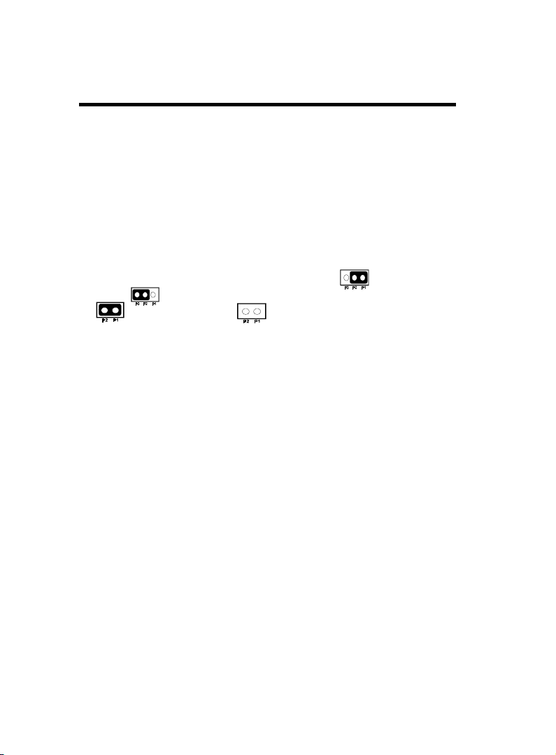
The jumper settings will be described numerically such as [----], [12], [2-3] for no connection, connect pins 1 & 2, and connect pins 2
& 3 respectively. Pin 1 for our mainboard is always on top one or
on the left when holding the mainboard with the keyboard away from
yourself. "P1" is written besides pin 1 on jumper with three pins.
The jumpers will also be shown graphically such as to connect
pin 1&2 and to connect 2&3. Jumpers with two pins will be
shown as for Short (on )and for Open (off).For manufacturing simplicity it may be sharing pins from other groups. Use the
diagrams in this manual instead of following the pin layout on the
board. Settings with two jumper numbers require that both jumpers
be moved together. To connect the pin, simply place a plastic jumper
cap over the two pins as diagrammed.
10 / Chapter 3 Installation
Page 5
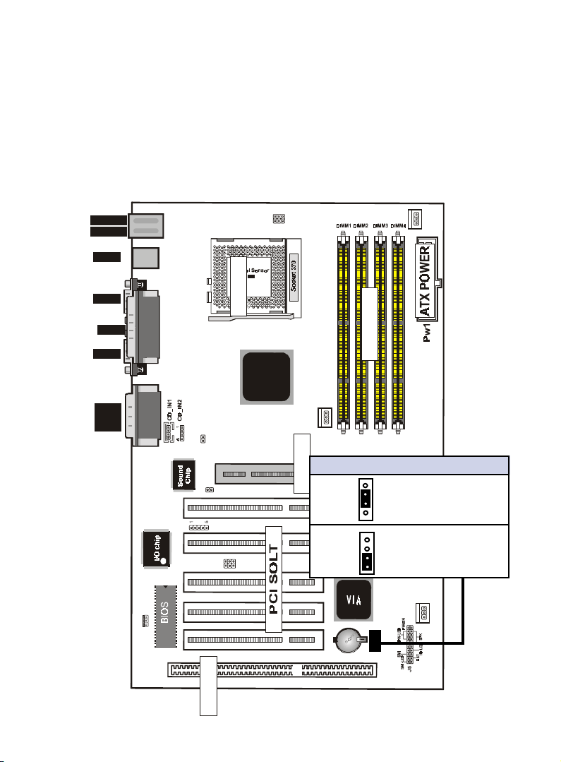
Real Time Clock (RTC) RAM - JP5 :
The CMOS RAM is powered by the onboard button cell battery. To
clear the RTC data:
(1)Turn off your computer, (2) Move this jumper to "3-4Pin Clear
Data", (3) Move the jumper back to "Default", (4) Turn on your
computer, (5) Hold down <Delete > during bootup and enter BIOS
setup to re-enter user Preferences.
1
down :
up
:Mouse
USB
K/B
JP6
JP7
1
FAN1
COM1
Printer
COM2
MIDI/
GAME/
AUDIO
SOCKET
DIMM
VIA
FAN2
JP1
JP5 CMOS Clear
AGP1
PCI1PCI2PCI3PCI5 PCI4
1
4
1
4
JP5
ISA SLOT1
IDE
1
Normal
FDC
FAN 3
1
J6
IR
2-3 (default)
AGP SOLT
3-4 Clear CMOS
J2
12
LAN
J3
ISA SOLT
Chapter3 Installation / 11
Page 6
System Memory ( DIMM Module)
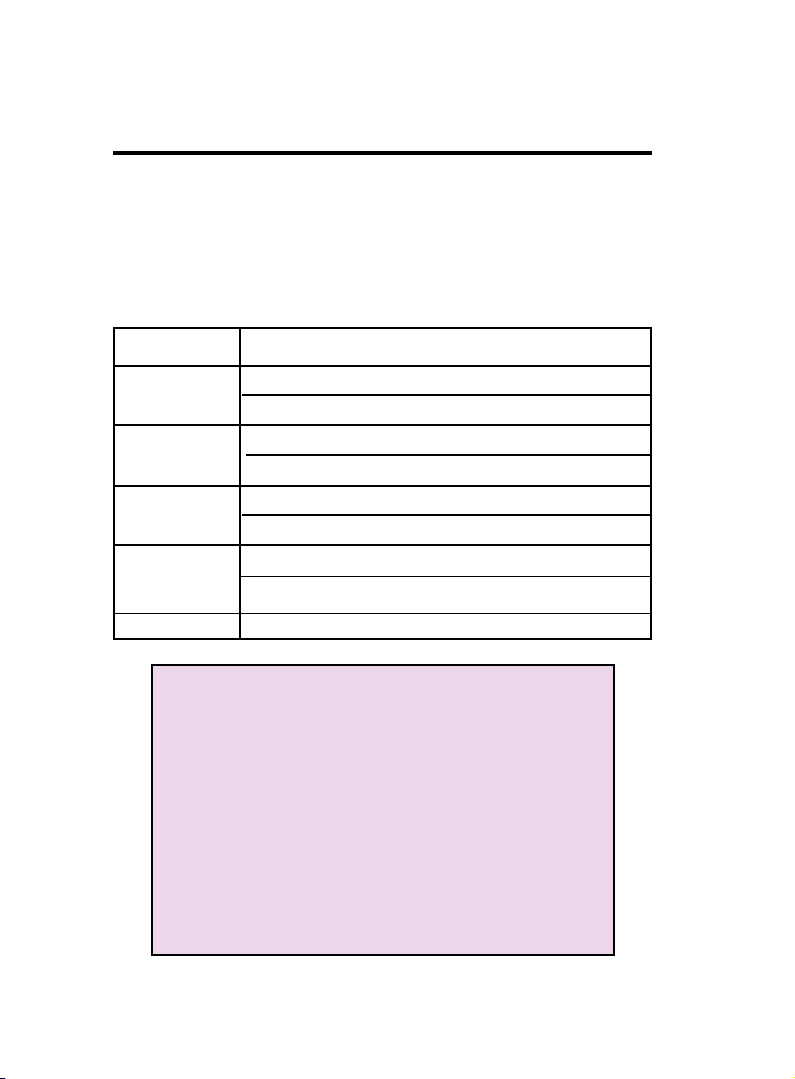
This 6VIA83 main board supports four 168 pins DIMM of 16 MB,
32 MB, 64 MB, 128 MB ,256MB to form a memory size between
16MB to 256MB.
The DRAM can be either 45ns,50ns,or 60ns 3.3v SDRAM,and 3.3v
Enhanced Data Output (EDO) RAM.
Install memory in any or all Banks in Combination:
Bank Memory module
DIMM 1 16MB,32MB,64MB,128MB,256MB
( Bank 0-1 ) 168 pin,3.3v SDRAM / EDO RAM
DIMM 2 16MB,32MB,64MB,128MB,256MB
( Bank 2-3 ) 168 pin 3.3v,SDRAM / EDO RAM
DIMM 3 16MB,32MB,64MB,128MB,256MB
( Bank 4-5 ) 168 pin 3.3v,SDRAM / EDO RAM
DIMM 4 16MB,32MB,64MB,128MB,256MB
( Bank 6-7 ) 168 pin 3.3v,SDRAM / EDO RAM
Total System Memory(Max 1024MB)
Note :
The DIMM Slot does not support any 5v EDO DIMM
module.
The DIMM Slot does not support any 5v SDRAM DIMM
module.
Memory speed setup is required through "Auto Con-
figuration" in BIOS chipset Setup of BIOS
SOFTWARE. If several speed memories are used, You
must set Auto Configuration to low. Example If both
50ns, 60ns are used, Please set Auto configuration to
60ns.
It's allowed any DIMM module put in any DIMM slot.
It's allowed there are different capacity DIMM module
in all DIMM slot.
12 / Chapter 3 Installation
Page 7
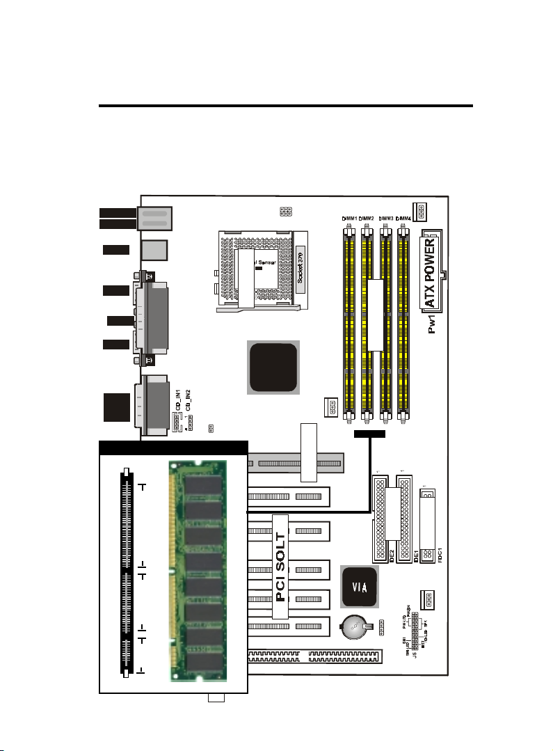
DIMM Memory Installation
Insert the module (s) as shown. Because the number pins are differ-
ent on either side of the breaks,the module will only fit in the orienta-
tion as shown. SDRAM DIMM modules have different pin contacts
on each side and therefore have a higher pin density.
1
down :
up
USB
K/B
:Mouse
JP6
JP7
1
FAN1
COM1
Printer
COM2
MIDI/
GAME/
AUDIO
JP1
168 Pin DIMM Socket
1
J6
88 pins
IR
60 pins
LAN
J3
20 pins
J2
12
SOCKET
VIA
DIMM
FAN2
AGP1
AGP SOLT
PCI1PCI2PCI3PCI5 PCI4
IDE
FDC
FAN 3
1
JP5
ISA SLOT1
ISA SOLT
Chapter3 Installation / 13
Page 8
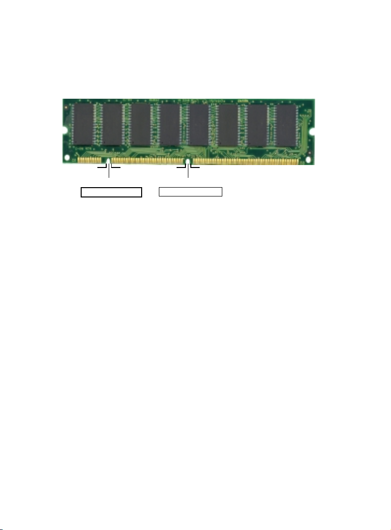
The Dual Inline Memory Module (DIMM) memory module must
be 3.3v Extended Data Output (EDO) DRAM or SDRAM. You can
identify the type of DIMM module by the illustration below:
RFU Unbuffered
Buffered
DRAM Key Position
5.0V Reserved
3.3V
Voltage Key Position
168 Pin DRAM DIMM Notch Key Definitions
The notch on the DIMM module will shift between left, center, or
right to identify the type and also to prevent the wrong type to be
inserted into the DIMM slot on the Mainboard. You must ask your
retailer for Specifications before purchasing.
Four clock signals are supported on this mainboard
14 / Chapter 3 Installation
Page 9
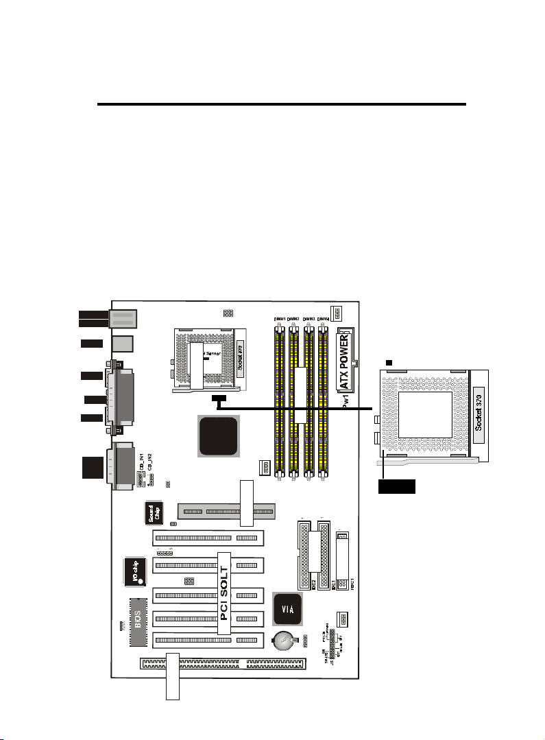
CPU Installation
The motherboard provides a ZIF socket 370. The CPU that came
with the motherboard should have a fan attached to it to prevent
overheating . If this is not the case then purchase a fan before you
turn on your system.
To install a CPU , first turn off your system and remove its cover.
Locate the ZIF socket and open it by first pulling the lever sideways
away from the socket then upwards to a 90-degree right angle. Insert the CPU with the correct orientation shown . The notched corner should point towards the end of the lever. Because the CPU has
a corner pin for two of the four corners, the CPU will only fit in the
orientation as shown.
1
down :
up
:Mouse
USB
K/B
JP6
JP7
1
FAN1
COM1
Printer
COM2
MIDI/
GAME/
AUDIO
SOCKET
DIMM
VIA
FAN2
JP1
1
J6
IR
J2
12
LAN
J3
ISA SOLT
AGP1
AGP SOLT
PCI1PCI2PCI3PCI5 PCI4
IDE
FAN3
1
JP5
ISA SLOT1
Chapter3 Installation / 15
Notch
FDC
Page 10

Selecting the CPU Frequency
CPU voltage auto-detection and allow user to set CPU frequency
through BIOS setup, no jumper or switch is needed. The correct
CPU information is saved into EPROM, with these technologies,
the disadvantages of Pentium base jumper-less design are eliminated.
There will be no worry of wrong CPU voltage detection and no need
to re-open the housing if CMOS battery loss. The CPU frequency
selection is set by going into:
Choose “CPU SPEED SETTING” from the Main Menu and a screen
with a list of items appears.
CPU Speed
Set to Manual user can use the next two items to decide the
CPU speed.
CPU Ratio
This item lets you select the ratio of Core/Bus frequency. Have
the following selection: 3x, 3.5x, 4x, 4.5x, 5x, 5.5x, 6x, 6.5x, 7.
0x, 7.5x,8
CPU Freqency
This item lets you set external clock (bus clock). The possible
settings are 66,100 and 133 MHZ....
Clearance Requirements
To maintain proper airflow once the processor is installed on the
mainboard, the processor and fan heatsink require certain space
clearances. The clearance above the processor must be at least 0.3
inches. The clearance on at least 3 of 4 sides of the processor and
fan heatsink must be at least 0.2 inches. All cables (for Floppy drive,
Hard drive,CD-ROM,and so on) must be routed clear of the processor and its airspace.
Fan Exhaust
The processor must be kept cool by using a processor with heatsink
and fan attached . The temperature of the air filled with the fan/
heatsink cannot exceed 45 OC(113 OF ) . The ambient or room temperature must be below 37 OC ( 99 OF) .
16 / Chapter 3 Installation
Page 11
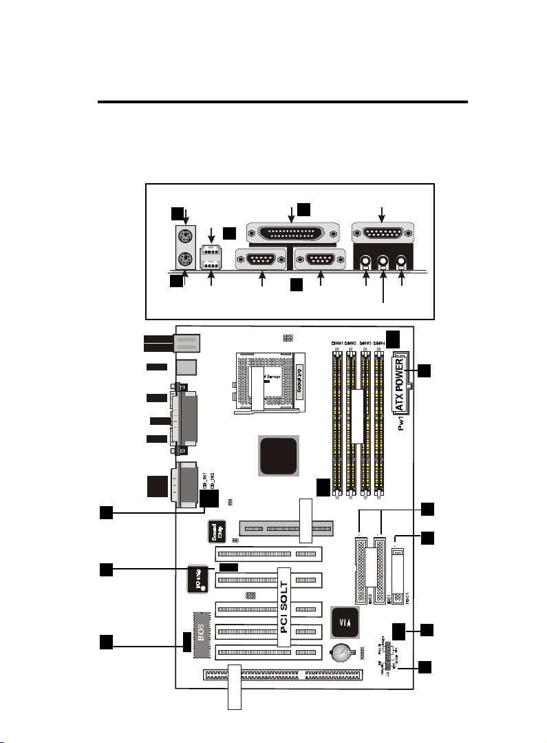
EXTERNAL CONNECTORS
Serial Port(9-pin Male)
Serial
Port(9-pin Male)Serial Port(9-pin Male)
Serial
Port(9-pin Male)
LINE IN
LINE
INLINE IN
LINE
IN
Parallel (Printer) Port
Parallel
(Printer) PortParallel (Printer) Port
Parallel
(Printer) Port
MIDI/(GAME) Port
MIDI/(GAME)
PortMIDI/(GAME) Port
MIDI/(GAME)
Port
Both Ribbon cable and Connectors on board are with direction signs
to avoid that user insert wrong directions. On other hand, the ribbon
cables should always be connected with the red stripe on the pin 1
of side of the connector.
PS/2 Mous e
PS/2 Mous e
PS/2 Mous ePS/2 Mous e
2
USB1
USB1
USB1USB1
(25-pin Female)
(25-pin Female)
(25-pin Female)(25-pin Female)
4
5
(15-pin Female)
(15-pin Female)
(15-pin Female)(15-pin Female)
12
CD Audio
Connector
9
IR Port
13
Wake On
LAN
PS/2 Keyb oard
PS/2 Keyb oard
PS/2 Keyb oardPS/2 Keyb oard
(6-pin Female)
(6-pin Female)
(6-pin Female)(6-pin Female)
K/B
down :
:Mouse
up
USB
COM1
Printer
COM2
MIDI/
GAME/
AUDIO
1
USB2
USB2
USB2USB2
COM1
COM1
COM1COM1
3
COM2
COM2
COM2COM2
SPEAKER
SPEAKER
1
JP6
JP7
1
SPEAKERSPEAKER
MIC
MIC
MICMIC
FAN1
11
ATX Power
FDC
FAN 3
Connector
8
IDE Connector
6
Floppy
Driver Connector
FAN 1,2,3
7
Connector
PANEL
10
SOCKET
DIMM
VIA
JP1
1
J6
IR
J2
12
LAN
J3
FAN2
AGP1
AGP SOLT
PCI1PCI2PC I3PCI5 PCI4
IDE
1
JP5
ISA SLOT1
ISA SOLT
Chapter3 Installation / 17
Page 12
1. PS/2 Keyboard port
This connection is for a standard keyboard using an PS/2 plug
(mini DIN) . This connector will not allow standard at AT size
(large DIN) keyboard plugs. You may use a DIN to mini DIN
adapter on standard AT keyboards.
2. PS/2 Mouse port
This system will direct IRQ12 to PS/2 mouse.
3. Serial Port COM 1 and COM 2 port
The two serial ports can be used for pointing devices or other
serial devices. See "Onboard Serial Port" in chipset Feature Setup
of the BIOS SOFTWARE.
NOTE:
Serial {D-type 9pin (F) } must be connected to the
serial port.
4. Parallel Printer port
You can enable the parallel port and choose the IRQ through "
Onboard Parallel Port" in Chipset. Feature Setup of the BIOS
SOFTWARE.
5. Universal Serial BUS Ports 1 & 2
Two USB ports are available for connecting USB devices.
6. Floppy drive connector
This connector supports the provided floppy drive ribbon cable.
After connecting the single end to the board, connect the two
plus on the other end to the floppy drives.
18 / Chapter 3 Installation
Page 13
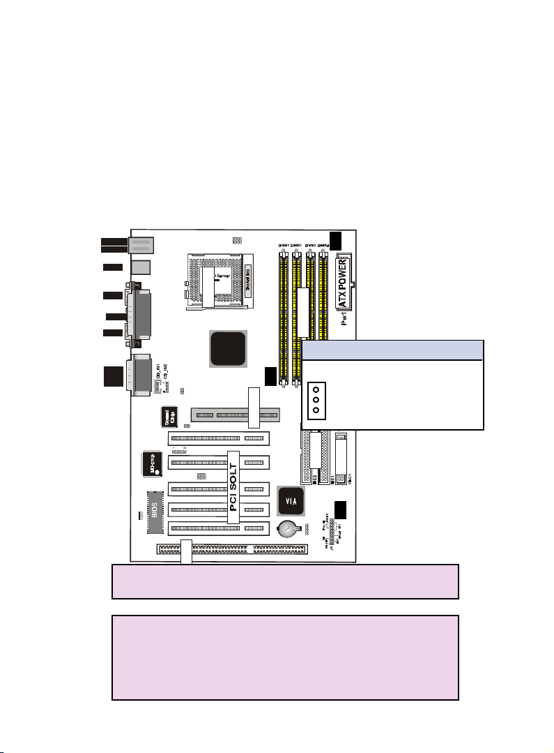
7. FAN1 , FAN2 , FAN3 CPU Cooling Fan (FAN/PWR)
These connectors support cooling fans of 500mAmp
(6Watt) or less. Orientate the fans so that the heatsink
fins allow airflow to go across the onboard heat sink(s)
instead of the expansion slots. Depending on the fan
manufacturer, the wiring and plug may be different. The
red wire should be positive, while the black should be
ground. Connect the fan’s plug to the board taking into
consideration the polarity of this connector.
1
down :
up
:Mouse
USB
K/B
JP6
JP7
1
FAN1
COM1
Printer
COM2
MIDI/
GAME/
AUDIO
LAN
J3
SOCKET
DIMM
VIA
JP1
1
J6
IR
J2
12
FAN2
AGP SOLT
FAN1/2/3 CPU Cooling FAN
Pin Description
1 Ground
P1
P2
2 +12VDC
JP5
ISA SLOT1
P3
3 Signal
IDE
FDC
FAN3
1
AGP1
PCI1PCI 2PCI3PCI5 PCI4
NOTE :
The "Rotation" signal is to be used only by a specially
ISA SOLT
designed fan with rotation signal.
WARNING :
The CPU and/or motherboard will overheat if there is
no air flowing across the CPU and onboard heatsinks.
Damage may occur to the motherboard and/or the CPU
fan if these pins are incorrectly used. These are not
jumpers, do not place jumper caps over these pins.
Chapter3 Installation / 19
Page 14
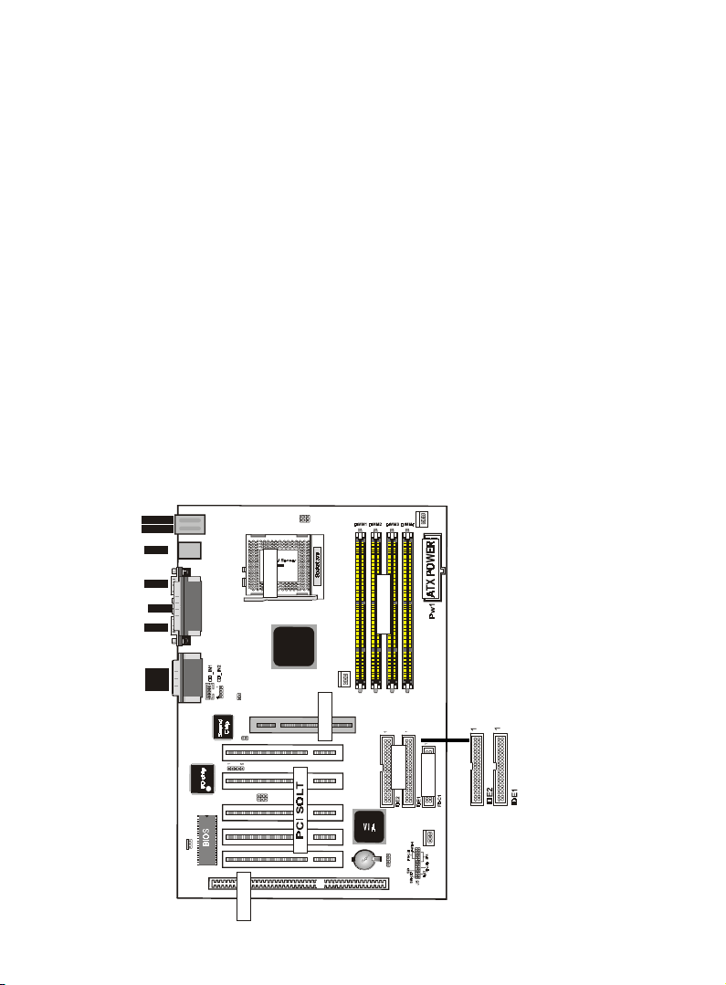
8. Primary / Secondary IDE connectors (Two 40-pin Blocks)
These connectors support the provided IDE hard disk ribbon
cable. After connecting the single end to the board, connect the
two plugs at the other end to your hard disk no space(s) . If you
install two hard disks, you must configure the second drive to
Slave mode by setting its jumper settings. BIOS now supports
SCSI device or IDE CD-ROM boot up (see "HDD Sequence SCSI/
IDE First" & "Boot Sequence" in the BIOS Features Setup of the
BIOS SOFTWARE) (Pin 20 is removed to prevent inserting in
the wrong orientation when using ribbon cables with pin 20
plugged) .
Tip :
You may configure two hard disks to be both Masters
using one ribbon cable on the primary IDE connector.
You may install one operating system on an IDE drive
and another on a SCSI drive and select right one the
through BIOS Feature Setup.
1
down :
up
:Mouse
USB
K/B
JP6
JP7
1
FAN1
COM1
Printer
COM2
MIDI/
GAME/
AUDIO
JP1
1
J6
IR
2
J2
1
LAN
J3
ISA SOLT
20 / Chapter 3 Installation
SOCKET
DIMM
VIA
FAN2
AGP1
AGP SOLT
PCI1PCI2PCI3PCI5 PCI4
IDE
FDC
FAN3
1
JP5
ISA SLOT1
Page 15
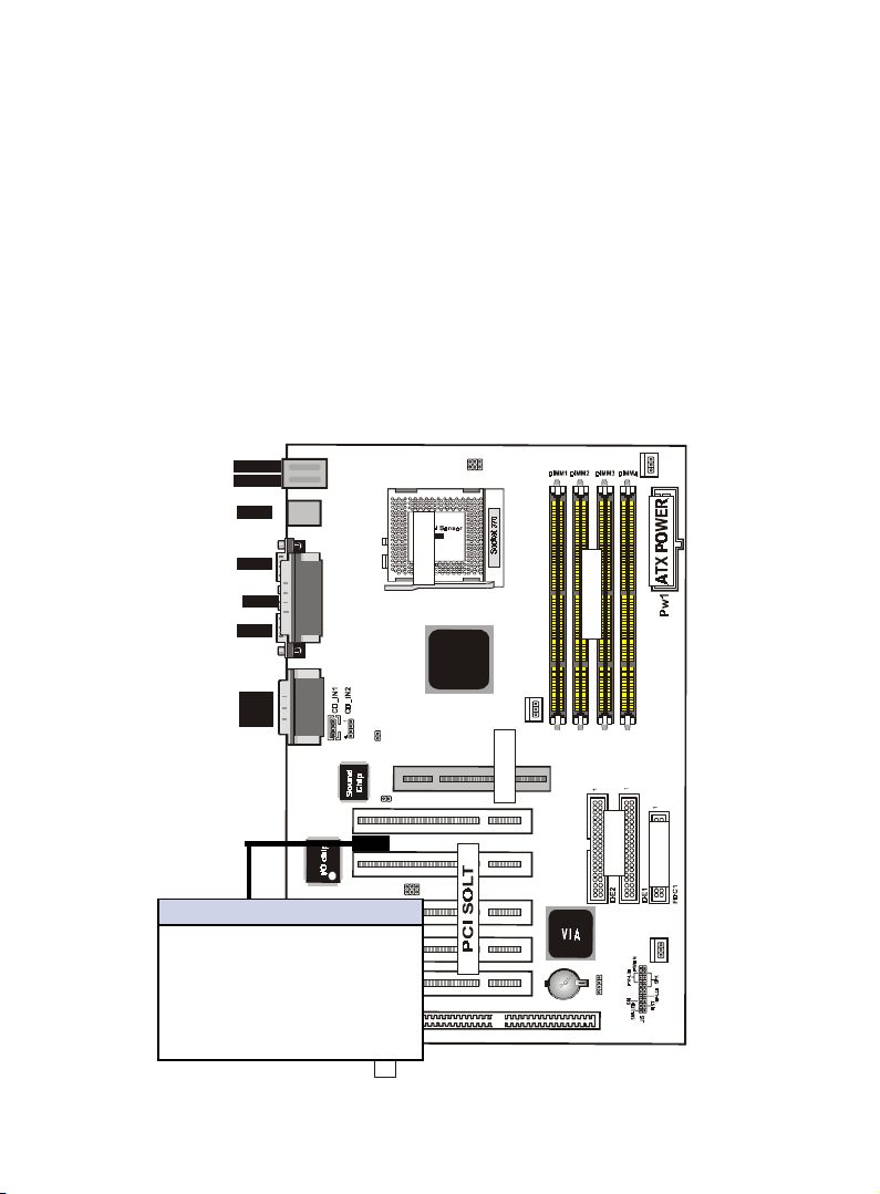
9. IrDA / Fast IR-Compliant infrared module connector - IR(J1)
This connector supports the optional wireless transmitting and
receiving infrared module. This module mounts to a small opening on system cases that support this feature. You must also
configure the setting through UART2 Use Infrared” in Chipset
Feature Setup to select whether UART2 is directed for use with
COM2 or IrDA. Use the five pins as shown on the Back View
and connect a ribbon cable from the module to the motherboard
according to the pin definitions.
1
down :
up
:Mouse
USB
K/B
JP6
JP7
1
FAN1
COM1
Printer
COM2
MIDI/
GAME/
AUDIO
IrDA/Fast IR Connector
Pin Description
1 VCC
2 Option
3 IRRX2
4 Ground
5 IRTX2
LAN
SOCKET
DIMM
VIA
JP1
1
J6
IR
J2
12
J3
FAN2
AGP1
AGP SOLT
PCI1PCI2PCI3PCI5 PCI4
IDE
FDC
FAN3
1
JP5
ISA SLOT1
ISA SOLT
Chapter3 Installation / 21
Page 16
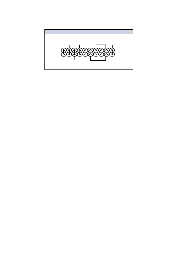
10.J5
J5 PANEL Connector
RST
HD_LED
-
-
-
SMI LED
SMI
PW_BN
PW_LED
+
1
+
SPEAK
2
a. IDE activity LED (HD-LED)
This connector supplies power to the cabinet’s IDE activity LED.
Read and write activity by devices connected to the Primary or
Secondary IDE connectors will cause the LED to light up.
b. Power LED Lead (PW_LED)
The system power LED lights when the system’s power is on.
c.SMI Suspend Switch Lead (SMI)
This allows the user to manually place the system into a suspend
mode or “Green” mode where systematic activity will be instantly decreased to save electricity and expand the life of certain components when the system is not in use. This 2-pin connector (see the figure below) connects to the case-mounted suspend switch. If you do not have a switch for the connector, you
may use the “Turbo Switch” since it does not have a function.
SMI is activated when it detects a short to open moment and
therefore leaving it shorted will not cause any problems. It may
require one or two pushes depending on the position of the
switch. Wake-up can be controlled by settings in the BIOS but
the keyboard will always allow wake-up (the SMI lead cannot
wake-up the system). If you want to use this connector,"Suspend
Switch" in the Power Management Setup of the BIOS SOFTWARE section should be on the default setting of Enable
d. Reset Switch Lead (RST)
This 2-pin connector connects to the case-mounted reset switch
for rebooting your computer without having to turn off your
power switch. This is a preferred method of rebooting in order
to prolong the life of the system's power supply.
22 / Chapter 3 Installation
Page 17
e. Speaker Connector (SPEAKER)
This 4-pin connector connects to the case-mounted speaker.
f. ATX Power Switch (PW_BN)
The system power is controlled by a momentary switch connected to this lead. Pushing the button once will switch the system ON. The system power LED lights when the system's power
is on
11. ATX Power Supply Connector (20-pin block) - PW1
This connector connects to a ATX power supply. The plug from
the power supply will only insert in one orientation because of
the different hole sizes. Find the proper orientation and push
down firmly making sure that the pins are aligned.
IMPORTANT:
Make sure that the ATX power supply can take at least
10mAmp load on the 5Volt standby lead (5VSB). You may
experience difficulty in powering on your system without this.
Pin Description Pin Description
1 3.3V 2 3.3V
3 GND 4 5V
5 GND 6 5V
7 GND 8 PW-OK
9 5VSB 10 12V
11 3.3V 12 -12V
13 GND 14 PS-ON
15 GND 16 GND
17 GND 18 -5V
19 5V 20 5V
Chapter3 Installation / 23
Page 18
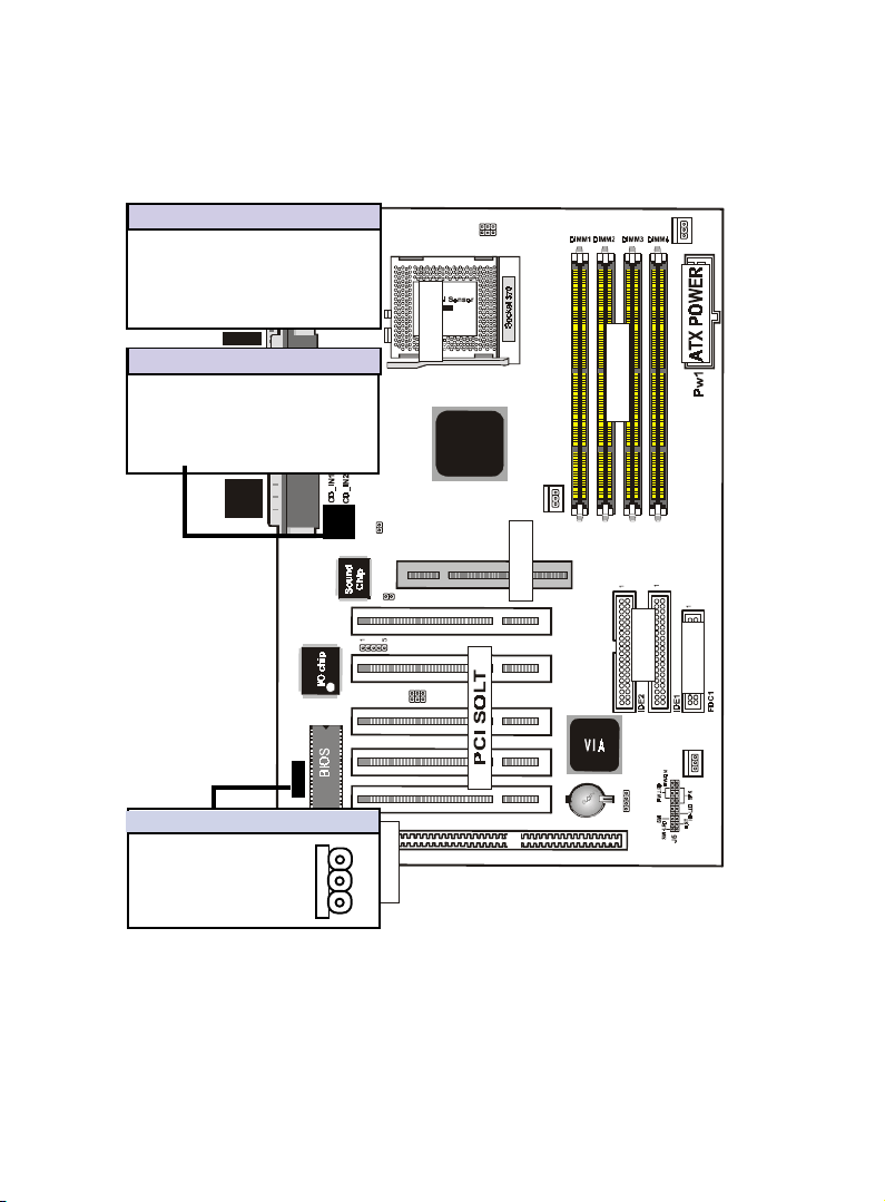
12. CD Audio Connector- CD_IN1/CD_IN2
The 4-pin connectors enable the system to receive the audio
output from the CD-ROM.
CD_IN1 Description
1 CD-R
2 GND
3 CD-L
down :
up
K/B
:Mouse
USB
4 GND
COM1
CD_IN2 Description
1 CD-R
2 GND
Printer
COM2
3 GND
4 CD-L
MIDI/
GAME/
AUDIO
JP1
1
JP6
JP7
1
SOCKET
DIMM
VIA
FAN2
FAN1
AGP1
AGP SOLT
PCI1PCI2PCI3PCI5 PCI4
JP5
ISA SLOT1
LAN
J3
Wake-On-LAN Connector
Pin Description
1 5VSB
2 GND
3 SENSOR
1
J6
IR
J2
12
P1
ISA SOLT
P3
13. Wake Up On LAN : J3
This connector connects LAN cards and a Wake On LAN output.
When the system is in soft-off mode LAN activity will power
on the system.
24 / Chapter 3 Installation
IDE
FDC
FAN3
1
Page 19
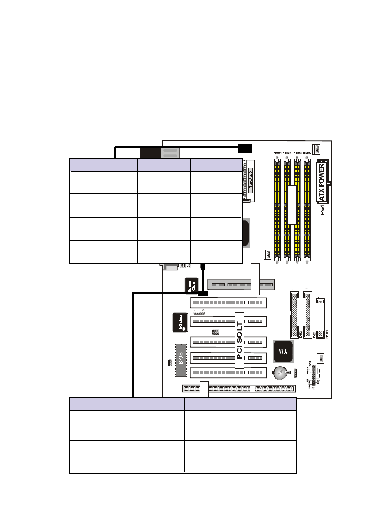
14.CPU Type Selection -JP6,JP7
Current PCI bus in limited to 33MHz, socket370 Celeron proces-
sors limited to 66MHz, and SDRAM limited to the DIMM type 66/
100/133MHz. Other settings are for experienced users only.
1
K/B
down :
:Mouse
up
Bus_FREQ JP7 JP6
USB
Auto detect
COM1
66MHZ
test only
66 to 100MHZ Not Conn.
Printer
COM2
test only
100 to 133MHZ Not Conn. Not Conn.
test only
MIDI/
GAME/
AUDIO
JP1
JP6
JP7
1
FAN1
SOCKET
DIMM
VIA
FAN2
1
J6
IR
J2
12
LAN
J3
Onboard sound Function JP1 J 6
ISA SOLT
AGP SOLT
Enabled (Colse]
Disenabled [Open]
15. Onboard sound chip disable jumper : JP1,J6
Chapter3 Installation / 25
AGP1
PCI1PCI2PC I3PCI5 PCI4
IDE
FDC
FAN 3
1
JP5
ISA SLOT1
 Loading...