

Page 1

Contents Motherboard 7KT400A
Motherboard
7KT400A
1. 7KT400A Specifications....................4
1.1 Introduction ............................................................ 4
1.2 Package Contents .................................................. 5
1.3 Specifications and Features .................................. 6
CPU Processor ........................................................................... 6
Chipset ........................................................................................ 6
PCI ..............................................................................................6
DDR SDRAM Memory ............................................................... 6
..................................................................................................... 6
Universal Serial Bus .................................................................. 6
AGP ............................................................................................. 6
WOL (Wake On LAN) ................................................................ 6
Award BIOS ................................................................................ 7
ATA 133 On Board ..................................................................... 7
PC’99 Color-coded I/O Ports ...................................................... 7
Hardware Monitoring in Chip W83697HF ................................7
1.4 7KT400A Layout Diagram ................................... 8
1.5 CPU Installation ................................................... 10
CPU Installation Procedures for Socket 462 ...........................10
1.6 DDR SDRAM Installation ................................. 11
1.7 Connectors & Jumpers Setting ........................... 12
1.7.1 Back Panel I/O Connectors .............................................12
1.7.1.1 PS/2 Mouse / Keyboard CONN: .............................................. 1 2
0-1
Page 2

Contents Motherboard 7KT400A
1.7.1.2 USB0/1/2/3 ..................................................................................... 1 2
1.7.1.3 Serial Interface Port: COM1/2 ............................................... 1 3
1.7.1.4 Parallel Interface Port .............................................................. 1 3
1.7.1.5 Audio Ports ................................................................................... 1 3
1.7.2 ATX Main Power Connectors: ATXPWR .......................14
1.7.3 Floppy Disk Connector: FDD .......................................... 15
1.7.4 Hard Disk Connectors: IDE1/IDE2 ................................15
1.7.5 Fan Connectors: FAN1/CPUFAN/SYSFAN ..................... 15
1.7.6 CD Audio-In Connectors: CDIN1 .................................... 16
1.7.7 IR infrared module: IR/CIR Connector .......................... 16
1.7.8 USB Pin Header: USB4/5 ................................................ 17
1.7.9 Front Panel Connectors: PANEL1 .................................. 18
1.7.10 Wake On LAN Connector: WOL ..................................20
1.7.11 Game/MIDI Connector: J1 .............................................20
1.7.12 Smart Panel Connectors (optional): .............................. 21
1.7.12.1 Front COM2 Header Connector: COM2 .......................... 2 1
1.7.12.2 Audio/Mic Auto Connector: JP1 .......................................... 2 1
1.7.12.3 SPII Printer Error LED Port: SP-J6 ..................................... 2 2
1.7.12.4 Second BIOS Connector: SP-J2 .......................................... 2 2
1.7.12.5 6-channel SP-DIF Audio Connector: J6 ............................ 2 3
1.7.13 CMOS Function Selector: Clear_CMOS .....................24
1.7.14 USB4/5 Wake-up Selector: J4 ......................................24
1.7.15 CPU Clock Frequency Selector: J3 & J5 ..................... 25
1.7.16 Ports USB0/1, 2/3 Wake-up Selector : J2 ....................26
2. BIOS Setup ..................................... 27
2.1 BIOS Support ....................................................... 27
2.2 Main Menu .......................................................... 30
0-2
Page 3

Contents Motherboard 7KT400A
2.3 Standard CMOS Features .................................. 33
2.4 Advanced BIOS Features ................................... 37
2.5 Advanced Chipset Features ................................ 41
2.6 Integrated Peripherals ......................................... 48
2.7 Power Management Setup .................................. 55
2.8 PnP/PCI Configurations ....................................... 61
2.9 PC Health Status ................................................. 64
2.10 Frequency/Voltage Control ............................... 65
2.11 Load Fail-Safe Defaults..................................... 66
2.12 Load Optimized Defaults ................................... 67
2.13 Set Supervisor / User Password ........................ 68
2.14 Save & Exit Setup ............................................. 69
2.15 Exit Without Saving ........................................... 70
3. Drivers & Utilities ........................... 71
3.1 Auto-run Menu .................................................... 71
3.2 Installing VIA Service Pack ................................ 72
3.3 Installing Audio Driver ........................................ 75
3.4 Installing USB 2.0 Driver .................................... 77
Appendices .......................................... 79
Appendix I Quick Jumper Setup ............................ 79
Appendix II Mainboard Test Report ..................... 80
0-3
Page 4

Chapter 1 Motherboard 7KT400A
Chapter 1
Motherboard 7KT400A
1. 7KT400A Specifications
1.1 Introduction
The 7KT400A motherboard is an integration of AMD
Athlon/Duron CPU in Socket 462 packaging and the North
Bridge VIA KT400A (VT8377A) supporting 100/133/166
MHz Front Side Bus.
North Bridge KT400A on board also supports DDR 200/
266/333/400 SDRAMs, while the South Bridge VT8235 provides stable supports of ULTRA ATA 133, 6-channel Audio
playback and USB 2.0/1.1 interface.
The resulting architecture will provide an ideal multi-task
environment to support operating systems such as MS-DOS,
Windows, Windows NT , Windows ME, Windows 2000, Novell,
OS/2, Windows 95/98, Windows 98SE, Windows XP, UNIX,
Liunx, SCO UNIX etc. This user-friendly manual is to describe in detail how to install, configure and use this
motherboard with drivers and BIOS setup illustrations.
This manual is a general reference of the first release of this
motherboard which is subject to update without notice. If any difference is found between this manual and the motherboard you are
using, please visit our Web Site.
1-4
Page 5

Chapter 1 Motherboard 7KT400A
1.2 Package Contents
HDD UDMA66/100 Cable x1.
FDD Cable.
Flash Memory with BIOS.
I/O Shielding
Fully Setup Driver CD with built in utilities.
User Manual.
1-5
Page 6

Chapter 1 Motherboard 7KT400A
1.3 Specifications and Features
CPU Processor
| Support 100/133/166 MHz System Interface speed
| Single Socket 462 for AMD TM Athlon CPUs 700MHz~3000+
or higher*, and Duron CPUs 600 ~ 1400 MHz or higher*
* The higher frequency CPU should be compatible with AMD CPU
specificiation and the motherboard latest BIOS version which will
be released in our Web Site.
Chipset
| VIA KT400A North Bridge
| VIA VT8235 South Bridge
PCI
| Supports 5 x PCI slots, 32-bit 33MHz PCI Bus speed.
DDR SDRAM Memory
| Supporting 64/128/256/512/1G....MB DDR module in 3 slots
| Supporting 400/333/266/200MHz DDR SDRAM
| Supporting a maximum memory size of 3GB of DDR SDRAM
Universal Serial Bus
| Supporting two on-board Universal Serial Bus(USB)Ports
and four external Universal serial Bus(USB)Ports.
| Supporting USB 2.0/1.1
AGP
| Supporting 1 x AGP8X slot, V3.0 compliant.
WOL (Wake On LAN)
| Supporting system power-on by LAN Ring-up signal.
1-6
Page 7

Chapter 1 Motherboard 7KT400A
Award BIOS
| Supporting Plug & Play specification which detects the
peripheral devices and expansion cards automatically
| Supporting CD-ROM, SCSI, LAN BOOT, Temperature sen-
sor, LAN, Alarm Bus CLK setup
| Supporting Desktop Management Interface (DMI) func-
tion for recording mainboard specification
ATA 133 On Board
| Supporting PIO Mode 5, Master Mode, high performance
hard disk drives.
| Supporting Ultra DMA 33/66/100/133 Bus Master Mode.
| Supporting 4xIDE devices, including CD-ROM, CD-R, CD-RW,
LS-120 and high capacity hard disk drives with LBA mode
PCI-Based AC 97 Digital Audio Processor
| AC 97 2.2 compatible Codec, 6-channel Audio interface.
| 18-bit Stereo Full-Duplex Codec with up to 48 KHz samp-
ling rate
| 4 Analog Line-level Stereo inputs for connection from Line,
CD, Viedo and AUX
| 2 Analog Line-level Stereo inputs for speakerphone and PC
beep
PC’99 Color-coded I/O Ports
| 6 USB ports, USB 2.0 compliant.
| 2 COM ports; 1 Parallel port
| 1 PS/2 Mouse port; 1 PS/2 Keyboard port
| 1 Line-in; 1 Line-out; 1 Mic
Hardware Monitoring in Chip W83697HF
| Core voltage, CPU temperature and Fan speed monitoring
1-7
Page 8
Chapter 1 Motherboard 7KT400A
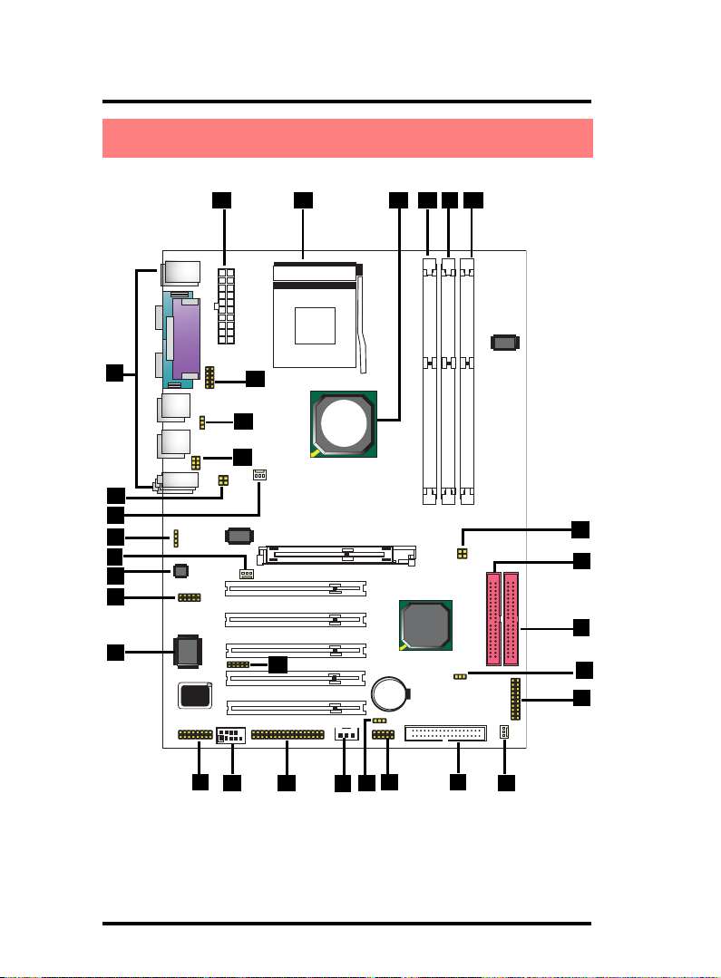
1.4 7KT400A Layout Diagram
24 2223
2627
25
Socket 462
1
29
28
VIA
KT400A
30
2
3
4
5
7
8
W83697
BIOS
9610
8100BL
RTL
31
AGP 8X Slot
PCI 1
PCI 1
PCI 1
PCI 1
PCI 1
12
VIA
VT8235
Battery
13 1411
15 16
21
20
19
18
17
1-8
Page 9

Chapter 1 Motherboard 7KT400A
7KT400A Component Layout :
1. Back Panel: Back Panel I/O Connectors ( Mouse, Keyboard, COM1,
COM2, Printer, Mic in, Line in, Speaker-out, USB0/1/2/3)
2. J3: CPU clock Frequency Connector
3. CPUFAN1: CPU Fan Connector
4. VOIN1: CD Audio In Connector
5. FAN1: Cooling Fan Connector
6. ALC650: AC’97 Audio Codec
7. J6: Connector for 6-channel SP-DIF Audio (optional)
8. W83697HF: Winbond I/O chip
9. J1: Game Port/MIDI Connector
10. COM2 Header: Pin Header for an external COM Port
11. SP-J2: BIOS2 Connector
12. WOL: Wake-on LAN Connector
13. J4: USB4/5 Power Option
14. USB4/5: USB Header for 2 USB Ports
15. FDD: Floppy Drive Connector
16. SYSFAN1: System Cooling Fan Connector
17. Panel1: Front Panel Connector
18. Clear CMOS: Jumper for clearing CMOS
19. IDE2: IDE Connector
20. IDE1: IDE Connector
21. J5: CPU Clock Frequency Connector
22. DIM3: DDR SDRAM Slot
23. DIM2: DDR SDRAM Slot
24. DIM1: DDR SDRAM Slot
25. VIA KT400A: North Bridge
26. Socket 462: CPU socket for AMD CPUs
27. ATXPWR: ATX Main Power Connector
28. SP-J6: Printer Error LED Connector for Smart Panel Connection
29. J2: Jumper for USB0/1, 2/3 Power Option
30. JP1: Audio connector for Smart Panel connection
31. IR/CIR: IR/CIR Connector for Infrared Signal Transmission/Re
ception
1-9
Page 10
Chapter 1 Motherboard 7KT400A
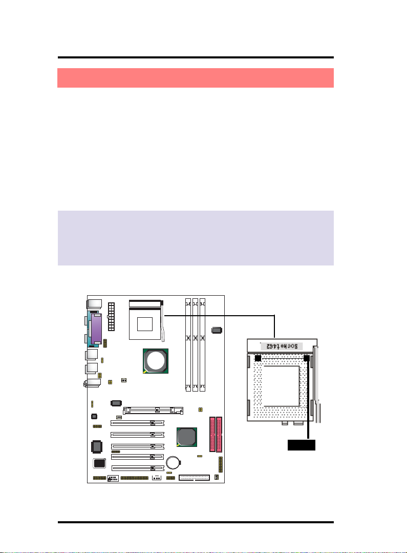
1.5 CPU Installation
The motherboard operates with Socket 462 for AMD Athlon
and Duron
TM
processor. The CPU should always have a Heat Sink
and cooling fan attached to prevent overheating.
CPU Installation Procedures for Socket 462
1. Pull the lever sideways away from the socket then raise the
lever to a 90-degree angle.
2. Locate Pin 1 in the socket and look for the white dot or cut edge
in the CPU. Match Pin 1 with the white dot/cut edge then
insert the CPU.
3. Press the lever down to complete the installation.
4. Make sure the spec of the cooling fan is good enough.
5. Please lock the fan on CPU very carefully, or you will damage
the resistor array even circuit line on the mainboard.
Socket 462
VIA
KT400A
TM
BIOS
W83697
8100BL
RTL
VIA
VT8235
Notch
1-10
Page 11
Chapter 1 Motherboard 7KT400A
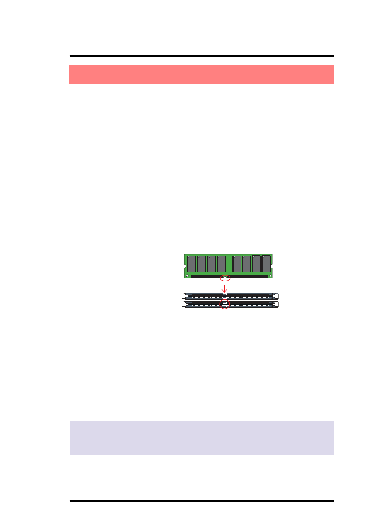
1.6 DDR SDRAM Installation
The motherboard supports a maximized 3GB memory. It provides three 184-pin unbuffered DDR sockets and each supports
64MB to 1GB DDR memory module.
DDR SDRAM Installation Procedures:
1. The DDR socket has a “Plastic Safety Tab” and the DDR memory
module has an asymmetrical notch”, so the DDR memory module can only fit into the slot in one direction.
2. Push the tabs out. Insert the DDR memory modules into the
socket at a 90-degree angle then push down vertically to fit
onto place.
3. The Mounting Holes and plastic tabs should fit over the edge
and hold the DDR memory modules in place.
184-pin DDR Module
DDR Module Notch
DDR Module Rib
Note:
When you plug or unplug DDR module, you must check your
power supply is OFF.
1-11
Page 12
Chapter 1 Motherboard 7KT400A
1.7 Connectors & Jumpers Setting
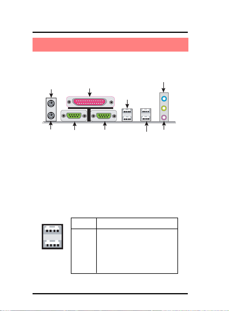
1.7.1 Back Panel I/O Connectors
This motherboard provides the following back panel
connectors:
PS/2 Mouse
Parallel(Printer) Port
25-pin female
USB0
USB1
Speaker
PS/2 Keyboard
(6-pin female)
COM1
COM2
USB2
USB3
Line-in
Mic
1.7.1.1 PS/2 Mouse / Keyboard CONN:
The motherboard provides a standard PS/2 mouse / Keyboard
mini DIN connector for attaching a PS/2 mouse. You can plug a
PS/2 mouse / Keyboard directly into this connector.
1.7.1.2 USB0/1/2/3
The motherboard provides a OHCI(Universal Host Controller
Interface) & EHCI (Enhance Host Controller Interface)Universal
Serial Bus Roots for connecting USB devices such as a
keyboard, mouse and other USB devices.
USB Pin Signal
1 +5V_SB
2 USBP0-(USBP1-/2-/3-)
3
12
4
USB0/1/2/3
3 USBP0+(USBP1+/2+/3+)
4 GND
1-12
Page 13
Chapter 1 Motherboard 7KT400A
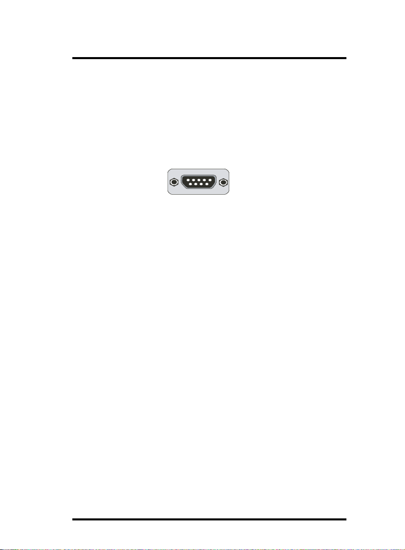
1.7.1.3 Serial Interface Port: COM1/2
The serial interface port is sometimes referred to as an RS232 port or an asynchronous communication port. Mice,
printers, modems and other peripheral devices can be
connected to a serial port. The serial port can also be used
to connect computer systems together . If you like to transfer
the contents of your hard disk to another system, it can be
accomplished with serial port.
COM1/2
1.7.1.4 Parallel Interface Port
Unlike serial ports, parallel interface ports have been
standardized and should not present any difficulty interfacing
peripherals to your system. Sometimes called a Centronics
port, the parallel port is almost exclusively used with printers.
The parallel port on your system is a 25-pin, DB 25 connector.
1.7.1.5 Audio Ports
Speaker out is a connector for Speakers or Headphones.
Line in is used for external CD player, Tape player, or other
audio devices. Mic is a connector for the microphones.
1-13
Page 14
Chapter 1 Motherboard 7KT400A
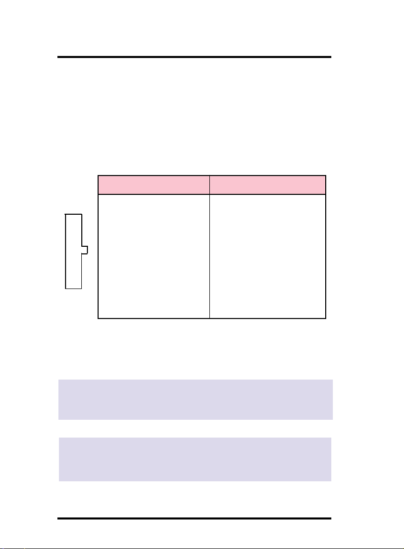
1.7.2 ATX Main Power Connectors: ATXPWR
This connector supports the power button on-board. Using
the ATX power supply, functions such as Modem Ring WakeUp and Soft Power Off are supported on this motherboard .
This power connector supports instant power-on
functionality, which means that the system will boot up
instantly when the power connector is inserted on the board.
ATX 4-pin power connector only support +12V voltage.
Pin Signal Pin Signal
20
11011
1 3.3V 11 3.3V
2 3.3V 12 -12V
3 GND 13 GND
4 5V 14 PS-ON
5 GND 15 GND
6 5V 16 GND
7 GND 17 GND
8 PW-OK 18 -5V
9 5V_SB 19 5V
10 12V 20 5V
Note:
When you set up P4 power supply, both PW1 and PW2 must
be connected to power.
Important:
To switch on your power supply, please make sure:
1. Memory Module is properly installed.
2. Power supply setup is OK.
1-14
Page 15
Chapter 1 Motherboard 7KT400A
1.7.3 Floppy Disk Connector: FDD
This connector supports the provided floppy drive ribbon
cable. After connecting the single end to the board, connect
the two plugs on the other end to the floppy drives.
1.7.4 Hard Disk Connectors: IDE1/IDE2
These connectors are provided with IDE hard disk ribbon
cable into the package . After connecting the end of cable
with single connector to the mainboard, connect the other
two connectors at the other end to your hard disk. If you
install two hard disks, you must configure the second drive
to Slave mode by setting its jumper settings. BIOS now
supports SCSI device or IDE CD-ROM boot up (see "HDD
Sequence SCSI/IDE First" & "Boot Sequence" in the BIOS
Features Setup of the BIOS SOFTWARE).
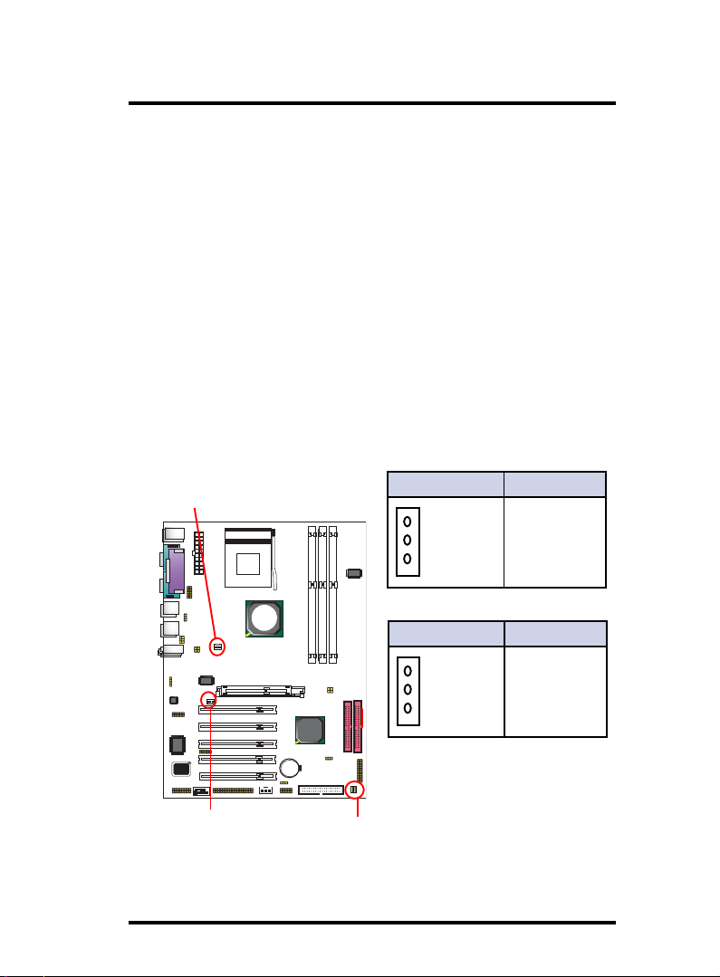
1.7.5 Fan Connectors: FAN1/CPUFAN/SYSFAN
CPUFAN1
Connector
RTL
W83697
BIOS
FAN1
Connector
CPU/SYSFAN Pin Definition
1 Sensor
1
2
2 +12VDC
3
3 Ground
KT400A
VIA
Socket 462
FAN1 Pin Definition
1 Ground
8100BL
VIA
VT8235
SYSFAN1
Connector
1-15
1
2
2 +12VDC
3
3 Ground
Page 16
Chapter 1 Motherboard 7KT400A
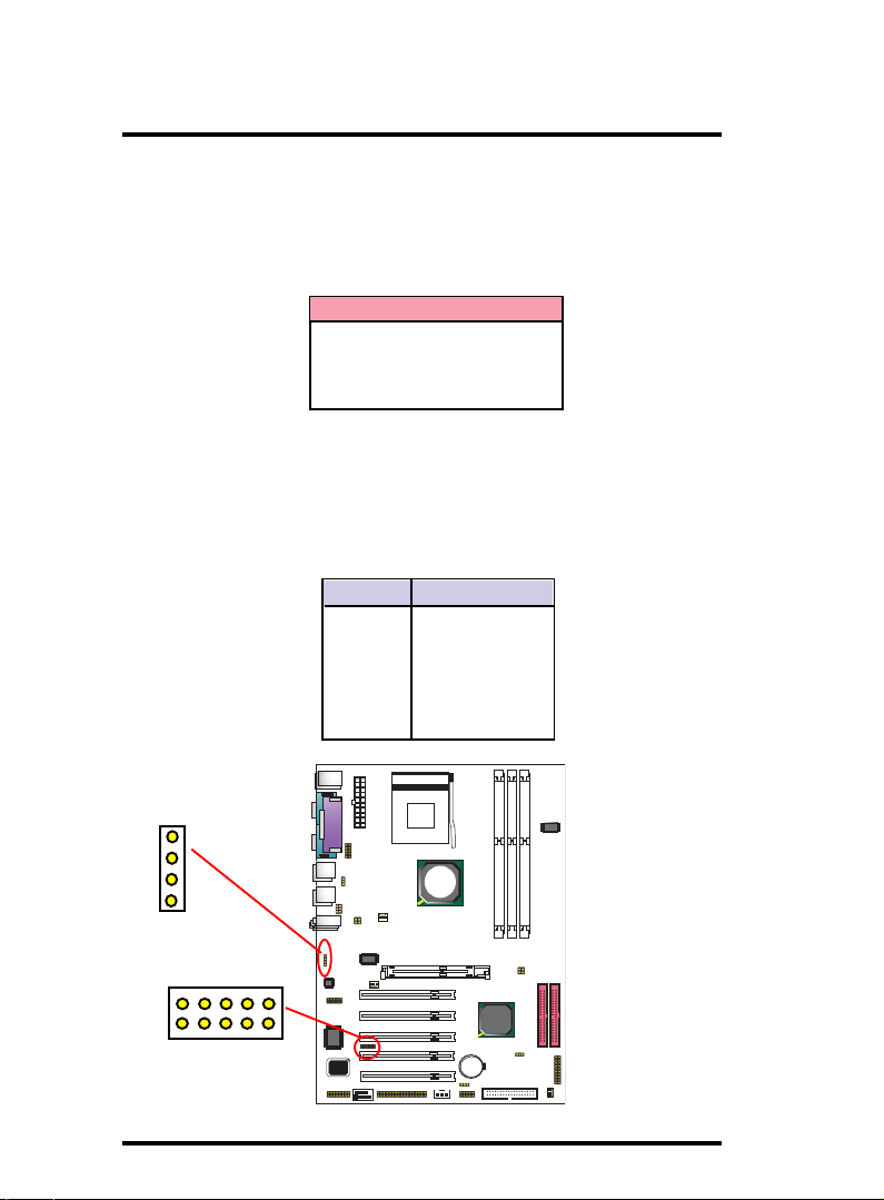
1.7.6 CD Audio-In Connectors: CDIN1
CDIN1 and CDIN2 are the connectors for CD-Audio Input signal.
Please connect them to CD-ROM CD-Audio output connector.
CDIN1 and CDIN2 have the same pin assignment but different
pin pitch.
Pin CDIN1 Definition
1 CD-L
2 GND
3 GND
4 CD-R
1.7.7 IR infrared module: IR/CIR Connector
This connector supports the optional wireless transmission
and reception infrared module. You must configure the setting
through the BIOS setup to use the IR function.
IR1 Pin Assignment
1 +5V
2 N/A
3 IRRX
4 GND
5 IRTX
CDIN1
CIR
IR
4
1
1 2 3 4 5
1 2 3 4 5
Socket 462
VIA
KT400A
8100BL
RTL
VIA
W83697
BIOS
VT8235
1-16
Page 17
Chapter 1 Motherboard 7KT400A
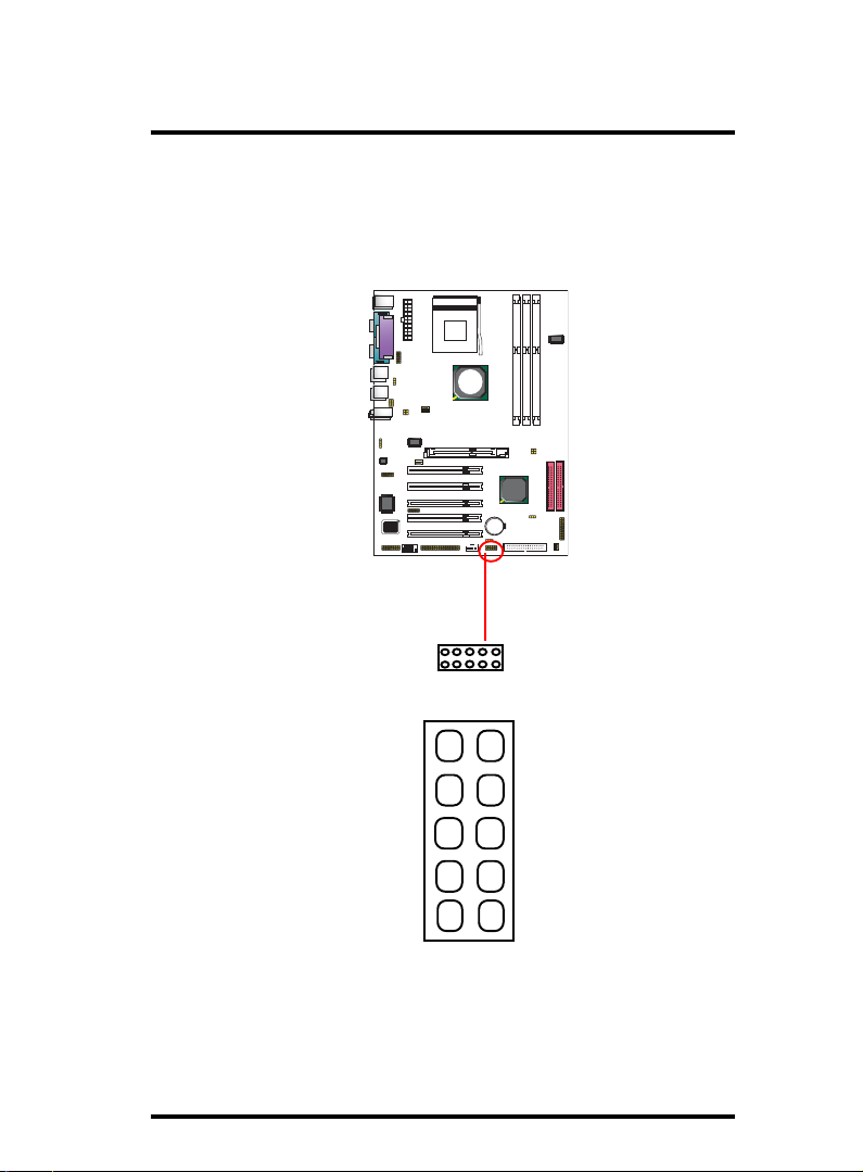
1.7.8 USB Pin Header: USB4/5
USB4/5 is 2x5 Pin Headers for support of external USB ports.
Each USB pin header requires a USB cable for expansion of two
USB ports. This optional USB cable is available from your
motherboard dealer or vendor.
Socket 462
VIA
KT400A
8100BL
RTL
VIA
W83697
BIOS
VT8235
5VUSB
USBDT4-
USBDT4+
GND
GND
2
1
USB4/5
2
1
910
1-17
10
9
GND
GND
USBDT5+
USBDT5-
5VUSB
Page 18
Chapter 1 Motherboard 7KT400A
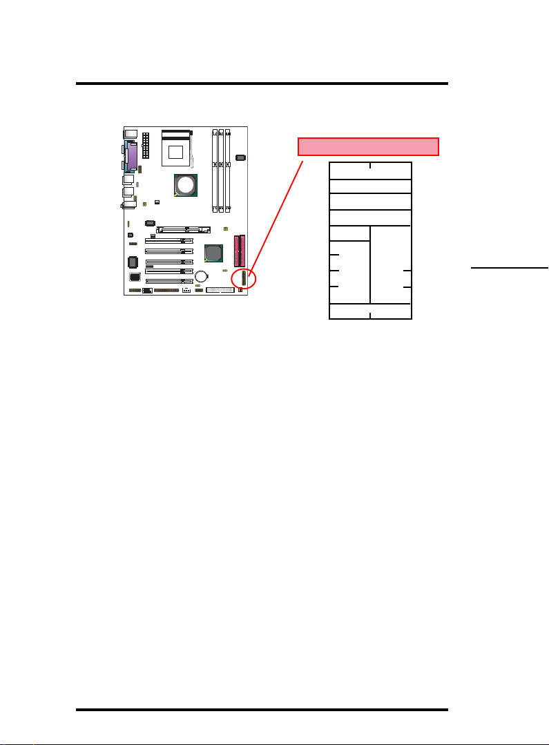
1.7.9 Front Panel Connectors: PANEL1
Socket 462
Front Panel Connectors
(+)
20
VIA
KT400A
8100BL
RTL
VIA
W83697
BIOS
VT8235
SMI LED
18
16
14
12
(+)
HD LED
(Void)
RST
EXTSMI
10
8
6
SPEAKER
(+) (+)
4
PS SW
2
PSSW
The system power is controlled by a momentary switch
connected to this lead. Pushing the button once will switch
the system ON.
Power LED Lead (PW_LED)
The system power LED lights when the system power is on.
(-)
19
17
15
13
11
9
7
5
3
PW LED/Keylock
(+)
1
(Void)
Speaker Connector (SPEAKER)
The speaker (onboard or offboard) provides error beep code
information during the Power Self-Test when the computer
cannot use the video interface. The speaker is not connected
to the audio subsystem and does not receive output from the
audio subsystem.
Hard Drive LED Connector (HD_LED)
This connector supplies power to the cabinet IDE activity LED.
Read and write activity by devices connected to the Primary or
Secondary IDE connectors will cause the LED to light up.
1-18
Page 19

Chapter 1 Motherboard 7KT400A
SMI Suspend Switch Lead
This allows the user to manually place the system into the
Suspend Green mode . System activity will be instantly
decreased to save electricity and expand the life of certain
components when the system is not in use. This 2-pin connector
(see the figure) connects to the case-mounted suspend switch.
If you do not have a switch for the connector, you may use the
"Turbo Switch” instead since it does not have a function. If
you want to use this connector, the "Suspend Switch" in the
Power Management Setup of the BIOS SOFTWARE section
should be enabled.
Reset Switch Lead (RST)
The connector can be connected to a reset switch. Press this
reset switch to restart system.
1-19
Page 20
Chapter 1 Motherboard 7KT400A
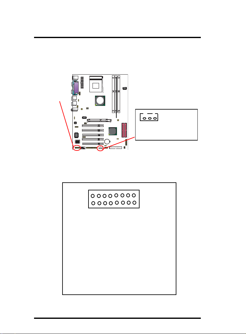
1.7.10 Wake On LAN Connector: WOL
WOL connector is designed to connect to connect to PCI LAN
card for waking up system by Ring signal sent in .
Socket 462
VIA
KT400A
WOL
Pin 1 5VSB
Pin 2 GND
Pin 3 Ring
8100BL
RTL
VIA
W83697
BIOS
VT8235
1
1.7.11 Game/MIDI Connector: J1
J1 connector is designed to support a Gsae Port or MIDI Port .
J1: Game/MIDI Connector
2
1
PIN1 Vcc PIN2 Vcc
PIN3 JOYABTNO PIN4 JOYBBTNO
PIN5 JOYAX_C PIN6 JOYBX_C
PIN7 GNDB PIN8 MDTX_C
PIN9 GNDB PIN10 JOYBY_C
PIN11 JOYAY_C PIN12 JOYBBTN1
PIN13 JOYABTN1 PIN14 MDRX_C
PIN15 VCC PIN16 N/A
16
15
1-20
Page 21
Chapter 1 Motherboard 7KT400A
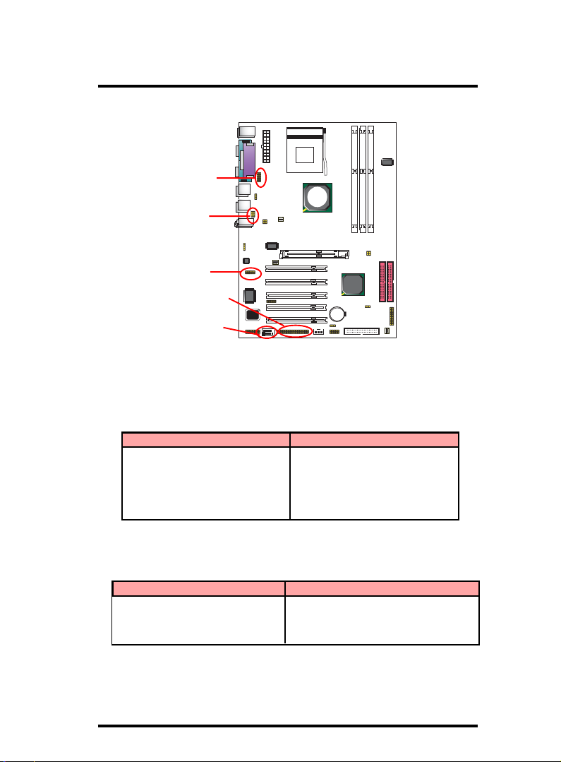
1.7.12 Smart Panel Connectors (optional):
Socket 462
SP-J6
VIA
KT400A
JP1
8100BL
RTL
J6
SP-J2
COM2
W83697
BIOS
VT8235
VIA
The motherboard provides the pin leads COM2, JP1, SP-J6 and
SP-J2 for Smart Panel connection. If you want POST Error Code
or Smart Panel function, please refer to Smart Panel manual.
1.7.12.1 Front COM2 Header Connector: COM2
For Smart Panel Serial connector to M/B COM2.
COM2 Pin Assignment COM2 Pin Assignment
1 RIN12 2 RIN32
3 DOUT22 4 DOUT32
5 GND 6 RIN22
7 DOUT12 8 RIN42
9 -XR12
1.7.12.2 Audio/Mic Auto Connector: JP1
For Smart Panel connector to M/B JP1.
Pin Assignment Pin Assignment
1 FRONT_OUTL_L 2 FRONT_OUTL_R
3 MIC1_L 4 MIC2_R
5 LINE_IN_L 6 LINE_IN_R
1-21
Page 22

Chapter 1 Motherboard 7KT400A
1.7.12.3 SPII Printer Error LED Port: SP-J6
For Smart Panel connector ERR1 to M/B SP-J6.
Pin Assignment Pin Assignment
1 ERD4 2 ERD0
3 ERD5 4 ERD1
5 ERD6 6 ERD2
7 ERD7 8 ERD3
9 GND 1 0 NC
1.7.12.4 Second BIOS Connector: SP-J2
For Smart Panel connector SP-J2 to M/B SP-J2.
Pin Assignment Pin Assignment
1 XD0 2 +5 V
3 XD1 4 SA 0
5 XD2 6 SA 1
7 XD3 8 SA 2
9 XD4 10 SA 3
11 XD5 12 SA4
13 XD6 14 SA5
15 XD7 16 SA6
17 GND 18 DISABLE
19 -ROMCS 20 SA7
21 -MBMR 22 SA 8
23 -MBMW 24 SA 9
25 SA18 26 SA10
27 SA17 28 SA11
29 SA16 30 SA12
31 SA15 32 SA13
33 GND 34 SA14
1-22
Page 23
Chapter 1 Motherboard 7KT400A
1.7.12.5 6-channel SP-DIF Audio Connector: J6
J6 is designed to support the 6-channel SP-DIF Audio
Connector, and this is an optional funtion.
Pin Assignment Pin Assignment
1 AVDD5V 2 Center
3 NC 4 Lef-out
5 SPDIFI 6 GND-Aud
7 SPDIFO 8 Sur-out-L
9 GND 10 Sur-out-R
1-23
Page 24
Chapter 1 Motherboard 7KT400A
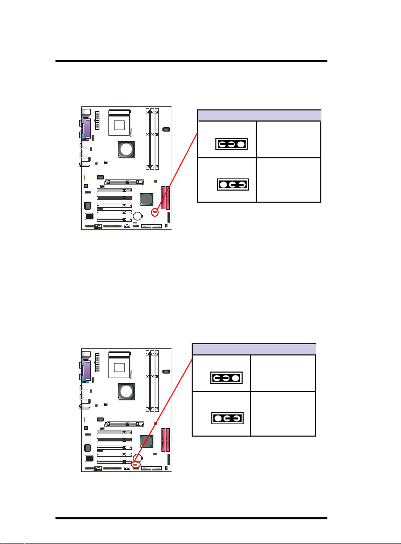
1.7.13 CMOS Function Selector: Clear_CMOS
When you have problem with booting system, you may clear
CMOS to restore the optimum default BIOS data.
KT400A
Socket 462
VIA
Jumper Clear CMOS
1-2 closed
1
Normal
(Default)
8100BL
RTL
VIA
W83697
BIOS
VT8235
2-3 closed
1
Clear CMOS
1. Remove the Jumper cap of JP3 from 1-2.
2. After 1 or two seconds, set JP3 to 2-3 closed with the jumper
cap.
3. After 1 or two seconds, restore the JP3 to 1-2 closed.
Now, the CMOS RAM has restored to the optimum default
setting.
1.7.14 USB4/5 Wake-up Selector: J4
JP4 is designed to select the USB1 wake up function of system
from ACPI S3 Suspend Mode.
Socket 462
VIA
KT400A
8100BL
RTL
VIA
W83697
BIOS
VT8235
J4: USB4/5 Wake-up Select
1-2 closed
1
2-3 closed
1
Disabled
(Default)
Enabled
1-24
Page 25
Chapter 1 Motherboard 7KT400A
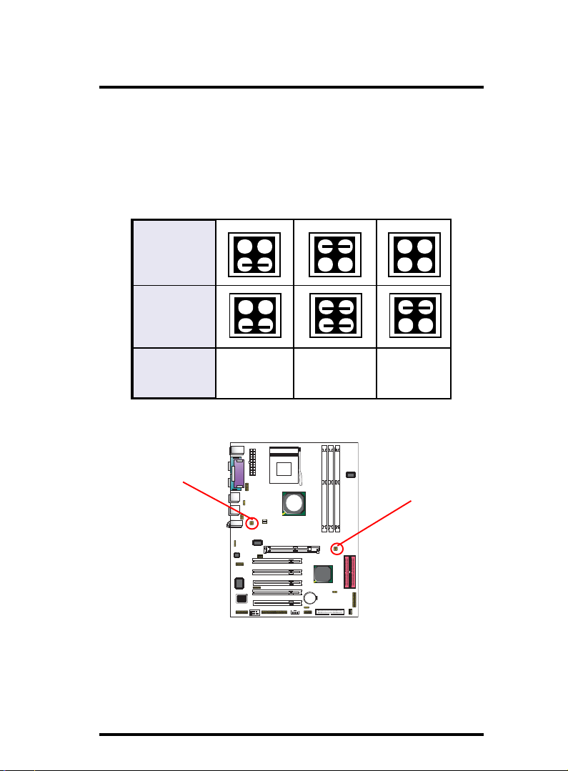
1.7.15 CPU Clock Frequency Selector: J3 & J5
J3 & J5 are designed to detect the CPU Frequency on board.
This motherboard support 100/133/166 MHz , while 133 MHz is
default CPU clock.
J3 Setting
J5 Setting
4
2
4
2
CPU(MHz) 166 MHz
J3
RTL
W83697
BIOS
3
4
1
2
3
4
1
2
100 MHz
Socket 462
VIA
KT400A
8100BL
VIA
VT8235
3
4
1
2
3
4
1
2
133 MHz
(default)
3
1
3
1
J5
1-25
Page 26
Chapter 1 Motherboard 7KT400A
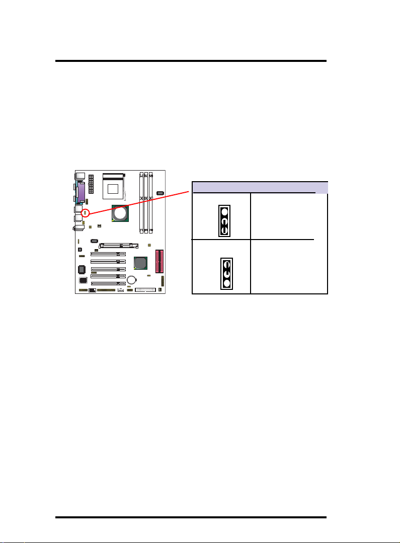
1.7.16 Ports USB0/1, 2/3 Wake-up Selector : J2
J2 is designed to select the USB1 wake up function of system
from ACPI S3 Suspend Mode.
Socket 462
J2: USB0/1,2/3 Wake-up Select
VIA
1-2 closed
KT400A
Disabled
(Default)
8100BL
RTL
1
2-3 closed
VIA
W83697
BIOS
VT8235
1
Enabled
1-26
Page 27

Chapter 2 7KT400A BIOS Setup
Chapter 2
BIOS Setup
2. BIOS Setup
2.1 BIOS Support
This chapter discusses the Award BIOS Setup program
built in the ROM BIOS. The Setup program allows the user
to modify the basic system configuration. The modification
is then stored in battery-backed RAM so that it can retain the
setup information after the power is turned off. The Award
BIOS installed in your computer system ROM (Read Only
Memory)is a custom version of an industry standard BIOS.
The BIOS provides critical low-level support for standard devices such as disk drives and serial and parallel ports. This
chapter is intended for guiding you through the process of
configuring your system BIOS.
Plug and Play Support
This AWARD BIOS supports the Plug and Play Version 1.0A
specification. ESCD(Extended System Configuration Data)
write is also supported.
EPA Green PC Support
This AWARD BIOS supports Version 1.03 of the EPA Green
PC specification.
PCI Bus Support
This AWARD BIOS also supports Version 2.1 of the Intel
PCI (Peripheral Component Interconnect)local bus
specification.
2-27
Page 28

Chapter 2 7KT400A BIOS Setup
APM Support
This AWARD BIOS supports Version 1.1&1.2 of the
Advanced Power Management(APM) specification.Power
management features are implemented via the System
Management Interrupt(SMI). Sleep and Suspend power
management modes are supported. Power to the hard disk
drives and video monitors can be managed by this AWARD
BIOS.
DRAM Support
DDR (Double Data Rate) are supported.
Setup Menu
In general, you use the arrow keys to highlight items of the
Main BIOS Setup Menu, press <Enter>to select, use the
<PgUp>and <PgDn>keys to change entries, press<F1>for
help and press <Esc> to quit The following table provides
more detail about how to navigate in the Setup program by
using the keyboard.
Note:
BIOS version 1.0 is for reference only. If there is a
change in BIOS version, please use the actual version
on the BIOS.
2-28
Page 29

Chapter 2 7KT400A BIOS Setup
Keystroke Function
Up arrow Move to previous item
Down arrow Move to next item
Left arrow Move to the item on the left(menu bar)
Right arrow Move to the item on the right(menu bar)
Esc Main Menu: Quit without saving changes
Submenus: Exit Current page to the next higher
level menu
Move Enter Move to item you desired
PgUp key Increase the numeric value or make changes
PgDn key Decrease the numeric value or make changes
+Key Increase the numeric value or make changes
-Key Decrease the numeric value or make changes
Esc Key Main menu-Quit and not save changes into
CMOS
Status Page Setup Menu and option Page Setup
Menu-Exit Current page and return to Main
Menu
F1 Key General help on Setup navigation keys.
F5 Key Load previous values from CMOS
F6 Key Load the fail-safe defaults from BIOS default
table
F7 Key Load the optimized defaults
F10 Key Save all the CMOS changes and exit
2-29
Page 30
Chapter 2 7KT400A BIOS Setup
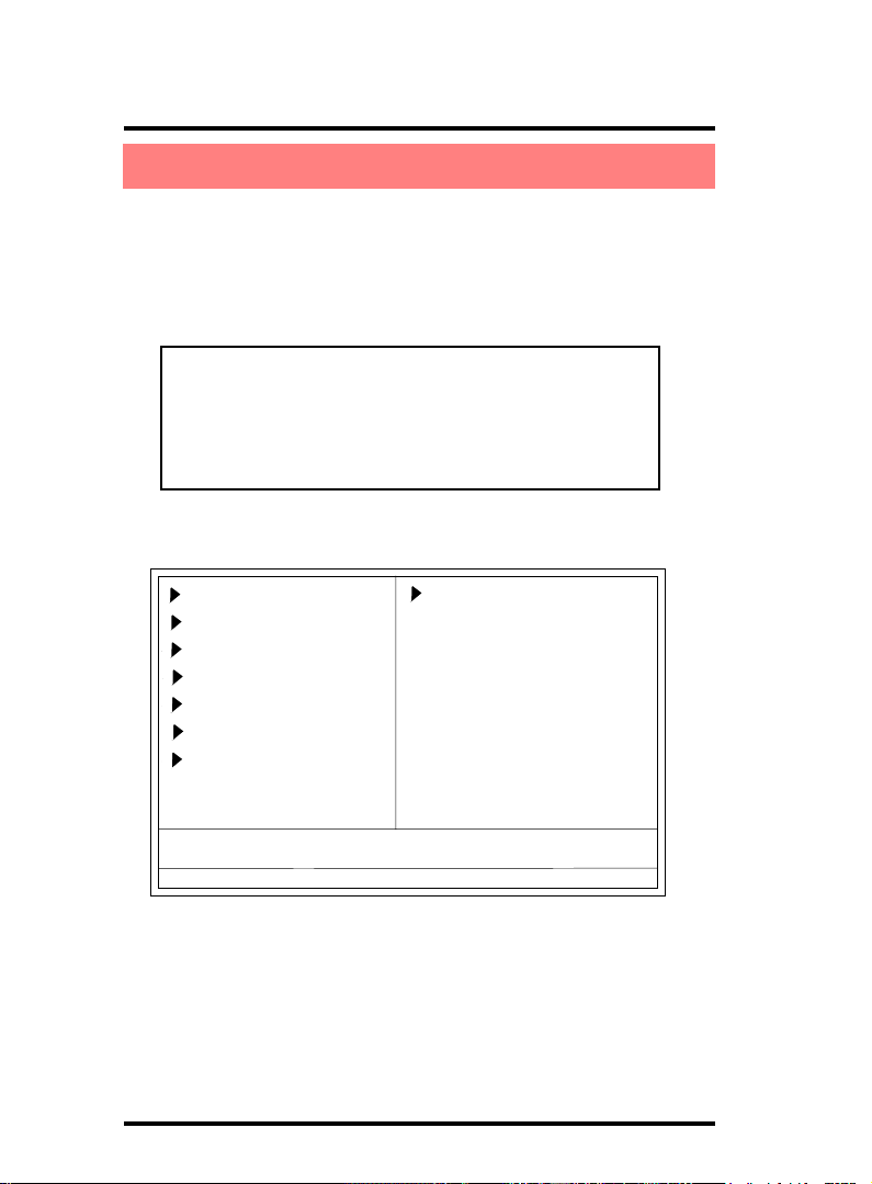
2.2 Main Menu
Once you enter AWARD BIOS CMOS Set up Utility, the
Main Menu will appear on the screen and allows you to select from several setup function. Use the arrow keys to select the items and press<Enter> to enter the sub-menu.
Attention:
The information about BIOS defaults in this manual
is just for reference, please refer to the BIOS installed
on board for default BIOS confirmation.
Phoenix - AwardBIOS CMOS Setup Utility
Standard CMOS Features
Advanced BIOS Features
Advanced Chipset Features
Integrated Peripherals
Power Management Setup
PNP/PCI Configurations
PC Health Status
Esc : Quit F9: Menu in BIOS ←→↑↓: Select Item
F10 : Save & Exit Setup
Time , Date , Hard Disk Type ...
Frequency/Voltage Control
Load Fail-safe Defaults
Load Optimized Defaults
Set Supervisor Password
Set User Password
Save & Exit Setup
Exit without Saving
2-30
Page 31

Chapter 2 7KT400A BIOS Setup
Standard CMOS Features
This setup page includes all the items in standard compatible
BIOS.
Advanced BIOS Features
This setup page includes all the items of the BIOS special
enchanced features.
Advanced Chipset Features
This setup page includes all the items of the Chipset special
enchanced features.
Integrated Peripherals
This selection page includes all the items of the IDE hard
drive and Programmed Input/Output features.
Power Management Setup
This setup page includes all the items of the power manage
ment features.
PnP/PCI Configurations
This setup page includes the user defined or default IRQ
Setting.
PC Health Status
This page shows the hardware Monitor information of the
system.
Frequency/Voltage Control
This setup page controls the CPU's clock and frequency
ratio.
Load Fail-safe Defaults
Use this menu to load the BIOS default values for the
minimal/stable performance for your system to operate.
2-31
Page 32

Chapter 2 7KT400A BIOS Setup
Load Optimized Defaults
These settings are for configuring a workable computer
when something is wrong. If you cannot boot the computer
successfully, select the BIOS Setup options and try to
diagnose the problem after the computer boots. These
settings do not provide optional performance.
Set Supervisor/User Password
Change, set, or, disable password. It allows you to limit access
to the system and Setup, or just to Setup.
Save & Exit Setup
Save CMOS value changes to CMOS and exit setup.
Exit Without Saving
Abandon all CMOS value changes and exit setup.
2-32
Page 33

Chapter 2 7KT400A BIOS Setup
2.3 Standard CMOS Features
This main option in the Standard CMOS Setup Menu is
divided into 10 fields or items. Each field provides one or
more setup choices. Use the arrow keys to highlight the field
and then use the <PgUp> or <PgDn> keys to select the value
or choice.
Phoenix - AwardBIOS CMOS Setup Utility
Standard CMOS Features
Date(mm:dd:yy) Tue,Jun 6 2002 Item Help
Time (hh:mm:ss) 11:26:10
IDE Primary Master None
IDE Primary Slave Change the day,
IDE Secondary Master month,year
IDE Secondary Master None and century.
Drive A 1.44M,3.5 in
Drive B None
Floppy 3 Mode Support Disabled
Video EGA/VGA
Halt On All,But Keyboard
Base Memory 640K
Extended Memory 65472K
Total Memory 1024K
←→↑↓: Move Enter:Select +/-/PU/PD:Value F10:Save ESC:Exit F1:General Help
F5:Previous Values F6:Fail-Safe Defaults F7:Optimized Defaults
Menu Level
2-33
Page 34

Chapter 2 7KT400A BIOS Setup
Main Menu Selections
This table shows the selections that you can make on the
Main Menu.
Item Options Description
Date Month Day Year Set the system,date. Note that the
(mm : dd :yy)
Time
(hh : mm : SS)
IDE Primary Options are in its sub Press<Enter> to enter sub menu.
Master menu.
IDE Primary/ Options are in its sub Press<Enter> to enter sub menu.
Slave menu.
IDE Second- Options are in its sub Press<Enter> to enter sub menu.
ary Master menu.
IDE Second- Options are in its sub Press<Enter> to enter sub menu
ary Slave menu.
Drive A None Select the type of floppy disk
Drive B 360K,5.25in, drive installed in your system.
720K,3.5M
Floppy
3 Mode
Support
Hour Minute Second Select the hour, minute and
1.2M,5.25in
1.44M,3.5in
2.88M,3.5in
Disabled Disable or support the 3rd
Driver A
‘Day’ automatically changes
when you set the data.
second of the time.
floppy mode in Drive A
Video EGA/VGA Select the default video device.
CGA 40
CGA 80
MONO
2-34
Page 35
Chapter 2 7KT400A BIOS Setup
Item Options Description
Halt On All Errors Select the situation in which you
No Errors want the BIOS to stop the POST
All, but Keyboard process and notify.
All, but Diskette
All, but Disk/Key
Base Memory (640K) The amount of conventional mem-
ory detected during boot up.
Extended ( 65472K ) The amount of conventional mem-
Memory ory detected during boot up.
Total ( 1024K ) The total memory available in
Memory system.
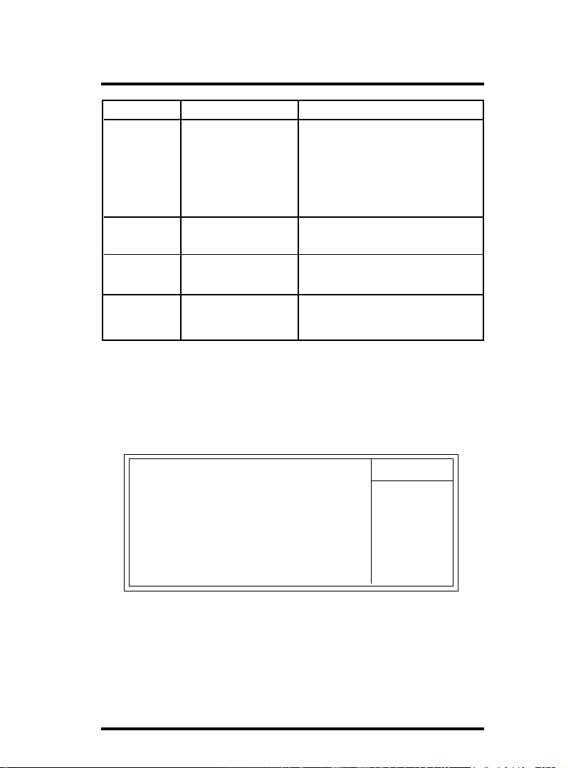
IDE Primary(Master/Slave)/Secondary(Master/Slave)
Press Enter on these items to show the following sub-menu:
Primary Master/Secondary
IDE HDD Auto-Detection Press Enter Item Help
IDE Primary Master Auto
Access Mode Auto Menu Level
Capacity 13022MB
Cylinder 25232
Head 16
Precomp 0
Landing Zone 25231
Sector 61
←→↑↓: Move Enter:Select +/-/PU/PD:Value F10:Save ESC:Exit F1:General Help
F5:Previous Values F6:Fail-Safe Defaults F7:Optimized Defaults
2-35
Page 36

Chapter 2 7KT400A BIOS Setup
IDE HDD Auto-Detection
Press Enter on this item to let BIOS auto-detect your Hard Disk
and show all the Primary Hard Disk Parameters ( Capacity,
Cylinder, Head, Precomp, Landing Zone, Sector) on the menu.
IDE Primary(Master/Slave) / Secondary(Master/Slave)
This item allows you to detect the Hard Disk in 3 ways.
The Choices: Auto: BIOS Auto-detect HDD;
None: No Hard Disk detected;
Manual: Manually detect HDD
Access Mode
This item allows you to select the Access mode to the Hard
Disk..
The Choices:
CHS: Select the Cylinder, Head, Sector addressing mode to
access Hard Disk;
LBA: Select the Logical Block Addressing mode to access Hard
Disk.
Large: Select Large Mode to access Hard Disk;
Auto: Allow BIOS to auto-access Hard Disk;
Capacity
Showing the capacity of Hard Disk in MB.
Cylinder
Showing the number of cylinder in the Hard Disk.
Head
Showing the number of heads in the Hard Disk.
Precomp
The number of Pre-compensation.
Landing Zone
Number of Landing zone in the Hard Disk.
Sector
The number of Sector in the Hard Disk.
2-36
Page 37

Chapter 2 7KT400A BIOS Setup
2.4 Advanced BIOS Features
Phoenix - AwardBIOS CMOS Setup Utility
Advanced BIOS Features
Virus Warning Disabled
CPU Internal Cache Enabled
External Cache Enabled
CPU L2 Cache ECC Checking Enabled
Quick Power On Self Test Enabled
First Boot Device Floopy
Second Boot Device HDD-0
Third Boot Device CD-ROM
Boot Other Device Enabled
Swap Floppy Drive Disabled
Boot Up Floppy Seek Disabled
Boot Up NumLock Status On
Gate A20 Option Fast
Typematic Rate Setting Disabled
X Typematic Rate (Chars/Sec) 6
X Typematic Delay (Msec) 25 0
Security Option Setup
OS Select For DRAM >64MB Non-OS2
HDD S.M.A.R.T. Capability Disabled
Video BIOS Shadow Enabled
EPA / (H/W Monitor) Show H/W Monitor
←→↑↓: Move Enter:Select +/-/PU/PD:Value F10:Save ESC:Exit F1:General Help
F5:Previous Values F6:Fail-Safe Defaults F7:Optimized Defaults
Item Help
Virus Warning
This option allows you to choose the VIRUS Warning feature
for IDE Hard Disk boot sector protection. If this function is
enabled and someone attempts to write data into this area, BIOS
will show a warning message on screen and alarm beep.
The Choices:
Disabled(default), Enabled.
2-37
Page 38

Chapter 2 7KT400A BIOS Setup
CPU Internal / External Cache
Allows you to Enable or Disable the CPU’s L1(Internal) / L2
(External) cache to provide better performance.
The choices:
Enabled(default); Disabled
CPU L2 Cache ECC Checking
Allows you to Enable or Disable the CPU L2 cache ECC Checking
function.
The choices:
Enabled; Disabled
Quick Power On Self Test
This category speeds up Power on self-Test(POST) after you
power up the computer. If it is set to Enabled, BIOS will shorten
or skip some check items during POST.
The choices:
Enabled(default); Disabled
First/Secondary/Third Boot Device
This BIOS attempts to load the operating system from the devices
in the sequence selected in these items.
The Choices:
Floppy, LS120, HDD-0, SCSI, CDROM, HDD-1, HDD-2, HDD-3,
ZIP100, LAN, USB-FDD, USB-Zip, USB-CDROM, USB-HDD,
Disabled.
Boot Other Device
Allows user to set booting from other devices.
The Choices:
Enabled(default), Disabled.
Swap Floppy Drive
If the system has two floppy drives, you can swap the logical
drive name assignments.
The Choices:
Disabled(default), Enabled.
2-38
Page 39

Chapter 2 7KT400A BIOS Setup
Boot Up Floppy Seek
If enabled, this item allows BIOS to test floppy drives to
determine whether they have 40 or 80 tracks.
The Choices:
Disabled(default), Enabled.
Boot Up NumLock Status
Select power on state for Numlock..
The Choices
On (default): Numpad is number keys;
Off: Numpad is arrow keys;
Gate A20 Option
Select if chipset or keyboard controller should control Gate
A20.
The choices:
Normal: A pin in the keyboard controller controls Gate A20.
Fast (default): Lets chipset control Gate A20.
Typematic Rate Setting
Allows user to adjust the key stroke repeat rate.
The choices:
Enabled: Enabled this option to adjust the keystroke repeat
rate; Disabled (default): Enabled.
Typematic Rate (Char/Sec)
Range between 6(default) and 30 characters per second. This
option controls the speed of repeating keystrokes.
Typematic Delay (Msec)
This option sets the time interval for displaying the first and the
second characters.
The Choices: 250(default), 500, 750, 1000.
2-39
Page 40

Chapter 2 7KT400A BIOS Setup
Security Option
This category allows you to determine whether to use password
access the system and Setup,or just Setup.
The choices:
System: To access system and BIOS Setup with correct
password.
Setup (default): To access BIOS Setup with correct password.
OS Select For DRAM >64MB
Select the operating system that is running with greater than
64MB of RAM on the system.
The Choices: Non-OS2(default), OS2.
HDD S.M.A.R.T. Capability
Allows user to choose the Self-monitoring Analysis and
Reporting Technology for Hard Disk Drive.
The choices: Disabled(default); Enabled
Video BIOS Shadow
Use this item to enable/disable the Video BIOS Shadow function.
The Choices: Enabled; Disabled
EPA / (H/W Monitor) Show
Use this item to enable/disable the Environmental Protection
Association (EPA) / Hardware Monitor) logo on initiating screen..
The choices: H/W Monitor; EPA Logo
2-40
Page 41

Chapter 2 7KT400A BIOS Setup
2.5 Advanced Chipset Features
This section allows you to configure the system based
features of the installed chipset. This chipset manages bus
speeds and access to system memory resources, such as
DRAM and external cache. It also coordinates communications of the PCI bus. It must be stated that these items should
never be altered. The default settings are set up to provide
the best operating conditions for your system. The time you
might need to make any changes would be if you discover
that data is lost while using your system.
Phoenix - AwardBIOS CMOS Setup Utility
Advanced Chipset Features
DRAM Clock/Drive Control Press Enter
AGP & P2P Bridge Control Press Enter
CPU & PCI Bus Control Press Enter
Memory Hole Disabled
System BIOS Cacheable Disabled
Video RAM Cacheabled Disabled
←→↑↓: Move Enter:Select +/-/PU/PD:Value F10:Save ESC:Exit F1:General Help
F5:Previous Values F6:Fail-Safe Defaults F7:Optimized Defaults
2-41
Item Help
Page 42

Chapter 2 7KT400A BIOS Setup
DRAM Clock/Drive Control
Press Enter on this item to open the Sub-menu as shown below:
Phoenix - AwardBIOS CMOS Setup Utility
DRAM Clock/Drive Control
Current FSB Frequency 100MHz
Current DRAM Frequency 100MHz
DRAM Clock By SPD
DRAM Timing Auto By SPD
x DRAM CAS Latency 2.5
x Bank Interleave Disabled
x Precharge to Active(Trp) 3T
x Tras Non-DDR400/DDR400 7T
x Active to CMD(Trcd) 3T
DRAM Burst Length 4
DRAM Command Rate 2T Command
Write Recovery Time 3T
←→↑↓: Move Enter:Select +/-/PU/PD:Value F10:Save ESC:Exit F1:General Help
F5:Previous Values F6:Fail-Safe Defaults F7:Optimized Defaults
Item Help
Current FSB Frequency
This item shows the current FSB Frequency
Current DRAM Frequency
This item shows the current DRAM Frequency
DRAM Clock
This item is to set the DRAM clock..
The Choices: By SPD; 100 MHz; 133 MHz; 166 MHz; 200 MHz
DRAM Timing
This item is to set the DRAM transaction timing.
The Choices: Auto by SPD; Turbo; Ultra; Manual
2-42
Page 43

Chapter 2 7KT400A BIOS Setup
x DRAM CAS Latency
When DRAM Timing is set Manual, use this item to set the
DRAM CAS Latency tine. .
The Choices: 1.5; 2; 2.5; 3
x Bank Interleave
When DRAM Timing is set Manual, use this item to set the
DRAM Bank Interleave.
The Choices: Disabled; 2 Bank; 4 Bank
x Precharge to Active(Trp)
When DRAM Timing is set Manual, use this item to set the
DRAM Precharge to Active(Trp) cycle.
The Choices: 2T; 3T
x Tras Non-DDR400/DDR400
When DRAM Timing is set Manual, use this item to set the Tras
Non-DDR400/DDR400 cycle.
The Choices: 7T; 10T
x Active to CMD(Trcd)
When DRAM Timing is set Manual, use this item to set the
DRAM Active to CMD(Trcd) cycle.
The Choices: 3T; 2T
DRAM Burst Length
Use this item to set the DRAM Burst cycle Length.
The Choices: 4; 8
DRAM Command Rate
Use this item to set the DRAM Command Rate.
The Choices: 2T Command; 1T command
Write Recovery Time
Use this item to set the Write Recovery Time.
The Choices: 3T; 2T
2-43
Page 44

Chapter 2 7KT400A BIOS Setup
AGP P2P Bridge Control
Press Enter on this item to open the Sub-menu as shown below:
Phoenix - AwardBIOS CMOS Setup Utility
AGP P2P Bridge Control
AGP Aperture Size 128M
AGP Mode 4X
AGP Driving Control Auto
x AGP Driving Value DA
AGP Fast Write Enabled
AGP Master 1 WS Write Disabled
AGP Master 1 WS Read Disabled
AGP 3.0 Calibration Cycle Enabled
←→↑↓: Move Enter:Select +/-/PU/PD:Value F10:Save ESC:Exit F1:General Help
F5:Previous Values F6:Fail-Safe Defaults F7:Optimized Defaults
Item Help
AGP Aperture Size
This item is to set the AGP Aperture memory size.
The Choices: 256M; 128M; 64M; 32M; 16M; 8M; 4M
AGP Mode
This item is to set the AGP mode.
The Choices: 8X; 4X; 2X; 1X
AGP Driving Control
This item is to set the AGP Driving Control mode.
The Choices: Auto; Manual
2-44
Page 45

Chapter 2 7KT400A BIOS Setup
x AGP Driving Time
When AGP Driving Control is set manual, use this item to set
the AGP Driving address value.
The Choices: 00 ~ FF in 1h stepping
AGP Fast Write
This item is to enable / disable the AGP Fast Write function.
The Choices: Enabled; Disabled
AGP Master 1 WS Write
This item is to enable / disable the AGP Master 1 WS Write
function.
The Choices: Enabled; Disabled
AGP Master 1 WS Read
This item is to enable / disable the AGP Master 1 WS Read
function.
The Choices: Enabled; Disabled
AGP 3.0 Calibration Cycle
This item is to enable / disable the AGP 3.0 Calibration Cycle
function.
The Choices: Enabled ; Disabled
2-45
Page 46

Chapter 2 7KT400A BIOS Setup
CPU & PCI Bus Control
Press Enter on this item to open the Sub-menu as shown below:
Phoenix - AwardBIOS CMOS Setup Utility
CPU & PCI Bus Control
PCI1 Master 0 WS Write Enabled
PCI2 Master 0 WS Write Enabled
PCI1 Post Write Enabled
PCI2 Post Write Enabled
VLink 8X Support Enabled
PCI Delay Transaction Enabled
←→↑↓: Move Enter:Select +/-/PU/PD:Value F10:Save ESC:Exit F1:General Help
F5:Previous Values F6:Fail-Safe Defaults F7:Optimized Defaults
Item Help
PCI1/2 Master 0 WS Write
This item is to enable / disable the PCI1/2 Master 0 Wait State
Write function.
The Choices: Enabled; Disabled
PCI1/2 Post Write
This item is to enable / disable the PCI1/2 POST Write function.
The Choices: Enabled; Disabled
VLink 8X Support
This item is to Enable / disable the VLink 8X Support.
The Choices: Enabled; Disabled
PCI Delay Transaction
This item is to Enable / disable the PCI Delay Transaction.
The Choices: Enabled; Disabled
2-46
Page 47

Chapter 2 7KT400A BIOS Setup
Memory Hole
Use this item to enable or disable the Memory Hole.
The Choices: Disabled; 15M ~ 16M
System BIOS Cacheable
Use this item to enable / disable the System BIOS Cacheable
function.
The choices: Enabled; Disabled
Video RAM Cacheabled
Use this item to enable / disable the Video BIOS Cacheable
function.
The choices: Enabled; Disabled
2-47
Page 48
Chapter 2 7KT400A BIOS Setup
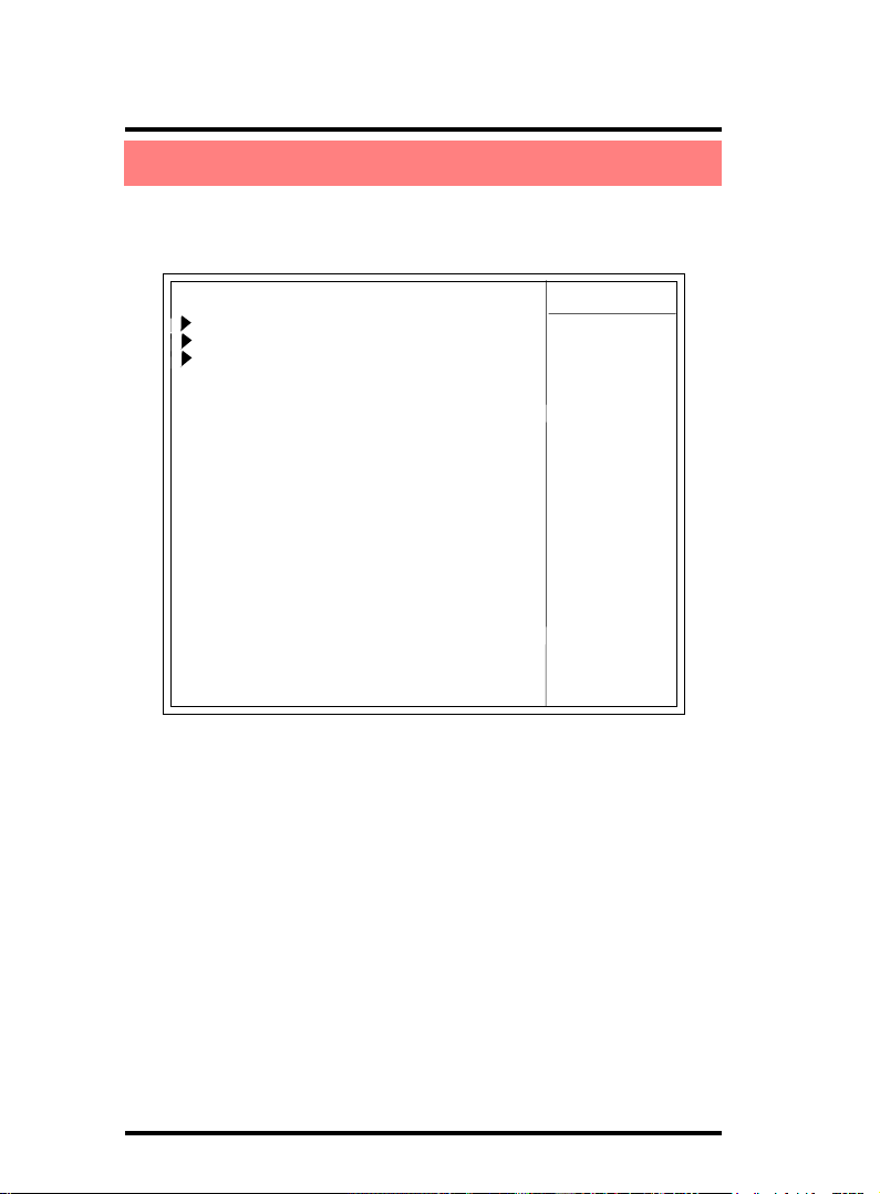
2.6 Integrated Peripherals
Phoenix - AwardBIOS CMOS Setup Utility
Integrated Peripherals
Item Help
VIA Onchip IDE Device Press Enter
VIA Onchip PCI Device Press Enter
Super IO Device Press Enter
Init Display First PCI Slot
IDE HDD Block Mode Enabled
←→↑↓: Move Enter:Select +/-/PU/PD:Value F10:Save ESC:Exit F1:General Help
F5:Previous Values F6:Fail-Safe Defaults F7:Optimized Defaults
2-48
Page 49

Chapter 2 7KT400A BIOS Setup
VIA OnChip IDE Device
Press Enter on this item to open the Sub-menu as shown below:
Phoenix - AwardBIOS CMOS Setup Utility
VIA OnChip IDE Device
OnChip IDE Channel0 Enabled
OnChip IDE Channel1 Enabled
IDE Prefetch Mode Enabled
Primary Master PIO Auto
Primary Slave PIO Auto
Secondary Master PIO Auto
Secondary Slave PIO Auto
Primary Master UDMA Auto
Primary Slave UDMA Auto
Secondary Master UDMA Auto
Secondary Slave UDMA Auto
←→↑↓: Move Enter:Select +/-/PU/PD:Value F10:Save ESC:Exit F1:General Help
F5:Previous Values F6:Fail-Safe Defaults F7:Optimized Defaults
Item Help
OnChip IDE Channel0
This item is to enable / disable the IDE Primary Master/Slave
channel.
The choices: Enabled; Disabled
OnChip IDE Channel1
This item is to enable / disable the IDE Secondary Master/Slave
channel.
The choices: Enabled; Disabled
IDE Prefetch Mode
This item is to enable / disable the IDE Prefetch Mode. If enabled,
data will be prefetched into buffer during data access.
The choices: Enabled; Disabled
2-49
Page 50

Chapter 2 7KT400A BIOS Setup
Primary Master/Slave PIO
If OnChip IDE Channel is enabled, this item is to select the IDE
Primary Master/Slave PIO mode (Programmed Input Output
Mode). Mode4 is the fastest mode.
The choices: Auto; Mode0; Mode1; Mode2; Mode3; Mode4
Secondary Master/Slave PIO
If OnChip IDE Channel1 is enabled, this item is to select the IDE
Secondary Master/Slave PIO mode (Programmed Input Output
Mode). Mode4 is the fastest mode.
The choices: Auto; Mode0; Mode1; Mode2; Mode3; Mode4
Primary Master/Slave UDMA
If OnChip IDE Channel0 is enabled, this item is to select the IDE
Primary Master/Slave UDMA mode (Ultra Direct Memory Access
Mode).
The choices: Auto; Disabled
Secondary Master/Slave UDMA
If OnChip IDE Channel0 is enabled, this item is to select the IDE
Secondary Master/Slave UDMA mode (Ultra Direct Memory
Access Mode).
The choices: Auto; Disabled
2-50
Page 51

Chapter 2 7KT400A BIOS Setup
VIA OnChip PCI Device
Press Enter on this item to open the Sub-menu as shown below:
Phoenix - AwardBIOS CMOS Setup Utility
VIA OnChip PCI Device
USB 2.0 Support Enabled
VIA-3058 AC97 Audio Auto
VIA-3068 MC97 Modem Auto
Onchip USB Controller All Disabled
USB Keyboard Support Enabled
←→↑↓: Move Enter:Select +/-/PU/PD:Value F10:Save ESC:Exit F1:General Help
F5:Previous Values F6:Fail-Safe Defaults F7:Optimized Defaults
Item Help
USB 2.0 Support
This item is to enable/disable the USB 2.0 device support..
The choices: Enabled; Disabled
VIA-3058 AC97 Audio
This item is to autodetect or disable the VIA AC’97 Audio.
The choices: Auto; Disabled
VIA-3068 MC97 Modem
This item is to autodetect or disable the VIA MC’97 Modem.
The choices: Auto; Disabled
Onchip USB Controller
This item is to select the USB ports supported by Onchip USB
Controller..
The choices: All Enabled; All Disabled;
1&2 USB Ports; 1&3 USB Ports;
1 USB Port
USB Keyboard Support
This item is to enable/disable the USB Keyboard function..
The choices: Enabled; Disabled
2-51
Page 52

Chapter 2 7KT400A BIOS Setup
Super IO Device
Press Enter on this item to open the Sub-menu as shown below:
Phoenix - AwardBIOS CMOS Setup Utility
VIA OnChip IDE Device
Onboard FDC Controller Enabled
Onboard Serial Port 1 3F8/IRQ4
Onboard Serial Port 2 2F8/IRQ3
UART Mode Select Normal
RxD, TxD Active Hi, Lo
IR Transmission Delay Enabled
UR2 Duplex Mode Half
Use IR Pins IR-Rx2Tx2
Onboard Parallel Port 378/IRQ7
Parallel Port Mode EC P
EPP Mode Select EPP1.7
ECP Mode Use DMA 3
Game Port Address 201
MIDI Port Address 3 30
MIDI Port IRQ 1 0
←→↑↓: Move Enter:Select +/-/PU/PD:Value F10:Save ESC:Exit F1:General Help
F5:Previous Values F6:Fail-Safe Defaults F7:Optimized Defaults
Item Help
Onboard FDC Controller
The choices: Enabled; Disbled
Onboard Serial Port 1/2
Select an address and corresponding interrupt for the first and
second serial ports.
The Choices: Auto; 3F8/IRQ4; 2F8/IRQ3; 3E8/IRQ4;2E8/
IRQ3; Disabled.
2-52
Page 53

Chapter 2 7KT400A BIOS Setup
UART Mode Select
This item allows you to select which Infra Red(IR) function of
the onboard I/O chip you wish to use.
The Choices: Normal(default), IrDA, ASKIR.
RxD’ TxD Active
This item allows you to select the high /Low status of the RxD,
TxD Active mode.
The Choices: Hi,Lo; Lo,Hi; Lo,Lo; Hi,Hi
IR Transmission delay
This item allows you to enable / disable the IR Transmission
Delay function.
The Choices: Enabled; Disabled
UR2 Duplex Mode
This item allows you to select which Infra Red(IR) function of
the onboard I/O chip you wish to use.
The Choices: Half (default), Full.
Use IR Pins
This item allows you to select the IR Pins.
The Choices: IR-Rx2Tx2; RxD2, TxD2
Onboard Parallel Port
This item allows you to select the Onboard Parallel Port .
The Choices: 378/IRQ7; 278/IRQ5; 3BC/IRQ7; Disabled
Parallel Port Mode
The choices are for Parallel Port Mode select:
SPP: Using Parallel port as Standard Parallel Port;
EPP: Using Parallel port as Enhanced Parallel Port;
ECP: Using Parallel port as ExtendedCapabilites Port;
ECP+EPP Using Parallel port as ECP+EPP mode;
Normal;
2-53
Page 54

Chapter 2 7KT400A BIOS Setup
EPP Mode Select
The Choices: EPP1.7; EPP1.9
ECP Mode Use DMA
The Choices: 3, 1.
Game Port Address
The choices are for setting Game Port Address:
201 (default); 209; Disabled
MIDI Port Address
The choices are for setting MIDI Port Address:
290:300; 330 (default); Disabled.
MIDI Port IRQ
The choices are for setting MIDI Port IRQ:
10 (default): 5
Init Display First
Use this item to select the initial Display as the first display.
The choices: PCI Slot; AGP
IDE HDD Block Mode
Use this item to enable / disable the IDE HDD Block Mode (Multisector Mode).
The choices: Disabled; Enabled
2-54
Page 55
Chapter 2 7KT400A BIOS Setup
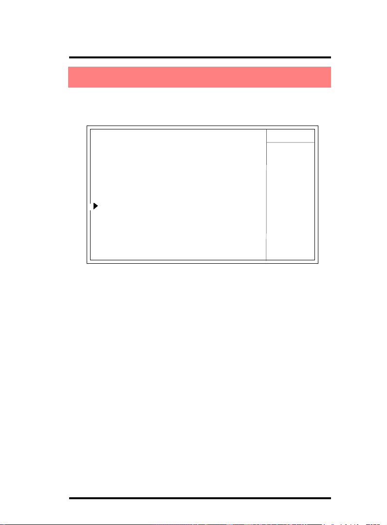
2.7 Power Management Setup
Phoenix - AwardBIOS CMOS Setup Utility
Power Management Setup
ACPI Function Enabled
ACPI Suspend Type S1(POS)
Power Management Option User Define
HDD Power Down Disabled
Suspend Mode Disabled
Video Off Option Suspend -> Off
Video Off Method V/H SYNC+Blank
Modem Use IRQ 3
Soft-off by PWR-BTTN Instant-off
IRQ/Event Activity Detect Press Enter
←→↑↓: Move Enter:Select +/-/PU/PD:Value F10:Save ESC:Exit F1:General Help
F5:Previous Values F6:Fail-Safe Defaults F7:Optimized Defaults
Item Help
ACPI Function
The choices are for enabling or disabling the Advanced
Configuration and Power Management (ACPI).
ACPI Suspend Type
The choices are for setting the suspend type under ACPI
operating system.
S1(POS) (default): Power on Suspend.
S3(STR): Suspend to RAM.
Power Management Option
The choices are for setting the Power management mode:
User Define (default); Min Saving; Max Saving.
2-55
Page 56

Chapter 2 7KT400A BIOS Setup
HDD Power Down
The Choices are for enabling or disabling the HDD Power Down
function.
Disabled(default); 1Min~15 Min in 1 minute stepping
Suspend Mode
The Choices are for setting the length of suspend:
Disabled(default); 1Min~1hour.
Video Off Option
This field determines when to activate the video off feature for
monitor power management.
The Choices: Always on; Suspend->off
Video Off Method
The choices are for determining the manner in which the monitor
is blanked.
The choices:
V/H SYNC+Blank: Turn off the vertical and horizontal
synchronization ports and write blanks to thevideo buffer.
Blank Screen: Writes blanks to the video buffer.
DPMS Support: Initial display power management signaling.
Modem Use IRQ
This determines the IRQ, which can be applied in Modem use.
The choices: 3; 4; 5; 7; 9; 10; 11; NA
Soft-Off by PWRBTN
Use this item to select the Soft-Off by Power Button mode.
The Choices: Instant-Off; Delay 4 Sec.
2-56
Page 57

Chapter 2 7KT400A BIOS Setup
IRQ/Event Activity Detect
Press Enter on this item to open the Sub-menu as shown below:
Phoenix - AwardBIOS CMOS Setup Utility
VIA OnChip IDE Device
Item Help
VGA Off
LPT & COM LPT/COM
HDD & FDD O n
PCI Master Off
Power On by PS/2 KB Select PS/2 KB
Power On by PS/2 KB Disabled
Power On by PS/2 MS Disabled
Power On by USB Disabled
Power On By PME Disabled
Power On By WOL/ Ring Disabled
RTC Alarm Resume Disabled
X Date (of Month) Alarm 0
X Time(hh:mm:ss) Alarm 0 : 0 : 0
IRQs Activity Monitoring Press Enter
←→↑↓: Move Enter:Select +/-/PU/PD:Value F10:Save ESC:Exit F1:General Help
F5:Previous Values F6:Fail-Safe Defaults F7:Optimized Defaults
VGA
Use this item to turn On or off the VGA.
The Choices: On; Off
LPT & COM
Use this item to select the LPT / COM support.
The Choices: LPT; COM; LPT/COM; None
HDD & FDD
Use this item to turn On or off the HDD / FDD
The Choices: On; Off
PCI Master
Use this item to turn On or off the PCI Master.
The Choices: On; Off
2-57
Page 58

Chapter 2 7KT400A BIOS Setup
Power On by PS/2 KB Select
Use this item to select the PS/2 KB Wake up mode.
The choices: Hot Key; Password
Power On by PS/2 KB
If PS2KB Wakeup is set to Hot Key, use this item to select Hot
Key.
The choices: Ctrl+1~12; Disabled; Any Key; Wake; Power
Power On by PS/2 MS
Use this item to enable / disable the PS2 Mouse Wake up.
The choices: Enabled; Disabled
Power On by USB
Use this item to enable / disable the USB KB/MS Wake up.
The choices: Enabled; Disabled
Power On By PME
Use this item to enable/disable the Power On by PME function.
Power On By WOL/Ring
Use this item to enable/disable the Power On by WOL/Ring
function.
RTC Alarm Resume
Use this item to enable/disable the RTC Alarm Resume function.
Date: If RTC Alarm Resume is enabled, set the date with this
item.
Time: If RTC Alarm Resume is enabled, set the time with this
item.
2-58
Page 59

Chapter 2 7KT400A BIOS Setup
IRQs Activity Monitoring
Press Enter on this item to open the Sub-menu as shown below:
Phoenix - AwardBIOS CMOS Setup Utility
VIA OnChip IDE Device
Primary INTR On
IRQ3 (COM 2) Disabled
IRQ4 (COM 1) Disabled
IRQ5 (LPT 2) Disabled
IRQ6 (Floppy Disk) Disabled
IRQ7 (LPT 1) Disabled
IRQ8 (RTC Alarm) Disabled
IRQ9 (IRQ2 Redir) Disabled
IRQ10 (Reserved) Disabled
IRQ11 (Reserved) Disabled
IRQ12 (PS/2 Mouse) Enabled
IRQ13 (Coprocessor) Disabled
IRQ14 (Hard Disk) Disabled
IRQ15 (Reserved) Disabled
←→↑↓: Move Enter:Select +/-/PU/PD:Value F10:Save ESC:Exit F1:General Help
F5:Previous Values F6:Fail-Safe Defaults F7:Optimized Defaults
Item Help
Primary INTR
Use this item to enable / disable the Primary Interrupt setup.
The choices: Enabled; Disabled
IRQ3 (COM 2)
Use this item to enable / disable the IRQ3 for COM 2.
The choices: Enabled; Disabled
IRQ4 (COM 1)
Use this item to enable / disable the IRQ4 for COM 1.
The choices: Enabled; Disabled
IRQ5 (LPT 2)
Use this item to enable / disable the IRQ5 for LPT 2.
The choices: Enabled; Disabled
IRQ6 (Floppy Disk)
Use this item to enable / disable the IRQ6 for Floppy Disk.
The choices: Enabled; Disabled
2-59
Page 60

Chapter 2 7KT400A BIOS Setup
IRQ7 (LPT1)
Use this item to enable / disable the IRQ7 for Floppy Disk.
The choices: Enabled; Disabled
IRQ8 (RTC Alarm)
Use this item to enable / disable the IRQ8 for RTC Alarm.
The choices: Enabled; Disabled
IRQ9 (IRQ2 Redir)
Use this item to enable / disable the IRQ2 redirect.
The choices: Enabled; Disabled
IRQ10 (Reserved)
Use this item to enable / disable the reserved IRQ10.
The choices: Enabled; Disabled
IRQ11 (Reserved)
Use this item to enable / disable the reserved IRQ11.
The choices: Enabled; Disabled
IRQ12 (PS/2 Mouse)
Use this item to enable / disable the IRQ12 for PS/2 Mouse.
The choices: Enabled; Disabled
IRQ13 (Coprocessor)
Use this item to enable / disable the IRQ13 for Coprocessor.
The choices: Enabled; Disabled
IRQ14 (Hard Disk)
Use this item to enable / disable the IRQ14 for hard disk.
The choices: Enabled; Disabled
IRQ15 (Reserved)
Use this item to enable / disable the reserved IRQ15.
The choices: Enabled; Disabled
2-60
Page 61

Chapter 2 7KT400A BIOS Setup
2.8 PnP/PCI Configurations
This section describes configuration of the PCI bus
system. PCI or Personal Computer Interconnect, is a system
which allows I/O devices to operate at speeds nearing the
speed of the CPU itself when communicating with the components on board. This section covers some very technical
items and it is strongly recommended that only experienced
users should make any changes to the default settings.
Phoenix - AwardBIOS CMOS Setup Utility
PnP/PCI Configurations
Item Help
Reset Configuration Data Disabled
Resources Controlled by Auto(ESCD)
x IRQ Resources Press Enter
PCI/VGA Pallete Snoop Disabled
←→↑↓: Move Enter:Select +/-/PU/PD:Value F10:Save ESC:Exit F1:General Help
F5:Previous Values F6:Fail-Safe Defaults F7:Optimized Defaults
2-61
Page 62

Chapter 2 7KT400A BIOS Setup
Reset Configuration Data
The system BIOS supports the PnP feature so the system needs
to record which resource is assigned and proceeds to get rid of
resource conflict. Every peripheral device has a node, which is
called ESCD (Extended System Configuration Data. This node
records which resources are assigned to it. If Disabled (Default)
is chosen, the system ESCD will update only when the new
configuration varies from the last one. If Enabled is chosen, the
system is forced to update ESCDs and then is automatically
reset to the “Disabled” mode.
Resources Controlled By
By Choosing “Auto(ESCD)” , the system BIOS will detect the
system resources and automatically assign the relative IRQ and
DMA channel for each peripheral. By choosing “Manual”, the
user will need to assign IRQ & DMA for add-on cards. Be sure
that no IRQ/DMA and I/O port conflict exists.
X IRQ Resources :
Press Enter to configure the following Submenus
IRQ Resources
IRQ-3 assigned to : PCI Device
IRQ-4 assigned to : PCI Device
IRQ-5 assigned to : PCI Device
IRQ-7 assigned to : PCI Device
IRQ-9 assigned to : PCI Device
IRQ-10 assigned to : PCI Device
IRQ-11 assigned to : PCI Device
IRQ-12 assigned to : PCI Device
IRQ-14 assigned to : PCI Device
IRQ-15 assigned to : PCI Device
Item Help
←→↑↓: Move Enter:Select +/-/PU/PD:Value F10:Save ESC:Exit F1:General Help
F5:Previous Values F6:Fail-Safe Defaults F7:Optimized Defaults
2-62
Page 63

Chapter 2 7KT400A BIOS Setup
IRQ Resources
When resources are controlled manually, assign each system
interrupt a type, depending on the type of device using the
interrupt.
PCI / VGA Palette Snoop
Choose Disabled or Enabled. Some graphic controllers which
are not VGA compatible take the output from a VGA controller
and map it to their display as a way to provideboot information
and VGA compatibility.
However, the color information coming from the VGA controller
is drawn from the palette table inside the VGA controller to
generate the proper colors, and the graphic controller needs to
know what is in the palette of the VGA controller. To do this,
the non-VGA graphic controller watches for the write access to
the VGA palette and registers the snoop data. In PCI based
systems, the Write Access to the palette will not show up on the
ISA bus if the PCI VGA controller responds to the Write.
In this case, the PCI VGA controller should not respond to the
Write, it should only snoop the data and permit the access to be
forwarded to the ISA bus. The non-VGA ISA graphi controller
can then snoop the data on the ISA bus.Unless you have the
above situation, you should disable this option.
The choices: Disabled (default); Enabled
2-63
Page 64

Chapter 2 7KT400A BIOS Setup
2.9 PC Health Status
Phoenix - AwardBIOS CMOS Setup Utility
PC Health Status
System Temperature ( )
CPU Temperature ( )
CPUFAN 1 Speed ( )
SYSFAN 2 Speed ( )
Vcore ( )
Vcc 3.3V ( )
Vcc 5.0V ( )
Vcc 12.V ( )
Vbat ( )
Vsb 5.0V ( )
←→↑↓: Move Enter:Select +/-/PU/PD:Value F10:Save ESC:Exit F1:General Help
F5:Previous Values F6:Fail-Safe Defaults F7:Optimized Defaults
Item Help
System/CPU Temp
This item shows the current System/CPU temperature.
CPUFAN1/SYSFAN2 Speed
This item shows the CPU/System fan speed running on board.
Vcc 3.3V/5.0V/12V/Vbat/Vsb 5.0
These items show the respective voltage running on board.
2-64
Page 65

Chapter 2 7KT400A BIOS Setup
2.10 Frequency/Voltage Control
Phoenix - AwardBIOS CMOS Setup Utility
Frequency/Voltage Control
Auto Detect PCI Clock Enabled
Spread Spectrum Disabled
CPU Clock 100MHz
←→↑↓: Move Enter:Select +/-/PU/PD:Value F10:Save ESC:Exit F1:General Help
F5:Previous Values F6:Fail-Safe Defaults F7:Optimized Defaults
Auto Detect PCI CLK
This item allows you to enable/disable auto detect PCI CLOCK.
The Choices: Disabled; Enabled
Spread Spectrum
Allows you to enable / disable the Spread Spectrum function.
The Choices: Disabled; Enabled
Item Help
CPU Clock
Allows you to set the CPU clock for next boot..
The Choices: 100MHz ~200MHz in 1MHz stepping
2-65
Page 66
Chapter 2 7KT400A BIOS Setup
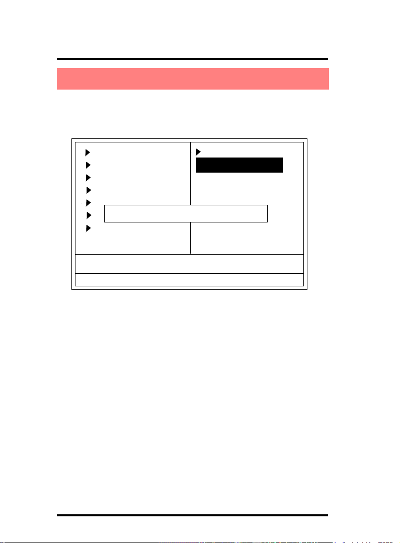
2.11 Load Fail-Safe Defaults
When you press <Enter> on this item, you get a confirmation
dialog box with a message similar to below:
Phoenix - AwardBIOS CMOS Setup Utility
Standard CMOS Features
Advanced BIOS Features
Advanced Chipset Features
Integrated Peripherals
Power Management Setup
Load Fail-Safe Default (Y/N)? N
PNP/PCI Configurations
PC Health Status
Esc : Quit F9 : Menu in BIOS ←→↑↓: Select Item
F10 : Save & Exit Setup
Time , Date , Hard Disk Type ...
Frequency/Voltage Control
Load Fail-safe Defaults
Load Optimized Defaults
Set Supervisor Password
Set User Password
Save & Exit Setup
Exit without Saving
Pressing ‘Y’ loads the default values that are factory settings
for optimal performance of system operations.
2-66
Page 67
Chapter 2 7KT400A BIOS Setup
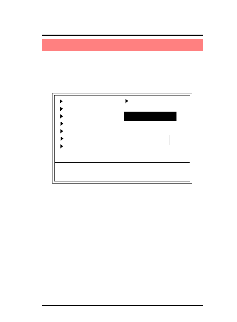
2.12 Load Optimized Defaults
When you press <Enter> on this item, you get a confirmation
dialog box with a message similar to:
Phoenix - AwardBIOS CMOS Setup Utility
Standard CMOS Features
Advanced BIOS Features
Advanced Chipset Features
Integrated Peripherals
Power Management Setup
PNP/PCI Configurations
Load Optimized Default (Y/N)? N
PC Health Status
Esc : Quit F9 : Menu in BIOS ←→↑↓: Select Item
F10 : Save & Exit Setup
Time , Date , Hard Disk Type ...
Frequency/Voltage Control
Load Fail-safe Defaults
Load Optimized Defaults
Set Supervisor Password
Set User Password
Save & Exit Setup
Exit without Saving
Pressing ‘Y’ loads the default values that are factory settings
for optimal performance of system operations.
2-67
Page 68
Chapter 2 7KT400A BIOS Setup
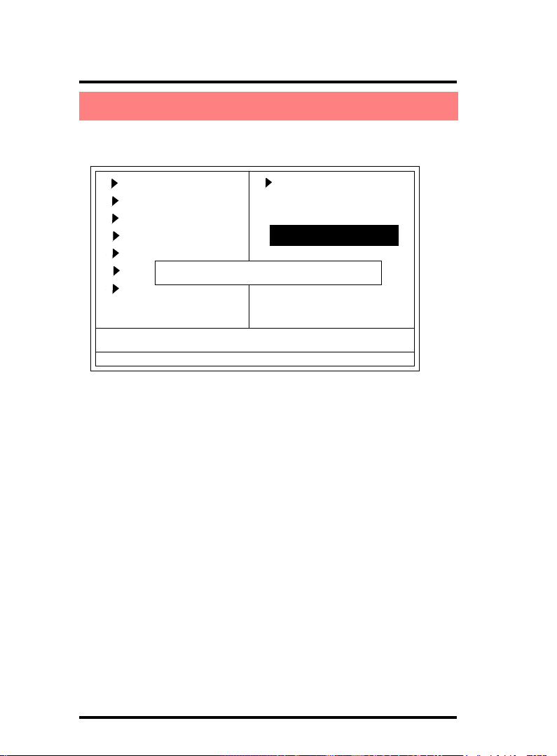
2.13 Set Supervisor / User Password
Phoenix - AwardBIOS CMOS Setup Utility
Standard CMOS Features
Advanced BIOS Features
Advanced Chipset Features
Integrated Peripherals
Power Management Setup
PNP/PCI Configurations
PC Health Status
Esc : Quit F9 : Menu in BIOS ←→↑↓: Select Item
F10 : Save & Exit Setup
Enter Password:
Time , Date , Hard Disk Type ...
Frequency/Voltage Control
Load Fail-safe Defaults
Load Optimized Defaults
Set Supervisor Password
Set User Password
Save & Exit Setup
Exit without Saving
When you select this function, the following message will appear
at the center of the screen to assist you in creating a password.
Enter Password (for Supervisor/User)
Type a password, up to eight characters, and press <Enter>.The
password you type now will clear any previously entered
password from CMOS memory. You will be asked to confirm the
password. Type the password again and press <Enter>. You
may also press <ESC> to abort the selection and not enter a
password. To disable the password, just press <Enter> when
you are prompted to enter a password. A message will confirm
that you wish to disable the password. Once the password is
disabled, the system will boot without asking user to enter a
password.
Password for System or BIOS Setup
If you select “System” at the Security Option of BIOS Features
Setup Menu, you will be prompted for the password every time
when the system is rebooted, or any time when you try to enter
Setup. If you select “Setup” at the Security Option of BIOS
Features Setup Menu, you will be prompted only when you try
to enter Setup.
2-68
Page 69
Chapter 2 7KT400A BIOS Setup
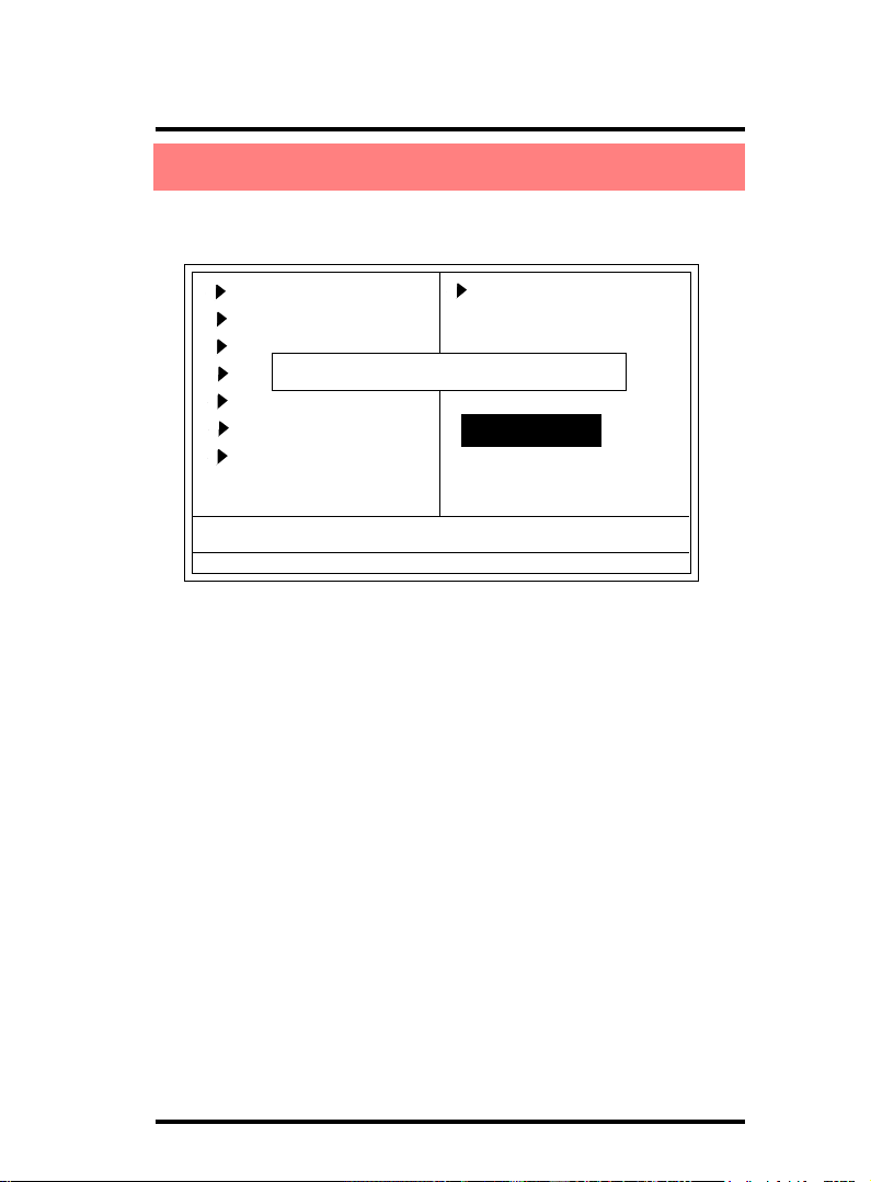
2.14 Save & Exit Setup
Phoenix - AwardBIOS CMOS Setup Utility
Standard CMOS Features
Advanced BIOS Features
Advanced Chipset Features
Integrated Peripherals
Power Management Setup
PNP/PCI Configurations
PC Health Status
Esc : Quit F9 : Menu in BIOS ←→↑↓: Select Item
F10 : Save & Exit Setup
Save to CMOS & Exit (Y/N)? Y
Time , Date , Hard Disk Type ...
Frequency/Voltage Control
Load Fail-safe Defaults
Load Optimized Defaults
Set Supervisor Password
Set User Password
Save & Exit Setup
Exit without Saving
Typing “Y” will quit the Setup Utility and save the user setup
value to RTC CMOS RAM.
Typing “N” will return to the Setup Utility.
2-69
Page 70
Chapter 2 7KT400A BIOS Setup
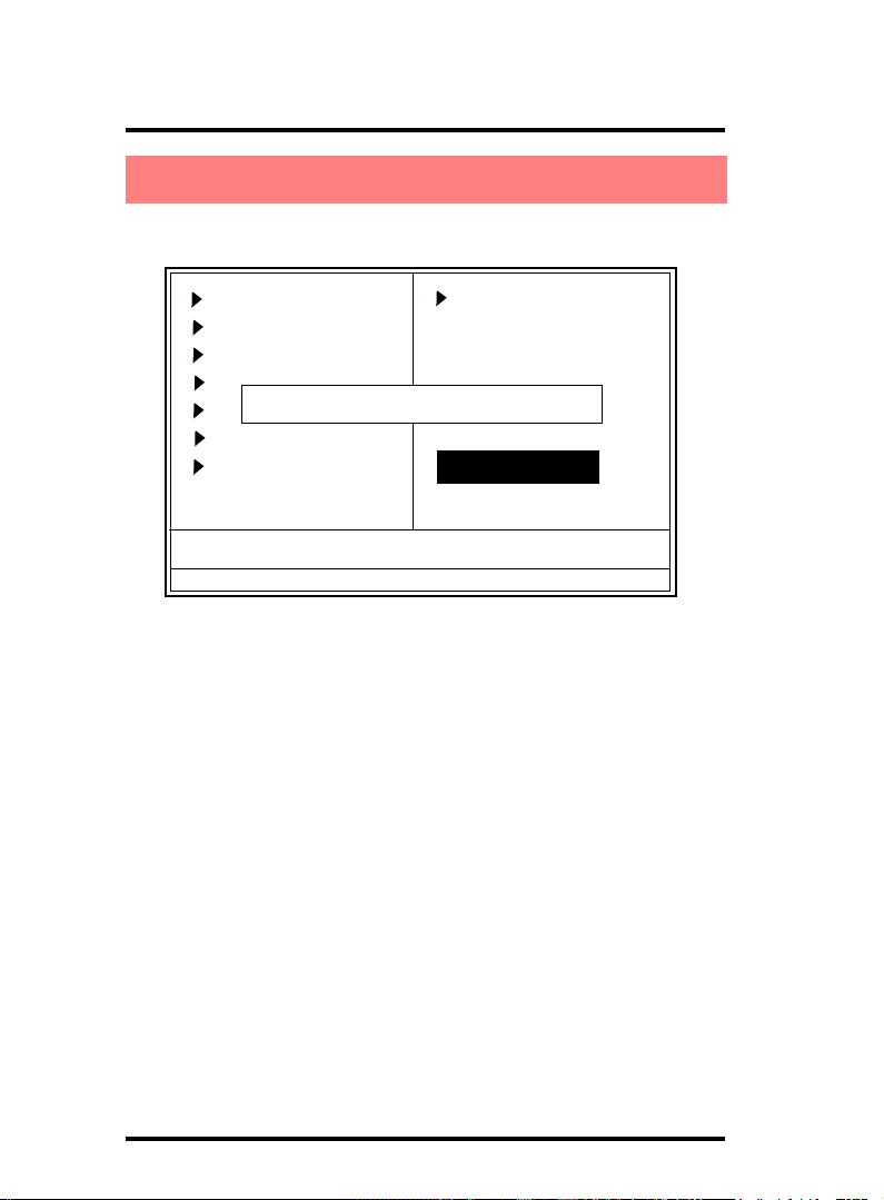
2.15 Exit Without Saving
Phoenix - AwardBIOS CMOS Setup Utility
Standard CMOS Features
Advanced BIOS Features
Advanced Chipset Features
Integrated Peripherals
Quit Without Saving (Y/N)? N
Power Management Setup
PNP/PCI Configurations
PC Health Status
Esc : Quit F9 : Menu in BIOS ←→↑↓: Select Item
F10 : Save & Exit Setup
Time , Date , Hard Disk Type ...
Frequency/Voltage Control
Load Fail-safe Defaults
Load Optimized Defaults
Set Supervisor Password
Set User Password
Save & Exit Setup
Exit without Saving
Typing “Y” will quit the Setup Utility without saving to RTC
CMOS RAM.
Typing “N” will return to the Setup Utility.
2-70
Page 71

Chapter 3 7KT400A Drivers & Utilities
Chapter 3
Drivers & Utilities
3. Drivers & Utilities
There are motherboard drivers and utilities included in
the disc attached in this motherboard package. You don't
have to install all of them for booting your system. But after
you have finished the hardware installation, you have to install an operation system (such as windows XP) before you
are able to install any drivers or utilities.
Note: Please be aware of the different Procedures for installing
drivers for Windows 98/ME/XP/2000 .
3.1 Auto-run Menu
You can use the auto-run menu in the driver CD attached in
the motherboard package. Then choose the utility or driver and
select model name. The autorun starting screen looks like below:
3-71
Page 72

Chapter 3 7KT400A Drivers & Utilities
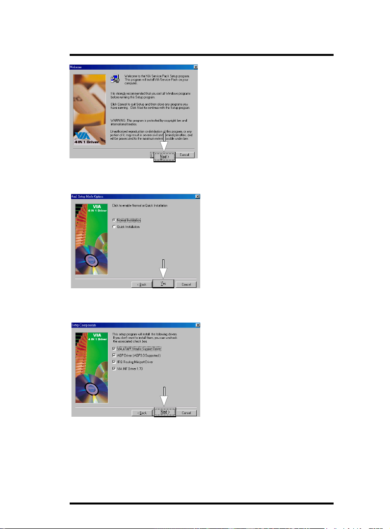
3.2 Installing VIA Service Pack
Enter the item "Chipset" of the Autorun program and install
the VIA Service Pack. Follow the illustrations below :
(1)
Click "Driver" Item.
(2)
Click "Chipset" Item.
Click "VIA service Pack"
3-72
(3)
Item.
Page 73
Chapter 3 7KT400A Drivers & Utilities
(4)
Click "Next".
(5)
Click "Yes".
(6)
Tick all four items and
click "Next".
3-73
Page 74
Chapter 3 7KT400A Drivers & Utilities
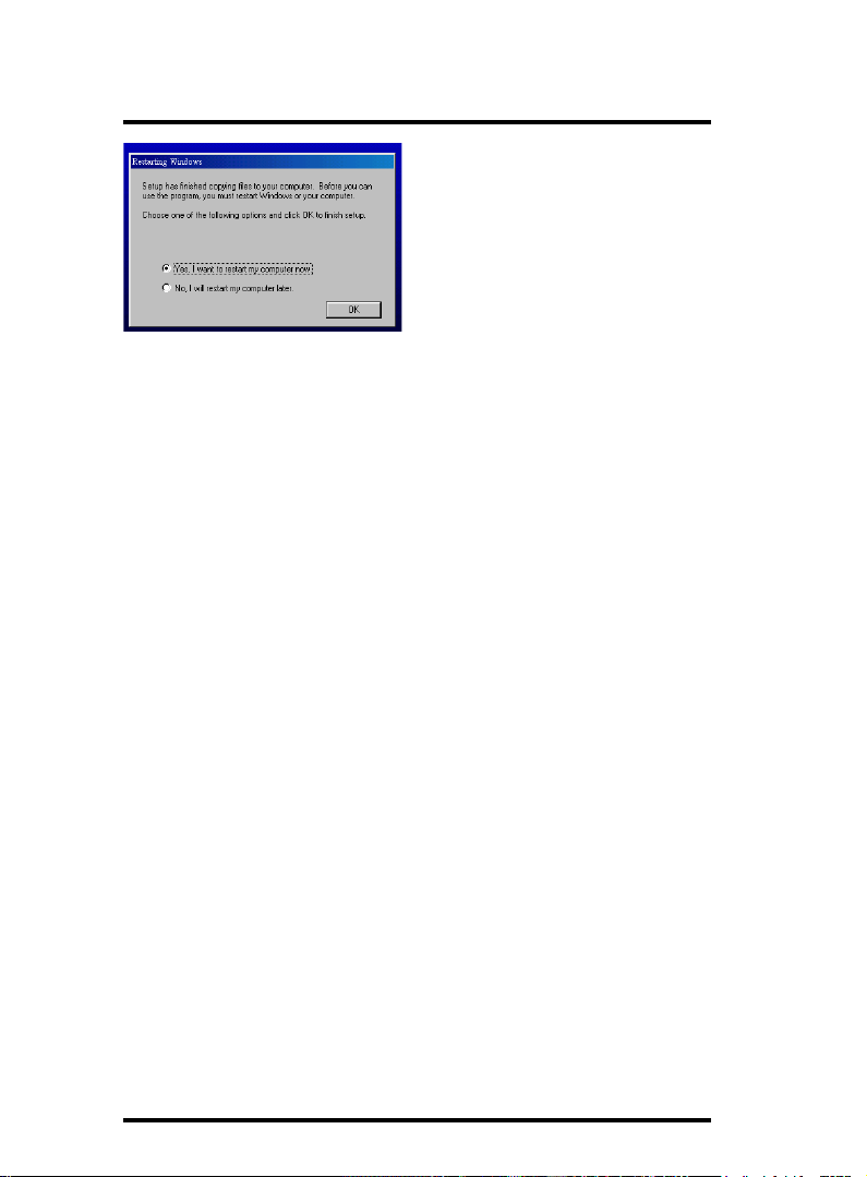
(7)
The Setup Program will install all
items until the Restart screen
appears. Click "OK" to restart
system.
3-74
Page 75

Chapter 3 7KT400A Drivers & Utilities
3.3 Installing Audio Driver
This motherboard comes with an AC97 CODEC V2.2, 6-channel compatible. You can find the Audio driver from this Auto-run
menu.
(1)
Click "Driver" Item.
(2)
Click "Audio" Item.
3-75
(3)
Click "ALC650" Item.
Page 76
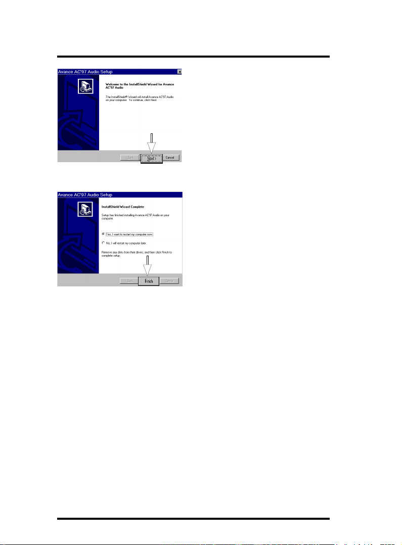
Chapter 3 7KT400A Drivers & Utilities
(4)
Click "Next".
(5)
Click "Finish".
3-76
Page 77

Chapter 3 7KT400A Drivers & Utilities
3.4 Installing USB 2.0 Driver
(1)
Click the "Driver "
item.
(2)
Click the "USB " item.
3-77
(3)
Click the "USB2.0 "
item.
Page 78
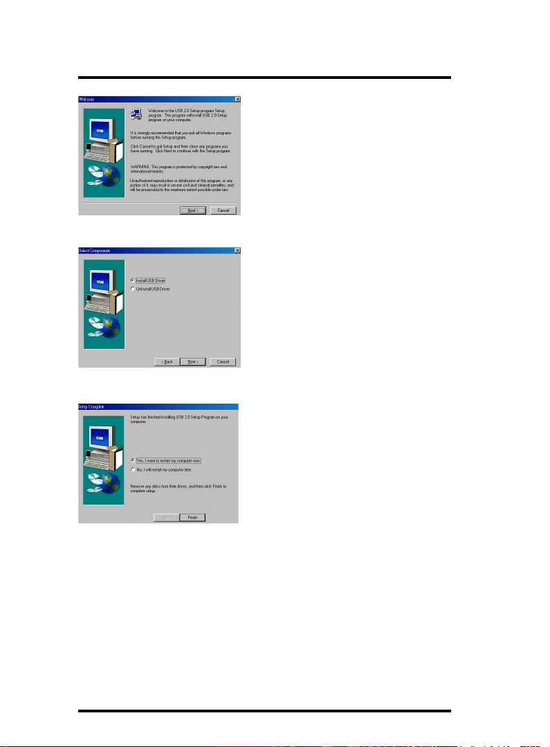
Chapter 3 7KT400A Drivers & Utilities
(4)
Click the "Next " item.
(2)
Tick "Install USB
Driver" and click the
"Next " item.
(6)
Click the "Finish " item
to restart system.
3-78
Page 79
Appendices
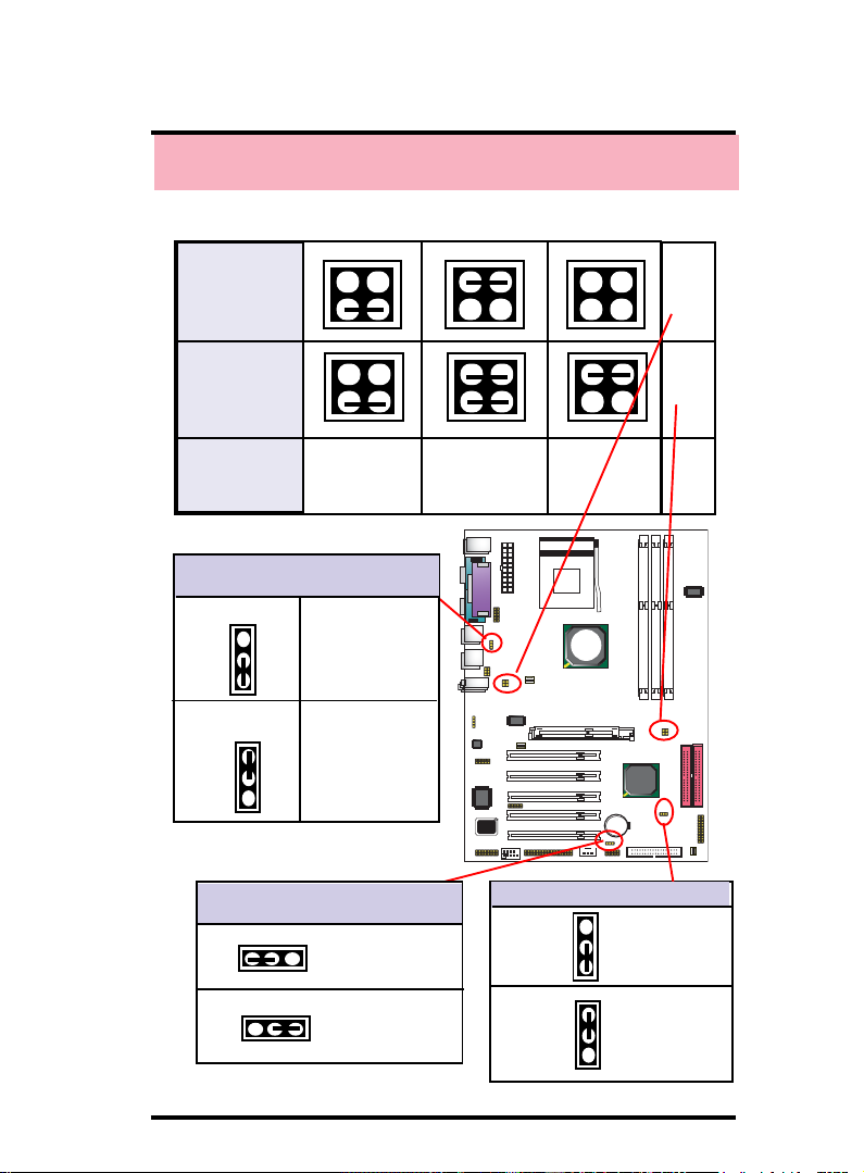
Appendices
Appendix I Quick Jumper Setup
J3 Setting
J5 Setting
4
2
4
2
CPU(MHz) 166 MHz
J2: USB0/1, 2/3 Wake-up
Selector
1-2 closed
1
2-3 closed
1
JP4: USB4/5 Wake-up Selector
1-2 Disabled
1
(default)
2-3 Enabled
1
Disabled
(Default)
Enabled
3
1
3
1
4
2
4
2
100 MHz
3
4
1
2
3
4
1
2
3
1
3
1
133 MHz
(default)
Socket 462
VIA
KT400
8100BL
RTL
VIA
W83697
BIOS
Jumper Clear CMOS
1-2 Normal
closed (Default)
2-3 Clear CMOS
closed
VT8235
1
1
J3
J5
4-79
Page 80
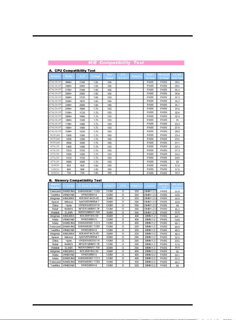
Appendices
Appendix II Mainboard Test Report
4-80
Page 81

Appendices
4-81
 Loading...