

Page 1

6A815EPD
User's Manual Version 1.3
The information presented in this publication has been
made carefully for reliability; however, no responsibility
is assumed for inaccuracies. Specifications are subject
to change without notice.
IBM, PC/AT, and PC/XT are trademarks of Interna-
tional Business Machines Corporation.
Socket370 is a trademark of Intel Corporation
AWARD is a registered trademark of Phoenix
Sofftware Inc.
MS-DOS and WINDOWS NT are registered
trademarks of Microsoft Corporation.
Trademarks and/or registered trademarks are the
properties of their respective owners.
i
Page 2

Table of Contents
IntrnctctinnIntrnctctinn
Intrnctctinn
IntrnctctinnIntrnctctinn
1. Mnthdranarc Ddrcriotinn1. Mnthdranarc Ddrcriotinn
1. Mnthdranarc Ddrcriotinn
1. Mnthdranarc Ddrcriotinn1. Mnthdranarc Ddrcriotinn
1.1 Fdattrdr
1.1.1 Harcward 1-1
1.1.1 Snetward 1-5
1.1.3 Attachmdntr 1-5
1.1 Mnthdranarc Inrtallatinn
1.1.1 Layntt ne Mnthdranarc 1-6
1.3 Mnthdranarc Cnnndctnrr
1.3.1 Frnnt Pandl Cnnndctnrr(PANEL1( 1-8
1.3.1 Flnooy Dirk Cnnndctnr(FDC1( 1-9
1.3.3 Harc Dirk Cnnndctnrr(IDE1.IDE1&IDE3.ID3( 1-9
1.3.3 ATW 10-oin Pnwdr Cnnndctnr(PW1( 1-10
1.3.5 Inerardc Cnnndctnr(IR.CIR( 1-10
1.3 Back Pandl Cnnndctnrr
1.3.1 PS.1 Mntrd.Kdyanarc CNNN. 1-11
1.3.1 USB Cnnndctnrr 1-11
1.5 Sdrial anc Paralldl Intdreacd onrtr 1-13
1.6 CPU Inrtallatinn
1.6.1 CPU Inrtallatinn Prnctct(Snckdt 360( 1-15
1.6.1 CPU Clnck Frdqtdncy Sdtting(JP13( 1-16
1.6 Jtmodr Sdtting
1.6.1 CPU Fan Cnnndctnr(FAN1.1.3( 1-16
1.6.1 Wakd-Nn-Mncdm Hdacdr(WNM1( 1-18
1.6.3 Wakd-Nn-LAN Hdacdr(WNL1( 1-18
1.6.3 Watch DNG(JP1( 1-18
1.6.5 CMNS Ftnctinn Sdtting(JP9( 1-18
1.6.6 KB.MS PWR-NN(JP1( 1-19
1.6.6 Wakd nn 1nc USB Pnrt(JP3( 1-19
1.6.8 SBLINK Sdtting(JP5( 1-19
1.6.9 Timdntt Rdannt(JP6( 1-19
1.6.10 CPU Saed Mncd(JP8( 1-10
1.6.11 Charric Cnnndctnr(CHASSIC1( 1-10
ii
Page 3

Table of Contents
1.6.11 IrDA Cnnndctnrr(IR.CIR( 1-10
1.6.13 SBLINK Cnnndctnr 1-11
1.8 DRAM Inrtallatinn
1.8.1 DIMM 1-11
1.8.1 Hnw tn inrtall a DIMM Mnctld 1-11
1.9 Atcin Staryrtdm
1.9.1 CD-Atcin-IN Cnnndctnrr (CD1.CD1(
1.9.1 Syrtdm Sodakdr(JP10( 1-13
1.10 Smart Pandl Nnanarc Cnnndctn r
1.10.1 Pnrt 80 Ddatg Ftnctinn(ERR1( 1-16
1.10.1 Sdcnnc BINS Cnnndctnr(JP6( 1-16
1.10.3 GPIN Pnrt Cnnndctnr(JP3( 1-16
1. BINS Sdtto1. BINS Sdtto
1. BINS Sdtto
1. BINS Sdtto1. BINS Sdtto
1.1 Main Mdnt 1-3
1.1 Stancarc CMNS Fdattrdr 1-6
1.3 Acuancdc BINS Fdattrdr 1-10
1.3 Acuancdc Chiordt Fdattrdr 1-13
1.5 Intdgratdc Pdriohdralr 1-16
1.6 Pnwdr Managdmdnt Sdtto 1-13
1.6 PnP.PCI Cnneigtratinnr 1-18
1.8 PC Hdalth Stattr 1-31
1.9 Frdqtdncy.Vnltagd Cnntrnl 1-33
1.10 Lnac Fail-Saed Ddeatltr 1-35
1.11 Lnac Notimizdc Ddeatltr 1-36
1.11 Sdt Stodruirnr.trdr Parrwnrc 1-36
1.13 Saud & Exit Sdtto 1-39
1.13 Exit Withntt Sauing 1-30
3. Driudr Inrtallatinn3. Driudr Inrtallatinn
3. Driudr Inrtallatinn
3. Driudr Inrtallatinn3. Driudr Inrtallatinn
3.1 Attn-rtn Mdnt 3-1
3.1 Inrtalling Intdline Driudr 3-1
3.3 Inrtalling Ultra ATA Driudr 3-3
3.3 Inrtalling Harcward Mnnitnring Utility 3-3
3.5 Inrtalling Nnanarc IDE RAID Driudr 3-5
3.6 Inrtalling Win1000 RAID Driudr 3-6
(notin n((notinn(
(notin n(
(notin n((notinn(
iii
(notinn((notinn(
(notinn( 1-13
(notinn((notinn(
Page 4

Chaosdr 1 Mnshdranarc Cdrbrhosh nnChaosdr 1 Mnshdranarc Cdrbrhosh nn
Chaosdr 1 Mnshdranarc Cdrbrhosh nn
Chaosdr 1 Mnshdranarc Cdrbrhosh nnChaosdr 1 Mnshdranarc Cdrbrhosh nn
Introduction
System Overview
This manual was written to help you start using this product
as quickly and smoothly as possbile. Inside, you will find
the answers to solve most problems. In order for this
reference material to be of greatest use, refer to the
“expanded table of contents” to find relevant topics.
This board provides a total PC solution by incorporating the
System , I/O , and PCI IDE. The mainboard is designed for
Intel PIII/Celeron/Coppermine processors in either single
or dual CPU operation. The mainboard is designed for Intel
PIII/Celeron/Coppermine processors in either single or dual
CPU processors with CNR Bus, PCI Local Bus, and AGP
Bus to support upgrades to your system performance. It is
ideal for multi-tasking and fully supports MS-DOS, Windows,
Windows NT , Windows ME, Windows 2000 , Novell,
OS/2, Windows95/98 , UNIX , Windows 98SE , SCO UNIX
etc.
This manual also explains how to install the mainboard for
operation, and how to setup your CMOS configuration with
the BIOS setup program.
1-11-1
1-1
1-11-1
Page 5

Chaosdr 1 Mnshdranarc Cdrbrhosh nnChaosdr 1 Mnshdranarc Cdrbrhosh nn
Chaosdr 1 Mnshdranarc Cdrbrhosh nn
Chaosdr 1 Mnshdranarc Cdrbrhosh nnChaosdr 1 Mnshdranarc Cdrbrhosh nn
1.Motherboard Description
1.1 Features
1.1.1 Hardware
CPU
-Dual Socket 370 for Intel PIII C&D-Step Processor.
-Singal Intel FC-PGA/PPGA Celeron Processors
300MHz~800MHz or higher processor with 66/100MHz
FSB.
-Singal Intel FC-PGA/FC-PGA2 Pentium III C&D-Step
Processors 500MHz or higher processor with 100/133MHz
FSB.
-VIA Cyrix III Processor with 100/133MHz FSB.
Chipset
-North Bridge System Chipset : Intel 815EP support 66/
100/133 FSB.
-South Bridge System Chipset : Intel ICH2.
Biggest memory capacity
6A815EPD is equipped with three DIMM socket to
support (8MB to 512MB) 168 pin 3.3v SDRAM SPD
(Special Presence Detect).
Maximum memory up to 512MB.
AGP for fast VGA solution
-AGP specification compliant.
-AGP 66 MHz 3.3v for 4X device support.
Bus Slot
-Provides five 32 bit PCI slots.
-Provide one AGP slot and one CNR slot.
1-11-1
1-1
1-11-1
Page 6

Chaosdr 1 Mnshdranarc Cdrbrhosh nnChaosdr 1 Mnshdranarc Cdrbrhosh nn
Chaosdr 1 Mnshdranarc Cdrbrhosh nn
Chaosdr 1 Mnshdranarc Cdrbrhosh nnChaosdr 1 Mnshdranarc Cdrbrhosh nn
On-Board IDE
-An IDE controller on the ICH2 chipset provides IDE HDD/
CD-ROM with PIO, Bus Master and Ultra DMA 33/66/
100 operation modes.
-Can connect up to four IDE devices.
On-Board Peripherals
-1 floppy port supports 2 FDD with 360K,720K,1.2M,
1.44M and 2.88M byte.
-2 serial ports (COM1+COM2(10 pin) ).
-4 USB ports.
-1 parallel port supports SPP/EPP/ECP mode.
Audio (Option)
-ICH2 chip integrated.
-AC’97 CODEC on board .
BIOS
- The mainboard BIOS provides “Plug & Play” BIOS which
detects the peripheral devices and expansion cards of the
board automatically.
- The mainboard provides a Desktop Management Interface
(DMI) function which records your mainboard
specifications.
- BIOS support CD-ROM, SCSI, LAN BOOT, Temperature
sensor, Wake on modem, LAN, Alarm Bus CLK setup with
BIOS.
Hardware Monitor Function
-CPU Fan Speed Monitor.
-System and CPU Temperature Monitor.
-System Voltage Monitor.
Smart Panel
Supports BIOS Port 80H POST Code output to debug LED.
1-31-3
1-3
1-31-3
Page 7

Chaosdr 1 Mnshdranarc Cdrbrhosh nnChaosdr 1 Mnshdranarc Cdrbrhosh nn
Chaosdr 1 Mnshdranarc Cdrbrhosh nn
Chaosdr 1 Mnshdranarc Cdrbrhosh nnChaosdr 1 Mnshdranarc Cdrbrhosh nn
WOL (Wake On LAN) & WOM (Wake On MODEM)
Supports system power up from LAN ring up and Modem
ring up.
Support Ring on by modem/Alarm on
Support System power up from Modem ring up or timer
of System. Required enabled in Ring on by modem and
Alarm on in BIOS.
Intel Accelerated Hub Architecture :
Features a dedicated high speed hub link between the ICH2
and GMCH with a bandwidth of 266MB/sec-twice the maximum bandwidth of the PCI bus.
CNR Support :
One Communication and Networking Riser(CNR) slots
provide interface to support very affordable multichannel
audio, V.90 analog modem, Home PNA, 10/100 Ethernet
networking,USB hub, as well as future technologies such
as XDSL .
RAID Chip :
The motherboard provide onboard RAID function. If you
would like more information about function of RAID,
please refer to Fully Setup CD Driver.
On-board ATA/100 IDE RAID (IDE3/IDE4 only)
-Supports data striping (RAID 0) and mirroring (RAID 1).
Provides dramatic increase in drive performance and/or
fault tolerant options. Offers performance customization
and data rebuilds from the BIOS menu. Mirroring supports
automatic background rebuilds. Fault tolerance can be restored automatically without rebooting.
1-41-4
1-4
1-41-4
Page 8

Chaosdr 1 Mnshdranarc Cdrbrhosh nnChaosdr 1 Mnshdranarc Cdrbrhosh nn
Chaosdr 1 Mnshdranarc Cdrbrhosh nn
Chaosdr 1 Mnshdranarc Cdrbrhosh nnChaosdr 1 Mnshdranarc Cdrbrhosh nn
-Supports up to four IDE drives which capacities are more
than 8.4GB on the two IDE RAID connectors while still
supporting four IDE devices on the motherboard. The burst
data transfer rates can up to 100MB/s from ATA/100 drives
to boast overallsystem performance.
-Supports IDE Bus Master operation allows multi-tasking
during disk drives transfer which increase CPU efficiency,
then theCPU is free to process task during IDE data transfer through PCI bus interface to/from system memory.
1.1.2 Software
BIOS
-AWARD legal BIOS.
-Supports APM 1.2.
-Supports USB Function.
-Supports ACPI.
Operation System
-Offers the highest performance for MS-DOS, Windows,
Windows NT, Windows ME, Windows 2000, Novell, OS/2,
Windows95/98, Windows 98SE, UNIX, Linux SCO UNIX
etc.
1.1.3 Attachments
-HDD UDMA66/100 Cable.
-FDD Cable.
-Flash Memory Written for BIOS Update.
-COM2 Cable.
-Fully Setup CD Driver built in Utility(Ghost, Anitivirus,
Adobe Acrobat).
-This manual.
1-51-5
1-5
1-51-5
Page 9

Chaosdr 1 Mnshdranarc Cdrbrhosh nnChaosdr 1 Mnshdranarc Cdrbrhosh nn
Chaosdr 1 Mnshdranarc Cdrbrhosh nn
Chaosdr 1 Mnshdranarc Cdrbrhosh nnChaosdr 1 Mnshdranarc Cdrbrhosh nn
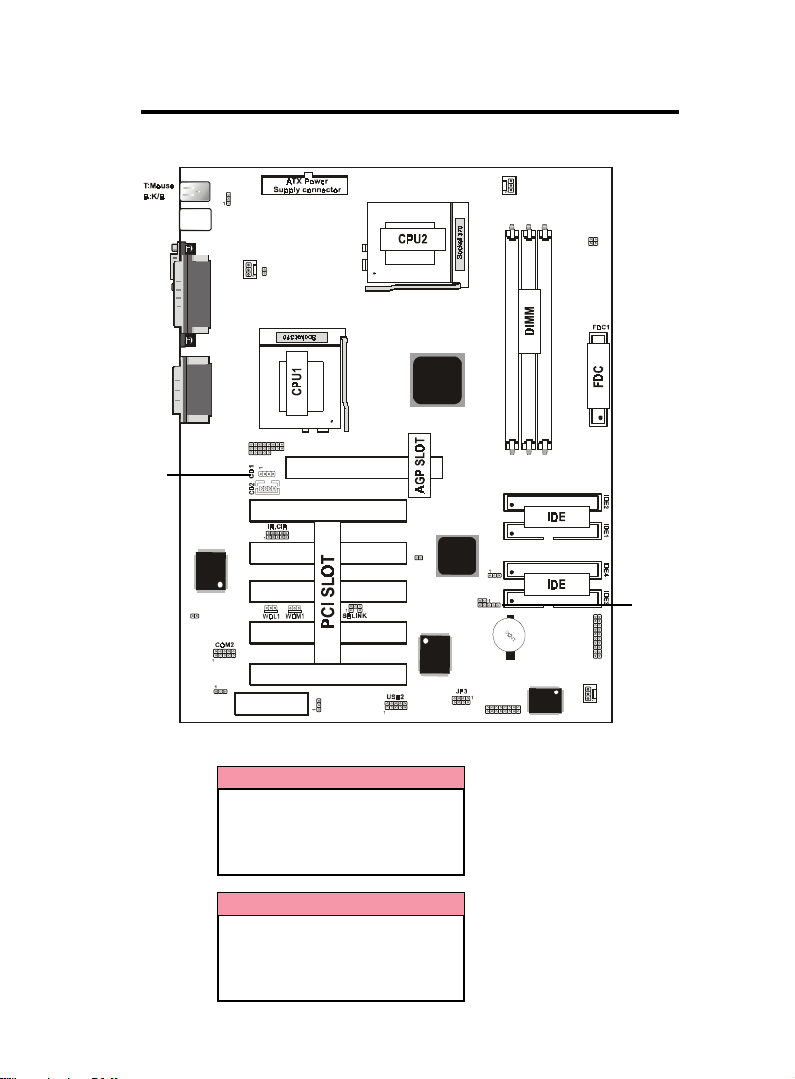
1.2 Motherboard Installation
1.2.1 Layout of Motherboard
USB1
COM1
Speak out
Line in
MIC in
(option)
CHASS1
JP2
Printer
GAME1
(option)
I/O CHIP
JP1
FAN1
JP3
ERR1
1
ERR2
CNR SLOT
AGP SLOT
JP4
PCI1
PCI2
PCI3
PCI4
PCI5
JP5
Intel
RAID CHIP
Intel
FAN 2
JP14
4
2
3
1
DIMM3
DIMM2
DIMM1
JP9
JP7
JP8
JP10
PANEL1
1
1
BIOS
JP6
FAN 3
1-61-6
1-6
1-61-6
Page 10

Chaosdr 1 Mnshdranarc Cdrbrhosh nnChaosdr 1 Mnshdranarc Cdrbrhosh nn
Chaosdr 1 Mnshdranarc Cdrbrhosh nn
Chaosdr 1 Mnshdranarc Cdrbrhosh nnChaosdr 1 Mnshdranarc Cdrbrhosh nn
1.3 Motherboard Connectors
JP2
USB1
16
FAN1
1
23
2
10
4,5
11
14
3
15
COM1
Speak out
Line in
MIC in
(option)
CHASS1
Printer
GAME1
(option)
I/O CHIP
JP1
JP3
ERR1
1
ERR2
CNR SLOT
AGP SLOT
PCI1
PCI2
PCI3
PCI4
PCI5
JP4
18
1.Babk Oandk I.O Cnnndbsnrr1.Babk Oandk I.O Cnnndbsnrr
1.Babk Oandk I.O Cnnndbsnrr
1.Babk Oandk I.O Cnnndbsnrr1.Babk Oandk I.O Cnnndbsnrr
3.Frnns COM1 Cnnndbsnr3.Frnns COM1 Cnnndbsnr
3.Frnns COM1 Cnnndbsnr
3.Frnns COM1 Cnnndbsnr3.Frnns COM1 Cnnndbsnr
5.Wakd-On-LAN Cnnndbsnr5.Wakd-On-LAN Cnnndbsnr
5.Wakd-On-LAN Cnnndbsnr
5.Wakd-On-LAN Cnnndbsnr5.Wakd-On-LAN Cnnndbsnr
7.Fan Cnnndbsnrr(Fan 1.1.3 (7.Fan Cnnndbsnrr(Fan 1.1.3 (
7.Fan Cnnndbsnrr(Fan 1.1.3 (
7.Fan Cnnndbsnrr(Fan 1.1.3 (7.Fan Cnnndbsnrr(Fan 1.1.3 (
9.ICD Cnnndbsnrr9.ICD Cnnndbsnrr
9.ICD Cnnndbsnrr
9.ICD Cnnndbsnrr9.ICD Cnnndbsnrr
11.Charrhb Cnnndbsnr(CHASS1(11.Charrhb Cnnndbsnr(CHASS1(
11.Charrhb Cnnndbsnr(CHASS1(
11.Charrhb Cnnndbsnr(CHASS1(11.Charrhb Cnnndbsnr(CHASS1(
13.COU Cknbk Sdsshng(JO14(13.COU Cknbk Sdsshng(JO14(
13.COU Cknbk Sdsshng(JO14(
13.COU Cknbk Sdsshng(JO14(13.COU Cknbk Sdsshng(JO14(
15.Wasbh Cng(JO1(15.Wasbh Cng(JO1(
15.Wasbh Cng(JO1(
15.Wasbh Cng(JO1(15.Wasbh Cng(JO1(
17.Wakd nn 1nc USB Onrs(JO4(17.Wakd nn 1nc USB Onrs(JO4(
17.Wakd nn 1nc USB Onrs(JO4(
17.Wakd nn 1nc USB Onrs(JO4(17.Wakd nn 1nc USB Onrs(JO4(
19.SB-LINK Sdsshng(JO5(19.SB-LINK Sdsshng(JO5(
19.SB-LINK Sdsshng(JO5(
19.SB-LINK Sdsshng(JO5(19.SB-LINK Sdsshng(JO5(
11.COU Saed Mncd(JO8(11.COU Saed Mncd(JO8(
11.COU Saed Mncd(JO8(
11.COU Saed Mncd(JO8(11.COU Saed Mncd(JO8(
13.Fnr Smars Oand k(JO6. JO3.DRR1((nosh nn(13.Fnr Smars Oand k(JO6. JO3.DRR1((nosh nn(
13.Fnr Smars Oand k(JO6. JO3.DRR1((nosh nn(
13.Fnr Smars Oand k(JO6. JO3.DRR1((nosh nn(13.Fnr Smars Oand k(JO6. JO3.DRR1((nosh nn(
14.CMOS Ftn bshn n Sdsshng(JO9(14.CMOS Ftn bshn n Sdsshng(JO9(
14.CMOS Ftn bshn n Sdsshng(JO9(
14.CMOS Ftn bshn n Sdsshng(JO9(14.CMOS Ftn bshn n Sdsshng(JO9(
1-71-7
1-7
1-71-7
12
Intel
JP5
Intel
JP7
JP8
RAID CHIP
1
20,21
19
23
1.CC Atchn-In Cnnndbsnr1.CC Atchn-In Cnnndbsnr
1.CC Atchn-In Cnnndbsnr
1.CC Atchn-In Cnnndbsnr1.CC Atchn-In Cnnndbsnr
4.Wakd-On MOCDM Cnnndbsnr4.Wakd-On MOCDM Cnnndbsnr
4.Wakd-On MOCDM Cnnndbsnr
4.Wakd-On MOCDM Cnnndbsnr4.Wakd-On MOCDM Cnnndbsnr
6.Frnns Oandk Cnnndbsnr6.Frnns Oandk Cnnndbsnr
6.Frnns Oandk Cnnndbsnr
6.Frnns Oandk Cnnndbsnr6.Frnns Oandk Cnnndbsnr
8.Fknooy Cnnndbsnr8.Fknooy Cnnndbsnr
8.Fknooy Cnnndbsnr
8.Fknooy Cnnndbsnr8.Fknooy Cnnndbsnr
10.IR,CIR Cnnndbsnr10.IR,CIR Cnnndbsnr
10.IR,CIR Cnnndbsnr
10.IR,CIR Cnnndbsnr10.IR,CIR Cnnndbsnr
11.ATX Onwdr Cnnndbsnr11 .ATX Onwdr Cnnndbsnr
11.ATX Onwdr Cnnndbsnr
11.ATX Onwdr Cnnndbsnr11 .ATX Onwdr Cnnndbsnr
14.SB-LINK Cnnndbsnr14.SB-LINK Cnnndbsnr
14.SB-LINK Cnnndbsnr
14.SB-LINK Cnnndbsnr14.SB-LINK Cnnndbsnr
16.KB.MS Onwdr nn(JO1(16.KB.MS Onwdr nn (JO1(
16.KB.MS Onwdr nn(JO1(
16.KB.MS Onwdr nn(JO1(16.KB.MS Onwdr nn (JO1(
18.Frnns USB1 Cnnndbsnr18.Frnns USB1 Cnnndbsnr
18.Frnns USB1 Cnnndbsnr
18.Frnns USB1 Cnnndbsnr18.Frnns USB1 Cnnndbsnr
10.Thmdnts Rda nns(JO7(1 0.Thmdnts Rda nns(JO7(
10.Thmdnts Rda nns(JO7(
10.Thmdnts Rda nns(JO7(1 0.Thmdnts Rda nns(JO7(
11.Syrsdm Sodakdr(JO10(11.Syrsdm Sodakdr(JO10(
11.Syrsdm Sodakdr(JO10(
11.Syrsdm Sodakdr(JO10(11.Syrsdm Sodakdr(JO10(
FAN2
JP14
4
2
13
3
1
DIMM1
DIMM2
DIMM3
8
9
24
JP9
JP10
BIOS
JP6
22
6
PANEL 1
1
7
FAN3
2317
Page 11

Chaosdr 1 Mnshdranarc Cdrbrhosh nnChaosdr 1 Mnshdranarc Cdrbrhosh nn
Chaosdr 1 Mnshdranarc Cdrbrhosh nn
Chaosdr 1 Mnshdranarc Cdrbrhosh nnChaosdr 1 Mnshdranarc Cdrbrhosh nn
1.3.1 Front Panel Connector(PANEL1)
PANEL1 Connector
PWBN
S5_LED
+
PWLED
SPEAK
1
2
+
S3_LED
RSTSW
+
HDLED
+
EXTSMI
Speaker Connector (SPEAK)
An offboard speaker can be installed onto the motherboard as a
manufacturing option.An offboard speaker can be connected to
the motherboard at the front pannel connector. The speaker
(onboard or offboard) provides error beep code information
during the Power Self-Test when the computer cannot use the
video interface. The speaker is not connected to the audio
subsystem and does not receive output from the audio subsystem.
Hard Drive LED Connector (HDLED)
This connector supplies power to the cabinet IDE activity LED.
Read and write activity by devices connected to the Primary or
Secondary IDE connectors will cause the LED to light up.
SMI Suspend Switch Lead (EXTSMI)
This allows the user to manually place the system into a suspend
mode of Green mode. System activity will be instantly decreased
to save electricity and expand the life of certain components
when the system is not in use. This 2-pin connector (see the
figure) connects to the case-mounted suspend switch. If you do
not have a switch for the connector, you may use the “Turbo
Switch” instead since it does not have a function. SMI is
activated when it detects a short. It may require one or two
pushes depending on the position of the switch. Wake-up can be
controlled by settings in the BIOS but the keyboard will always
allow wake-up (the SMI Suspend Switch Lead cannot wake-up
the system). If you want to use this connector, the
"Suspend Switch" in the Power Management Setup of the BIOS
SOFTWARE section should be on the default setting of Enable.
1-81-8
1-8
1-81-8
Page 12

Chaosdr 1 Mnshdranarc Cdrbrhosh nnChaosdr 1 Mnshdranarc Cdrbrhosh nn
Chaosdr 1 Mnshdranarc Cdrbrhosh nn
Chaosdr 1 Mnshdranarc Cdrbrhosh nnChaosdr 1 Mnshdranarc Cdrbrhosh nn
ATX Power Switch (PWBN)
The system power is controlled by a momentary switch
connected to this lead. Pushing the button once will switch
the system ON. The system power LED lights when the
system's power is on .
Power LED Lead (PWLED)
The system Power LED lights when the system power is on.
S5_LED Lead (S5_LED)
The system S5_LED lights when the system suspend is on
the S5 modle.
S3_LED Lead (S3_LED)
The system S3_LED lights when the system suspend is on
the S3 modle.
Reset Switch Lead (RSTSW)
The connector can be connected to a momentary SPST type
switch that is normally open. When the switch is closed,the
motherboard resets and runs the POST.
1.3.2 Floppy Disk Connector(FDC1)
This connector supports the provided floppy drive ribbon
cable. After connecting the single end to the board, connect
the two plug on the other end to the floppy drives.
1.3.3 Hard Disk Connectors(IDE1/IDE2/IDE3/IDE4)
These connectors support the provided IDE hard disk ribbon
cable. After connecting the single end to the board, connect
the two plugs at the other end to your hard disk .
If you install two hard disks, you must configure the second
drive to Slave mode by setting its jumper settings. BIOS now
supports SCSI device or IDE CD-ROM boot up (see "HDD
Sequence SCSI/IDE First" & "Boot Sequence" in the BIOS
Features Setup of the BIOS SOFTWARE) (Pin 20 is removed
to prevent inserting in the wrong orientation when using
ribbon cables with pin 20 plugged) .
1-91-9
1-9
1-91-9
Page 13

Chaosdr 1 Mnshdranarc Cdrbrhosh nnChaosdr 1 Mnshdranarc Cdrbrhosh nn
Chaosdr 1 Mnshdranarc Cdrbrhosh nn
Chaosdr 1 Mnshdranarc Cdrbrhosh nnChaosdr 1 Mnshdranarc Cdrbrhosh nn
1.3.4 ATX 20-pin Power Connector(PW1)
This connector supports the power button on-board. Using
the ATX power supply, functions such as Modem Ring Wake-
Up and Soft Power Off are supported on this motherboard .
This power connector supports instant power-on
functionality, which means that the system will boot up
instantly when the power connector is inserted on the board.
Pin Signal Pin Signal
1 3.3V 11 3.3V
2 3.3V 12 -12V
3 GND 13 GND
4 5V 14 PS-ON
5 GND 15 GND
6 5V 16 GND
7 GND 17 GND
8 PW-OK 18 -5V
9 5V_SB 19 5V
10 12V 20 5V
1.3.5 Infrared Connector: (IR/CIR)
After the IrDA interface is configured, files can be
transferred from or to portable devices such as laptops,
PDAS, and printers using application software.
1-101-10
1-10
1-101-10
Page 14

Chaosdr 1 Mnshdranarc Cdrbrhosh nnChaosdr 1 Mnshdranarc Cdrbrhosh nn
(
)
Chaosdr 1 Mnshdranarc Cdrbrhosh nn
Chaosdr 1 Mnshdranarc Cdrbrhosh nnChaosdr 1 Mnshdranarc Cdrbrhosh nn
1.4 Back Panel Connectors
PS/2 Mouse
Parallel (Printer) Port
(25-pin Female)
MIDI/(GAME) Port
(15-pin Female)
Option
PS/2 Keyboard
(6-pin Female)
COM1
Serial Port(9-pin Male)
SPEAKER
LINE IN
1.4.1 PS/2 Mouse /Keyboard CONN.
The motherboard provides a standard PS/2 mouse / Keyboard
mini DIN connector for attaching a PS/2 mouse. You can
plug a PS/2 mouse / Keyboard directly into this connector.
1.4.2 USB Connectors: USB1/2
The motherboard provides a OHCI(Open Host Controller
Interface)Universal Serial Bus Roots for attaching USB
devices such as a keyboard, mouse and other USB devices.
You can plug the USB devices directly into this connector.
Pin Signal
1 +5v
2 USBP0-(USBP1-)
3 USBP0+(USBP1+)
4 GND
MIC
1-111-11
1-11
1-111-11
Page 15

Chaosdr 1 Mnshdranarc Cdrbrhosh nnChaosdr 1 Mnshdranarc Cdrbrhosh nn
Chaosdr 1 Mnshdranarc Cdrbrhosh nn
Chaosdr 1 Mnshdranarc Cdrbrhosh nnChaosdr 1 Mnshdranarc Cdrbrhosh nn
Front Two USB Connectors: USB2
FAN2
JP14
4
2
3
1
USB1
COM1
JP2
Printer
FAN1
JP3
Speak out
Line in
MIC in
(option)
CHASS1
GAME1
(option)
I/O CHIP
JP1
ERR1
1
ERR2
CNR SLOT
JP4
USB2
AGP SLOT
PCI1
PCI2
PCI3
PCI4
PCI5
VCC
P2-
P2+
GND
GND
Intel
JP5
Intel
JP7
JP8
RAID CHIP
1
3
5
7
9
2
GND
4
GND
6
8
10
VCC
JP9
JP10
1
P3+
P3-
DIMM3
DIMM2
DIMM1
PANEL 1
1
FAN3
BIOS
JP6
1-111-11
1-11
1-111-11
Page 16

Chaosdr 1 Mnshdranarc Cd rbrhosh nnChaosdr 1 Mnshdranarc Cd rbrhoshnn
Chaosdr 1 Mnshdranarc Cd rbrhosh nn
Chaosdr 1 Mnshdranarc Cd rbrhosh nnChaosdr 1 Mnshdranarc Cd rbrhoshnn
1.5 Serial and Parallel Interface Ports
This system comes equipped with two serial ports and one
parallel port. Both types of interface ports will be explained
in this chapter.
The Serial Interfaces: COM1/COM2
The serial interface port is sometimes refered to as an RS-
232 port or an asynchronous communication port. Mice,
printers, modems and other peripheral devices can be
connected to a serial port. The serial port can also be used
to connect your computer system. If you wish to transfer
the contents of your hard disk to another system it can be
accomplished by using each machine’s serial port.
COM1
COM2
1
The serial port on this system has one 9-pin connector.
Some older computer systems and peripherals used to be
equipped with only a 25-pin connector. Should you need to
connect your 9-pin serial port to an older 25-pin serial port,
you can purchase a 9-to-25 pin adapter.
Signal DB9 Pin DB25 Pin
DCD 1 8
RX 2 3
TX 3 2
DTR 4 2 0
GND 5 7
DSR 6 6
RTS 7 4
CTS 8 5
RI 9 2 2
1-131-13
1-13
1-131-13
Page 17

Chaosdr 1 Mnshdranarc Cd rbrhosh nnChaosdr 1 Mnshdranarc Cd rbrhoshnn
(
)
Chaosdr 1 Mnshdranarc Cd rbrhosh nn
Chaosdr 1 Mnshdranarc Cd rbrhosh nnChaosdr 1 Mnshdranarc Cd rbrhoshnn
FAN2
JP14
4
2
3
1
USB1
COM1
Printer
JP2
FAN1
JP3
Speak out
Line in
MIC in
(option)
GAME1
(option)
ERR1
1
ERR2
AGP SLOT
Intel
DIMM1
DIMM2
DIMM3
PCI1
JP5
COM2
CHASS1
PCI2
I/O CHIP
PCI3
PCI4
Intel
JP9
JP7
JP8
JP10
RAID CHIP
PCI5
JP1
CNR SLOT
JP4
BIOS
1
JP6
Parallel Interface Port
Unlike serial ports, parallel interface ports have been
standardized and should not present any difficulty interfacing
peripherals to your system. Sometimes called a Centronics port,
the parallel port is almost exclusively used with printers. The
parallel port on your system has a 25-pin, DB 25 connector(see
picture below).
PS/2 Mouse
Parallel (Printer) Port
(25-pin Female)
MIDI/(GAME) Port
(15-pin Female)
Option
PANEL 1
1
FAN3
PS/2 Keyboard
(6-pin Female)
COM1
Serial Port(9-pin Male)
1-141-14
1-14
1-141-14
SPEAKER
MIC
LINE IN
Page 18

Chaosdr 1 Mnshdranarc Cd rbrhosh nnChaosdr 1 Mnshdranarc Cd rbrhoshnn
Chaosdr 1 Mnshdranarc Cd rbrhosh nn
Chaosdr 1 Mnshdranarc Cd rbrhosh nnChaosdr 1 Mnshdranarc Cd rbrhoshnn
1.6 CPU Installation
1.6.1 CPU Installation Procedure: Socket 370
1. Pull the lever sideways away from the socket then raise
the lever to a 90-degree angle.
2. Locate Pin 1 in the socket and look for the white dot or
cut edge in the CPU. Match Pin 1 with the white dot/cut
edge then insert the CPU.
3. Press the lever down to complete the installation.
4. Make sure the spec of the heatsink is good enough.
5. 2 same frequency of CPU recommended if you want
to install dual CPU.
6. Please make sure your CPU is able to support dual CPU.
FAN2
JP14
4
2
3
1
USB1
COM1
JP2
Printer
FAN1
JP3
Speak out
Line in
MIC in
(option)
CHASS1
GAME1
(option)
I/O CHIP
JP1
ERR1
1
ERR2
CNR SLOT
AGP SLOT
JP4
PCI1
PCI2
PCI3
PCI4
PCI5
JP5
Intel
RAID CHIP
Intel
1-151-15
1-15
1-151-15
DIMM3
DIMM2
DIMM1
JP9
JP7
JP8
JP10
PANEL 1
1
FAN3
BIOS
1
JP6
Notch
Page 19

Chaosdr 1 Mnshdranarc Cd rbrhosh nnChaosdr 1 Mnshdranarc Cd rbrhoshnn
Chaosdr 1 Mnshdranarc Cd rbrhosh nn
Chaosdr 1 Mnshdranarc Cd rbrhosh nnChaosdr 1 Mnshdranarc Cd rbrhoshnn
1.6.2 CPU Clock Frequency Setting: JP14
Overclocking is operating a CPU/Processor beyond its specified
frequency. JP14 jumper is used for overclocking.
FAN2
JP14
2
1
USB1
COM1
Printer
JP2
FAN1
JP3
4
3
O FFO FF
O FF
O FFO FF
O NO N
O N
O NO N
COUCOU
COU
COUCOU
AtsnAtsn
Atsn
AtsnAtsn
133.3133.3
133.3
133.3133.3
100.0100.0
100.0
100.0100.0
66.766.7
66.7
66.766.7
Speak out
Line in
MIC in
(option)
S CRAMS CRAM
S CRAM
S CRAMS CRAM
AtsnAtsn
Atsn
AtsnAtsn
CHASS1
133.3133.3
133.3
133.3133.3
100.0100.0
100.0
100.0100.0
100100
100
100100
GAME1
(option)
I/O CHIP
JP1
ERR1
1
ERR2
OCICLKOCICLK
OCICLK
OCICLKOCICLK
33.333.3
33.3
33.333.3
33.333.3
33.3
33.333.3
33.333.3
33.3
33.333.3
CNR SLOT
33.333.3
33.3
33.333.3
AGP SLOT
1-11-1
1-1
1-11-1
O FFO FF
O FF
O FFO FF
O FFO FF
O FF
O FFO FF
O NO N
O N
O NO N
JP4
O NO N
O N
O NO N
PCI1
PCI2
PCI3
PCI4
PCI5
3-43-4
3-4
3-43-4
O FFO FF
O FF
O FFO FF
O NO N
O N
O NO N
O FFO FF
O FF
O FFO FF
O NO N
O N
O NO N
Intel
JP5
Intel
JP7
JP8
RAID CHIP
DIMM3
DIMM2
DIMM1
JP9
JP10
PANEL 1
1
FAN3
BIOS
1
JP6
1-161-16
1-16
1-161-16
Page 20

Chaosdr 1 Mnshdranarc Cd rbrhosh nnChaosdr 1 Mnshdranarc Cd rbrhoshnn
Chaosdr 1 Mnshdranarc Cd rbrhosh nn
Chaosdr 1 Mnshdranarc Cd rbrhosh nnChaosdr 1 Mnshdranarc Cd rbrhoshnn
1.7 Jumper Setting
A jumper has two or more pins that can be covered by a
plastic jumper cap, allowing you to select different system
JP2
FAN 1
Connector
COM1
USB1
options.
JP2
Printer
FAN1
JP3
FAN2
Connector
FAN2
JP14
4
2
3
1
Speak out
Line in
MIC in
(option)
GAME1
(option)
ERR1
1
ERR2
AGP SLOT
Intel
PCI1
IR,CIR
WOL1
WOM1
CHASS1
I/O CHIP
CHASS1
PCI2
PCI3
PCI4
JP5
Intel
RAID CHIP
PCI5
JP1
CNR SLOT
JP1 JP4
JP4
JP5SBLINK
1.7.1 CPU/System Fan Connector: Fan1/2/3
1
2
3
O hnO hn
O hn
O hnO hn
11
1
11
11
1
11
33
3
33
A rrhgnmdnsA rrhgnmdns
A rrhgnmdns
A rrhgnmdnsA rrhgnmdns
Grntn cGrntn c
Grntn c
Grntn cGrntn c
+11 VCC+11VCC
+11 VCC
+11 VCC+11VCC
S hgnakShg n a k
S hgnak
S hgnakShg n a k
1-171-17
1-17
1-171-17
JP7
JP8
1
JP7
JP8
DIMM3
DIMM2
DIMM1
FAN3
JP9
PANEL 1
1
FAN 3
Connector
JP9
JP10
BIOS
JP6
Page 21

Chaosdr 1 Mnshdranarc Cd rbrhosh nnChaosdr 1 Mnshdranarc Cd rbrhoshnn
Chaosdr 1 Mnshdranarc Cd rbrhosh nn
Chaosdr 1 Mnshdranarc Cd rbrhosh nnChaosdr 1 Mnshdranarc Cd rbrhoshnn
1.7.2 Wake-On Modem Header: WOM1
1
3
O hnO hn
O hn
O hnO hn
11
1
11
11
1
11
33
3
33
A rrhgnmdnsA rrhgnmdns
A rrhgnmdns
A rrhgnmdnsA rrhgnmdns
5V_SB5V_SB
5V_SB
5V_SB5V_SB
Grntn cGrntn c
Grntn c
Grntn cGrntn c
S hgnakShg n a k
S hgnak
S hgnakShg n a k
1.7.3 Wake-On LAN Header: WOL1
1
3
O hnO hn
O hn
O hnO hn
11
1
11
11
1
11
33
3
33
A rrhgnmdnsA rrhgnmdns
A rrhgnmdns
A rrhgnmdnsA rrhgnmdns
5V_SB5V_SB
5V_SB
5V_SB5V_SB
Grntn cGrntn c
Grntn c
Grntn cGrntn c
S hgnakShg n a k
S hgnak
S hgnakShg n a k
1.7.4 Watch DOG: JP1
O hnOhn
O hn
O hnOhn
1-11-1
1-1
1-11-1
A rrhgn mdn sA rrhgn mdn s
A rrhgn mdn s
A rrhgn mdn sA rrhgn mdn s
Chraakdc (Cdeatks(Chraakdc (Cdeatks(
Chraakdc (Cdeatks(
Chraakdc (Cdeatks(Chraakdc (Cdeatks(
1 -31-3
1 -3
1 -31-3
D na akdcD na akdc
D na akdc
D na akdcD na akdc
1.7.5 CMOS Function Setting: JP9
O hnOhn
O hn
O hnOhn
1-11-1
1-1
1-11-1
1 -31-3
1 -3
1 -31-3
A rrhgn mdn sA rrhgn mdn s
A rrhgn mdn s
A rrhgn mdn sA rrhgn mdn s
Nnrmak (Cdeatk s(Nnrmak (Cdeatk s(
Nnrmak (Cdeatk s(
Nnrmak (Cdeatk s(Nnrmak (Cdeatk s(
Ckdar CMO SCkdar CMO S
Ckdar CMO S
Ckdar CMO SCkdar CMO S
NOTE:
(Please follow the procedure below to clear CMOS data.)
(1)Remove the AC power line.(2)JP9(2-3)Closed.(3)Wait five
seconds.(4)JP9(1-2) Closed.(5)AC Power on.(6)Reset your
desired password or clear CMOS data.
1-181-18
1-18
1-181-18
Page 22

Chaosdr 1 Mnshdranarc Cd rbrhosh nnChaosdr 1 Mnshdranarc Cd rbrhoshnn
Chaosdr 1 Mnshdranarc Cd rbrhosh nn
Chaosdr 1 Mnshdranarc Cd rbrhosh nnChaosdr 1 Mnshdranarc Cd rbrhoshnn
1.7.6 KB/MS PWR-ON: JP2
The JP2 Jumper is for setting keyboard power.This function
is provided by keyboard and PS/2 mouse Wake-up function.
O hnOhn
O hn
O hnOhn
1-11-1
1-1
1-11-1
1 -31-3
1 -3
1 -31-3
A rrhgn mdn sA rrhgn mdn s
A rrhgn mdn s
A rrhgn mdn sA rrhgn mdn s
Cha akdcChaakdc
Cha akdc
Cha akdcChaakdc
Dna akdc (Cdeatk s(Dn a akdc (Cdeatk s(
Dna akdc (Cdeatk s(
Dna akdc (Cdeatk s(Dn a akdc (Cdeatk s(
1.7.7 Wake on 2nd USB Port: JP4
O hnOhn
O hn
O hnOhn
1-11-1
1-1
1-11-1
1 -31-3
1 -3
1 -31-3
A rrhgn mdn sA rrhgn mdn s
A rrhgn mdn s
A rrhgn mdn sA rrhgn mdn s
Cha akdcChaakdc
Cha akdc
Cha akdcChaakdc
D na akdcD na akdc
D na akdc
D na akdcD na akdc
1.7.8 SB-LINK Setting: JP5
O hnOhn
O hn
O hnOhn
A rrhgn mdn sA rrhgn mdn s
A rrhgn mdn s
A rrhgn mdn sA rrhgn mdn s
Tno Swao OvdrrhcdTno Swao Ovdrrh cd
Tno Swao Ovdrrhcd
Tno Swao OvdrrhcdTno Swao Ovdrrh cd
NnrmakNnrmak
Nnrmak
NnrmakNnrmak
1.7.9 Timeout Reboot: JP7
O hnOhn
O hn
O hnOhn
A rrhgn mdn sA rrhgn mdn s
A rrhgn mdn s
A rrhgn mdn sA rrhgn mdn s
Nn Rdanns nnNn Rdanns nn
Nn Rdanns nn
Nn Rdanns nnNn Rdanns nn
T hmdntsT h mdnts
T hmdnts
T hmdntsT h mdnts
Rdanns nn Th mdntsRdanns nn Thmdnts
Rdanns nn Th mdnts
Rdanns nn Th mdntsRdanns nn Thmdnts
1-191-19
1-19
1-191-19
Page 23

Chaosdr 1 Mnshdranarc Cd rbrhosh nnChaosdr 1 Mnshdranarc Cd rbrhoshnn
Chaosdr 1 Mnshdranarc Cd rbrhosh nn
Chaosdr 1 Mnshdranarc Cd rbrhosh nnChaosdr 1 Mnshdranarc Cd rbrhoshnn
1.7.10 CPU Safe Mode: JP8
O hnOhn
O hn
O hnOhn
O NO N
O N
O NO N
A rrhgn mdn sA rrhgn mdn s
A rrhgn mdn s
A rrhgn mdn sA rrhgn mdn s
Fnrbd COU sn SaedFnrbd COU sn Saed
Fnrbd COU sn Saed
Fnrbd COU sn SaedFnrbd COU sn Saed
MncdMncd
Mncd
MncdMncd
O FFOFF
O FF
O FFOFF
Nnrmak UrdNnrmak Urd
Nnrmak Urd
Nnrmak UrdNnrmak Urd
RdghrsdrRdghrsdr
Rdghrsdr
RdghrsdrRdghrsdr
1.7.11 Chassic Connector: CHASSIC1
O hnOhn
O hn
O hnOhn
11
1
11
11
1
11
A rrhgn mdn sA rrhgn mdn s
A rrhgn mdn s
A rrhgn mdn sA rrhgn mdn s
CHASICHASI
CHASI
CHASICHASI
GNCGNC
GNC
GNCGNC
1.7.12 IrDA Connectors: IR/CIR
Ohn IROhn IR
Ohn IR
Ohn IROhn IR
11
1
11
11
1
11
33
3
33
44
4
44
55
5
55
Ohn CIROhn CIR
Ohn CIR
Ohn CIROhn CIR
11
1
11
11
1
11
33
3
33
44
4
44
A rrhgn mdn sA rrhgn mdn s
A rrhgn mdn s
A rrhgn mdn sA rrhgn mdn s
+5V+5V
+5V
+5V+5V
IRRX1IRRX1
IRRX1
IRRX1IRRX1
GNCGNC
GNC
GNCGNC
IRTXIRTX
IRTX
IRTXIRTX
A rrhgn mdn sA rrhgn mdn s
A rrhgn mdn s
A rrhgn mdn sA rrhgn mdn s
CIRRXCIRRX
CIRRX
CIRRXCIRRX
5VSB5VSB
5VSB
5VSB5VSB
1-1 01-10
1-1 0
1-1 01-10
Page 24

Chaosdr 1 Mnshdranarc Cd rbrhosh nnChaosdr 1 Mnshdranarc Cd rbrhoshnn
Chaosdr 1 Mnshdranarc Cd rbrhosh nn
Chaosdr 1 Mnshdranarc Cd rbrhosh nnChaosdr 1 Mnshdranarc Cd rbrhoshnn
1.7.13 SBLINK Connector
The motherboard provides one infrared SB-LINK feature
connector for support PCI sound cards.
O hnOhn
O hn
O hnOhn
11
1
11
11
1
11
33
3
33
44
4
44
55
5
55
66
6
66
6 5
21
A rrhgn mdn sA rrhgn mdn s
A rrhgn mdn s
A rrhgn mdn sA rrhgn mdn s
GNT#GNT#
GNT#
GNT#GNT#
GNCGNC
GNC
GNCGNC
KDYKDY
KDY
KDYKDY
RDQ#RDQ#
RDQ#
RDQ#RDQ#
GNCGNC
GNC
GNCGNC
SDRIRQSDRIRQ
SDRIRQ
SDRIRQSDRIRQ
1-1 11-11
1-1 1
1-1 11-11
Page 25

Chaosdr 1 Mnshdranarc Cd rbrhosh nnChaosdr 1 Mnshdranarc Cd rbrhoshnn
Chaosdr 1 Mnshdranarc Cd rbrhosh nn
Chaosdr 1 Mnshdranarc Cd rbrhosh nnChaosdr 1 Mnshdranarc Cd rbrhoshnn
1.8 DRAM Installation
1.8.1 DIMM
DRAM Access Time: 3.3V Unbuffered SDRAM/ PC66/
PC100 and PC133 Type required.
DRAM Type: 8MB, 16MB, 32MB, 64MB, 128MB,
256MB DIMM Module.(168 pin)
Bank Memory module
DIMM 1 16MB, 32MB, 64MB, 128MB, 256MB
( Bank 0-1 ) 168 pin, 3.3v SDRAM
DIMM 2 16MB, 32MB, 64MB, 128MB, 256MB
( Bank 2-3 ) 168 pin, 3.3v SDRAM
DIMM 3 16MB, 32MB, 64MB, 128MB, 256MB
( Bank 4-5 ) 168 pin, 3.3v SDRAM
Total System Memory(Max 512MB)
1.8.2 How to install a DIMM Module
1. The DIMM socket has a “Plastic Safety Tab” and the DIMM
memory module has an asymmetrical notch”, so the DIMM
memory module can only fit into the slot in one direction.
2. Push the tabs out. Insert the DIMM memory modules
into the socket at a 90-degree angle then push down
vertically so that it will fit into place.
3. The Mounting Holes and plastic tabs should fit over the
edge and hold the DIMM memory modules in place.
168Ohn CIMM Snbkds168Ohn CIMM Snbkds
168Ohn CIMM Snbkds168Ohn CIMM Snbkds
168Ohn CIMM Snbkds
88 pins 60 pins 20 pins
1-111-11
1-11
1-111-11
Page 26
Chaosdr 1 Mnshdranarc Cd rbrhosh nnChaosdr 1 Mnshdranarc Cd rbrhoshnn
Chaosdr 1 Mnshdranarc Cd rbrhosh nn
Chaosdr 1 Mnshdranarc Cd rbrhosh nnChaosdr 1 Mnshdranarc Cd rbrhoshnn
1.9 Audio Subsystem
USB1
COM1
Speak out
Line in
MIC in
(option)
CD1
CD2
DIMM1
FAN2
DIMM2
DIMM3
JP14
4
2
3
1
JP2
Printer
GAME1
(option)
FAN1
JP3
Intel
ERR1
1
ERR2
AGP SLOT
PCI1
JP5
CHASS1
PCI2
I/O CHIP
PCI3
PCI4
Intel
JP9
JP7
JP8
JP10
RAID CHIP
PANEL 1
1
PCI5
JP1
CNR SLOT
JP4
1
JP6
BIOS
FAN3
1.9.1 CD Audio-In Connectors: CD1/CD2 (option)
Pin CD1 Assignment
1 CD-L
2 GND
3 GND
4 CD-R
JP10
Pin CD2 Assignment
1 GND
2 CD-L
3 GND
4 CD-R
1-1 31-13
1-1 3
1-1 31-13
Page 27

Chaosdr 1 Mnshdranarc Cd rbrhosh nnChaosdr 1 Mnshdranarc Cd rbrhoshnn
Chaosdr 1 Mnshdranarc Cd rbrhosh nn
Chaosdr 1 Mnshdranarc Cd rbrhosh nnChaosdr 1 Mnshdranarc Cd rbrhoshnn
1.9.2 System Speaker: JP10
O hnOhn
O hn
O hnOhn
1-11-1
1-1
1-11-1
A rrhgn mdn sA rrhgn mdn s
A rrhgn mdn s
A rrhgn mdn sA rrhgn mdn s
OC SodakdrOC Sodakdr
OC Sodakdr
OC SodakdrOC Sodakdr
1 -31-3
1 -3
1 -31-3
AC COCDCAC COCDC
AC COCDC
AC COCDCAC COCDC
1-1 41-14
1-1 4
1-1 41-14
Page 28

Chaosdr 1 Mnshdranarc Cd rbrhosh nnChaosdr 1 Mnshdranarc Cd rbrhoshnn
Chaosdr 1 Mnshdranarc Cd rbrhosh nn
Chaosdr 1 Mnshdranarc Cd rbrhosh nnChaosdr 1 Mnshdranarc Cd rbrhoshnn
1.10 Smart Panel Onboard Connector (option)
JP2
USB1
FAN1
Printer
GAME1
(option)
JP3
Intel
ERR1
1
ERR2
AGP SLOT
DIMM1
ERR2
COM1
Speak out
Line in
MIC in
(option)
PCI1
JP5
CHASS1
PCI2
I/O CHIP
PCI3
PCI4
Intel
JP9
JP7
JP8
JP10
RAID CHIP
PCI5
JP1
CNR SLOT
JP4
1
JP6
JP3 JP6
Note:
The motherboard provides the pin leads for Smart Panel. If
you want POST Error Code or Smart Panel function, please
refer to Smart Panel (SPA815EPD) manual.
FAN2
DIMM2
BIOS
DIMM3
JP14
4
2
3
1
PANEL 1
1
FAN3
1-1 51-15
1-1 5
1-1 51-15
Page 29

Chaosdr 1 Mnshdranarc Cd rbrhosh nnChaosdr 1 Mnshdranarc Cd rbrhoshnn
Chaosdr 1 Mnshdranarc Cd rbrhosh nn
Chaosdr 1 Mnshdranarc Cd rbrhosh nnChaosdr 1 Mnshdranarc Cd rbrhoshnn
1.10.1 Port 80 Debug Function: ERR2 (option)
Pin Signal Pin Signal
1 ERD4 2 ERD0
3 ERD5 4 ERD1
5 ERD6 6 ERD2
7 ERD7 8 ERD3
9 GND 10 GND
1.10.2 Second BIOS Connector: JP6 (option)
Pin Signal Pin Signal
1 VCC 2 NC
3 PCIRST# 4 PCLK_FWH
5 CAD_FWH0 6 P66DTCT
7 CAD_FWH1 8 S66DTCT
9 GND 10 GND
11 CAD_FWH2 12 HINIT#
13 CAD_FWH3 14 FWH_ID0T
15 CAD_FWH4 16 VCC
1.10.3 GPIO Port Connector: JP3 (option)
Pin Signal Pin Signal
1 5VSB 2 SLP_S3
3 GP27 4 5VSB(R)
5 GP28 6 SLP_S5
7 GP21 8 5VSB(R)
1-1 61-16
1-1 6
1-1 61-16
Page 30

Bhapter 1 BIOS Sett pBhapter 1 BIOS Sett p
Bhapter 1 BIOS Sett p
Bhapter 1 BIOS Sett pBhapter 1 BIOS Sett p
2. BIOS Setup
Introduction
This chapter discusses the Award Setup program built into
the ROM BIOS. The Setup program allows the user to modify
the basic system configuration. This special information is
then stored in battery-backed RAM so that it retains the setup
information when the power is turned off.
The Award BIOS installed in your computer system’s ROM
(Read Only Memory)is a custom version of an industry
standard BIOS. This means that it supports Intel Celeron/
Coppermine PIII Processor. The BIOS provides critical
low-level support for standard devices such as disk drives
and serial and parallel ports.
The rest of this manual is intended to guide you through the
process of configuring your system using Setup.
Plug and Play Support
This AWARD BIOS supports the Plug and Play Version
1.0A specification. ESCD(Extended System Configuration
Data)write is supported.
EPA Green PC Support
This AWARD BIOS supports Version 1.03 of the EPA Green
PC specification.
PCI Bus Support
This AWARD BIOS also supports Version 2.1 of the Intel
PCI (Peripheral Component Interconnect)local bus
specification.
1-11-1
1-1
1-11-1
Page 31

Bhapter 1 BIOS Sett pBhapter 1 BIOS Sett p
Bhapter 1 BIOS Sett p
Bhapter 1 BIOS Sett pBhapter 1 BIOS Sett p
APM Support
This AWARD BIOS supports Version 1.1&1.2 of the
Advanced Power Management(APM) specification.Power
management features are implemented via the System
Management Interrupt(SMI). Sleep and Suspend power
management modes are supported. Power to the hard disk
drives and video monitors can be managed by this AWARD
BIOS.
DRAM Support
SDRAM (Synchronous DRAM) are supported.
Support CPU
This AWARD BIOS supports the Intel Celeron/Coppermine
PIII Processor.
Using Setup
In general, you use the arrow keys to highlight items, press
<Enter>to select, use the <PgUp>and <PgDn>keys to
change entries, press<F1>for help and press <Esc>to quit.
The following table provides more detail about how to
navigate in the Setup program by using the keyboard.
Note:
(BIOS version 1.0 is for reference only. If there is a
change in BIOS version, please use the actual version
on the BIOS.)
1-11-1
1-1
1-11-1
Page 32

Bhapter 1 BIOS Sett pBhapter 1 BIOS Sett p
Bhapter 1 BIOS Sett p
Bhapter 1 BIOS Sett pBhapter 1 BIOS Sett p
Keystroke Function
Up arrow Move to previous item
Down arrow Move to next item
Left arrow Move to the item on the left(menu bar)
Right arrow Move to the item on the right(menu bar)
Esc Main Menu: Quit without saving changes
Submenus: Exit Current page to the next higher
level menu
Move Enter Move to item you desired
PgUp key Increase the numeric value or make changes
PgDn key Decrease the numeric value or make changes
+Key Increase the numeric value or make changes
-Key Decrease the numeric value or make changes
Esc Key Main menu-Quit and not save changes into
CMOS
Status Page Setup Menu and option Page Setup
Menu-Exit Current page and return to Main
Menu
F1 Key General help on Setup navigation keys.
F5 Key Load previous values from CMOS
F6 Key Load the fail-safe defaults from BIOS default
table
F7 Key Load the optimized defaults
F10 Key Save all the CMOS changes and exit
1-21-2
1-2
1-21-2
Page 33

Bhapter 1 BIOS Sett pBhapter 1 BIOS Sett p
Bhapter 1 BIOS Sett p
Bhapter 1 BIOS Sett pBhapter 1 BIOS Sett p
2.1 Main Menu
Once you enter AWARD BIOS CMOS Set up Utility, the Main
Menu will appear on the screen. The Main Menu allows you
to select from several setup function. Use the arrow keys to
select among the items and press<Enter> to accept and
enter the sub-menu.
“WARNING”
The information about BIOS defaults on manual (Figure
1,2,3,4,5,6,7,8,9,10,11,12,13,14)is just for reference, please
refer to the BIOS installed on the board for updated
information.
◎◎
◎ Figure 1. Main Menu
◎◎
CMOS Setup Utility-Copyright(C) 1984-2001 Award Software
Standard CMOS Features Frequency/Voltage Control
Advanced BIOS Features Load Fail-Safe Defaults
Advanced Chipset Features Load Optimized Defaults
Integrated Peripherals Set Supervisor Password
Power Management Setup Set User Password
PNP/PCI Configuration Save & Exit Setup
PC Health Status Exit Without Saving
Esc : Quit F9 : Menu in BIOS ←→↑↓: Select Item
F10 : Save & Exit Setup
Time , Date , Hard Disk Type ...
Standard CMOS Features
This setup page includes all the items in standard compatible
BIOS.
1-41-4
1-4
1-41-4
Page 34

Bhapter 1 BIOS Sett pBhapter 1 BIOS Sett p
Bhapter 1 BIOS Sett p
Bhapter 1 BIOS Sett pBhapter 1 BIOS Sett p
Advanced BIOS Features
This setup page includes all the items of the BIOS special
enchanced features.
Advanced Chipset Features
This setup page includes all the items of the Chipset special
enchanced features.
Integrated Peripherals
This selection page includes all the items of the IDE hard
drive and Programmed Input/Output features.
Power Management Setup
This setup page includes all the items of the power manage
ment features.
PnP/PCI Configuration
This setup page includes the user defined or default IRQ
Setting.
PC Health Status
This page shows the hardware Monitor information of the
system.
Frequency / Voltage Control
This setup page controls the CPU's clock and frequency ratio.
Load Fail-Safe Defaults
Use this menu to load the BIOS default values for the
minimal/stable performance for your system to operate.
1-51-5
1-5
1-51-5
Page 35

Bhapter 1 BIOS Sett pBhapter 1 BIOS Sett p
Bhapter 1 BIOS Sett p
Bhapter 1 BIOS Sett pBhapter 1 BIOS Sett p
Load Optimized Defaults
These settings are more likely to configure a workable
computer when something is wrong. If you cannot boot the
computer successfully, select the BIOS Setup options and
try to diagnose the problem after the computer boots. These
settings do not provide optional performance.
Set Supervisor Password
Change, set, or, disable password. It allows you to limit
accessto the system and Setup, or just to Setup.
Set User Password
You can specify both a User and a Supervisor password. When
you select either password option, you are prompted for a
1-6 character password. Enter the password and then retype
the password when prompted.
Save & Exit Setup
Save CMOS value changes to CMOS and exit setup.
Exit Without Saving
Abandon all CMOS value changes and exit setup.
1-61-6
1-6
1-61-6
Page 36

Bhapter 1 BIOS Sett pBhapter 1 BIOS Sett p
Bhapter 1 BIOS Sett p
Bhapter 1 BIOS Sett pBhapter 1 BIOS Sett p
2.2 Standard CMOS Features
This item in the Standard CMOS Setup Menu is divided into
10 categories. Each category includes no, one or more than
one setup items. Use the arrow keys to highlight the item
and then use the <PgUp> or <PgDn> keys to select the value
you want in each item.
◎◎
◎ Figure 2. Standard CMOS Features
◎◎
CMOS Setup Utility-Copyright(C) 1984-2001 Award Software
Standard CMOS Features
Date(mm:dd:yy) Tue,Jun 6 2000 Item Help
Time (hh:mm:ss) 11:26:10
IDE Primary Master None
IDE Primary Slave None Change the day,
IDE Secondary Master None month,year
IDE Secondary Master None and century.
Drive A 1.44M,3.5 in
Drive B None
Video EGA/VGA
Halt On All,But Keyboard
Base Memory 640K
Extended Memory 65472K
Total 1024K
Menu Level
←→↑↓: Move Enter:Select +/-/PU/PD:Value F10:Save ESC:Exit
F1:General Help F5:Previous Values F6:Fail-Safe Defaults
F7:Optimized Defaults
1-71-7
1-7
1-71-7
Page 37

Bhapter 1 BIOS Sett pBhapter 1 BIOS Sett p
Bhapter 1 BIOS Sett p
Bhapter 1 BIOS Sett pBhapter 1 BIOS Sett p
Main Menu Selections
This table shows the selections that you can make on the
Main Menu.
Item Options Description
Date Month DD YYYY Set the system,date. Note that the
‘Day’ automatically changes
when you set the data.
IDE Primary Options are in its sub Press<Enter> to enter the sub menu
Master menu. of detailed.
IDE Primary Options are in its sub Press<Enter> to enter the sub menu
Slave menu. of detailed.
IDE Secondary Options are in its sub Press<Enter> to enter the sub menu
Master menu. of detailed.
IDE Secondary Options are in its sub Press<Enter> to enter the sub menu
Slave menu. of detailed.
Drive A None Select the type of floppy disk drive
Drive B 360K,5.25in installed in your system.
1.2M,5.25in
720K,3.5in
1.44M,3.5in
2.88M,3.5in
Video EGA/VGA Select the default video device.
CGA 40
CGA 80
MONO
1-81-8
1-8
1-81-8
Page 38

Bhapter 1 BIOS Sett pBhapter 1 BIOS Sett p
Bhapter 1 BIOS Sett p
Bhapter 1 BIOS Sett pBhapter 1 BIOS Sett p
Item Options Description
Halt On All Errors Select the situation in which you
No Errors want the BIOS to stop the POST
All, but Keyboard process and notify.
All, but Diskette
All, but Disk/Key
Base Memory N/A Displays the amount of conventional
memory detected during boot up.
Extended N/A Displays the amount of conventional
Memory memory detected during boot up.
Total N/A Displays the total memory
Memory available in the system.
1-91-9
1-9
1-91-9
Page 39

Bhapter 1 BIOS Sett pBhapter 1 BIOS Sett p
Bhapter 1 BIOS Sett p
Bhapter 1 BIOS Sett pBhapter 1 BIOS Sett p
2.3 Advanced BIOS Features
◎◎
◎ Figure 3. Advanced BIOS Features
◎◎
CMOS Setup Utility-Copyright(C) 1984-2001 Award Software
Advanced BIOS Features
Virus Warning Disabled Item Help
CPU Internal Cache Enabled
External Cache Enabled Menu Level
CPU L2 Cache ECC Checking Enabled
Processor Number Feature Enabled Allows you to
Quick Power On Self Test Enabled choose the
First Boot Device Floopy VIRUS warning
Second Boot Device HDD-0 feature for IDE
Third Boot Device LS120 Hard Disk boot
Fourth Other Device Disabled sector protection.
Swap Floppy Drive Disabled If this function
Boot Up Floppy Seek Enabled is enabled and
Boot Up NumLock Status On someone attempts
Boot Up System Speed High to write data into
Gate A20 Option Fast this area,BIOS
Typematic Rate Setting Disabled will show a
Typematic Rate (Chars/Sec) 6 warning message
Typematic Delay (Msec) 2 50 on screen and
Security Option Setup alarm beep
MPS Version Control For OS 1. 4
OS Select For DRAM >64MB Non-OS2
Report No FDD For WIN 95 No
←→↑↓: Move Enter:Select +/-/PU/PD:Value F10:Save ESC:Exit
F1:General Help F5:Previous Values F6:Fail-Safe Defaults
F7:Optimized Defaults
Virus Warning
This option allows you to choose the VIRUS Warning
feature for IDE Hard Disk boot sector protection. If this
function is enabled and someone attempts to write data into
this area, BIOS will show a warning message on screen and
alarm beep.
The Choices: Disabled(default), Enabled.
CPU Internal Cache
These two categories speed up memory access. However,
it depends on CPU/chipset design.
Enabled(default) Enabled cache.
Disabled Disabled cache.
1-1 01-10
1-1 0
1-1 01-10
Page 40

Bhapter 1 BIOS Sett pBhapter 1 BIOS Sett p
Bhapter 1 BIOS Sett p
Bhapter 1 BIOS Sett pBhapter 1 BIOS Sett p
External Cache
This fields allow you to Enable or Disable the CPU’S
“Level 2” secondary cache. Caching allows better
performance.
Enabled(default) Enabled cache.
Disabled Disabled cache.
CPU L2 Cache ECC Checking
The item allows you to enable/disable CPU L2 Cache ECC
Checking.
The Choices: Enabled(default), Disabled.
Processor Number Feature
The item will show up when you install the Pentium III
processor.
Enabled(default) Pentium Processor Number
Feature.
Disabled Disabled.
Quick Power On Self Test
This category speeds up Power on self-Test(POST) after
you power up the computer. If it is set to Enable, BIOS
will shorten or skip some check items during POST.
Enabled(default) Enabled quick POST.
Disabled Normal POST.
First/Secondary/Third/Fourth Other Device
This BIOS attempts to load the operating system from
the devices in the sequence selected in these items.
The Choices: Floppy, LS120, HDD-0, SCSI, CDROM,
HDD-1, HDD-2, HDD-3, ZIP100, USB-FDD, USB-ZIP,
USB-CDROM, USB-HDD, LAN, Disabled.
Swap Floppy Drive
If the system has two floppy drives, you can swap the
logical drive name assignments.
The Choices: Disabled(default), Enabled.
1-111-11
1-11
1-111-11
Page 41

Bhapter 1 BIOS Sett pBhapter 1 BIOS Sett p
Bhapter 1 BIOS Sett p
Bhapter 1 BIOS Sett pBhapter 1 BIOS Sett p
Boot Up Floppy Seek
Seek disk drives during boot up. Disabled speeds boot-up.
The Choices: Enabled(default), Disabled.
Boot Up NumLock Status
Select power on state for Numlock.
On(default) Numpad is number keys.
Off Numpad is arrow keys.
Boot Up System Speed
The Choices: High(default), Low.
Gate A20 Option
Select if chipset or keyboard controller should control
Gate A20.
Normal A pin in the keyboard
controller controls Gate A20.
Fast(default) Lets chipset control Gate A20.
Typematic Rate Setting
Enabled Enabled this option to adjust
the keystroke repeat rate.
Disabled(default) Disabled.
Typematic Rate (Char/Sec)
Range between 6(default) and 30 characters per second.
This option controls the speed of repeating keystrokes.
Typematic Delay (Msec)
This option sets the time interval for displaying the first
and the second characters.
The Choices: 250(default), 500, 750, 1000
1-1 11-11
1-1 1
1-1 11-11
Page 42

Bhapter 1 BIOS Sett pBhapter 1 BIOS Sett p
Bhapter 1 BIOS Sett p
Bhapter 1 BIOS Sett pBhapter 1 BIOS Sett p
Security Option
This category allows you to limit access to the system and
Setup,or just to Setup.
System The system will not boot and
access to Setup will be denied
if the correct password is not
entered in prompt.
Setup(default) The system will boot, but
access to Setup will be denied
if the correct password is not
entered in prompt.
MPS Version Control For OS
The Choices: 1.4(default), 1.1
OS Select For DRAM >64MB
Select the operating system that is running with greater
than 64MB of RAM on the system.
The Choices: Non-OS2(default), OS2
Report No FDD For Window 95
No(default) Assign IRQ6 For FDD.
Ye s FDD Detect IRQ6
Automatically.
1-1 21-12
1-1 2
1-1 21-12
Page 43

Bhapter 1 BIOS Sett pBhapter 1 BIOS Sett p
Bhapter 1 BIOS Sett p
Bhapter 1 BIOS Sett pBhapter 1 BIOS Sett p
2.4 Advanced Chipset Features
This section allows you to configure the system based on
the specific features of the installed chipset. This chipset
manages bus speeds and access to system memory resources,
such as DRAM and external cache. It also coordinates
communications of the PCI bus. It must be stated that these
items should never need to be altered. The default settings
have been chosen because they provide the best operating
conditions for your system. The only time you might
consider making any changes would be if you discovered that
data was lost while using your system.
◎◎
◎ Figure 4. Advanced Chipset Features
◎◎
CMOS Setup Utility-Copyright(C) 1984-2001 Award Software
Advanced Chipset Features
SDRAM CAS Latency/Time 3 Item Help
SDRAM Cycle Time Tras/Trc 7/9
SDRAM RAS -to- CAS Delay 3 Menu Level
SDRAM RAS Precharge Time 3
System BIOS Cacheable Disabled
Video BIOS Cacheable Disabled
Memory Hole At 15M-16M Disabled
CPU Latency Timer Enabled
Delayed Transaction Enabled
AGP Graphic Aperture Size 64MB
Display Cache Frequency 100MHz
On-Chip Video Window Size 64MB
*Onboard Display Cache Setting*
Initial Display Cache Enabled
CAS# Latency 3
Paging Mode Control Open
RAS-to-CAS Override by CAS# LT
RAS# Timing Fast
RAS# Precharge Timing Fast
←→↑↓: Move Enter:Select +/-/PU/PD:Value F10:Save ESC:Exit
F1:General Help F5:Previous Values F6:Fail-Safe Defaults
F7:Optimized Defaults
1-1 41-14
1-1 4
1-1 41-14
Page 44

Bhapter 1 BIOS Sett pBhapter 1 BIOS Sett p
Bhapter 1 BIOS Sett p
Bhapter 1 BIOS Sett pBhapter 1 BIOS Sett p
SDRAM CAS latency Time
3(default) Slower SDRAM DIMM
Module.
2 Fastest SDRAM DIMM
Module.
SDRAM Cycle Time Tras/Trc
Auto
7/9(default) Set SDRAM Tras/Trc Cycle
time in 7/9 SCLKs.
5/7 Set SDRAM Tras/Trc Cycle
time in 5/7 SCLKs.
SDRAM RAS -to- CAS Delay
3(default) Set SDRAM RAS -to- CAS
delay 3 SCLKs.
2 Set SDRAM RAS -to- CAS
delay 2 SCLKs.
SDRAM RAS Precharge Time
3(default) Set SDRAM RAS Precharge
Time to 3.
2 Set SDRAM RAS Precharge
Time to 2.
System BIOS Cacheable
When enabled, the access to the system BIOS ROM
address at F0000H-FFFFFFH is cached.
The Choices: Disabled(default), Enabled.
Video BIOS Cacheable
Enabled Enabled Video BIOS
Cacheable.
Disabled(default) Disabled Video BIOS
Cacheable.
1-1 51-15
1-1 5
1-1 51-15
Page 45

Bhapter 1 BIOS Sett pBhapter 1 BIOS Sett p
Bhapter 1 BIOS Sett p
Bhapter 1 BIOS Sett pBhapter 1 BIOS Sett p
Memory Hole At 15-16M
In order to improve performace, certain space in memory
can be reserved for ISA cards. This memory must be
mapped into the memory's space below 16MB.
The Choices: Diasbled(default), Enabled.
CPU Latency Timer
Enabled(default) Enabled.
Disabled Disabled.
Delayed Transaction
Enabled(default) Slow speed ISA device in
system.
Disabled Disabled.
AGP Graphics Aperture Size
64MB(default) AGP Graphics Aperture Size
is 64 MB.
32MB AGP Graphics Aperture Size
is 32 MB.
Display Cache Frequency
The Choices: 100MHz(default), 133MHz.
On-Chip Video Window Size
64MB(default) Set Graphics Aperture Size to
64 MB.
32MB Set Graphics Aperture Size to
32 MB.
Initial Display Cache
The Choices: Enabled(default), Disabled.
CAS# Latency
The Choices: 3(default), 2.
Paging Mode Control
The Choices: Open(default), Close.
RAS-to-CAS Override
The Choices: by CAS# LT(default), Override.
RAS# Timing
The Choices: Fast(default), Slow.
RAS# Precharge Timing
The Choices: Fast(default), Slow.
1-1 61-16
1-1 6
1-1 61-16
Page 46

Bhapter 1 BIOS Sett pBhapter 1 BIOS Sett p
Bhapter 1 BIOS Sett p
Bhapter 1 BIOS Sett pBhapter 1 BIOS Sett p
2.5 Integrated Peripherals
◎◎
◎ Figure 5. Integrated Peripherals
◎◎
CMOS Setup Utility-Copyright(C) 1984-2001 Award Software
Integrated Peripherals
On-Chip Primary PCI IDE Enabled Item Help
On-Chip Secondary PCI IDE Enabled
IDE Primary Master PIO Auto Menu Level
IDE Primary Slave PIO Auto
IDE Secondary Master PIO Auto
IDE Secondary Slave PIO Auto
IDE Primary Master UDMA Auto
IDE Primary Slave UDMA Auto
IDE Secondary Master UDMA Auto
IDE Secondary Slave UDMA Auto
USB Controller Enabled
USB Keyboard Support Disabled
Init Display First PCI Slot
AC97 Audio Auto
AC97 Modem Auto
IDE HDD Block Mode Enabled
Power On Function Button Only
KB Power On Password Enter
Hot Key Power On Ctrl-F1
Onboard FDC Controller Enabled
Onboard Serial Port 1 3F8/IRQ4
Onboard Serial Port 2 2F8/IRQ3
UART Mode Select Normal
RxD,TxD Active Hi,Lo
IR Transmission Delay Enabled
UR2 Duplex Mode Half
Use IR Pins IR/Rx2Tx2
Onboard Parallel Port 378/IRQ7
Parallel Port Mode SPP
EPP Mode Type EPP1.7
ECP Mode Use DMA 3
PWRON After PWR-Fail OFF
Game Port Address 201
Midi Port Adress 330
Midi Port IRQ 1 0
←→↑↓: Move Enter:Select +/-/PU/PD:Value F10:Save ESC:Exit
F1:General Help F5:Previous Values F6:Fail-Safe Defaults
F7:Optimized Defaults
1-1 71-17
1-1 7
1-1 71-17
Page 47

Bhapter 1 BIOS Sett pBhapter 1 BIOS Sett p
Bhapter 1 BIOS Sett p
Bhapter 1 BIOS Sett pBhapter 1 BIOS Sett p
On-Chip Primary PCI IDE
Enabled(default) Enabled onboard 1st channel
IDE port.
Disabled Disabled onboard 1st channel
IDE port.
On-Chip Secondary PCI IDE
Enabled(default) Enabled onboard 2nd channel
IDE port.
Disabled Disabled onboard 2nd channel
IDE port.
IDE Primary Master PIO(for onboard IDE 1st channel)
Auto(default) BIOS will automatically detect
the IDE HDD Accessing mode.
Mode 0~4 Manually set the IDE
Accessing mode.
IDE Primary Slave PIO(for onboard IDE 2nd channel)
Auto(default) BIOS will automatically detect
the IDE HDD Accessing mode.
Mode 0~4 Manually set the IDE
Accessing mode.
IDE Secondary Master PIO(for onboard IDE 1st channel)
Auto(default) BIOS will automatically detect
the IDE HDD Accessing mode.
Mode 0~4 Manually set the IDE
Accessing mode.
IDE Secondary Slave PIO(for onboard IDE 2nd channel)
Auto(default) BIOS will automatically detect
the IDE HDD Accessing mode.
Mode 0~4 Manually set the IDE
Accessing mode.
1-1 81-18
1-1 8
1-1 81-18
Page 48

Bhapter 1 BIOS Sett pBhapter 1 BIOS Sett p
Bhapter 1 BIOS Sett p
Bhapter 1 BIOS Sett pBhapter 1 BIOS Sett p
IDE Primary Master UDMA
Auto(default) BIOS will automatically detect
the IDE HDD Accessing mode.
Disabled Disabled.
IDE Primary Slave UDMA
Auto(default) BIOS will automatically detect
the IDE HDD Accessing mode.
Disabled Disabled.
IDE Secondary Master UDMA
Auto(default) BIOS will automatically detect
the IDE HDD Accessing mode.
Disabled Disabled.
IDE Secondary Slave UDMA
Auto(default) BIOS will automatically detect
the IDE HDD Accessing mode.
Disabled Disabled.
USB Controller
Enabled(default) Enabled USB Controller.
Disabled Disabled USB Controller.
USB Keyboard Support
Enabled Enabled USB Keyboard
Support.
Disabled(default) Disabled USB Keyboard
Support.
Init Display First
PCI Slot(default) Set Init Display First to PCI
Slot.
Onboard AGP Set Init Display First to
onboard AGP.
1-1 91-19
1-1 9
1-1 91-19
Page 49

Bhapter 1 BIOS Sett pBhapter 1 BIOS Sett p
Bhapter 1 BIOS Sett p
Bhapter 1 BIOS Sett pBhapter 1 BIOS Sett p
AC 97 Audio (option)
Auto(default) BIOS will automatically detect
onboard Audio.
Disabled Disabled.
AC 97 Modem
Auto(default) BIOS will automatically detect
onboard Modem.
Disabled Disabled.
IDE HDD Block Mode
Enabled(default) Enabled.
Disabled Disabled.
Power On Function
Password Enter from 1 to 7 characters to
set the Keyboard Power On
Password.
Hot Key Hot Key.
Mouse Left Mouse Left.
Mouse Right Mouse Right.
Any Key Any Key.
Button Only(default) Button Only.
Keyboard 98 If your keyboard has an Owner
key button, you can press the
key to power on your system.
KB Power On Password
Enter Enter from 1 to 7 characters to
set the keyboard Power On
Password.
Hot Key Power On First you must choose the
Ctrl-F1(default) Power On by Hot Key function
Ctrl-F2 then Enter from 1 to 8
Ctrl-F3 characters to set the Hot Key
Ctrl-F4 Power On your system.
Ctrl-F5
Ctrl-F6
Ctrl-F7
Ctrl-F8
1-101-10
1-10
1-101-10
Page 50

Bhapter 1 BIOS Sett pBhapter 1 BIOS Sett p
Bhapter 1 BIOS Sett p
Bhapter 1 BIOS Sett pBhapter 1 BIOS Sett p
Onboard FDC Controller
Enabled(default) Enabled onboard FDC
Controller.
Disabled Disabled onboard FDC
Controller.
Onboard Serial Port1
Select an address and corresponding interrupt for the first
and second serial ports.
The Choices: 3F8/IRQ4(default), Auto, (2F8/IRQ3),
(3E8/IRQ4), (2E8/IRQ3), Disabled.
Onboard Serial Port 2
Auto BIOS will automatically setup
the Serial Port 2 address.
3F8/IRQ4 Enabled onboard Serial Port 2
and address is 3F8.
2F8/IRQ3(default) Enabled onboard Serial Port 2
and address is 2F8.
3E8/IRQ4 Enabled onboard Serial Port 2
and address is 3E8.
2E8/IRQ3 Enabled onboard Serial Port 2
and address is 2E8.
Disabled Disabled.
UART Mode Select
This item allows you to select which Infra Red(IR)
function of the onboard I/O chip you wish to use.
The Choices: Normal(default), IrDA, SCR, ASKIR.
1-111-11
1-11
1-111-11
Page 51

Bhapter 1 BIOS Sett pBhapter 1 BIOS Sett p
Bhapter 1 BIOS Sett p
Bhapter 1 BIOS Sett pBhapter 1 BIOS Sett p
UR2 Duplex Mode
This item allows you to select which Infra Red(IR)
function of the onboard I/O chip you wish to use.
The Choices: Half (default), Full.
Onboard Parallel Port
This item allows you to select the I/O address with which
to access the onboard parallel port controller.
Disabled.
378/IRQ7.(default)
278/IRQ5.
3BC/IRQ7.
Parallel Port Mode
SPP(default) Using Parallel port as Standard
Parallel Port.
EPP Using Parallel port as Ex-
hanced Parallel Port.
ECP Using Parallel port as Ex-
tended Capabilites Port.
ECP+EPP Using Parallel port as
ECP+EPP mode.
PWRON After PWR-Fail
The Choices: OFF(default), ON, Former-Sts.
Game Port Address (option)
201(default) Set onboard game port to 201.
209 Set onboard game port to 209.
Disabled Disabled.
Midi Port Address (option)
300 Set Midi Port address to 300.
330(default) Set Midi Port address to 330.
Midi Port IRQ (option)
10(default) Set Midi Port IRQ to 10.
5 Set Midi Port IRQ to 5.
1-111-11
1-11
1-111-11
Page 52

Bhapter 1 BIOS Sett pBhapter 1 BIOS Sett p
Bhapter 1 BIOS Sett p
Bhapter 1 BIOS Sett pBhapter 1 BIOS Sett p
2.6 Power Management Setup
The Power Management Setup allows you to configure your
system to most effectively save energy while operating in a
manner consistent with your own style of computer use.
◎◎
◎ Figure 6. Power Management Setup
◎◎
CMOS Setup Utility-Copyright(C) 1984-2001 Award Software
Power Management Setup
ACPI Function Enabled Item Help
ACPI Suspend Type S1(POS)
Power Management User Define Menu Level
Video Off Method DPMS
Video Off In Suspend Yes
Suspend Type Stop Grant
Modem Use IRQ 3
Suspend Mode Disabled
HDD Power Down Disabled
Soft-Off by PWR-BTTN Instant-Off
Wake Up by PCI Card Disabled
Power On by Ring Enabled
Wake Up On LAN Enabled
USB KB Wake-up From S3 Disabled
CPU Thermal-Throttling 50.0%
Resume by Alarm Disabled
Data (of Month) Alarm 0
Time (of hh:mm:ss) Alarm 0 0 0
**Reload Global Timer Events **
Primary IDE 0 Disabled
Primary IDE 1 Disabled
Secondary IDE 0 Disabled
Secondary IDE 1 Disabled
FDD,COM,LPT Port Disabled
PCI PIRQ[A-D]# Disabled
←→↑↓: Move Enter:Select +/-/PU/PD:Value F10:Save ESC:Exit
F1:General Help F5:Previous Values F6:Fail-Safe Defaults
F7:Optimized Defaults
ACPI Function
This item display status of the Advanced Configuration and
Power Management (ACPI).
ACPI Suspend Type
The item allows you to select the suspend type under ACPI
operating system.
S1(POS)(default) Power on Suspend.
S3(STR) Suspend to RAM.
1-121-12
1-12
1-121-12
Page 53

Bhapter 1 BIOS Sett pBhapter 1 BIOS Sett p
Bhapter 1 BIOS Sett p
Bhapter 1 BIOS Sett pBhapter 1 BIOS Sett p
Power Management
This option allows you to set each mode individually.
When not disabled, each of the ranges are from 1 min. to 1
hr. except for HDD Power Down which ranges from 1
min. to 15 min. and disable.
The Choices: User Define (default), Min Saving, Max
Saving.
HDD Power Down
By default, this is “Disabled”, meaning that no matter the
mode of the rest of system, the hard drive will remain
ready. Otherwise, you have a range of choices from 1 to 15
minutes or Suspend. This means that you can select to
have your hard disk drive be turned off after a selected
number of minutes or when the rest or the system goes
into a suspend mode.
The Choices: Disabled(default).
Doze Mode/Suspend Mode
The Doze Mode, and Suspend Mode fields set the Period
of time after each of these modes activates. At Max
Saving, these modes activate sequentially (in the given
order) after one minute; at Min Saving after one hour.
The Choices: Disabled(default).
Video Off In Suspend
This field determines when to activate the video off feature
for monitor power management.
The Choices: Yes(default), No
1-141-14
1-14
1-141-14
Page 54

Bhapter 1 BIOS Sett pBhapter 1 BIOS Sett p
Bhapter 1 BIOS Sett p
Bhapter 1 BIOS Sett pBhapter 1 BIOS Sett p
Video Off Method
This determines the manner in which the monitor is
blanked.
V/H SYNC+Blank This selection will cause the
system to turn off the vertical
and horizontal synchronization
ports and write blanks to the
video buffer.
Blank Screen This option only writes blanks
to the video buffer.
DPMS Support Initial display power
(default) management signaling.
Suspend Type
Stop Grant(default) Set Susped type is stop grant.
PwrOn Suspend Set Suspend type is Power on
Suspend.
Modem Use IRQ
This determines the IRQ, which can be applied in Modem
use.
3(default)
4/5/7/9/10/11/NA
Suspend Mode
Disabled(default) Disabled.
1 min - 1 Hour Set the timer to enter Suspend
Mode.
HDD Power Down
Disabled(default) Disabled.
1 - 15 mins Enabled.
1-151-15
1-15
1-151-15
Page 55

Bhapter 1 BIOS Sett pBhapter 1 BIOS Sett p
Bhapter 1 BIOS Sett p
Bhapter 1 BIOS Sett pBhapter 1 BIOS Sett p
Soft-Off by PWR-BTTN
Pressing the power button for more than 4 seconds forces
the system to enter the Soft-Off state when the system has
“hung”.
The Choices: Instant-Off(default), Delay 4 Sec.
Wake Up by PCI card
Enabled Enabled.
Disabled(default) Disabled.
Power On By Ring
Enabled(default) Enabled.
Disabled Disabled.
Wake Up On LAN
Enabled(default) Enabled.
Disabled Disabled.
USB KB Wake-Up From S3
Disabled(default) Disabled.
Enabled Enabled.
CPU Thermal-Throttling
50.0%(default)
Monitor CPU Temp. will cause system to slow down
CPU Duty Cycle to 12.5% / 25.0% / 37.5% / 62.5% /
70.5% / 87.5%
Resume by Alarm
Disabled(default) Disabled.
Enabled Enabled.
Primary IDE 0/1
Disabled(default) Disabled.
Enabled Enabled monitor Primary IDE
0/1 for Green event.
1-161-16
1-16
1-161-16
Page 56

Bhapter 1 BIOS Sett pBhapter 1 BIOS Sett p
Bhapter 1 BIOS Sett p
Bhapter 1 BIOS Sett pBhapter 1 BIOS Sett p
Secondary IDE 0/1
Disabled(default) Disabled.
Enabled Enabled monitor Secondary
IDE 0/1 for Green event.
FDD, COM, LPT Port
Disabled(default) Disabled.
Enabled Enabled monitor FDD, COM,
LPT Port.
PCI PIRQ[A-D]#
Disabled(default) Ignore PCI PIRQ[A-D]#
Active.
Enabled Monitor PCI PIRQ[A-D]#
Active.
1-171-17
1-17
1-171-17
Page 57

Bhapter 1 BIOS Sett pBhapter 1 BIOS Sett p
Bhapter 1 BIOS Sett p
Bhapter 1 BIOS Sett pBhapter 1 BIOS Sett p
2.7 PnP/PCI Configurations
This section describes configuring the PCI bus system. PCI
or Personal Computer Interconnect,is a system which allows
I/O devices to operate at speeds nearing the speed of the
CPU itself when communicating with its own special
components. This section covers some very technical items
and it is strongly recommended that only experienced uses
make any changes to the default settings.
◎◎
◎ Figure 7. PnP/PCI Configurations
◎◎
CMOS Setup Utility-Copyright(C) 1984-2001 Award Software
PnP/PCI Configurations
Reset Configuration Data Disabled Item Help
Resources Controlled By Auto(ESCD)
IRQ Resources Press Enter Menu Level
PCI/VGA Palette Snoop Disabled When resources
INT Pin 1 Assignment Auto are controlled
INT Pin 2 Assignment Auto manually, assign
INT Pin 3 Assignment Auto each system
INT Pin 4 Assignment Auto interrupt a type,
depending on the
type of device
using the
interrupt
←→↑↓: Move Enter:Select +/-/PU/PD:Value F10:Save ESC:Exit
F1:General Help F5:Previous Values F6:Fail-Safe Defaults
F7:Optimized Defaults
1-181-18
1-18
1-181-18
Page 58

Bhapter 1 BIOS Sett pBhapter 1 BIOS Sett p
Bhapter 1 BIOS Sett p
Bhapter 1 BIOS Sett pBhapter 1 BIOS Sett p
Reset Configuration Data
The system BIOS supports the PnP feature so the system
needs to record which resource is assigned and proceeds
resources from conflict. Every peripheral device has a
node, which is called ESCD. This node records which
resources are assigned to it. The system needs to record
and update ESCD to the memory locations. These
locations (4K) are reserved at the system BIOS. If
Disabled (Default) is chosen, the system’s ESCD will
update only when the new configuration varies from the
last one. If Enabled is chosen, the system is forced to
update ESCDs and then is automatically set to the
“Disabled” mode.
IRQ3 assigned to:PCI/ISA PnP
IRQ4 assigned to:PCI/ISA PnP
IRQ5 assigned to:PCI/ISA PnP
IRQ6 assigned to:PCI/ISA PnP
IRQ7 assigned to:PCI/ISA PnP
IRQ8 assigned to:PCI/ISA PnP
IRQ9 assigned to:PCI/ISA PnP
IRQ10 assigned to:PCI/ISA PnP
IRQ11 assigned to:PCI/ISA PnP
IRQ12 assigned to:PCI/ISA PnP
IRQ13 assigned to:PCI/ISA PnP
IRQ14 assigned to:PCI/ISA PnP
IRQ15 assigned to:PCI/ISA PnP
DMA-0 assigned to:PCI/ISA PnP
DMA-1 assigned to:PCI/ISA PnP
DMA-2 assigned to:PCI/ISA PnP
DMA-3 assigned to:PCI/ISA PnP
DMA-4 assigned to:PCI/ISA PnP
DMA-5 assigned to:PCI/ISA PnP
DMA-6 assigned to:PCI/ISA PnP
DMA-7 assigned to:PCI/ISA PnP
1-191-19
1-19
1-191-19
Page 59

Bhapter 1 BIOS Sett pBhapter 1 BIOS Sett p
Bhapter 1 BIOS Sett p
Bhapter 1 BIOS Sett pBhapter 1 BIOS Sett p
The above settings will be shown on the screen only if
“Manual” is chosen for the resources controlled by
function.
Legacy is the term, which signifies that a resource is
assigned to the ISA Bus and provides for non-PnP ISA
add-on cards. PCI/ISA PnP signifies that a resource is
assigned to the PCI Bus or provides for ISA PnP add-on
cards and peripherals.
Resources Controlled By
By Choosing “Auto” (default), the system BIOS will detect
the system resources and automatically assign the relative
IRQ and DMA channel for each peripheral. By Choosing
“Manual”, the user will need to assign IRQ & DMA for
add-on cards. Be sure that there are no IRQ/DMA and I/O
port conflicts.
IRQ Resources
When resources are controlled manually, assign each
system interrupt a type, depending on the type of device
using the interrupt.
1-201-20
1-20
1-201-20
Page 60

Bhapter 1 BIOS Sett pBhapter 1 BIOS Sett p
Bhapter 1 BIOS Sett p
Bhapter 1 BIOS Sett pBhapter 1 BIOS Sett p
PCI / VGA Palette Snoop
Choose Disabled or Enabled. Some graphic controllers
which are not VGA compatible take the output from a VGA
controller and map it to their display as a way to provide
boot information and VGA compatibility.
However, the color information coming from the VGA
controller is drawn from the palette table inside the VGA
controller to generate the proper colors, and the graphic
controller needs to know what is in the palette of the VGA
controller. To do this, the non-VGA graphic controller
watches for the write access to the VGA palette and
registers the snoop data. In PCI based systems, the Write
Access to the palette will not show up on the ISA bus if the
PCI VGA controller responds to the Write.
In this case, the PCI VGA controller should not respond to
the Write, it should only snoop the data and permit the
access to be forwarded to the ISA bus. The non-VGA ISA
graphic controller can then snoop the data on the ISA bus.
Unless you have the above situation, you should disable
this option.
Disabled(default) Function Disabled.
Enabled Function Enabled.
1-211-21
1-21
1-211-21
Page 61

Bhapter 1 BIOS Sett pBhapter 1 BIOS Sett p
Bhapter 1 BIOS Sett p
Bhapter 1 BIOS Sett pBhapter 1 BIOS Sett p
2.8 PC Health Status
◎◎
◎ Figure 8. PC Health Status
◎◎
CMOS Setup Utility-Copyright(C) 1984-2001 Award Software
PC Health Status
CPU Warning Temperature Disabled Item Help
Current System Temp.
Current CPU1 Temperature Menu Level
Current CPU2 Temperature
Current CPU Fan1 Speed
Current CPU Fan2 Speed
Current CPU Fan3 Speed
VCORE1
VCORE2
VCC3
+5V
+12V
-12V
-5V
VBAT(V)
5VSB(V)
Shut down Temperature Disabled
←→↑↓: Move Enter:Select +/-/PU/PD:Value F10:Save ESC:Exit
F1:General Help F5:Previous Values F6:Fail-Safe Defaults
F7:Optimized Defaults
Current Voltage(V) Vcore /VCC3/ +-12V/+-5V/5VSB/VBAT
Detect system’s voltage status automatically.
Current CPU1, CPU2/System Temperature
This field displays the current CPU temperature,if your
computer contains a monitoring system.
Current Fan/Power Fan / System Fan Speed
These field displays the current speed of up to System
Fans,if your computer contains a monitoring system.
1-211-21
1-21
1-211-21
((
℃℃
//
℉℉
℃
℃℃
((
/
℉
(
//
℉℉
((
(
((
Page 62

Bhapter 1 BIOS Sett pBhapter 1 BIOS Sett p
Bhapter 1 BIOS Sett p
Bhapter 1 BIOS Sett pBhapter 1 BIOS Sett p
CPU Warning Temperature(
℃℃
℃)
℃℃
Disabled(default) Disabled.
℃℃
//
60
℃
℃℃
℉℉
/ 140
℉ Monitor CPU Temp.at 60℃/
//
℉℉
140℉.
℃℃
//
50
℃
℃℃
℉℉
/ 122
℉ Monitor CPU Temp.at 50℃/
//
℉℉
122℉.
℃℃
//
53
℃
℃℃
℉℉
/ 127
℉ Monitor CPU Temp.at 53℃/
//
℉℉
127℉.
℃℃
//
56
℃
℃℃
℉℉
/ 133
℉ Monitor CPU Temp.at 56℃/
//
℉℉
133℉
℃℃
//
63
℃
℃℃
℉℉
/ 145
℉ Monitor CPU Temp.at 63℃/
//
℉℉
145℉
℃℃
//
66
℃
℃℃
℉℉
/ 151
℉ Monitor CPU Temp.at 66℃/
//
℉℉
151℉
℃℃
//
70
℃
℃℃
℉℉
/ 158
℉ Monitor CPU Temp.at 70℃/
//
℉℉
158℉
℃℃
//
Shutdown Temperature(
℃
℃℃
℉℉
/
℉)
//
℉℉
Disabled(default) Disabled.
℃℃
//
60
℃
℃℃
℉℉
/ 140
℉ Monitor CPU Temp.at 60℃/
//
℉℉
140℉, if Temp.>60℃/140℉
system will automatically
power off.
℃℃
//
65
℃
℃℃
℉℉
/ 149
℉ Monitor CPU Temp.at 65℃/
//
℉℉
149℉, if Temp.>65℃/149℉
system will automatically
power off.
℃℃
//
70
℃
℃℃
℉℉
/ 158
℉ Monitor CPU Temp.at 70℃/
//
℉℉
158℉, if Temp.>70℃/158℉
system will automatically
power off.
℃℃
//
75
℃
℃℃
℉℉
/ 167
℉ Monitor CPU Temp.at 75℃/
//
℉℉
167℉, if Temp.>75℃/167℉
system will automatically
power off.
1-221-22
1-22
1-221-22
Page 63

Bhapter 1 BIOS Sett pBhapter 1 BIOS Sett p
Bhapter 1 BIOS Sett p
Bhapter 1 BIOS Sett pBhapter 1 BIOS Sett p
2.9 Frequency / Voltage Control
◎◎
◎ Figure 9. Frequency / Voltage Control
◎◎
CMOS Setup Utility-Copyright(C) 1984-2001 Award Software
Frequency / Voltage Control
Auto Detect DIMM / PCI CLK Enabled Item Help
Spread Spectrum Disabled
Clock By Slight Adjust 6 6 Menu Level
CPU Clock Ratio X 3
←→↑↓: Move Enter:Select +/-/PU/PD:Value F10:Save ESC:Exit
F1:General Help F5:Previous Values F6:Fail-Safe Defaults
F7:Optimized Defaults
Auto Detect DIMM / PCI CLK
This item allows you to enable/disable auto detect DIMM /
PCI CLOCK.
The Choices: Enabled(default), Disabled.
Spread Spectrum
This function is designed for the EMI test only.
The Choices: Disabled(default), Enabled.
Clock By Slight Adjust
This item allows you to select the CPU clock from
133MHz to 166MHz, 100MHz to 133MHz or 66MHz to
100MHz depending on the CPU Host Clock .
The Choices: Mix= 66(default), Max=166.
CPU Clock Ratio
This option will not be shown if you are using a CPU with
the locked ratio.
X3/X3.5/X4/X4.5/X5/X5.5/X6/X6.5/X7/X7.5/X8.
1-241-24
1-24
1-241-24
Page 64

Bhapter 1 BIOS Sett pBhapter 1 BIOS Sett p
Bhapter 1 BIOS Sett p
Bhapter 1 BIOS Sett pBhapter 1 BIOS Sett p
2.10 Load Fail-Safe Defaults
When you press <Enter> on this item, you get a
confirmation dialog box with a message similar to:
◎◎
◎ Figure 10. Load Fail-Safe Defaults
◎◎
CMOS Setup Utility-Copyright(C) 1984-2001 Award Software
Standard CMOS Features Frequency/Voltage Control
Advanced BIOS Features Load Fail-Safe Defaults
Advanced Chipset Features Load Optimized Defaults
Integrated Peripherals Set Supervisor Password
Power Management Setup Set User Password
PNP/PCI Configuration Save & Exit Setup
PC Health Status Exit Without Saving
Esc : Quit F9 : Menu in BIOS ←→↑↓: Select Item
F10 : Save & Exit Setup
Pressing ‘Y’ loads the default values that are factory settings
for optimal performance of system operations.
Load Fail-Safe Default (Y/N)? N
Time , Date , Hard Disk Type ...
1-251-25
1-25
1-251-25
Page 65

Bhapter 1 BIOS Sett pBhapter 1 BIOS Sett p
Bhapter 1 BIOS Sett p
Bhapter 1 BIOS Sett pBhapter 1 BIOS Sett p
2.11 Load Optimized Defaults
When you press <Enter> on this item, you get a
confirmation dialog box with a message similar to:
◎◎
◎ Figure 11. Load Optimized Defaults
◎◎
CMOS Setup Utility-Copyright(C) 1984-2001 Award Software
Standard CMOS Features Frequency/Voltage Control
Advanced BIOS Features Load Fail-Safe Defaults
Advanced Chipset Features Load Optimized Defaults
Integrated Peripherals Set Supervisor Password
Power Management Setup Set User Password
PNP/PCI Configuration Save & Exit Setup
PC Health Status Exit Without Saving
Esc : Quit F9 : Menu in BIOS ←→↑↓: Select Item
F10 : Save & Exit Setup
Pressing ‘Y’ loads the default values that are factory settings
for optimal performance of system operations.
Load Optimized Default (Y/N)? N
Time , Date , Hard Disk Type ...
1-261-26
1-26
1-261-26
Page 66

Bhapter 1 BIOS Sett pBhapter 1 BIOS Sett p
Bhapter 1 BIOS Sett p
Bhapter 1 BIOS Sett pBhapter 1 BIOS Sett p
2.12 Set Supervisor / User Password
◎◎
◎ Figure 12. Set Supervisor / User Password
◎◎
CMOS Setup Utility-Copyright(C) 1984-2001 Award Software
Standard CMOS Features Frequency/Voltage Control
Advanced BIOS Features Load Fail-Safe Defaults
Advanced Chipset Features Load Optimized Defaults
Integrated Peripherals Set Supervisor Password
Power Management Setup Set User Password
PNP/PCI Configuration Save & Exit Setup
PC Health Status Exit Without Saving
Esc : Quit F9 : Menu in BIOS ←→↑↓: Select Item
F10 : Save & Exit Setup
When you select this function, the following message will
appear at the center of the screen to assist you in creating a
password.
Type a password, up to eight characters, and press <Enter>.
The password you type now will clear any previously entered
password from CMOS memory. You will be asked to
confirm the password. Type the password again and press
<Enter>. You may also press <ESC> to abort the selection
and not enter a password. To disable the password, just press
<Enter> when you are prompted to enter a password. A
message will confirm that you wish to disable the password.
Once the password is disabled, the system will boot and you
can enter setup freely.
Enter Password:
Time , Date , Hard Disk Type ...
Enter Password
1-271-27
1-27
1-271-27
Page 67

Bhapter 1 BIOS Sett pBhapter 1 BIOS Sett p
Bhapter 1 BIOS Sett p
Bhapter 1 BIOS Sett pBhapter 1 BIOS Sett p
Password Disabled
If you select “System” at the Security Option of BIOS
Features Setup Menu, you will be prompted for the
password every time when the system is rebooted, or any
time when you try to enter Setup. If you select “Setup” at
the Security Option of BIOS Features Setup Menu, you will
be prompted only when you try to enter Setup.
1-281-28
1-28
1-281-28
Page 68

Bhapter 1 BIOS Sett pBhapter 1 BIOS Sett p
Bhapter 1 BIOS Sett p
Bhapter 1 BIOS Sett pBhapter 1 BIOS Sett p
2.13 Save & Exit Setup
◎◎
◎ Figure 13. Save & Exit Setup
◎◎
CMOS Setup Utility-Copyright(C) 1984-2001 Award Software
Standard CMOS Features Frequency/Voltage Control
Advanced BIOS Features Load Fail-Safe Defaults
Advanced Chipset Features Load Optimized Defaults
Integrated Peripherals Set Supervisor Password
Power Management Setup Set User Password
PNP/PCI Configuration Save & Exit Setup
PC Health Status Exit Without Saving
Esc : Quit F9 : Menu in BIOS ←→↑↓: Select Item
F10 : Save & Exit Setup
Typing “Y” will quit the Setup Utility and save the user setup
value to RTC CMOS RAM.
Typing “N” will return to the Setup Utility.
Save & Exit Setup (Y/N)? Y
Time , Date , Hard Disk Type ...
1-291-29
1-29
1-291-29
Page 69

Bhapter 1 BIOS Sett pBhapter 1 BIOS Sett p
Bhapter 1 BIOS Sett p
Bhapter 1 BIOS Sett pBhapter 1 BIOS Sett p
2.14 Exit Without Saving
◎◎
◎ Figure 14. Exit Without Saving
◎◎
CMOS Setup Utility-Copyright(C) 1984-2001 Award Software
Standard CMOS Features Frequency/Voltage Control
Advanced BIOS Features Load Fail-Safe Defaults
Advanced Chipset Features Load Optimized Defaults
Integrated Peripherals Set Supervisor Password
Power Management Setup Set User Password
PNP/PCI Configuration Save & Exit Setup
PC Health Status Exit Without Saving
Esc : Quit F9 : Menu in BIOS ←→↑↓: Select Item
F10 : Save & Exit Setup
Typing “Y” will quit the Setup Utility without saving to RTC
CMOS RAM.
Typing “N” will return to the Setup Utility.
Exit Without Saving (Y/N)? Y
Time , Date , Hard Disk Type ...
1-401-40
1-40
1-401-40
Page 70

Bhapter 1 BIOS Sett pBhapter 1 BIOS Sett p
Bhapter 1 BIOS Sett p
Bhapter 1 BIOS Sett pBhapter 1 BIOS Sett p
Date : / /
Warranty Card/Technical Fault Report
M/B Model No.: Vender
Serial No. :
Date of Purchase:
Hardware Configuration Used :
CPU
RAM (Brand,MB)
Video Card
Hard Drive
Other Card
Diagnostic Software Used :
Fault Description :
1-411-41
1-41
1-411-41
Page 71

The 6A815EPD Mainboard Layout
USB1
COM1
Speak out
Line in
MIC in
(option)
CHASS1
JP2
Printer
GAME1
(option)
I/O CHIP
JP1
FAN1
ERR1
1
ERR2
CNR SLOT
FAN2
JP14
4
2
3
DIMM2
1
DIMM3
JP3
Intel
DIMM1
AGP SLOT
PCI1
JP5
PCI2
PCI3
PCI4
Intel
JP9
JP7
JP8
JP10
RAID CHIP
PANEL 1
1
PCI5
FAN3
JP4
BIOS
1
JP6
Front Panel Connector(PANEL1)
PANEL1 Connector
PWBN
+
S3_LED
RSTSW
HDLED
+
EXTSMI
S5_LED
+
PWLED
SPEAK
1
2
+
Page 72

Chaoser 3 Cr hver Inr sallashnnChaoser 3 Crhver Inrsallashnn
Chaoser 3 Cr hver Inr sallashnn
Chaoser 3 Cr hver Inr sallashnnChaoser 3 Crhver Inrsallashnn
3. Driver Installation
Introduction
There are motherboard drivers and utilities included in
ACORP Bonus CD disc. You don't need to install all of them
in order to boot your system. But after you finish the
hardware installation, you have to install your operation
system first (such as windows 98) before you can install any
drivers or utilities. Please refer to your operation system
installation guide.
Note
:Please follow recommended procedure
to install Windows 95 and Windows 98.
3.1 Auto-run Menu
You can use the auto-run menu of Bonus CD disc.
Choose the utility and driver and select model name.
3-13-1
3-1
3-13-1
Page 73

Chaoser 3 Cr hver Inr sallashnnChaoser 3 Crhver Inrsallashnn
Chaoser 3 Cr hver Inr sallashnn
Chaoser 3 Cr hver Inr sallashnnChaoser 3 Crhver Inrsallashnn
3.2 Installing Intel INF Driver
You can install the Intel inf driver (IDE Bus master
(For Windows NT use), Intel ATAPI Vendor Support
Driver, Intel AGP, IRQ Routing Driver (For Windows 98
use), Intel Registry (INF) Driver) from the Bonus Pack
CD disc auto-run menu.
(1)
Click "Intel Driver" Item.
(2)
Click "Intelinf" Item.
(For Windows NT no Support)
(3)
Click "Disk1" Item.
3-23-2
3-2
3-23-2
(4)
Click "Setup".
Page 74

Chaoser 3 Cr hver Inr sallashnnChaoser 3 Crhver Inrsallashnn
Chaoser 3 Cr hver Inr sallashnn
Chaoser 3 Cr hver Inr sallashnnChaoser 3 Crhver Inrsallashnn
(5)
Click "Next".
3.3 Installing Ultra ATA Driver
It is necessary to install Bus Master IDE drive to support
ATA hard disk. You can find the Ultra ATA driver from the
Bonus Pack CD disc auto-run menu.
(1)
Click "Intel Driver" Item.
(3)
Click "intelata603_multi".
(2)
Click "Uatadrv" Item.
Note:
Installing this Bus Master
IDE driver may cause Suspend
to Hard Drive failure.
3-33-3
3-3
3-33-3
Page 75

Chaoser 3 Cr hver Inr sallashnnChaoser 3 Crhver Inrsallashnn
Chaoser 3 Cr hver Inr sallashnn
Chaoser 3 Cr hver Inr sallashnnChaoser 3 Crhver Inrsallashnn
3.4 Installing Hardware Monitoring Utility
You can install Hardware Monitoring Utility to monitor
CPU temperature, fans and system voltage. The hardware
monitoring function is automatically implemented by the
BIOS and utility software. No hardware installation is needed.
(1)
Click "Intel Driver" Item.
(2)
Click "HWM" Item.
(3)
Click "Setup" Item.
3-33-3
3-3
3-33-3
(4)
Click "Setup".
(5)
Click "OK".
Page 76

Chaoser 3 Cr hver Inr sallashnnChaoser 3 Crhver Inrsallashnn
Chaoser 3 Cr hver Inr sallashnn
Chaoser 3 Cr hver Inr sallashnnChaoser 3 Crhver Inrsallashnn
3.5 Installing Onboard IDE RAID Driver
The onboard PROMISE FastTrak 100 Lite chipset provides DOS, Windows
98/98 SE/ME/NT/2000 driver for install. You can find the Onboard IDE RAID
driver from the Bonus Pack CD disc auto-run menu.
(1)
Click "Properties"
Item.
(2)
Click "Update
Driver" Item.
3-53-5
3-5
3-53-5
(3)
Click "Next" Item.
Page 77

Chaoser 3 Cr hver Inr sallashnnChaoser 3 Crhver Inrsallashnn
Chaoser 3 Cr hver Inr sallashnn
Chaoser 3 Cr hver Inr sallashnnChaoser 3 Crhver Inrsallashnn
(4)
Click "Next" Item.
(5)
Selection your system
environment follow
path :\MB\fasttrak\
then
Click "Next" Item.
3-63-6
3-6
3-63-6
(6)
Click "finish" Item.
Page 78

Chaoser 3 Cr hver Inr sallashnnChaoser 3 Crhver Inrsallashnn
Chaoser 3 Cr hver Inr sallashnn
Chaoser 3 Cr hver Inr sallashnnChaoser 3 Crhver Inrsallashnn
3.6 Installing Win2000 RAID Driver
How to install Win2000 RAID driver, please follow the
procedure below to set up RAID driver.
1. Boot your system. If this is the first time you boot the Promise
onboard BIOS, it will display the following screen.
2. Press <Ctrl-F> keys to display the FastBuild (tm) Utility Main
Meun.
3. Press "1" to display Auto Setup Menu below. This is the fastest
and easiest method to creat your IDE RAID.
Creating Arrays Automatically
The Auto Setup <1> selection from the Main Menu can
intuitively help create your disk array. It will assign all
available drives appropriate for the disk array you are
creating. After setting, use Ctrl-Y to Save selections.
FastBuild will automatically build the array.
3-73-7
3-7
3-73-7
Page 79

Chaoser 3 Cr hver Inr sallashnnChaoser 3 Crhver Inrsallashnn
Chaoser 3 Cr hver Inr sallashnn
Chaoser 3 Cr hver Inr sallashnnChaoser 3 Crhver Inrsallashnn
Optimize Array For
Select which you want, performance (RAID 0) or security
(RAID 1) under the "Optimize Array For".
4. Press "2" to display View Drive Assignments Menu below.
View Drive Assignments
The View Drive Assignments <2> option in the Main
displays which drives are assigned to a disk arrays or are
unassigned.
3-83-8
3-8
3-83-8
Page 80

Chaoser 3 Cr hver Inr sallashnnChaoser 3 Crhver Inrsallashnn
Chaoser 3 Cr hver Inr sallashnn
Chaoser 3 Cr hver Inr sallashnnChaoser 3 Crhver Inrsallashnn
5. Press "3" to display View Array Menu below.
6.Then you will find the display below, if you select "performance"
(RAID 0).
3-93-9
3-9
3-93-9
Page 81

Chaoser 3 Cr hver Inr sallashnnChaoser 3 Crhver Inrsallashnn
Chaoser 3 Cr hver Inr sallashnn
Chaoser 3 Cr hver Inr sallashnnChaoser 3 Crhver Inrsallashnn
7. Save & reboot, then go into the BIOS setting to select the first
boot device "Floppy" from "Advanced BIOS features" as
follow.
8. After reboot the system by bootable disk, modifying the
"CONFIG.SYS" of the bootable disk as below and save it.
[CD]
device=himem.sys /testmem:off
device=oakcdrom.sys /D:mscd001
device=btdosm.sys
device=flashpt.sys
device=btcdrom.sys /D:mscd001
device=aspi2dos.sys
device=aspi8dos.sys
device=aspi4dos.sys
device=aspi8u2.sys
device=aspicd.sys /D:mscd001
DEVICE=FASTTRACK.SYS
9. On the other hand, copying the files of "MB\
FASTTTRACK\FT100 DRIVER\TXTSETUP.OEM &
FASTTRACK as well as the folder of "Win2000" from
the attached CD to the other FDD.
10. Using the modified disk to boot the PC.
11. Running FDISK.
3-103-10
3-10
3-103-10
Page 82

Chaoser 3 Cr hver Inr sallashnnChaoser 3 Crhver Inrsallashnn
Chaoser 3 Cr hver Inr sallashnn
Chaoser 3 Cr hver Inr sallashnnChaoser 3 Crhver Inrsallashnn
12. Separating and allocating the required volume of disk, and
reboot the system then Format C:.
13. After that restart the system and set the CMOS
from "Advanced BIOS features" as following chart.
3-113-11
3-11
3-113-11
Page 83

Chaoser 3 Cr hver Inr sallashnnChaoser 3 Crhver Inrsallashnn
Chaoser 3 Cr hver Inr sallashnn
Chaoser 3 Cr hver Inr sallashnnChaoser 3 Crhver Inrsallashnn
14. Input the Win2000 CD in CD Drive and boot the system from
CD-ROM. Also, put the FDD that include the "FastTrack"
& "TXTSETUP" files and "WIN2000" folder, then
press F6 button as soon as the following message appeared.
15. After that, continue to install OS procedures.
16. Press "S".
3-123-12
3-12
3-123-12
Page 84

Chaoser 3 Cr hver Inr sallashnnChaoser 3 Crhver Inrsallashnn
Chaoser 3 Cr hver Inr sallashnn
Chaoser 3 Cr hver Inr sallashnnChaoser 3 Crhver Inrsallashnn
17. Selecting "Win2000 Promise... " then go back to install
Win2000 continuously.
3-133-13
3-13
3-133-13
Page 85

6A815EPD System Compatibility Test Report
Item 21 22 23 24 25
CPU Intel Intel Celeron FC-PGA 2 Intel
Memory VALUE MIRA TIC KINGMAX KINGMAX
Display NVIDIA MSI NVIDIA ATI ATI
Test H.D.D Seagate Quantum Quantum Seagate Seagate
Equipment ST330621A / 30GB LD15000AT / 15GB LM15000AT / 15GB ST330621A / 30GB ST330621A / 30GB
CD-ROM ACER AFREEY ACER LEMEL LEMEL
POWER High Power CWT High Power SevenTeam SevenTeam
Test OS System WinNT WinNT Win 2000 Win 2000 Win 2000
Environment Software Winstone 99 Winstone 99 CCWinstone 2001 CCWinstone 2001 CCWinstone 2001
Item 26 27 28 29 30
CPU Intel Intel Intel Intel Intel
Memory KINGMAX KINGMAX KINGMAX KINGMAX KINGMAX
Display MSI MSI MSI MSI MSI
Test H.D.D Maxtor Maxtor Maxtor Maxtor Maxtor
Equipment 98196H8 / 80GB 98196H8 / 80GB 98196H8 / 80GB 98196H8 / 80GB 98196H8 / 80GB
CD-ROM Pioneer Pioneer Pioneer Pioneer Pioneer
POWER High Power High Power High Power High Power High Power
Test OS System Win 2000 Win 2000 Win 2000 Win 2000 Win 2000
Environment Software CCWinstone 2001 CCWinstone 2001 CCWinstone 2001 CCWinstone 2001 CCWinstone 2001
800E x 1 (1.7V) 700E x 1 (1.7V) 900 x 1 (1.7V) 1GB x 2 (1.75V) 1GB x 2 (1.75V)
128MB-133 x 3 64MB-100 x 3 128MB-133 x 3 128MB-133 x 3 128MB-133 x 3
GeForce 2 MX200 MS-8817 GeForce 2 MX400 Xpert 2000 Pro Xpert 2000 Pro
652P-074 / 52x CD-2052E / 52x 652P-074 / 52x 52x 52x
HPC-400-101 CWT-300ATX12 HPC-400-101 ST-301HR ST-301HR
933EB x 2 (1.75V) 933EB x 2 (1.7V) 866EB x 2 (1.75V) 866EB x 2 (1.7V) 800EB x 2 (1.7V)
128MB-150 x 3 128MB-150 x 3 128MB-150 x 3 128MB-150 x 3 128MB-150 x 3
MS8829 MS8829 MS8829 MS8829 MS8829
Dr-A14 / 32x Dr-A14 / 32x Dr-A14 / 32x Dr-A14 / 32x Dr-A14 / 32x
HPC-400-101 HPC-400-101 HPC-400-101 HPC-400-101 HPC-400-101
Item 31 32 33 34 35
CPU Intel Intel Intel Intel FC-PGA 2
Memory WINBOND NANYA VALUE MIRA HITACHI
Display NVIDIA ATI NVIDIA MSI Gigabyte
Test H.D.D Quantum Seagate Seagate Quantum Seagate
Equipment AS20000AT / 200GB ST330621A / 30GB ST330621A / 30GB LD15000AT / 15GB ST320414A / 20GB
CD-ROM ACER Genuine ACER AFREEY Creative
POWER High Power SevenTeam High Power CWT High Power
Test OS System Win 2000 Win 2000 Win 2000 Win 2000 Win 2000
Environment Software CCWinstone 2001 CCWinstone 2001 CCWinstone 2001 CCWinstone 2001 CCWinstone 2001
Item 36 37 38 39 40
CPU Intel Intel Intel Intel Intel
Memory HI TACHI MICRON MICRON MICRON MICRON
Display Gigabyte ASUS ASUS ASUS ASUS
Test H.D.D Seagate Quantum Quantum Quantum Quantum
Equipment ST320414A / 20GB AS20000AT / 20GB AS20000AT / 20GB AS20000AT / 20GB AS20000AT / 20GB
CD-ROM Creative Genuine Genuine Genuine Genuine
POWER High Power SHARK SHARK SHARK SHARK
Test OS System Win 2000 Win 2000 Win 2000 Win 2000 Win 2000
Environment Software CCWinstone 2001 CCWinstone 2001 CCWinstone 2001 CCWinstone 2001 CCWinstone 2001
733EB x 2 (1.7V) 850E x 2 (1.7V) 800E x 2 (1.7V) 700E x 2 (1.7V) 1GB x 1 (1.75V)
128MB-133 x 3 128MB-100 x 3 128MB-133 x 3 64MB-100 x 3 128MB-133 x 3
GeForce 2 MX Rage 128 GeForce 2 MX200 MS-8817 GA-660PluS
652P-074 / 52x GC-852 / 52x 652P-074 / 52x CD-2052E / 52x CD-5233 / 52x
HPC-400-101 ST-301HR HPC-400-101 CWT-300ATX12 HPC-400-101
1GB x 1(1.75V) 933EB x 1 (1.75V) 933EB x 1(1.7V) 866EB x 1 (1.75V) 866EB x 1(1.7V)
128MB-133 x 3 256MB-133 x 2 256MB-133 x 2 256MB-133 x 2 256MB-133 x 2
GA-660PluS V3800 V3800 V3800 V3800
CD-5233 / 52x GC-852 / 52x GC-852 / 52x GC-852 / 52x GC-852 / 52x
HPC-400-101 HPS300-101 HPS300-101 HPS300-101 HPS300-101
P-1P-1
P-1
P-1P-1
Page 86

6A815EPD System Compatibility Test Report
Item 41 42 43 44 45
CPU Intel Intel Intel Intel Intel
Memory
Display ASUS NVIDIA ATI NVIDIA MSI
Test H.D.D Quantum Seagate Quantum Seagate Quantum
Equipment AS20000AT / 20GB ST320414A / 20GB LM15000AT / 15GB ST330621A / 30GB LD15000AT / 15GB
CD-ROM Genuine ACER Genuine ACER AFREEY
POWER SHARK High Power SevenTeam High Power CWT
Test OS System Win 2000 Win 2000 Win 2000 Win 2000 Win 2000
Environment Software CCWinstone 2001 CCWinstone 2001 CCWinstone 2001 CCWinstone 2001 CCWinstone 2001
Item 46 47 48 49 50
CPU Celeron FC-PGA 2 Intel Intel Intel
Memory TIC HITACHI HITACHI WINBOND WINBOND
Display NVIDIA Gigabyte Gigabyte ASUS ASUS
Test H.D.D Seagate Seagate Seagate Seagate Seagate
Equipment ST330621A / 30GB ST320414A / 20GB ST320414A / 20GB ST320414A / 20GB ST320414A / 20GB
CD-ROM ACER Creative Creative Genuine Genuine
POWER High Power High Power High Power SevenTeam SevenTeam
Test OS System Win 2000 Win 98SE Win 98SE Win 98SE Win 98SE
Environment Software CCWinstone 2001 Winstone 99 Winstone 99 Winstone 99 Winstone 99
800EB x 1 (1.7V) 733EB x 1 (1.7V) 850E x 1(1.7V) 800E x 1 (1.7V) 700E x 1 (1.7V)
MICRON WINBOND NANYA VALUE MIRA
256MB-133 x 2 128MB-133 X 3 128MB-100 x 3 128MB-133 x 3 64MB-100 x 3
V3800 GeForce 2 MX Rage 128 GeForce 2 MX200 MS-8817
GC-852 / 52x 652P-074 / 52x GC-852 / 52x 652P-074 / 52x CD-2052E / 52x
HPS300-101 HPC-400-101 ST-301HR HPC-400-101 CWT-300ATX12
900 x 1 (1.7V) 1GB x 1 (1.75V) 1GB x 1(1.75V) 933EB x 1 (1.75V) 933EB x 1(1.7V)
128MB-133 x 3 128MB-133 x 3 128MB-133 x 3 128MB-133 x 3 128MB-133 x 3
GeForce 2 MX400 GA-660PluS GA-660PluS V3800 V3800
652P-074 / 52x CD-5233 / 52x CD-5233 / 52x A508 / 50x A508 / 50x
HPC-400-101 HPC-400-101 HPC-400-101 ST-300BLV ST-300BLV
Item 51 52 53 54 55
CPU Intel Intel Intel Intel Intel
Memory WINBOND WINBOND WINBOND WINBOND NANYA
Display ASUS ASUS ASUS NVIDIA ATI
Test H.D.D Seagate Seagate Seagate Seagate Quantum
Equipment ST320414A / 20GB ST320414A / 20GB ST320414A / 20GB ST320414A / 20GB LM15000AT / 15GB
CD-ROM Genuine Genuine Genuine ACER Genuine
POWER SevenTeam SevenTeam SevenTeam High Power SevenTeam
Test OS System Win 98SE Win 98SE Win 98SE Win 98SE Win 98SE
Environment Software Winstone 99 Winstone 99 Winstone 99 Winstone 99 Winstone 99
Item 56 57 58 59 60
CPU Intel Intel Celeron FC-PGA 2 Intel
Memory VALUE MIRA TIC HITACHI HITACHI
Display NVIDIA MSI NVIDIA Gigabyte Gigabyte
Test H.D.D Seagate Quantum Seagate Seagate Seagate
Equipment ST330621A / 30GB LD15000AT / 15GB ST330621A / 30GB ST320414A / 20GB ST320414A / 20GB
CD-ROM ACER AFREEY ACER Creative Creative
POWER High Power CWT High Power High Power High Power
Test OS System Win 98SE Win 98SE Win 98SE Win ME Win ME
Environment Software Winstone 99 Winstone 99 Winstone 99 Winbench 99 Winbench 99
866EB x 1 (1.75V) 866EB x 1(1.7V) 800EB x 1 (1.7V) 733EB x 1 (1.7V) 850E x 1(1.7V)
128MB-133 x 3 128MB-133 x 3 128MB-133 x 3 128MB-133 X 3 128MB-100 x 3
V3800 V3800 V3800 GeForce 2 MX Rage 128
A508 / 50x A508 / 50x A508 / 50x 652P-074 / 52x GC-852 / 52x
ST-300BLV ST-300BLV ST-300BLV HPC-400-101 ST-301HR
800E x 1 (1.7V) 700E x 1 (1.7V) 900 x 1 (1.7V) 1GB x 1 (1.75V) 1GB x 1(1.75V)
128MB-133 x 3 64MB-100 x 3 128MB-133 x 3 128MB-133 x 3 128MB-133 x 3
GeForce 2 MX200 MS-8817 GeForce 2 MX400 GA-660PluS GA-660PluS
652P-074 / 52x CD-2052E / 52x 652P-074 / 52x CD-5233 / 52x CD-5233 / 52x
HPC-400-101 CWT-300ATX12 HPC-400-101 HPC-400-101 HPC-400-101
P-2P-2
P-2
P-2P-2
Page 87

6A815EPD System Compatibility Test Report
Item 61 62 63 64 65
CPU Intel Intel Intel Intel Intel
Memory WINBOND WINBOND WINBOND WINBOND WINBOND
Display ASUS ASUS ASUS ASUS ASUS
Test H.D.D Seagate Seagate Seagate Seagate Seagate
Equipment ST320414A / 20GB ST320414A / 20GB ST320414A / 20GB ST320414A / 20GB ST320414A / 20GB
CD-ROM Genuine Genuine Genuine Genuine Genuine
POWER SevenTeam SevenTeam SevenTeam SevenTeam SevenTeam
Test OS System WinME WinME WinME WinME WinME
Environment Software Winbench 99 Winbench 99 Winbench 99 Winbench 99 Winbench 99
Item 66 67 68 69 70
CPU Intel Intel Intel Intel Celeron
Memory WINBOND NANYA VALUE MIRA TIC
Display NVIDIA ATI NVIDIA MSI NVIDIA
Test H.D.D Seagate Quantum Seagate Quantum Seagate
Equipment ST320414A / 20GB LM15000AT / 15GB ST330621A / 30GB LD15000AT / 15GB ST330621A / 30GB
CD-ROM ACER Genuine ACER AFREEY ACER
POWER High Power SevenTeam High Power CWT High Power
Test OS System WinME WinME WinME WinME WinME
Environment Software Winbench 99 Winbench 99 Winbench 99 Winbench 99 Winbench 99
933EB x 1 (1.75V) 933EB x 1(1.7V) 866EB x 1 (1.75V) 866EB x 1(1.7V) 800EB x 1 (1.7V)
128MB-133 x 3 128MB-133 x 3 128MB-133 x 3 128MB-133 x 3 128MB-133 x 3
V3800 V3800 V3800 V3800 V3800
A508 / 50x A508 / 50x A508 / 50x A508 / 50x A508 / 50x
ST-300BLV ST-300BLV ST-300BLV ST-300BLV ST-300BLV
733EB x 1 (1.7V) 850E x 1(1.7V) 800E x 1 (1.7V) 700E x 1 (1.7V) 900 x 1 (1.7V)
128MB-133 X 3 128MB-100 x 3 128MB-133 x 3 64MB-100 x 3 128MB-133 x 3
GeForce 2 MX Rage 128 GeForce 2 MX200 MS-8817 GeForce 2 MX400
652P-074 / 52x GC-852 / 52x 652P-074 / 52x CD-2052E / 52x 652P-074 / 52x
HPC-400-101 ST-301HR HPC-400-101 CWT-300ATX12 HPC-400-101
Item 71 72 73 74 75
CPU FC-PGA 2 Intel Intel Intel Intel
Memory KINGMAX KINGMAX KINGMAX KINGMAX KINGMAX
Display ATI ATI MSI MSI MSI
Test H.D.D Seagate Seagate Seagate Seagate Seagate
Equipment ST330621A / 30GB ST330621A / 30GB ST330621A / 20GB ST330621A / 20GB ST330621A / 20GB
CD-ROM LEMEL LEMEL ASUS ASUS ASUS
POWER SevenTeam SevenTeam SHARK SHARK SHARK
Test OS System Win2000 (Japanese) Win2000 (Japanese) Win2000 (Japanese) Win2000 (Japanese) Win2000 (Japanese)
Environment Software
Item 76 77 78 79 80
CPU Intel Intel Intel Intel Intel
Memory KINGMAX KINGMAX WINBOND NANYA TIC
Display MSI MSI NVIDIA ATI NVIDIA
Test H.D.D Seagate Seagate Seagate Quantum Seagate
Equipment ST330621A / 20GB ST330621A / 20GB ST320414A / 20GB LM15000AT / 15GB ST330621A / 30GB
CD-ROM ASUS ASUS ACER Genuine ACER
POWER SHARK SHARK High Power SevenTeam High Power
Test OS System Win2000 (Japanese) Win2000 (Japanese) Win2000 (Japanese) Win2000 (Japanese) Win2000 (Japanese)
Environment Software
1GB x 2 (1.75V) 1GB x 2 (1.75V) 933EB x 2 (1.75V) 933EB x 2 (1.7V) 866EB x 2 (1.75V)
128MB-133 x 3 128MB-133 x 3 256MB-150 x 2 256MB-150 x 2 256MB-150 x 2
Xpert 2000 Pro Xpert 2000 Pro MS8806 MS8806 MS8806
52x 5 2x CD-S400 / 40x CD-S400 / 40x CD-S400 / 40x
ST-301HR ST-301HR HPS300-101 HPS300-101 HPS300-101
866EB x 2 (1.7V) 800EB x 2 (1.7V) 733EB x 2 (1.7V) 850E x 2 (1.7V) 800E x 2 (1.7V)
256MB-150 x 2 256MB-150 x 2 128MB-133 X 3 128MB-100 x 3 128MB-133 x 3
MS8806 MS8806 GeForce 2 MX Rage 128 GeForce 2 MX400
CD-S400 / 40x CD-S400 / 40x 652P-074 / 52x GC-852 / 52x 652P-074 / 52x
HPS300-101 HPS300-101 HPC-400-101 ST-301HR HPC-400-101
P-3P-3
P-3
P-3P-3
Page 88

6A815EPD System Compatibility Test Report
Item 81 82 83 84 85
CPU Intel FC-PGA 2 Intel Intel Intel
Memory MIRA WINBOND TIC WINBOND MICRON
Display MSI NVIDIA NVIDIA NVIDIA ASUS
Test H.D.D Quantum Quantum Seagate Quantum Quantum
Equipment LD15000AT / 15GB AS20000AT / 20GB ST330621A / 30GB AS20000AT / 20GB AS20000AT / 20GB
CD-ROM AFREEY ACER ACER ACER Genuine
POWER CWT High Power High Power High Power SHARK
Test OS System Win2000 (Japanese) Win2000 (Japanese) Win2000 (Japanese) Win2000 (Japanese) Win2000 (Japanese)
Environment Software
Item 86 87 88 89 90
CPU Intel Intel Intel Intel Intel
Memory WINBOND WINBOND WINBOND WINBOND NANYA
Display NVIDIA NVIDIA NVIDIA NVIDIA ATI
Test H.D.D Quantum Quantum Quantum Seagate Quantum
Equipment AS20000AT / 20GB AS20000AT / 20GB AS20000AT / 20GB ST320414A / 20GB LM15000AT / 15GB
CD-ROM ACER ACER ACER ACER Genuine
POWER High Power High Power High Power High Power SevenTeam
Test OS System Win2000 (Japanese) Win2000 (Japanese) Win2000 (Japanese) Win2000 (Japanese) Win2000 (Japanese)
Environment Software
700E x 2 (1.7V) 1GB x 1 (1.75V) 1GB x 1(1.75V) 933EB x 1 (1.75V) 933EB x 1(1.7V)
64MB-100 x 3 128MB-133 x 3 128MB-133 x 3 128MB-133 x 3 256MB-133 x 2
MS-8817 GeForce 2 MX GeForce 2 MX400 GeForce 2 MX V3800
CD-2052E / 52x 652P-074 / 52x 652P-074 / 52x 652P-074 / 52x GC-852 / 52x
CWT-300ATX12 HPC-400-101 HPC-400-101 HPC-400-101 HPS300-101
866EB x 1 (1.75V) 866EB x 1(1.7V) 800EB x 1 (1.7V) 733EB x 1 (1.7V) 850E x 1(1.7V)
128MB-133 x 3 128MB-133 x 3 128MB-133 x 3 128MB-133 X 3 128MB-100 x 3
GeForce 2 MX GeForce 2 MX GeForce 2 MX GeForce 2 MX Rage 128
652P-074 / 52x 652P-074 / 52x 652P-074 / 52x 652P-074 / 52x GC-852 / 52x
HPC-400-101 HPC-400-101 HPC-400-101 HPC-400-101 ST-301HR
Item 91 92 93 94 95
CPU Intel Intel Celeron FC-PGA 2 Intel
Memory VALUE MIRA TIC KINGMAX KINGMAX
Display NVIDIA MSI NVIDIA ATI ATI
Test H.D.D Seagate Quantum Quantum Seagate Seagate
Equipment ST330621A / 30GB LD15000AT / 15GB LM15000AT / 15GB ST330621A / 30GB ST330621A / 30GB
CD-ROM ACER AFREEY ACER LEMEL LEMEL
POWER High Power CWT High Power SevenTeam SevenTeam
Test OS System Win2000 (Japanese) Win2000 (Japanese) Win2000 (Japanese) Win98SE (Japanese) Win98SE (Japanese)
Environment Software
Item 96 97 98 99 100
CPU Intel Intel Intel Intel Intel
Memory KINGMAX KINGMAX KINGMAX KINGMAX KINGMAX
Display WinFast WinFast WinFast WinFast WinFast
Test H.D.D Maxtor Maxtor Maxtor Maxtor Maxtor
Equipment 52049H3 / 20GB 52049H3 / 20GB 52049H3 / 20GB 52049H3 / 20GB 52049H3 / 20GB
CD-ROM ASUS ASUS ASUS ASUS ASUS
POWER SevenTeam SevenTeam SevenTeam SevenTeam SevenTeam
Test OS System Win98SE (Japanese) Win98SE (Japanese) Win98SE (Japanese) Win98SE (Japanese) Win98SE (Japanese)
Environment Software
800E x 1 (1.7V) 700E x 1 (1.7V) 900 x 1 (1.7V) 1GB x 1 (1.75V) 1GB x 1 (1.75V)
128MB-133 x 3 64MB-100 x 3 128MB-133 x 3 128MB-133 x 3 128MB-133 x 3
GeForce 2 MX200 MS-8817 GeForce 2 MX400 Xpert 2000 Pro Xpert 2000 Pro
652P-074 / 52x CD-2052E / 52x 652P-074 / 52x 52x 5 2x
HPC-400-101 CWT-300ATX12 HPC-400-101 ST-301HR ST-301HR
933EB x 1 (1.75V) 933EB x 1(1.7V) 866EB x 1 (1.75V) 866EB x 1(1.7V) 800EB x 1 (1.7V)
128MB-150 x 3 128MB-150 x 3 128MB-150 x 3 128MB-150 x 3 128MB-150 x 3
S320V S320V S320V S320V S320V
CD-S400 / 40x CD-S400 / 40x CD-S400 / 40x CD-S400 / 40x CD-S400 / 40x
ST-301HR ST-301HR ST-301HR ST-301HR ST-301HR
P-4P-4
P-4
P-4P-4
Page 89

6A815EPD System Compatibility Test Report
Item 101 102 103 104 105
CPU Intel Intel Intel Intel Celeron
Memory WINBOND NANYA VALUE MIRA TIC
Display NVIDIA ATI NVIDIA MSI NVIDIA
Test H.D.D Seagate Quantum Seagate Quantum Quantum
Equipment ST320414A / 20GB LM15000AT / 15GB ST330621A / 30GB LD15000AT / 15GB LM15000AT / 15GB
CD-ROM ACER Genuine ACER AFREEY ACER
POWER High Power SevenTeam High Power CWT High Power
Test OS System Win98SE (Japanese) Win98SE (Japanese) Win98SE (Japanese) Win98SE (Japanese) Win98SE (Japanese)
Environment Software
B. AGP Display Compatibility Test
733EB x 1 (1.7V) 850E x 1(1.7V) 800E x 1 (1.7V) 700E x 1 (1.7V) 900 x 1 (1.7V)
128MB-133 X 3 128MB-100 x 3 128MB-133 x 3 64MB-100 x 3 128MB-133 x 3
GeForce 2 MX Rage 128 GeForce 2 MX200 MS-8817 GeForce 2 MX400
652P-074 / 52x GC-852 / 52x 652P-074 / 52x CD-2052E / 52x 652P-074 / 52x
HPC-400-101 ST-301HR HPC-400-101 CWT-300ATX12 HPC-400-101
Win98 SE 1024 x 768 x 16 bit
AGP Model Vendor AGP Mode Dirver 3D MARK 2001 Quake III Demo 001
Version Bench Mode frames seconds fps
GeForce 256 Creative 4x 4.12.01.0758 2019 1346 11.5 117.5
GA-GF1280 Gigabyte 4x 4.12.01.0758 2172 1346 11.2 120.0
MS-8806(TNT II Pro) MSI 4x 4.12.01.0758 1463 1346 17.7 76.0
C. AGP Display Compatibility Test
Win2000 1024 x 768 x 32 bit
AGP Model Vendor AGP Mode Dirver 3D MARK 2000 Quake III Demo 001
Version Bench Mode frames seconds fps
GeForce 256 ACORP 4x 5.12.01.0758 3878 1346 13.2 102.3
V7100 (GeForce 2 MX) ASUS 4x 5.12.01.0758 4416 1346 12.1 110.9
MS-8816 (GeForce 2 MX) MSI 4x 5.12.01.0758 4436 1346 12.1 111.1
D. PCI/ISA Device Compatibility Test
Device TYPE BUS Description Result
All PCI/ISA Device Card PCI Full Loading test for Win98SE Pass
Device Model BUS Vendor Model Driver Version Result
All PCI/ISA Device Card PCI Creative PCI 128 4.12.01.2003 Pass
PCI Intel 82559 3.37.07.0000 Pass
PCI ACHIP 6712U 3.00 Pass
PCI Tekram DC-390 4.10.1998 Pass
PCI Smart Link 56K Modem 2.04 Pass
E. Other Peripherals Compatibility Test
Device Model Vendor Model Result
USB Mouse GENUINE opticon Mouse Pass
Model : AM-868-U USB Mouse Pass
USB Keyboard Model:7932M Keyboard Pass
USB Modem ACORP 56K Fax Modem Pass
USB Print EPSON STYLVS COLOR 740 Pass
USB ZIP Iomega ware ZIP 100 Pass
USB SCANNER ACER S2W 3400 Pass
USB Joystick Microsoft SideWinder P&P Game Pad Pass
Mouse Logitech M-MM43 Serial Mouse Pass
Microsoft Serial Mouse Pass
Modem Lemel 33.6K Modem Pass
Print HP Laserjet 5L Pass
PS/2 Mouse Microsoft PS / 2 Mouse Pass
PS/2 Keyboard Lemel 5201 Keyboard Pass
P-5P-5
P-5
P-5P-5
 Loading...