

Page 1
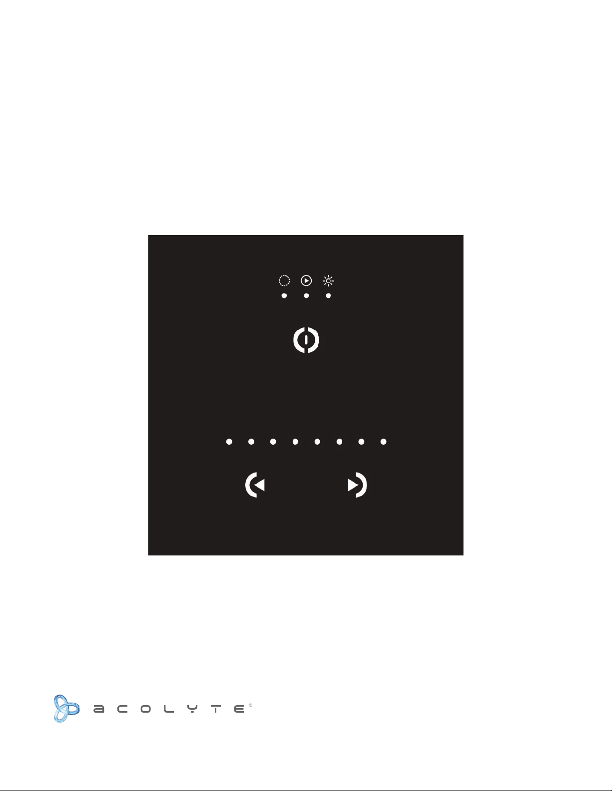
MINI WALL CONTROLLER
DMXCTRLM INSTRUCTION MANUAL
Complete Integrated LED Lighting Solutions Tech Support: 212.629.6830
Page 2
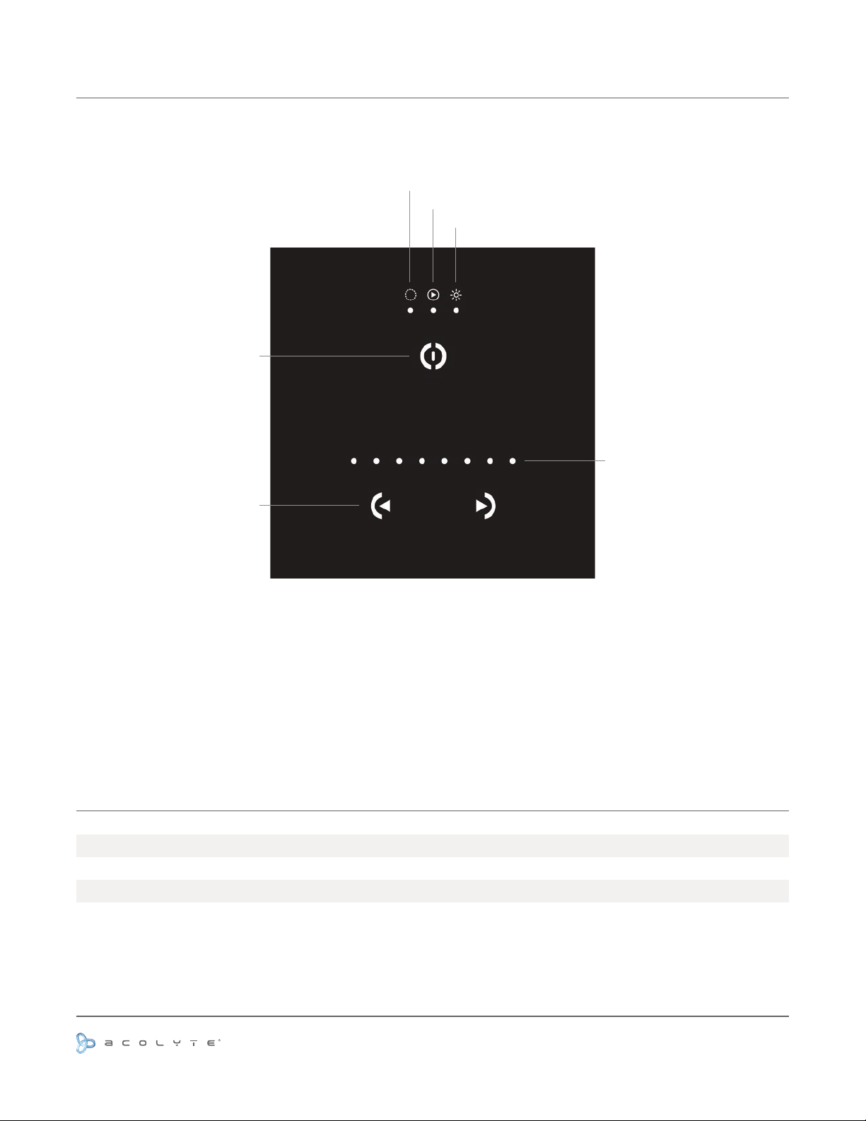
LAYOUT AND FEATURES
Power Button /
Hold to change mode
Color
Scene
Dimmer
Status Indicator
Color, scene and dimmer
DIMENSIONS
Width
Height
Depth
adjusters
3.39” / 86.0 mm
3.39” / 86.0 mm
0.39” / 10.0 mm
Use or reprinting prohibited unless explicitly approved by Acolyte Industries.
All artwork and images copyright Acolyte Industries Inc.
PAGE 1
Page 3
PRODUCT SPECS
Input power
DMX output #1
Available colors
Package contents
PC requirement
Software included
Standards
Temperature
Weight
Protection Rating
Connections
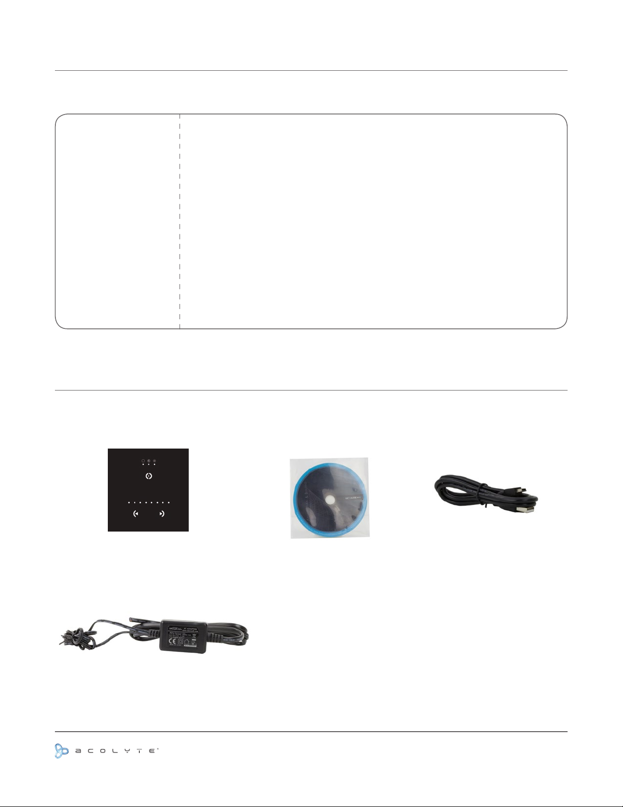
INCLUDED CONTENTS
5 VDC to 12 VDC
Up to 128 channels DMX512
Frame: black or white
Control unit, CD-ROM, USB cable, power supply
Mac OSX 10.7, 10.7, 10.8 | Windows XP/Vista/7, 32/64 bits and USB 2.0
ESA, ESA 2 (PC & Mac)
EC, EMC, ROHS, ETL, UL (some are in process)
32º F to 122º F / 0º C to 50º C
0.24 lb / 110.0 g
IP20
Power (2 pins), DMX (3 pins), Port (2 pins), Micro USB
Control Unit
9V DC Power Supply
Use or reprinting prohibited unless explicitly approved by Acolyte Industries.
CD-ROM USB Cable
PAGE 2
All artwork and images copyright Acolyte Industries Inc.
Page 4
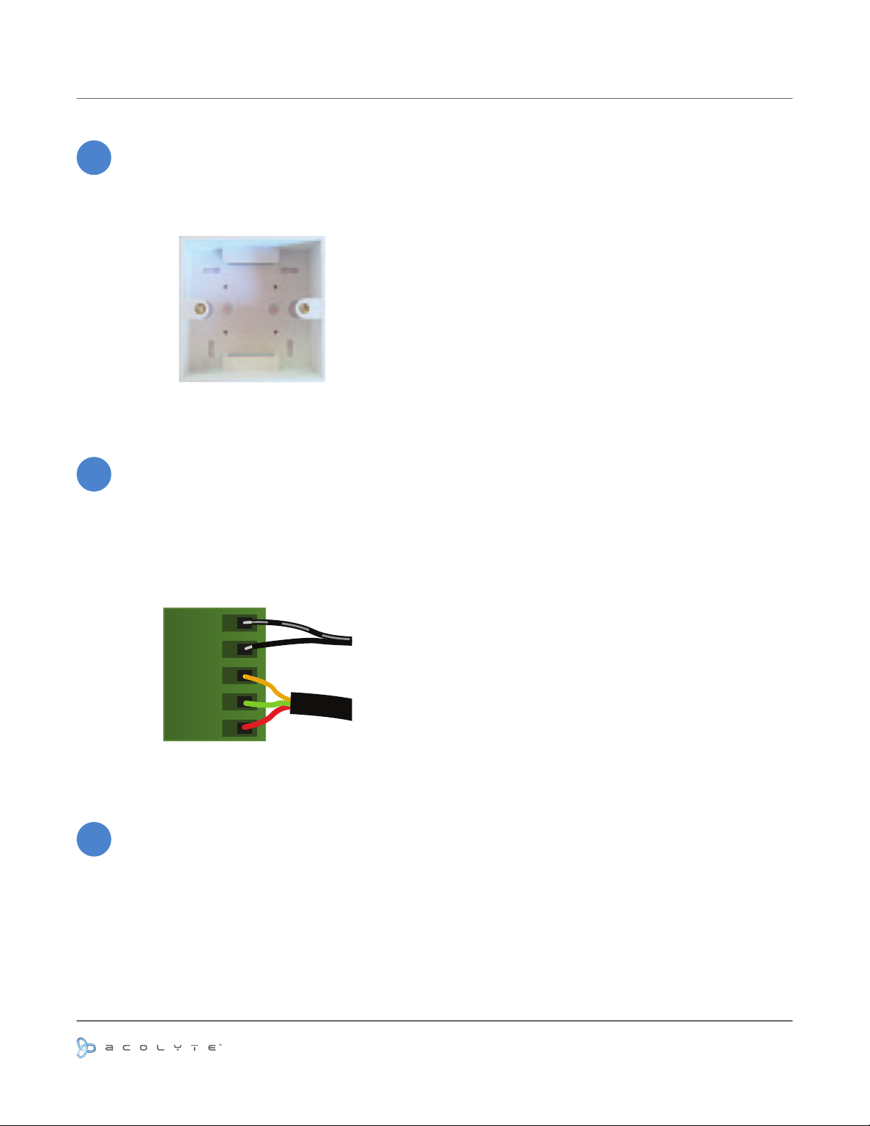
INSTALLATION
POWER
DC +
POWER
Ground
DMX
Ground
DMX -
DMX +
Mount an electrical box inside the wall.
1
The controller can be installed in any
standard 60 mm electrical gang box.
You can insert the AC/DC adapter
inside or outside the backbox.
Connect the wires.
2
DMX: Connect the DMX cable to the
external DMX interface.
Power: Connect the AC/DC adapter
Mount the back of the controller on the wall using 2 or more
3
screws.
Plug the green terminal block into the back of the front panel.
Snap the front panel onto the back and lock with a screw into
the bottom of the front panel.
Wait 30 seconds for the touch sensitivity to adjust.
Use or reprinting prohibited unless explicitly approved by Acolyte Industries.
All artwork and images copyright Acolyte Industries Inc.
PAGE 3
Page 5
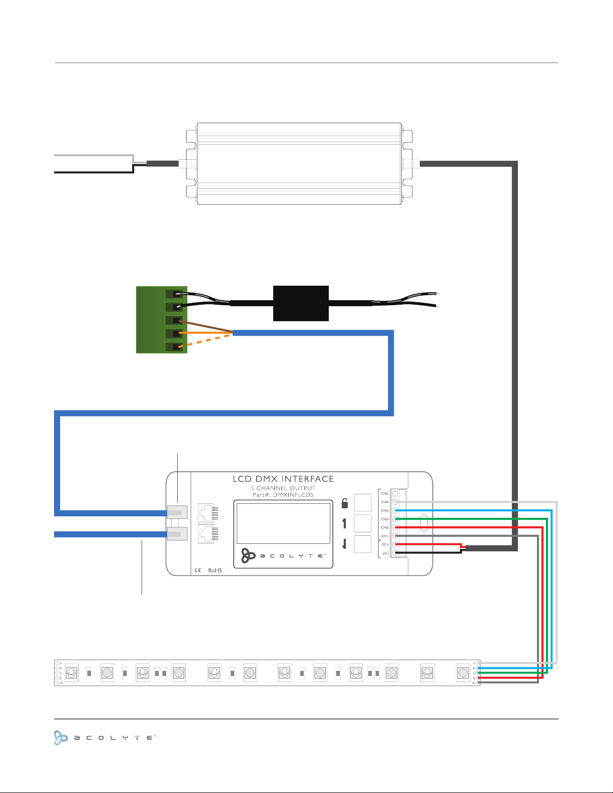
WIRING DIAGRAM
WITH DMXINFLCD5 AND RGBW/RGBA RIBBONLYTE
AC Input
12 or 24V DC Output
LED Driver
Driver to DMX Interface
BACK OF MINI WALL CONTROLLER
AC Input
Pin 8: Ground
Pin 2: Data -
Pin 1: Data +
POWER
DC+
POWER
GROUND
DMX
GROUND
DMX
DMX +
6 V DC
ADAPTER
-
12 or 24 V DC from
Cat 5 cable between DMX
controller and DMX interface
RJ45 Connector
DMX IN DMX OUT
88 11
Pin 1: Data +
Pin 2: Data Pin 8: GND
www.AcolyteLed.com
POWER IN LED OUT
INPUT: DC 12 V ~ 24 V
OUTPUT: Max 20 A
DMX out to
next interface +
20-22 gauge wire
5-conductor
181
301
181
300
300
181
301
181
470
Use or reprinting prohibited unless explicitly approved by Acolyte Industries.
All artwork and images copyright Acolyte Industries Inc.
PAGE 4
 Loading...