

Page 1
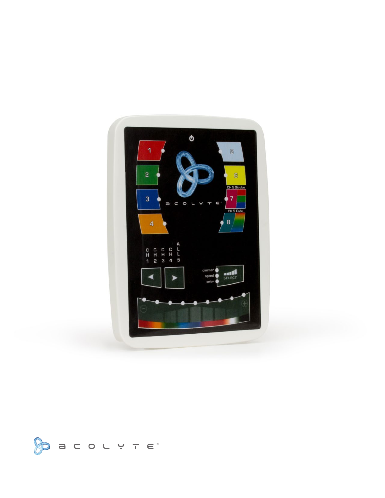
5-ZONE WALL CONTROLLER
DMXCTRL INSTRUCTION MANUAL
Complete Integrated LED Lighting Solutions Tech Support: 212.629.6830
Page 2
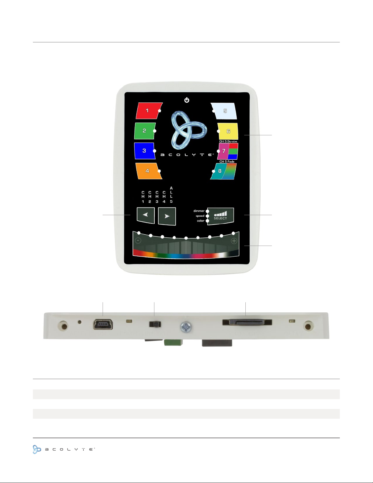
LAYOUT AND FEATURES
FRONT VIEW
Customizable preset
buttons
Customizable preset
BOTTOM VIEW
DIMENSIONS
buttons
Dimmer, Speed,
Color Control
Increase and
decrease control
values
USB USB Switch Mini SD
Width
Height
Depth
Use or reprinting prohibited unless explicitly approved by Acolyte Industries.
All artwork and images copyright Acolyte Industries Inc.
5.04” / 128.0 mm
6.61” / 168.0 mm
0.45” / 11.5 mm
PAGE 1
Page 3
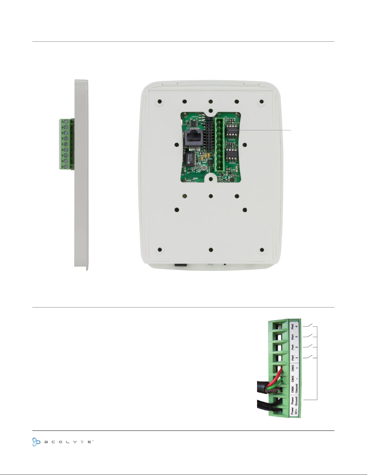
LAYOUT AND FEATURES CONTINUED
SIDE VIEW BACK VIEW
Terminal block
input
NOTE ABOUT CONNECTIONS
All connections (DMX, power, ports...) are made with the rear connectors.
The 9V DC power supply must be connected to the 2 Power pins, and the
1st DMX universe to the 3 DMX pins of the main 9-pin connector block (see
the picture below). This interface has 4 ports (1 to 4) to trigger 4 different
scenes. To use the input ports, you must create a connection between the
Ground pin and the ports (see the picture to the right).
The interface can be powered either with the external power supply or
through USB. You must move the “Power” button (next to the USB port) to
switch from USB to EXT.
It is very important to NEVER move the “USB TO EXT” switch while this
controller is connected to the computer.
Use or reprinting prohibited unless explicitly approved by Acolyte Industries.
All artwork and images copyright Acolyte Industries Inc.
PAGE 2
Page 4
PRODUCT SPECS
Input power
DMX output #1
DMX output #2
Available colors
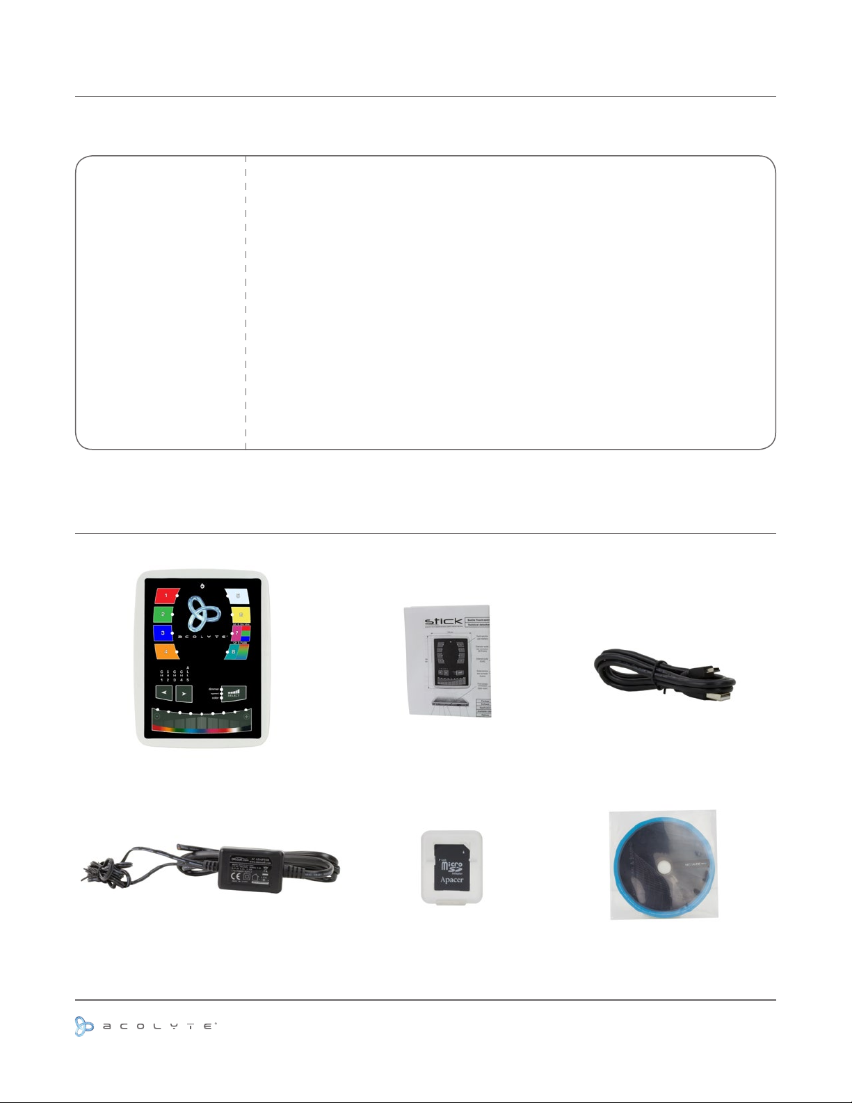
Package contents
PC requirement
Software included
Standards
Temperature
Weight
Microphone
INCLUDED CONTENTS
9 V DC, 0.65 A adapter, included
1st universe 512 channels DMX512
2nd universe 512 channels DMX512, with extension socket
Frame: black or white
Control unit, SD card, datasheet, CD-ROM, USB cable, power supply
Windows XP/Vista/7, 32/64 bits and USB 2.0
ESA, ESA PRO and ESA PRO TOOLS
EC, EMC, ROHS, ETL, UL (some are in process)
14º F to 122º F / -10º C to 50º C
0.44 lb / 199.6 g
Built-in microphone for sound to light effect
Control Unit
9V DC Power Supply
Use or reprinting prohibited unless explicitly approved by Acolyte Industries.
Datasheet
SD Card
All artwork and images copyright Acolyte Industries Inc.
USB Cable
CD-ROM
PAGE 3
Page 5

INSTALLATION
Mount an electrical box inside the wall.
1
The controller can be installed in any
standard electrical gang box. If you use
a double size box, you can insert the
power supply inside.
Connect the wires.
2
DMX: Connect the DMX cable to the
external DMX interface.
Power: Connect the included 9V DC
power supply. The cable with the white
stripe is DC+.
Mount the back of the controller on the wall using 2 or more
3
screws.
Plug the green terminal block into the back of the front panel.
Snap the front panel onto the back and lock with a screw into
the bottom of the front panel.
Use or reprinting prohibited unless explicitly approved by Acolyte Industries.
All artwork and images copyright Acolyte Industries Inc.
PAGE 4
Page 6
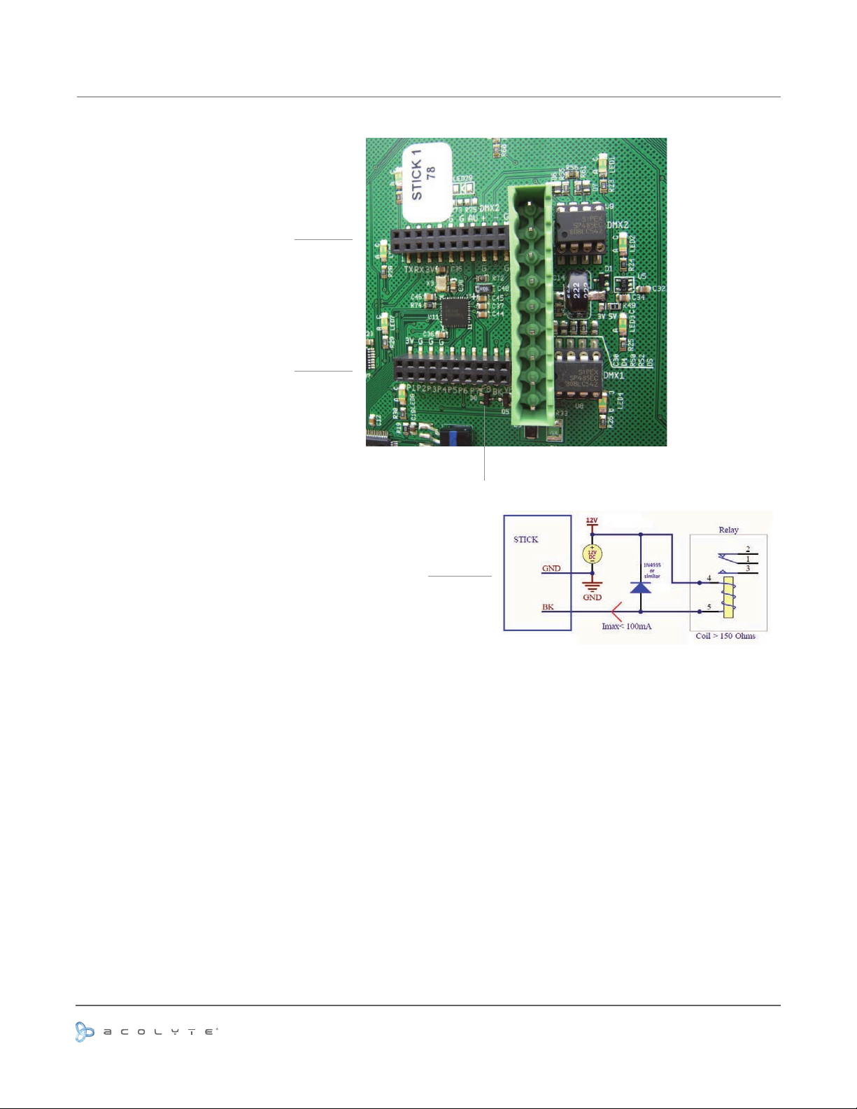
EXTENSION SOCKET REAR CONNECTORS (OPTIONAL)
RS232 Connections: Make a 3-pin cable
Use TX, RX and G (GND)
Set the RS232 parameters to: 9600 bds
8 bits, no parity, 2 stop bits
Ports 1-8: Use ports 1 to 8 to make contacts
between G (GND) and P1...P8
Blackout: Connect a relay
Use the 2 pins BK and G (GND)
Example of relay
RS232 Triggering
To play a scene, send 3 bytes (HEX mode): 1 x 255 (x = scene number)
To stop a scene, send 3 bytes (HEX mode): 2 x 255 (x = scene number)
To pause a scene, send 3 bytes (HEX mode): 3 x 255 (x = scene number)
To release a scene, send 3 bytes (HEX mode): 4 x 255 (x = scene number)
To reset a scene, send 3 bytes (HEX mode): 5 x 255 (x = scene number)
Note: the scene number (x) can be from 1 to 40. For instance, 11 means Page B, Scene #3
Troubleshooting
If the on/off and all 8 LED buttons are ashing, the SD card is missing or damaged
If all 8 LED buttons are ashing, the SD card is empty
If all LEDs are ashing, there is a problem with the rmware
Use or reprinting prohibited unless explicitly approved by Acolyte Industries.
All artwork and images copyright Acolyte Industries Inc.
PAGE 5
Page 7
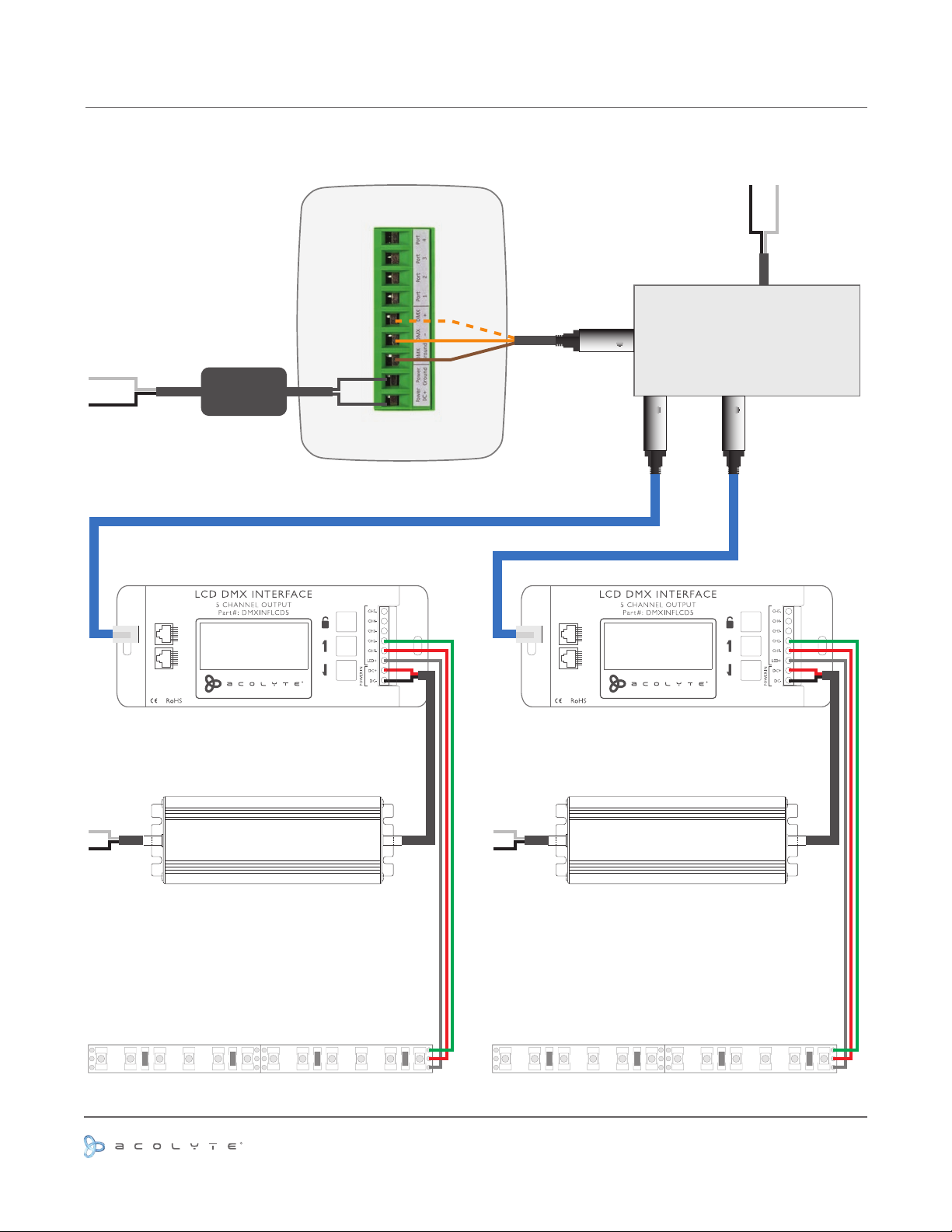
WIRING DIAGRAM
WITH DMXOS AND DMXINFLCD5
AC Input
9V DC
POWER SUPPLY
Back of DMXCTRL
AC Input
3-pin XLR
DMX 512 OPTI-SPLITTER
3-pin XLR 3-pin XLR
DMX IN DMX OUT
Pin 1: Data+
Pin 2: Data Pin 8: GND
8 18 1
www.AcolyteLed.com
LED OUT
INPUT: DC 12 V ~ 24 V
OUTPUT: Max 20 A
AC Input AC Input
12 or 24V DC Output
LED Driver
12 or 24 V DC to LEDs 12 or 24 V DC to LEDs
680
680
680
680
DMX IN DMX OUT
680
8 18 1
Pin 1: Data+
Pin 2: Data Pin 8: GND
www.AcolyteLed.com
12 or 24V DC Output
LED Driver
680
680
LED OUT
INPUT: DC 12 V ~ 24 V
OUTPUT: Max 20 A
680
Use or reprinting prohibited unless explicitly approved by Acolyte Industries.
All artwork and images copyright Acolyte Industries Inc.
PAGE 6
Page 8
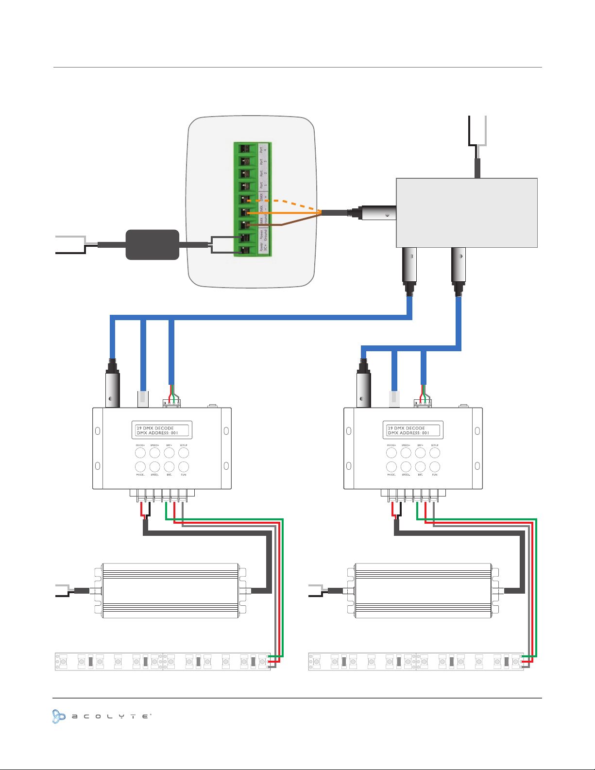
WIRING DIAGRAM
WITH DMXOS AND DMXINFADV
AC Input
9V DC
POWER SUPPLY
Back of DMXCTRL
XLR RJ45 Wire
AC Input
3-pin XLR
DMX 512 OPTI-SPLITTER
3-pin XLR 3-pin XLR
XLR RJ45 Wire
AC Input
or or
12 or 24V DC Output
LED Driver
12 or 24 V DC to LEDs 12 or 24 V DC to LEDs
or or
AC Input
12 or 24V DC Output
LED Driver
680
680
680
680
680
680
680
680
PAGE 7
Use or reprinting prohibited unless explicitly approved by Acolyte Industries.
All artwork and images copyright Acolyte Industries Inc.
Page 9
USING ESA PRO SOFTWARE TO PROGRAM YOUR CONTROLLER
CREATING A NEW SHOW
Adding Your DMX Devices
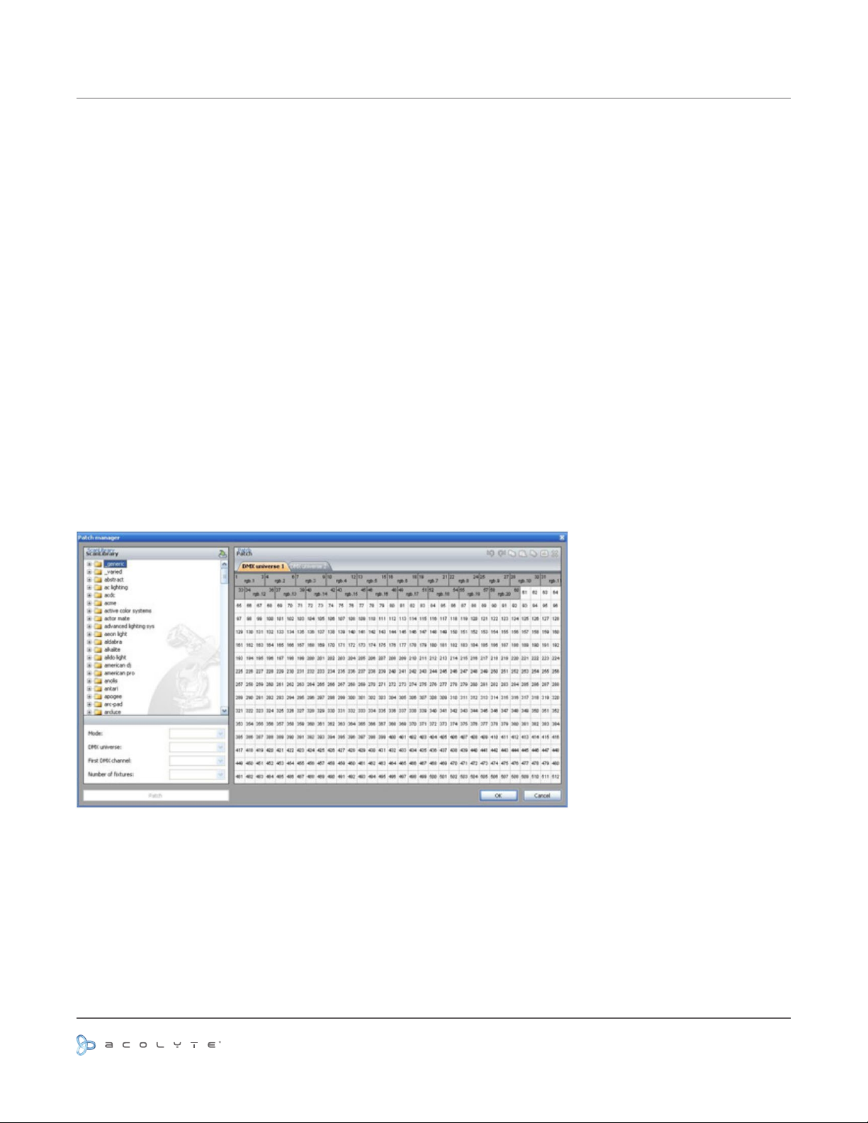
The Fixtures Patch
The editor screen is the place where you will have to patch your xtures. This is the rst thing to do to create
your show.
Click on the “Add xture(s)” button from the toolbar to open the “Patch manager” window.
Here is the procedure to add new xtures:
- select the prole from the left-side manufacturer list
- select the DMX universe
- enter the rst DMX channel (address of the 1st xture)
- enter the number of devices
- validate by clicking on the “patch” button
Note: There is a another method to add a xture. You can directly drag and drop the prole to the grid. Then,
you can right-click on the xture and select “duplicate” from the menu to add more devices (using the same
prole).
Once the patch is ready, you will need to create and setup the zones (areas). The next section shows how to
proceed.
PAGE 8
Use or reprinting prohibited unless explicitly approved by Acolyte Industries.
All artwork and images copyright Acolyte Industries Inc.
Page 10
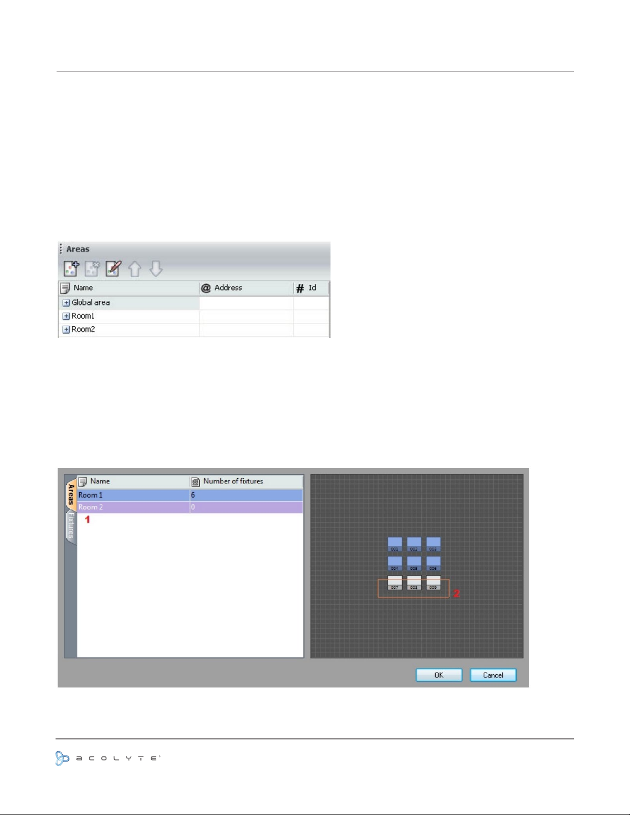
CREATING A NEW SHOW
THE ZONES PATCH
You can then decide to setup several zones (areas). Zones are very important for a multi-room installation in
order to be able to play a different scene for each zone.
All xtures are assigned to the “global area” by default. This zone can play a sequence for all xtures and
cannot be removed.
As an example, we can create 2 zones (Room 1 and Room 2). From the “Areas” window, click on the left-side
button “+” to add a new zone. Click on the “Rename” button from the toolbar to call it “Room 1” and repeat the
operation for the second zone.
You will then have to click on the “Areas patch” button from the toolbar to assign your xtures. Remember
they are all assigned to the “Global area” and cannot be removed from it.
You can assign your DMX devices to an area within the Areas tab or the Fixtures tab.
Using the Areas tab, simply select the area on the left (1) then select the devices you wish to include within the
area (2).
Use or reprinting prohibited unless explicitly approved by Acolyte Industries.
All artwork and images copyright Acolyte Industries Inc.
PAGE 9
Page 11
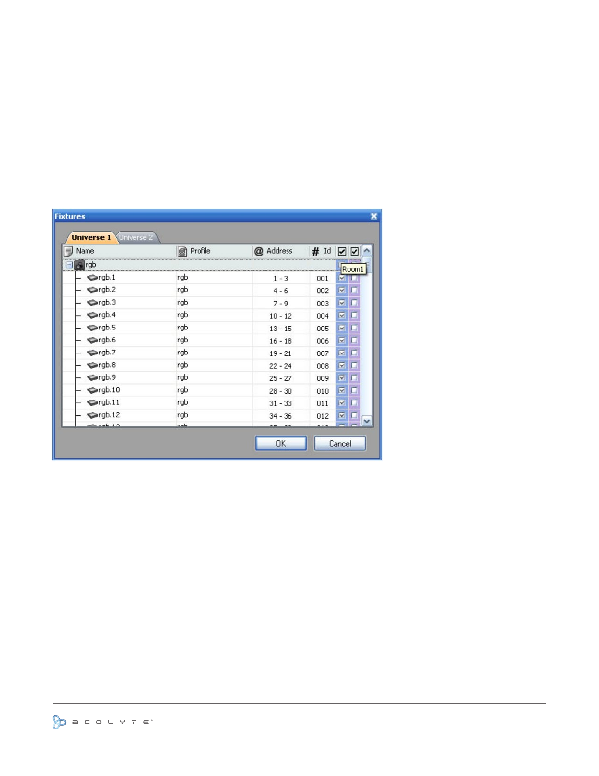
CREATING A NEW SHOW
THE ZONES PATCH
The window (shown below) shows a list of all the DMX devices in the different universes. To assign a DMX
device to a zone, you must select the corresponding checkbox on the right side of the list. There is a column
for each zone and you can check their name by moving your mouse on the column header, as shown below.
Note: A DMX device cannot be assigned to several zones (areas). Assigning a xture to a zone will remove its
previous assignment.
Use or reprinting prohibited unless explicitly approved by Acolyte Industries.
All artwork and images copyright Acolyte Industries Inc.
PAGE 10
Page 12
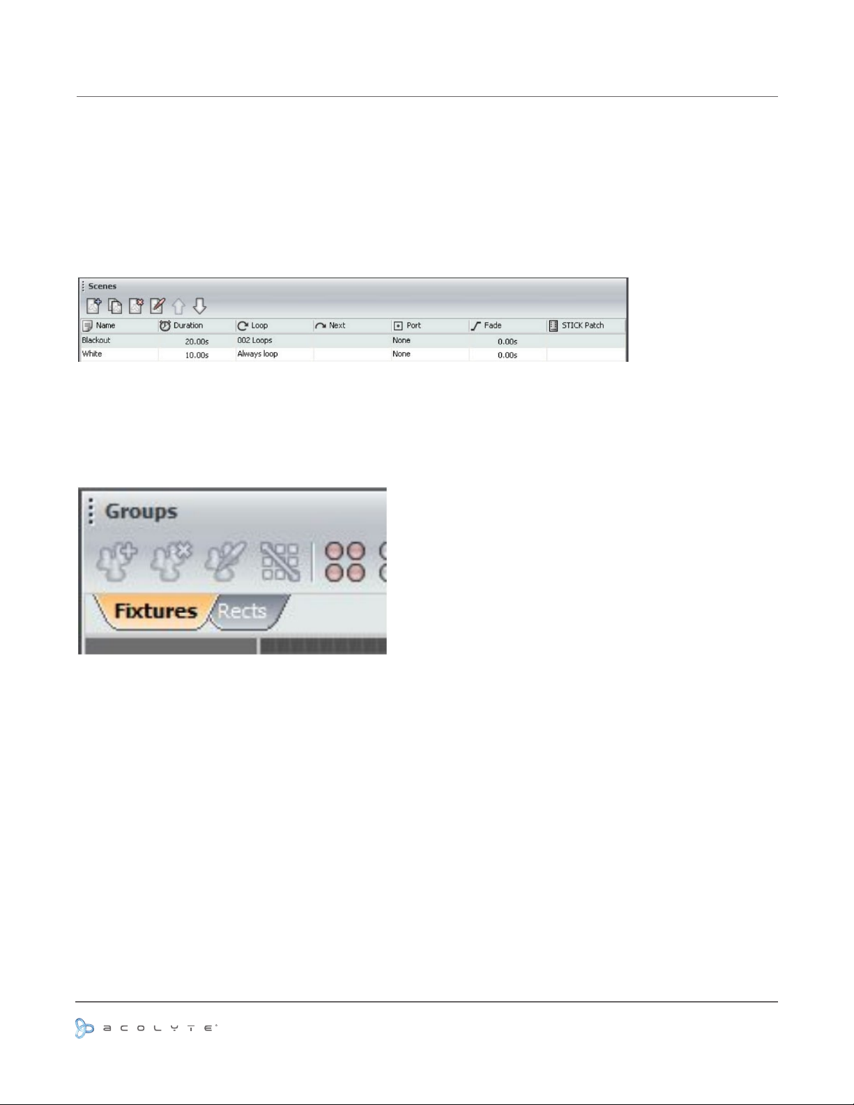
CREATING YOUR SCENES
FIXTURES SELECTION
It is important to select a zone before creating a new scene. There is a list of scenes for every zone (area).
Select a zone from the “Areas” window to display the attached scenes in the “Scenes” window.
Click on the “+” button (left side of the “Scenes” window) to create a new scene. A scene is made with the
timelines but the rst thing to do is to select the xtures you want to use from the “Groups” window.
Selecting the xtures
It is not possible to edit a scene without any xture selected from the “Groups” window. Two modes are
available: Fixtures and Rects.
Use or reprinting prohibited unless explicitly approved by Acolyte Industries.
All artwork and images copyright Acolyte Industries Inc.
PAGE 11
Page 13

CREATING YOUR SCENES
SETTING UP THE POSITIONS
It is important to setup the positions of your xtures in order to visualize them correctly. It is often easier to
build your sequences if you have an idea of your xtures actual positions.
To alter to position of a xture, simply select the xture and drag to the desired location within the group
window. Use the line, circle, square or matrix icons on the group toolbar to quickly arrange your xtures into a
shape.
This section explains how to set up a matrix of xtures, such as a colored wall matrix or an LED danceoor. In
the example below, we will be using the “Matrix” tool to set up a 10x10 matrix.
Procedure to create a 10x10 matrix:
- Select all xtures using your mouse or the “Select all” button from the toolbar
- Click on the “Matrix” button from the toolbar
- Enter 10 x 10 in the Matrix window
- Validate by clicking on “OK”
Imagine your xtures are not individual RGB devices but 2 x 2 matrix of 4 RGB devices (12 DMX addresses),
you can setup an advanced position for your matrix:
- Select all xtures using your mouse or the “Select all” button from the toolbar
- Click on the “Matrix” button from the toolbar
- Enter 10 x 10 in the Matrix window
- Click on Advanced positionning
- Press the “Settings” button from the “Matrix patch” window
- From the “Advanced positioning” window, select 2 x 2 for the “Primary matrix” and press “OK”
Use or reprinting prohibited unless explicitly approved by Acolyte Industries.
All artwork and images copyright Acolyte Industries Inc.
PAGE 12
Page 14
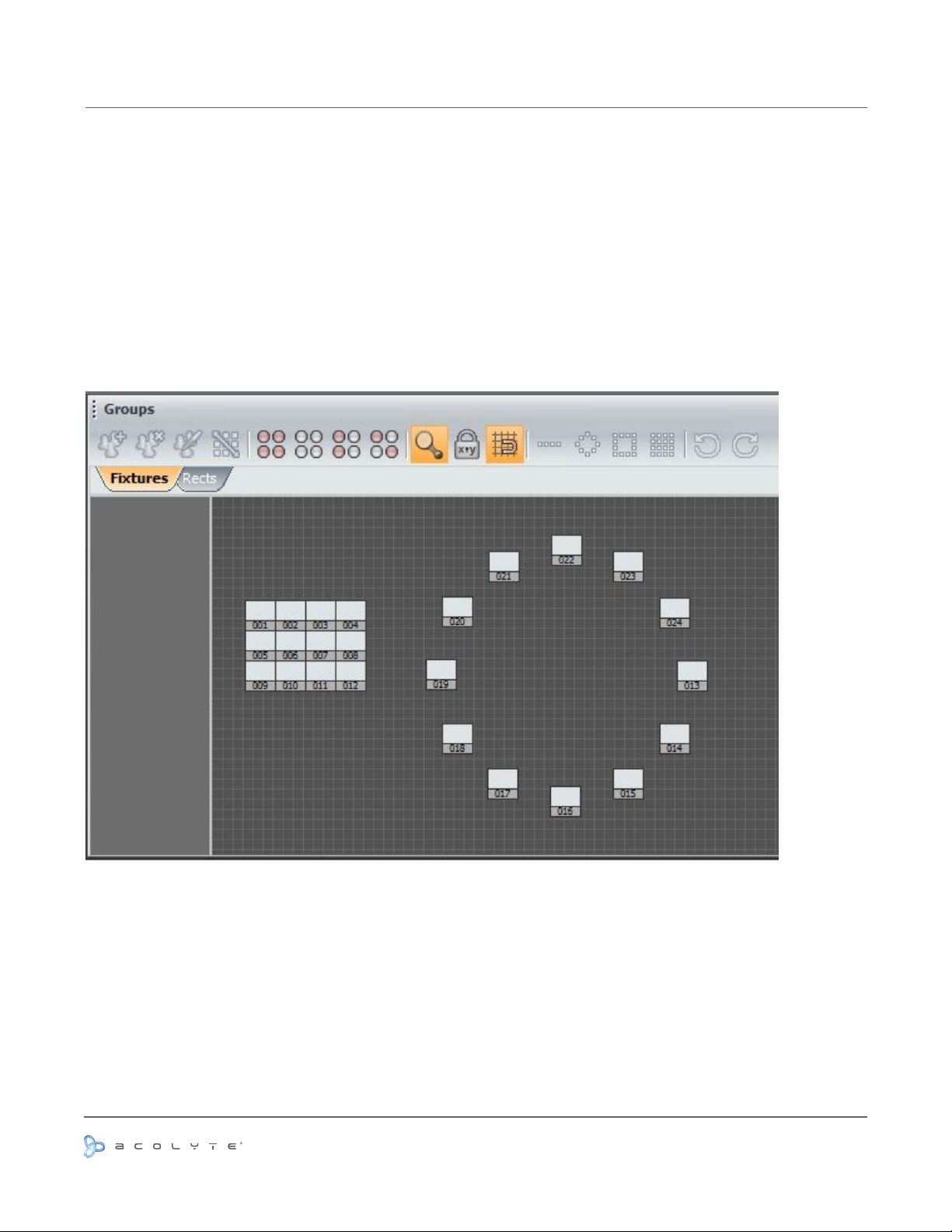
CREATING YOUR SCENES
SELECTING THE FIXTURES
Every xture is represented by a little square. The selection is made with the mouse. You can use the CTRL
key for a multi-selection or the various options from the toolbar (select ALL, HALF, INVERT...)
It is also possible to create groups of xtures. Follow this procedure to create a new one:
- Select the xture to be added to the group
- Click on the “Add” button (left side of the toolbar)
A group can be deleted or renamed using the buttons of the toolbar.
Use or reprinting prohibited unless explicitly approved by Acolyte Industries.
All artwork and images copyright Acolyte Industries Inc.
PAGE 13
Page 15
CREATING YOUR SCENES
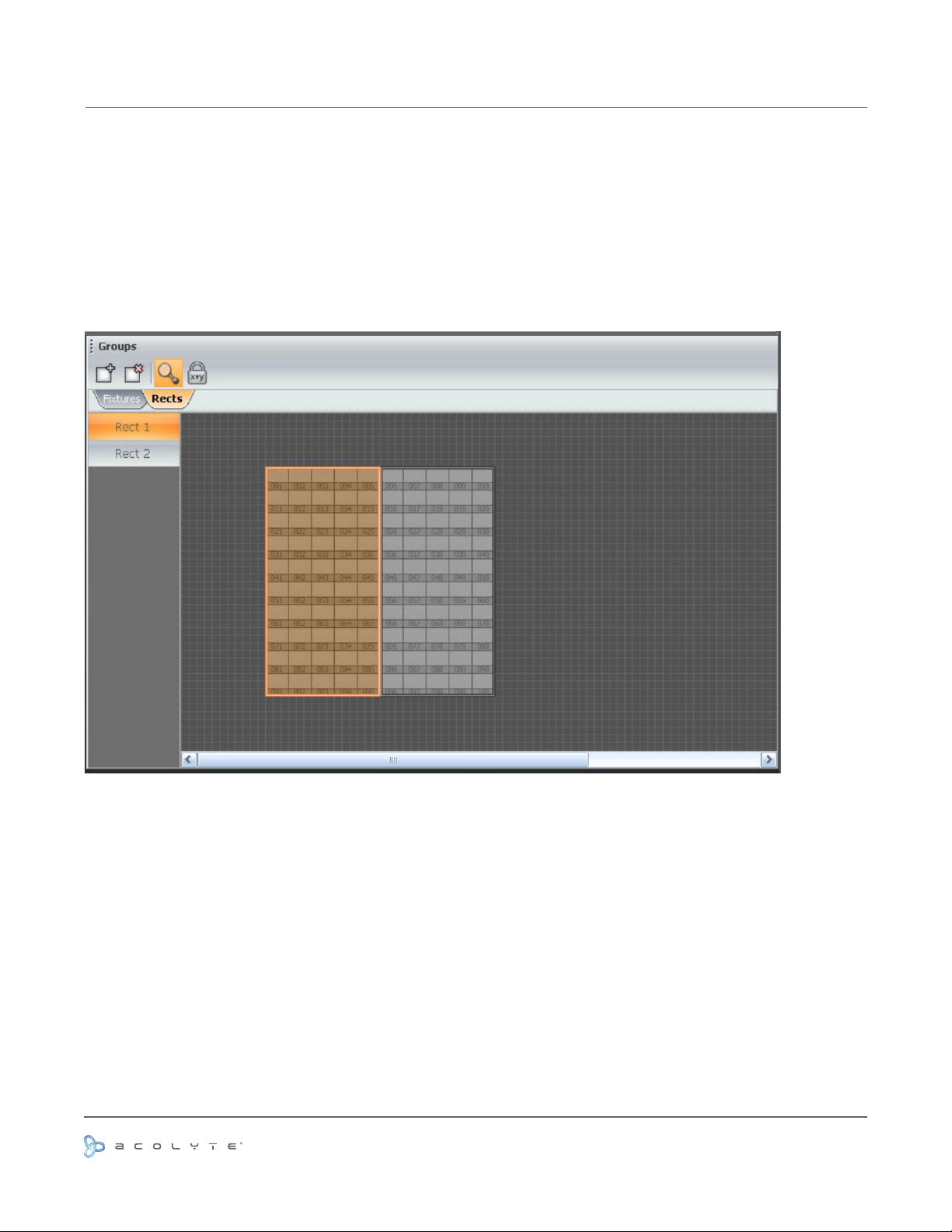
THE RECTS MODE
A rect is a virtual zone where a sequence can be played. You can for instance, play several sequences on the
same LED screen at different positions using several rects.
From the Rects window, click on the “Add rect” button to create a new rect, this will highlight the button and
activate the rect drawing function. Just click on the grid and hold the button to draw a new rect. It is possible
to modify its size and position with the mouse.
Created rects are listed on the left of the window (Rect1, Rect2...) and can be called at any time. Do not forget
that a rect is the property of a specied zone (area).
PAGE 14
Use or reprinting prohibited unless explicitly approved by Acolyte Industries.
All artwork and images copyright Acolyte Industries Inc.
Page 16
CREATING YOUR SCENES
SCENES CONSTRUCTION
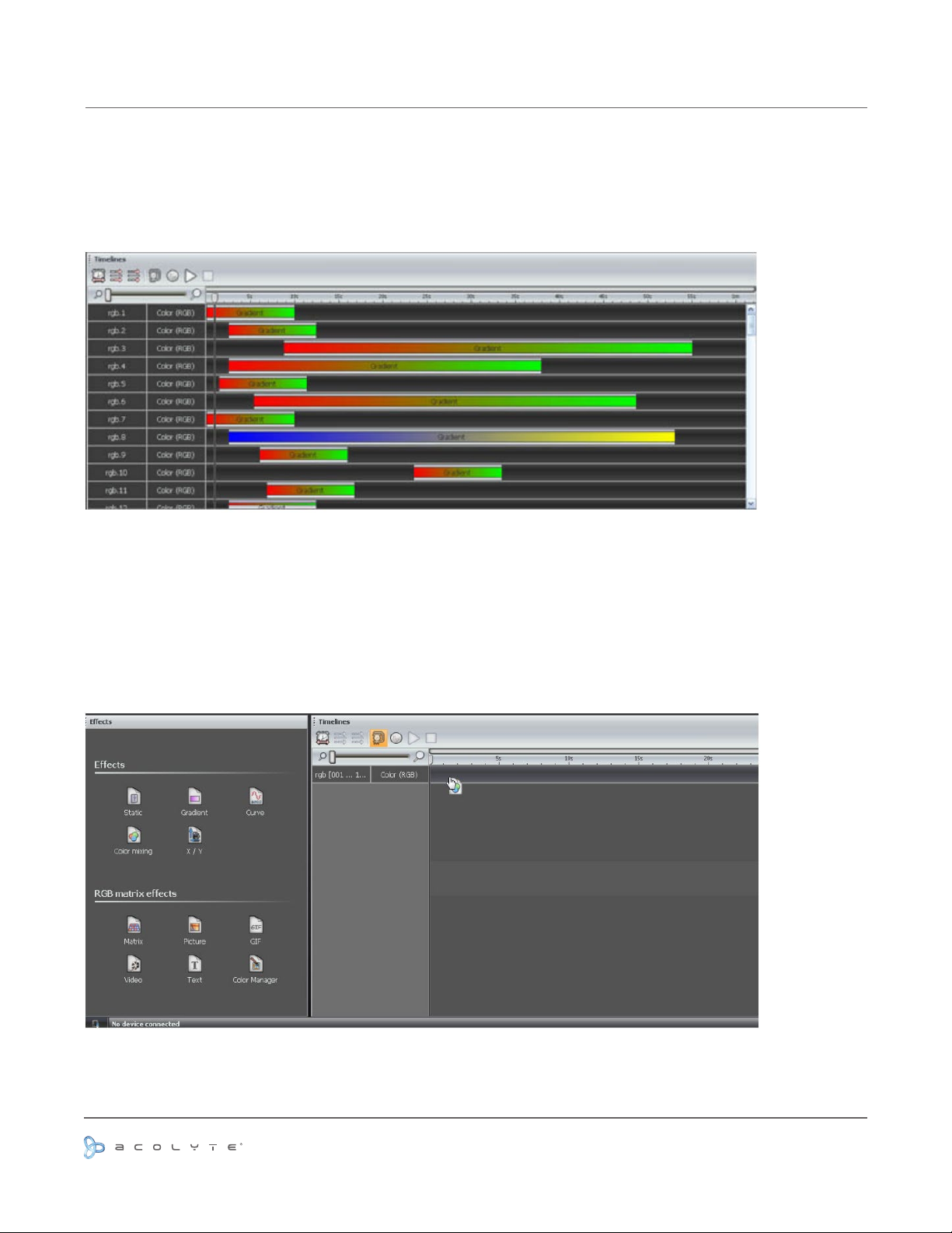
A scene is built with a timeline. There is a line for every single xture selected or for a group of xtures.
Several options are available (link, compress...).
Adding an effect to the timelines
An effect can be added to the timeline with a simple drag and drop.
An effect can be added to a single xture or a group of xtures. Click on the desired effect from the “Effects”
window and drag it to the timeline as shown below. Once the mouse button is released, the software will open
the effect options window.
Use or reprinting prohibited unless explicitly approved by Acolyte Industries.
All artwork and images copyright Acolyte Industries Inc.
PAGE 15
Page 17
THE EFFECTS
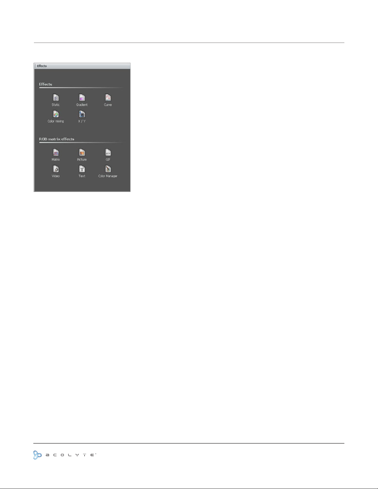
Once the selection is made, you must select an effect from the “Effects” window and drag it to the timeline.
It is not possible to drag an effect if there are no xtures selected. Here is a brief description of the available
effects:
Static level:
This effect enables setup of a static level for the selected xture. Once the effect is assigned to
the timeline the following window is opened (if the effect is assigned to a color channel).
3 modes are available to set up a color:
- color picker
- preset colors (red, green, cyan...)
- manual selection of the RGB values
Note: it is possible to set the duration of the effect by clicking on the left-side icon from the toolbar.
Gradient:
This effect enables creating a fade between DMX values (color, positions...). In the case of a color
gradient, it is possible to add more points. You must double click on the gradient zone to add a new step.
Then, you can select it and change the color or its position within the gradient.
Phasing: It is possible to add a delay between your xtures using the “Phasing” option. It is very useful to
create a rainbow effect for instance.
Do not forget to use the “Play” button to preview your effect. It is possible to edit an effect by double clicking
on it from the timeline.
Curve (advanced):
This tool allows you to have more control over the individual channels of your xtures
and is extremely useful with LEDs. The rst thing to do is to select the channel you want to work with (Red,
Green...) and then select a waveform from the list (Sinus, Square...).
Several options are available like Amplitude and Offset. We advise you to play with these options to see how
they work with your xtures.
Use or reprinting prohibited unless explicitly approved by Acolyte Industries.
All artwork and images copyright Acolyte Industries Inc.
PAGE 16
Page 18

THE EFFECTS
Phasing: It is possible to add a delay between your xtures using the “Phasing” option. It is very useful for
creating a rainbow effect, for instance.
You must click on the “Fixtures order” button (3rd button from the left in the toolbar) to set up a direction
for your phasing. The following window is opened and you can use the UP and DOWN buttons to change the
order or record a completely new direction using the “rec” button.
Color:
The color-mixing tool is the easiest way to create complex color effects. First, select an effect from the
drop-down menu and then modify the different options.
You can vary the size, speed and duration fo the effect as well as change the colors used by clicking the pallet
icon. You can also change the number of colors used.
It is possible to change the order and direction of the effect by clicking on the “Fixtures order” button from the
toolbar.
Pan/Tilt:
Matrix Effect:
drag this kind of effect into the regular xtures selection.
Once the matrix effect has been selected and dragged to the timeline, a window is opened and you will have to
select the type of effect (square, circle...).
Several options are available: number of colors, size and speed. It is possible to adjust these settings with the
corresponding rotary buttons. Once the number of colors has been changed, you can select the colors from
the color picker.
Picture:
will have to select a picture (BMP, JPG or PNG) le to be displayed on the matrix. This can only be used with
Rects. It is not possible to drag this effect to a regular xtures selection.
It is important to select a picture with the correct dimensions. It is not possible to display a 100x100 picture on
a 5x5 matrix, for example.
GIF:
to drag this effect to a regular xtures selection. Once the GIF effect has been selected and dragged to the
timeline, a window is opened and you will have to select a GIF le to be displayed on the matrix. Then, press
the playback button to visualize the animation.
It is important to select a picture with the correct dimensions. It is not possible to display a 100x100 picture on
a 5x5 matrix, for example.
Video:
Some compression formats cannot be read. This can only be used with Rects. It is not possible to drag this
effect to a regular xtures selection.
Enables you to assign a preset effect (square, circle...) to the selected xtures with moving channels.
It is important to know that matrix effects can only be used with Rects. It is not possible to
Once the Picture effect has been selected and dragged to the timeline, a window is opened and you
An animated GIF le can be displayed on the matrix. This can only be used with Rects. It is not possible
A video can be displayed on the matrix. The software is able to play .avi les if encoded correctly.
Once the video effect has been selected and dragged to the timeline, a window is opened and you will have to
select a video le to be displayed on the matrix. Then, press the playback button to visualize it.
It is important to select a picture with the correct dimensions. It is not possible to display a 100x100 picture on
a 5x5 matrix, for example.
Text:
Enables you to write a text (static or dynamic) on the selected matrix.
PAGE 17
Use or reprinting prohibited unless explicitly approved by Acolyte Industries.
All artwork and images copyright Acolyte Industries Inc.
Page 19
THE EFFECTS
COLOR MANAGER
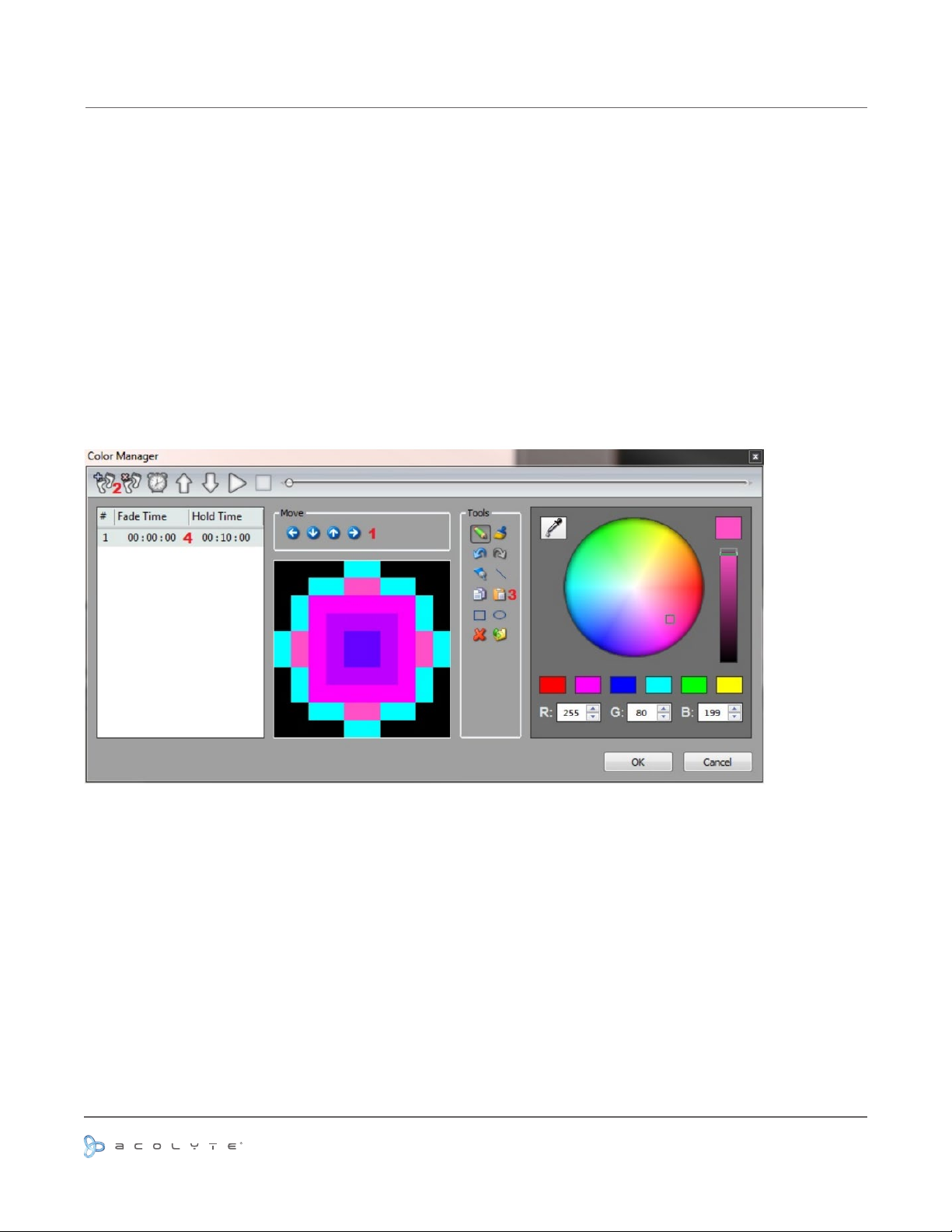
Perhaps you have used all of the effects and combined them in every way possible, but you are still looking for
something different, perhaps you want to create your own effect from scratch. The color manager allows you
to do precisely this.
Draw onto a matrix by selecting a color from the color wheel and clicking the pencil tool. The color manager
tool works in a similar way to your standard painting software package, with the ability to ll, draw lines, draw
squares and insert images.
- Move your image around the matrix here (1).
- Once you are happy with the image, click here (2) to create a new step.
When you create a new step, the previous step is copied. Other steps can be copied and pasted here (3). The
fade and wait time between each step can be changed by double clicking here (4).
Use or reprinting prohibited unless explicitly approved by Acolyte Industries.
All artwork and images copyright Acolyte Industries Inc.
PAGE 18
Page 20
THE EFFECTS
RECTS MODE
If you are not familiar with “RECTS”, please refer to the Rects Mode topic.
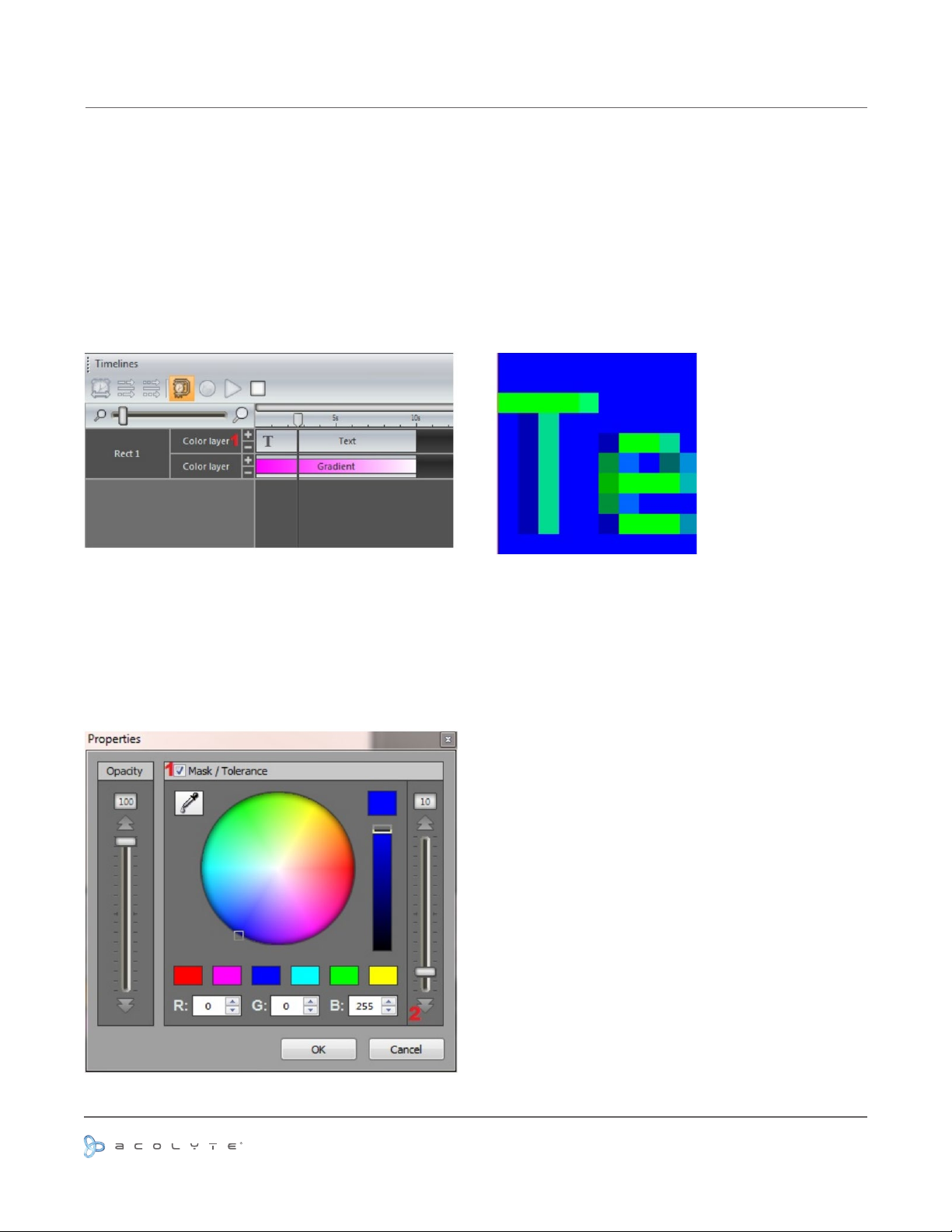
When creating effects on a rect timeline, it is possible to add several layers and drag different effects onto
each layer.
Click here to add or remove a layer (1)
In the example below, there is a gradient layer with an overlaying text layer. The text is currently blocking the
effect. Colors can be made transparent by right clicking the text layer and selecting properties.
- Click here (1) to enable masking
- Select the color you wish to mask (in the example below it is the text background color, blue)
- Adjust the tolerance here (2)
- The opacity of the layer can also be changed
Use or reprinting prohibited unless explicitly approved by Acolyte Industries.
All artwork and images copyright Acolyte Industries Inc.
PAGE 19
Page 21
THE EFFECTS
RGBW OPTIONS
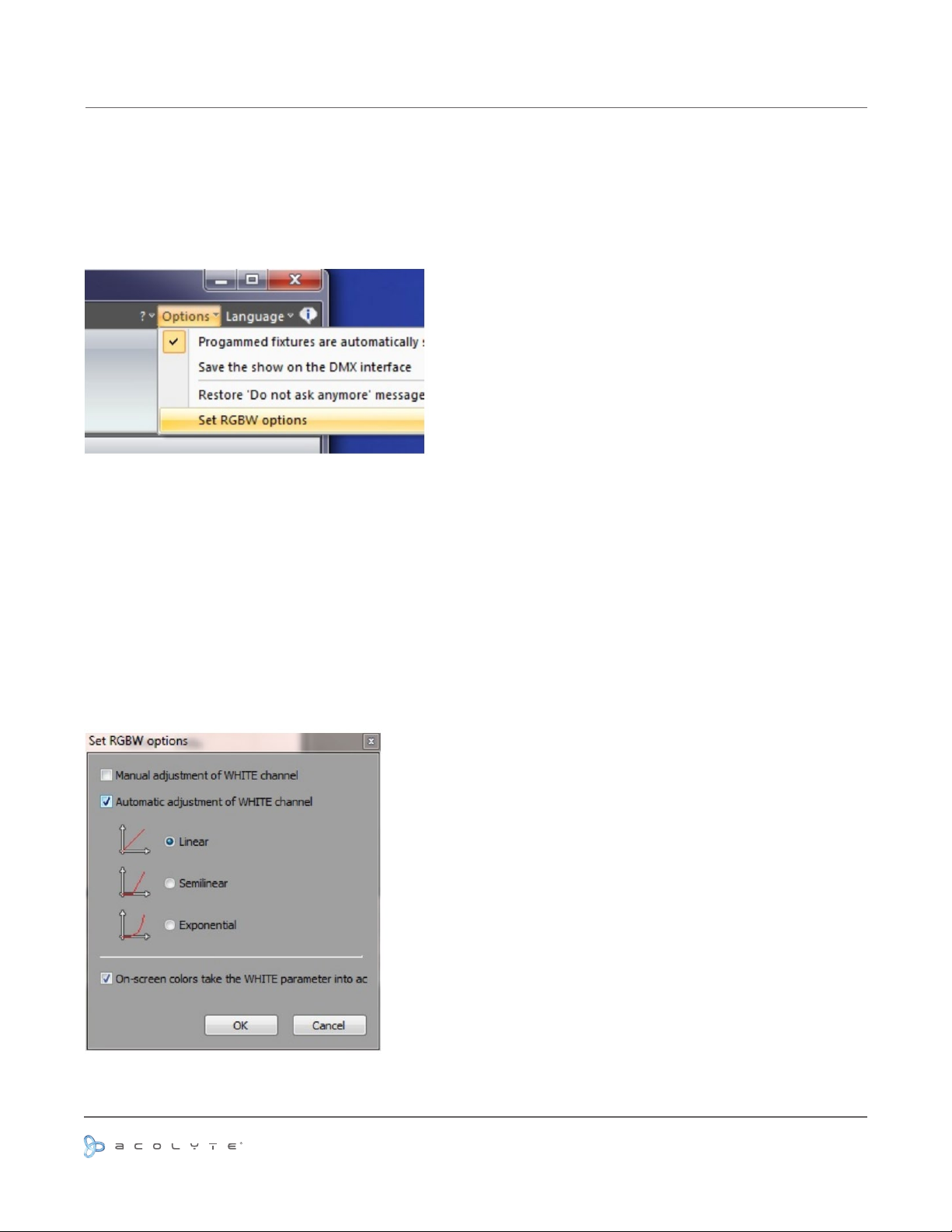
ESA Pro automaticlly calculates the RGB or RGBW values required to produce a specic color. However,
certain xtures calculate the RGBW color slightly differently. We can edit the way ESA Pro calculates the
values from the options menu.
By default, the automatic adjustment of the white channel is linear.
LINEAR: If all the Red, Green, and Blue channels are lit to 30%, this 30% will be added by the white channel
SEMI-LINEAR: The white channel will stay at 0 unless there is ateast 50% of each color
EXPONENTIAL: The white channel will accellerate as the RGB values are raised. eg. If the RGB values are at
50%, the white fader is only at 5%. At 75%, the white fader is at 22%. Then in the last 25%, the white fader
jumps up to 100%
You can also choose to have manual control of the white color fader if there is a specic color tone you wish to
produce from your xture
Use or reprinting prohibited unless explicitly approved by Acolyte Industries.
All artwork and images copyright Acolyte Industries Inc.
PAGE 20
Page 22
PLAYING YOUR SCENES IN LIVE MODE
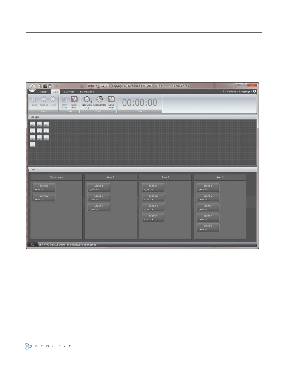
The Live tab allows you to test your scenes.
Click here (1) to view your xtures in 3D.
Use or reprinting prohibited unless explicitly approved by Acolyte Industries.
All artwork and images copyright Acolyte Industries Inc.
PAGE 21
Page 23
CALENDAR
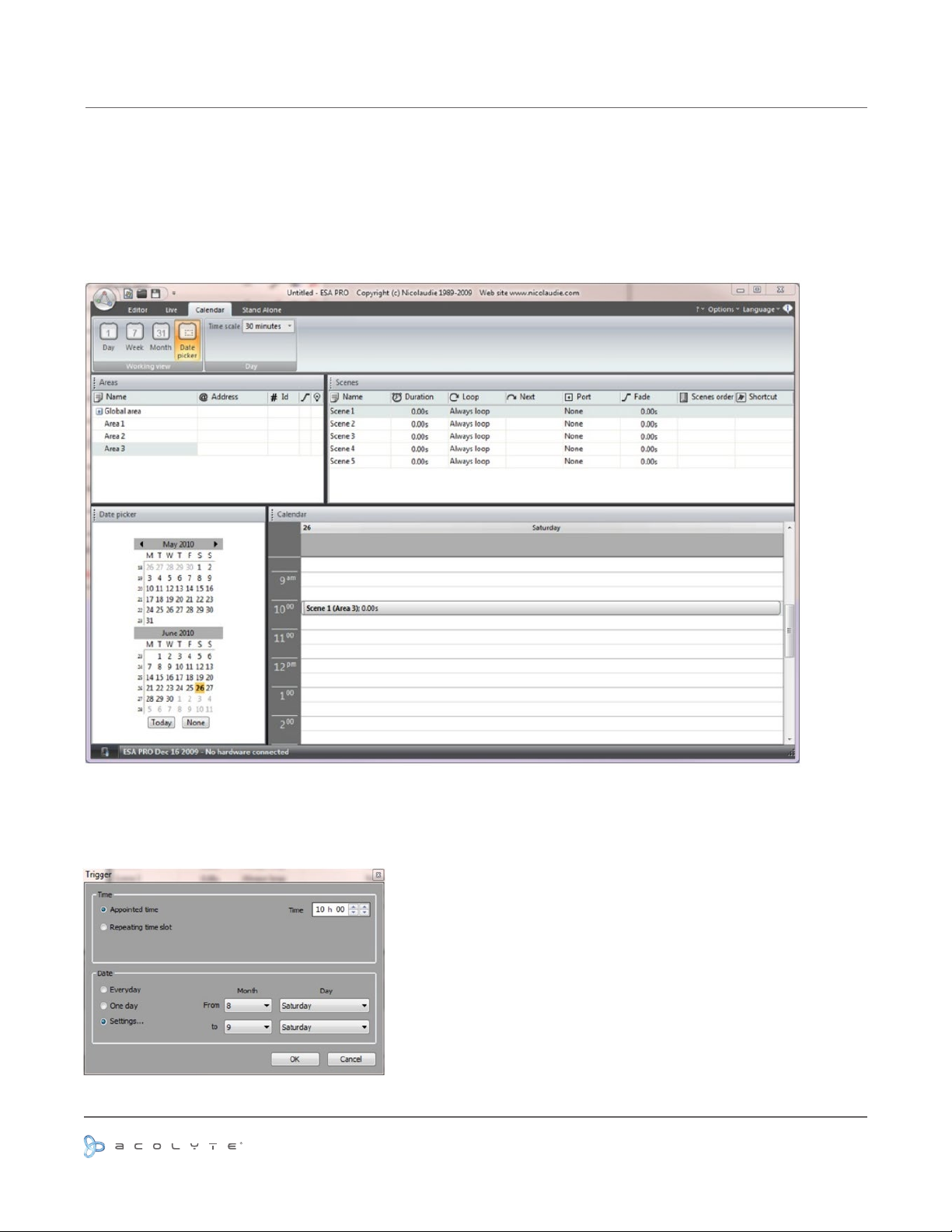
Your controller contains an internal clock and calendar. This allows you to trigger your scenes by date and
time.
Simply drag your scenes onto the calendar. The example below will trigger scene 1 at 10am on the 26th June.
Double click a trigger to edit. Re-occuring events can be set here. In the example below, our scene is set to be
triggered every saturday in August.
PAGE 22
Use or reprinting prohibited unless explicitly approved by Acolyte Industries.
All artwork and images copyright Acolyte Industries Inc.
Page 24
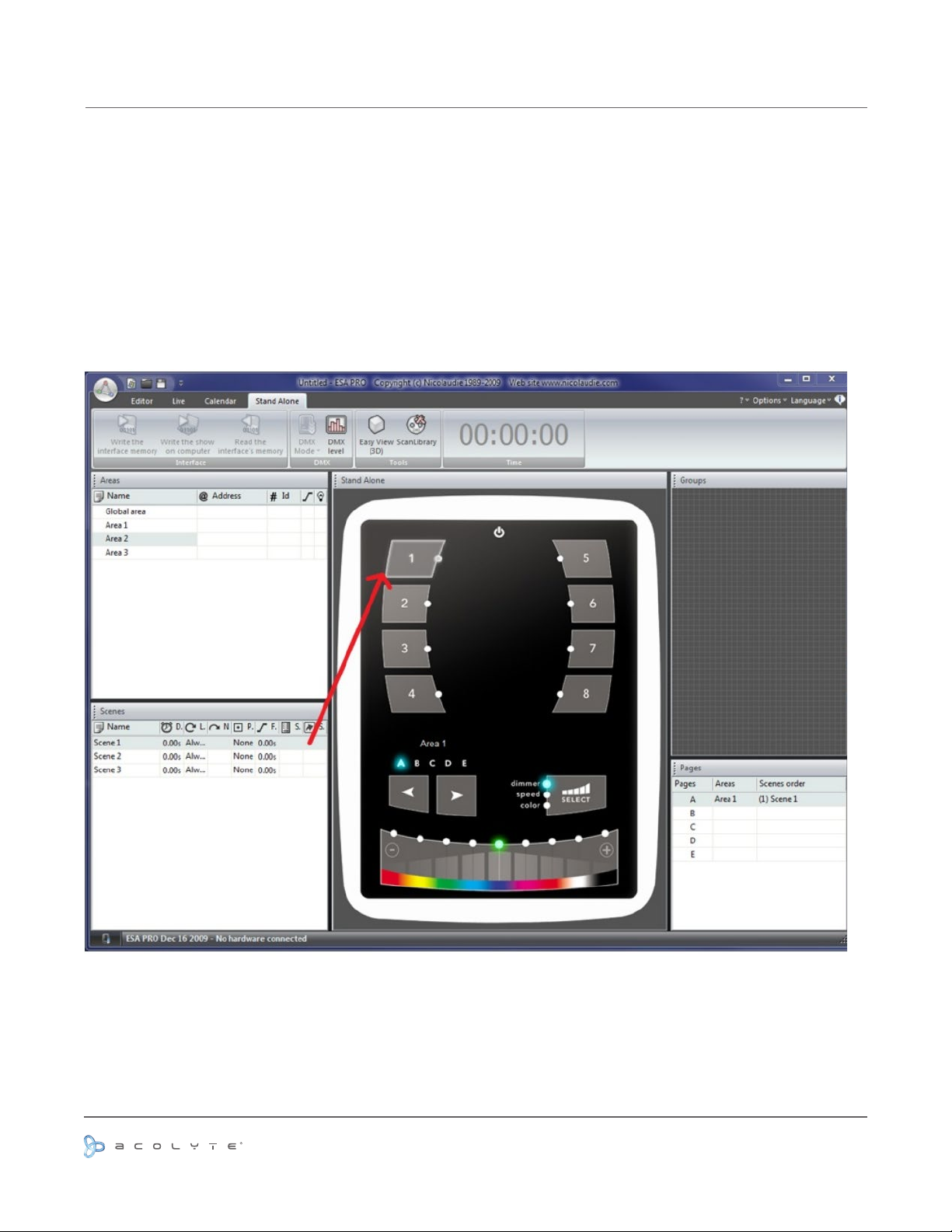
WRITING THE STANDALONE MEMORY
Adding your programming to the controller is as simple as dragging and dropping.
- select the area you wish to use
- drag the scene from the scenes panel and onto a controller scene or one of the SLESA memory blocks
To copy all scenes within a page at one, right click the interface image and select “Assign All Scenes”.
Note: Only scenes dragged to the interface will be written. This includes scenes with calendar and port triggers.
Use or reprinting prohibited unless explicitly approved by Acolyte Industries.
All artwork and images copyright Acolyte Industries Inc.
PAGE 23
Page 25
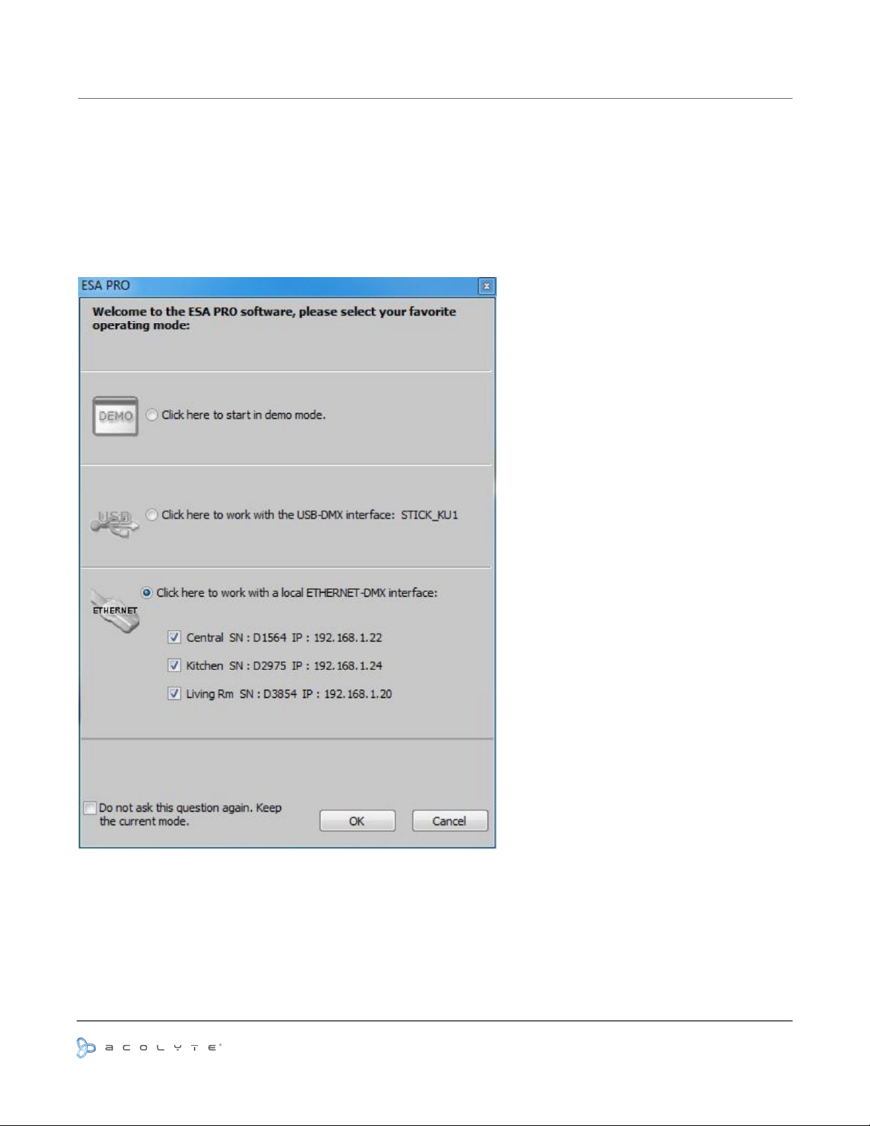
NETWORK CONTROL
It is possible to control a compatible DMX controller over a network in the same way as you would over USB.
Make sure your Ethernet enabled controller is set up correctly and connected to your network, then start ESA
Pro.
The start-up dialog will display all connected interfaces. Select the controllers you would like to use.
Use or reprinting prohibited unless explicitly approved by Acolyte Industries.
All artwork and images copyright Acolyte Industries Inc.
PAGE 24
Page 26
NETWORK CONTROL
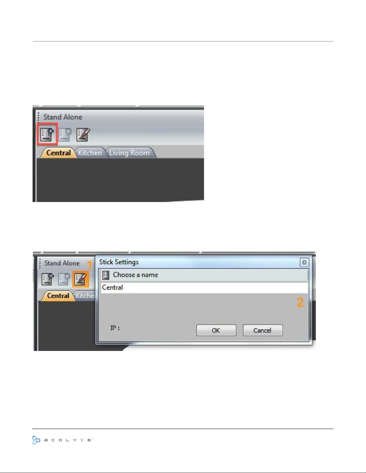
WRITING A SHOW TO A TOUCH CONTROLLER OVER THE NETWORK
While you are building your show, all controllers will output the same DMX signal in real time. Select the Stand
Alone tab to assign scenes to the controller. Click here to add a controller. In this example we have 3 touch
sensitive controllers.
Click here (1) to assign a hardware controller to each tab. Select from one of the connected controllers here
(2).
Use or reprinting prohibited unless explicitly approved by Acolyte Industries.
All artwork and images copyright Acolyte Industries Inc.
PAGE 25
Page 27
NETWORK CONTROL
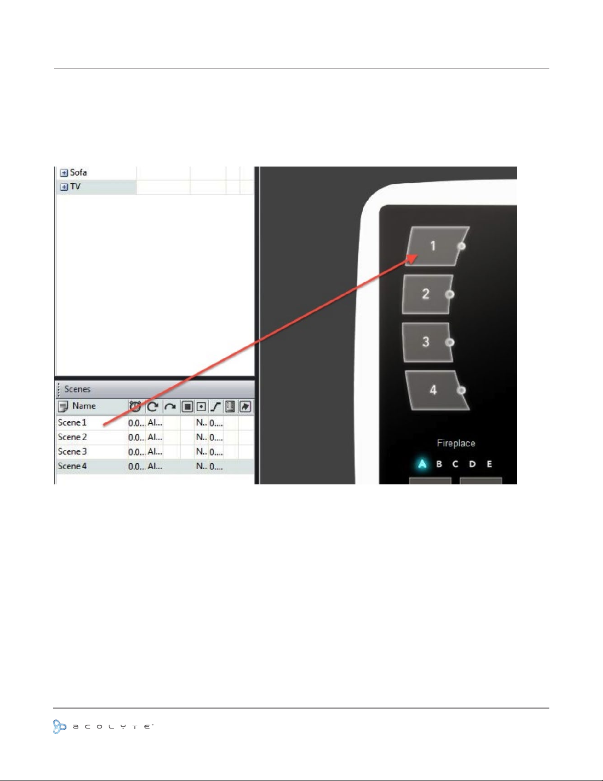
WRITING A SHOW TO A TOUCH CONTROLLER OVER THE NETWORK
Drag the scenes from the left to each controller on the right. Remember that there is a restriction to the total
number of areas you can use per controller depending on the device being used.
Use or reprinting prohibited unless explicitly approved by Acolyte Industries.
All artwork and images copyright Acolyte Industries Inc.
PAGE 26
Page 28
NETWORK CONTROL
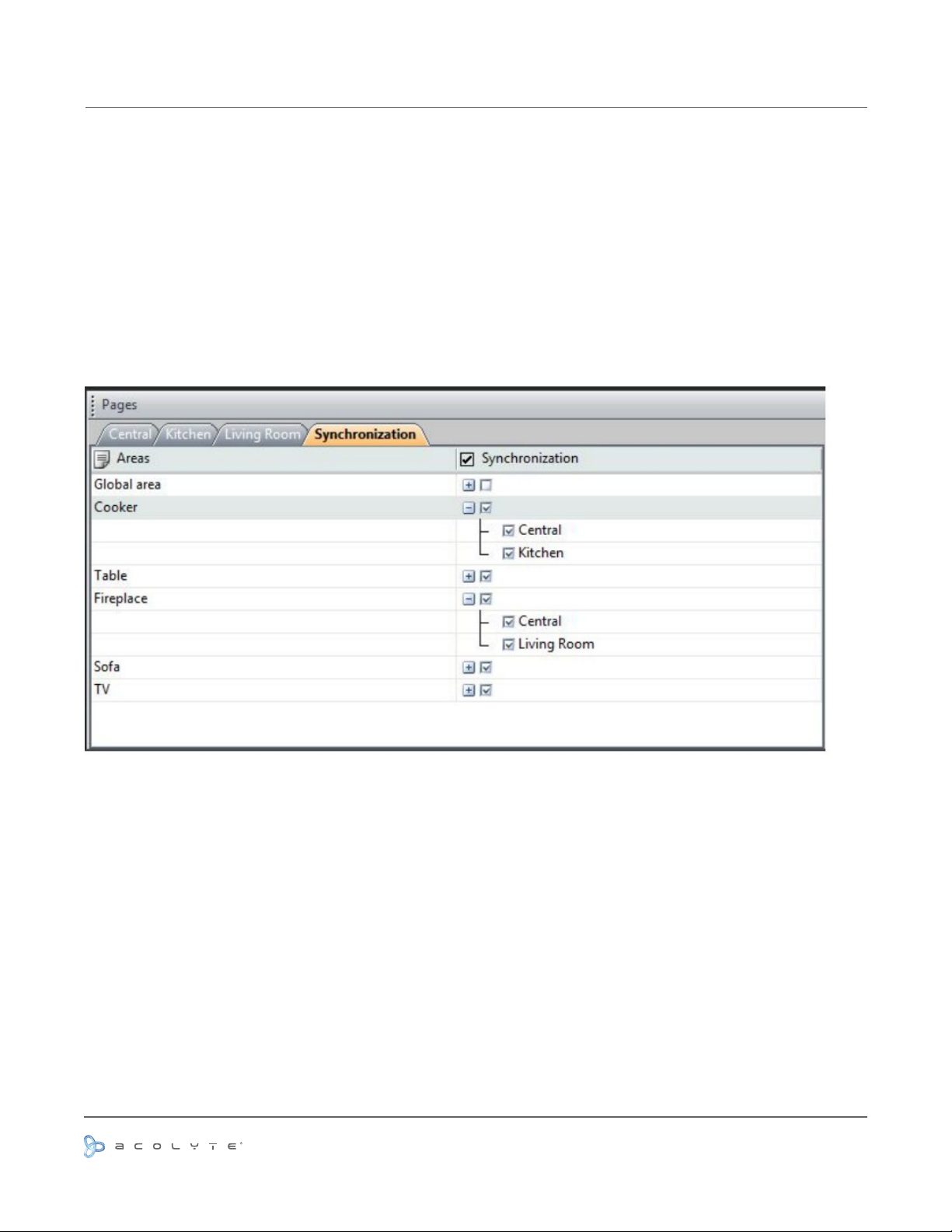
SYNCHRONIZATION OF TOUCH CONTROLLERS
It is possible to choose certain areas to synchronize between controllers. To do this:
- click the Synchronization tab
- click the area you would like to synchronize
- select which controllers you want to use for the synchronization
It is possible to synchronize areas even if they are on different pages. In this example, the ‘Cooker’ area is on
page B of the Central controller, and on page A of the Kitchen controller.
Use or reprinting prohibited unless explicitly approved by Acolyte Industries.
All artwork and images copyright Acolyte Industries Inc.
PAGE 27
Page 29
NETWORK CONTROL
SYNCHRONIZATION OF USB-ETHERNET CONTROLLERS
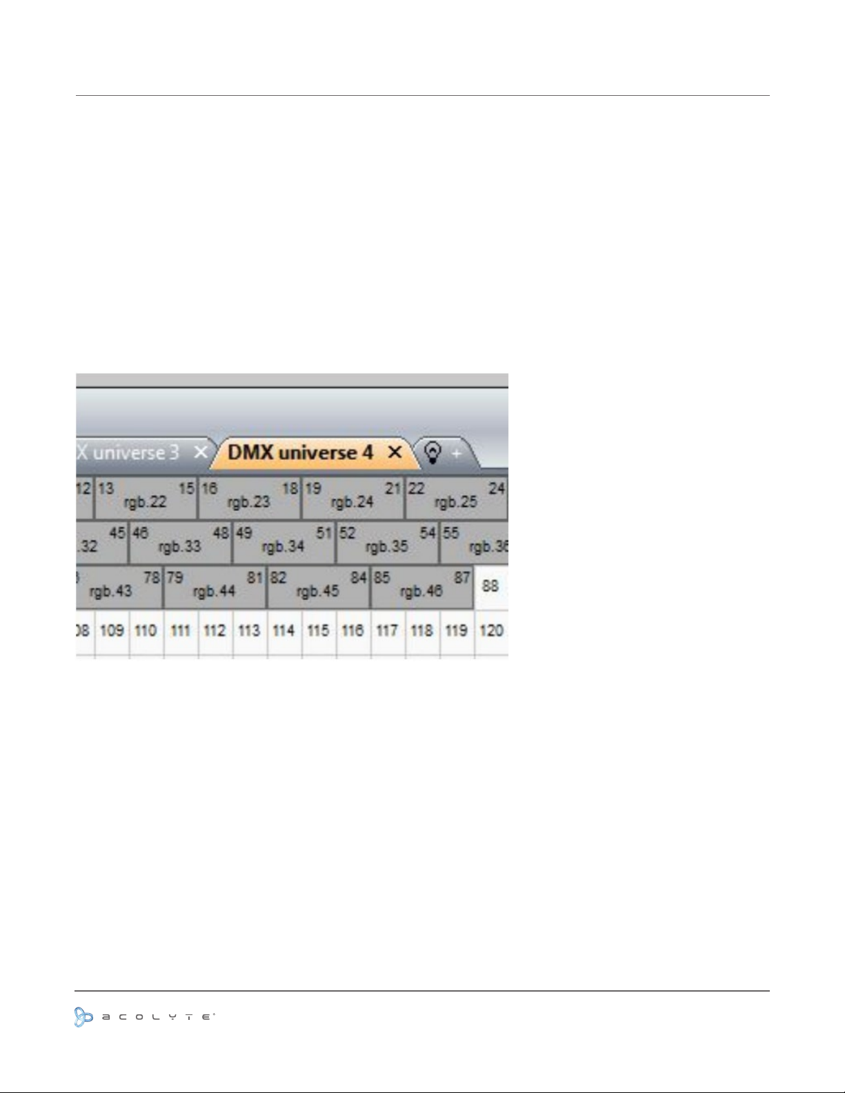
Several USB-Ethernet controllers can be synchronized to make a stand alone show with more than 2 universes.
Note that this is not compatible with the touch controllers.
To begin with, be sure that all USB-Ethernet controllers are connected to a switch or router. By default,
the controller is set to take the IP address from the router. If your router doesn’t have DHCP (automatic IP
addressing) enabled, connect your controller to your computer by USB and open the tools application to set a
manual IP address. See the ‘Hardware tools’ topic of the hardware manual for more information.
Once your interfaces are connected, start the ESA Pro software and select the controllers from the start-up
dialog.
Additional universes can be added in the patch window.
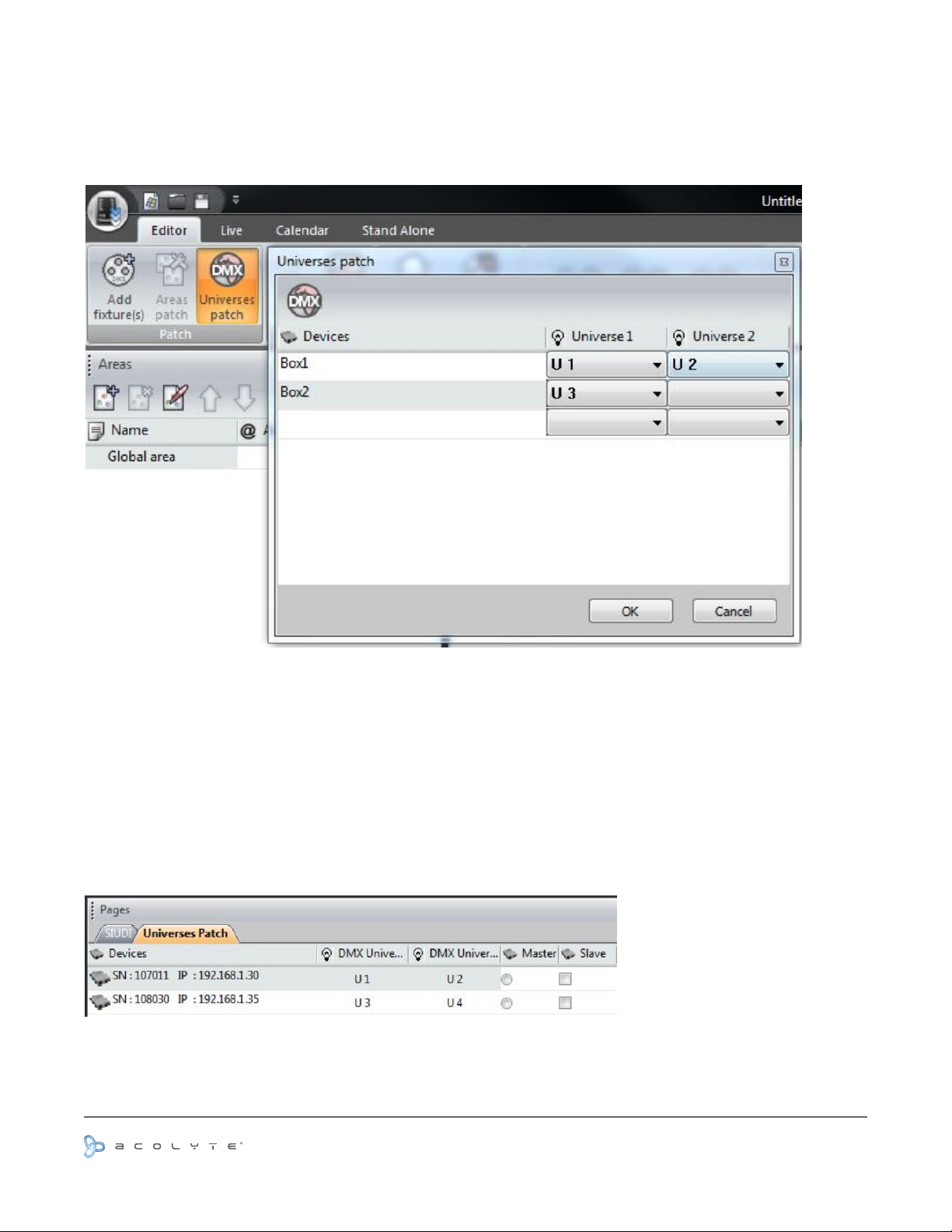
The DMX universes can be assigned to the appropriate controllers by clicking the ‘Universes Patch’ button.
The IP addresses of the detected controllers appear on the left. If you have no controllers connected and want
to write the show to the computer, create a name for each controller by double clicking on the appropriate
cell. The combo boxes are used to assign a software universe to one of the 2 DMX output universes on the
controller. Click the DMX icon in the top left to automatically assign the universes in IP address order.
PAGE 28
Use or reprinting prohibited unless explicitly approved by Acolyte Industries.
All artwork and images copyright Acolyte Industries Inc.
Page 30
NETWORK CONTROL
SYNCHRONIZATION OF USB-ETHERNET CONTROLLERS
To write your show to stand alone, assign the scenes in the same way as with a 2 universe show by dragging
and dropping onto the table, and then choose a master and slave within the pages window. When a scene
is changed on the master controller, the slave controllers will follow. This works whether the scene has
been triggered by the buttons on the interface, clock and calendar, jump, infra red or dry contact ports. The
synchronization timing is accurate to 1 DMX frame making this an ideal solution for the control of a large
matrix.
If you wish to write your show on the computer, a folder will be created for each interface. Insert each SD card
one by one into the computer and copy the appropriate ‘Show 1’ folder to the root of the corresponding SD
card.
PAGE 29
Use or reprinting prohibited unless explicitly approved by Acolyte Industries.
All artwork and images copyright Acolyte Industries Inc.
 Loading...