

Page 1

User Manual
PCH3591/3791/3991: 15/17/19” Industrial Fanless Panel PC
with P8400 2.26GHz processor
PCH3591/3791/3991
15/17/19 inch Fanless Panel PC
14628 Ce ntral Ave,
Chino , CA 91710
tel:909.597.7 588, fax:909.597.1939
© Copyright 2013 Acnodes, Inc.
All righ ts reserved. Product descripti on and product speci ficat ions
are subj ect to change w ith out n oti ce. F or lates t product inform ati on,
ple ase vis it Acnod es’ we b site at www.ac nodes.c om.
Page 2

PCH3591/3791/3991
Warning!
This equipment generates, uses and can radiate radio frequency energy and if not installed and
used in accordan ce with th e instructions manual, it may cause interference to radio communications.
It has been tested and found to comply with the li mits for a Class A comp uting devic e pursuant to
FCC Rules, whic h are designed to provid e reasonable protection against such interference when
operated in a com mercial environment. Operation of this equipm ent in a residential area is likely
to cause interference in which case the user at his own expense w ill be required to take whatever
measures ma y be required to co rrect th e interference.
Elect ric Shock Hazard – Do not operate the machi ne with its back cover removed. There are
dangerous high voltages inside.
15/17/19 inch Fanless Panel PC
14628 Ce ntral Ave,
Chino , CA 91710
tel:909.597.7 588, fax:909.597.1939
© Copyright 2013 Acnodes, Inc.
All right s reser ved . Produc t descr ipt ion and product speci fi cat io ns
are subj ect to change w ith out n oti ce. F or lates t product inform ati on,
ple ase vis it Acnod es’ we b site at www.ac nodes.c om.
Page 3

Packing List
Accessories (as ticked) included in this package are:
AC power cable
Driver & manual CD disc
Other._____________ (please specify)
Safety Precautions
Follow the messages below to p reven t your systems from damage:
Avoid your system from static electricity on all occasions.
Prevent electric shock. Don’ttouch any components of this card when the card
is power-on . Always disconnect power when the system is not in use.
Disconnect power when you change any hardware devices. For instance, when
you connec t a jumper o r install any cards, a surge of power may damage the
elec tronic components or the whole system.
PCH3591/3791/3991
15/17/19 inch Fanless Panel PC
14628 Ce ntral Ave,
Chino , CA 91710
tel:909.597.7 588, fax:909.597.1939
© Copyright 2013 Acnodes, Inc.
All righ ts reserved. Product descripti on and product speci ficat ions
are subj ect to change w ith out n oti ce. F or lates t product inform ati on,
ple ase vis it Acnod es’ we b site at www.ac nodes.c om.
Page 4

PCH3591/3791/3991
Table of Contents
Warning!………………………………………………………………………… ….……..….2
Packing List…………………………………………………………………………………..3
Safety Precautions……………………………………………………………………… …..3
Chapter 1 Getting Started
1.1 Specifications……………………………………..….……………………..6
1.2 Dimensions………………………………...………………………….......7
1.3 Brief Description…………………………………………………….……10
Chapter 2 Hardware
2.1 Mainboard………………..…….……………………………………..…..11
2.2 Installations…….………………….……………………………………...12
2.2.1 Jumpers Setting and Connectors………………………………….....12
2.3 Jumpers Setting and Connectors........................................................13
Chapter 3 BIOS Setup
3.1 Operations after POST Screen.............................................................24
3.2 BIOS SETUP UTILITY..........................................................................25
3.3 System Overview..................................................................................26
3.4 Advanced Settings............................................................................... 27
3.5 Advanced PCI/PnP Settings................................................................ 36
3.6 Boot Settings....................................................................................... 38
3.7 Security Settings.................................................................................. 40
3.8 Advanced Chipset Settings.................................................................. 41
3.9 Exit Options..........................................................................................48
15/17/19 inch Fanless Panel PC
14628 Ce ntral Ave,
Chino , CA 91710
tel:909.597.7 588, fax:909.597.1939
© Copyright 2013 Acnodes, Inc.
All right s reser ved . Produc t descr ipt ion and product speci fi cat io ns
are subj ect to change w ith out n oti ce. F or lates t product inform ati on,
ple ase vis it Acnod es’ we b site at www.ac nodes.c om.
Page 5

PCH3591/3791/3991
Chapter 4 Installation of Drivers
4.1 Chipset Driver.…………………………...……...…………………………51
4.2 Graphics Media Accelerator Driver...………………..…………………..54
4.3 Network Adapter……..……………………………………………….…….57
4.4 Realtek ALC662 HD Audio Driver Installation…….………….…………60
Chapter 5 Touch Screen Installation
5.1 Introduction to Controller Board..…………………………..……………62
5.2 Windows 2000/XP USB Driver Installation for 5000 Boards………..….62
Figures
Figure 1.1:Dimensions of PCH3591.…………………………………..…....7
Figure 1.2: Dimensions of PCH3791….………………………………..…....8
Figure 1.3:Dimensions of PCH3991….……………………………………….9
Figure 1.4: Front View of PCH3X91…….…………………………………...10
Figure 1.5: Rear View of PCH3X91…….…………………………………..10
Figure 2.1: Mainboard Dimensions…………………………………..…….....11
Figure 2.2: Jumpers and Connectors Location_ Board Top………………...12
Figure 2.3: Jumpers and Connectors Location_ Board Bottom…………....13
Figure 5.1 Birdeye? s View of Control Board………………………………62
15/17/19 inch Fanless Panel PC
14628 Ce ntral Ave,
Chino , CA 91710
tel:909.597.7 588, fax:909.597.1939
© Copyright 2013 Acnodes, Inc.
All righ ts reserved. Product descripti on and product speci ficat ions
are subj ect to change w ith out n oti ce. F or lates t product inform ati on,
ple ase vis it Acnod es’ we b site at www.ac nodes.c om.
Page 6

Chapter 1 System
1.1 Specifications
Specs
PCH3591
PCH3791
PCH3991
CPU
Socket P processor support up to P8400 2.26GHz without fan
Chipset
GM45 + ICH9M
System Memory
1 x 204 Pin 800MHz DDR3 SODIMM slot, up to 4GB
Display Size
15”17”19
”
Maximum Colors
262K
16.7M
16.2M
Viewing Angle (Degree)
H:160 / V:145
H:170 / V:160
H:170 / V:160
Luminance (cd/m²)
400
350
350
Backlight Lifetime
50,000 Hours
Rating
IP65
Tou ch Screen Type
Resistive Touch Screen (option)
Outside I/O port
2 x USB2.0 connectors
1 x GbE RJ45 LAN connector
1 x DB-9 RS-232 (COM1)
1 x DB-9 RS-422/485 (COM3), d efault RS-485
1 x DC Power Inp ut
Extension
None
Storage
1 x 2.5" SATA HDD
1 x Internal CF Slot
OS Support
Windows XP Professional, XP Embedded, Windows 7 Pro for Embedded, Windows
Embedded Standard 7
Power Supply
11~32V DC
Construction
Stainless steel
Dimensions (WxHxD)
410 x 310 x 8 7.8 mm
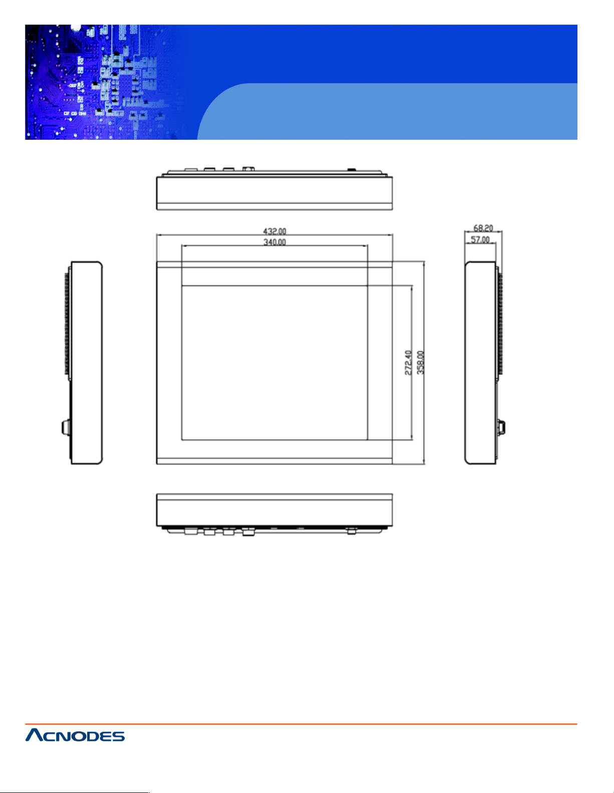
439 x 348 x 93.3 mm
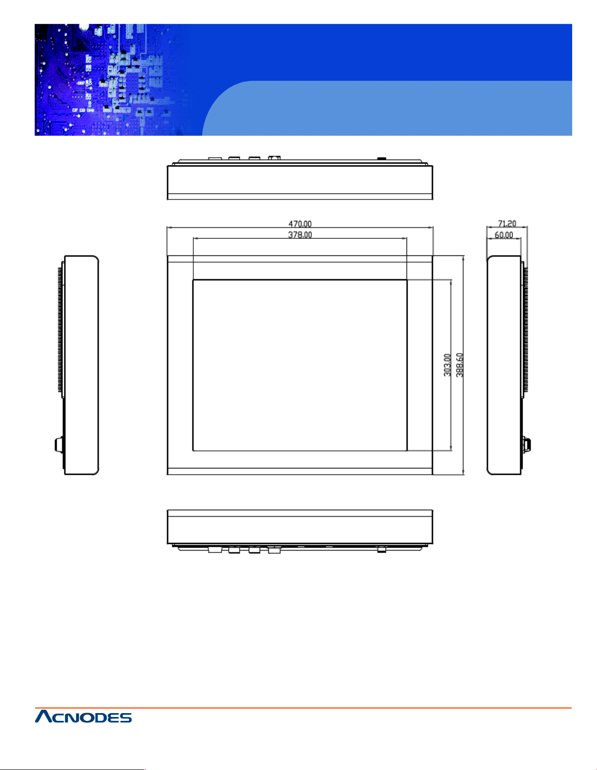
484 x 400 x 94.3 mm
Mounting
VESA 100x100/200x100
Mount
VESA 75x75 Mount
VESA 100x100 Mount
Operating Temperature
-10~50℃
Storage Temperature
-20~60
Relative Humidity
10%~90%@ 40 , non-condensing
Certificate
CE / FCC Class A
Page 7
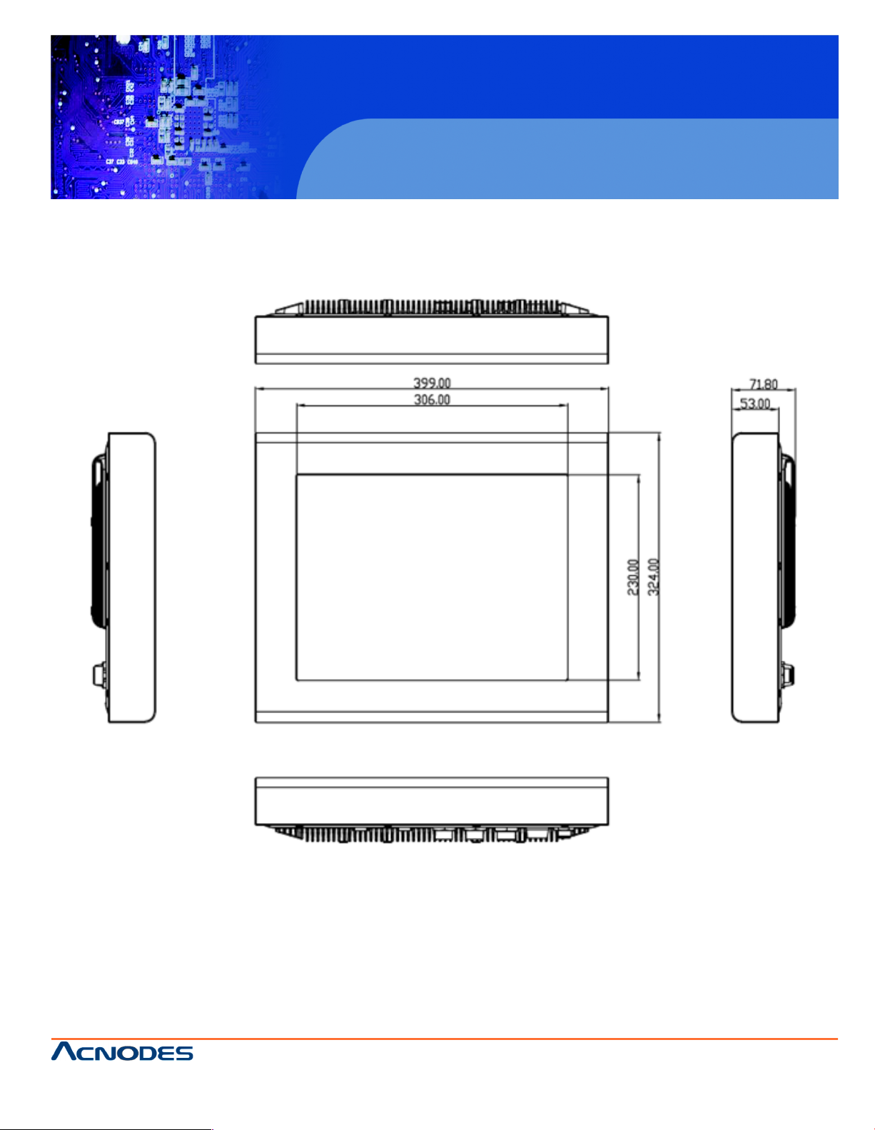
1.2 Dimensions
Figure 1.1: Dimensions of PCH3591
PCH3591/3791/3991
15/17/19 inch Fanless Panel PC
14628 Ce ntral Ave,
Chino , CA 91710
tel:909.597.7 588, fax:909.597.1939
© Copyright 2013 Acnodes, Inc.
All righ ts reserved. Product descripti on and product speci ficat ions
are subj ect to change w ith out n oti ce. F or lates t product inform ati on,
ple ase vis it Acnod es’ we b site at www.ac nodes.c om.
Page 8
PCH3591/3791/3991
Figure 1.2: Dimensions of PCH3791
15/17/19 inch Fanless Panel PC
14628 Ce ntral Ave,
Chino , CA 91710
tel:909.597.7 588, fax:909.597.1939
© Copyright 2013 Acnodes, Inc.
All right s reser ved . Produc t descr ipt ion and product speci fi cat io ns
are subj ect to change w ith out n oti ce. F or lates t product inform ati on,
ple ase vis it Acnod es’ we b site at www.ac nodes.c om.
Page 9
PCH3591/3791/3991
Figure 1.3: Dimensions of PCH3991
15/17/19 inch Fanless Panel PC
14628 Ce ntral Ave,
Chino , CA 91710
tel:909.597.7 588, fax:909.597.1939
© Copyright 2013 Acnodes, Inc.
All righ ts reserved. Product descripti on and product speci ficat ions
are subj ect to change w ith out n oti ce. F or lates t product inform ati on,
ple ase vis it Acnod es’ we b site at www.ac nodes.c om.
Page 10
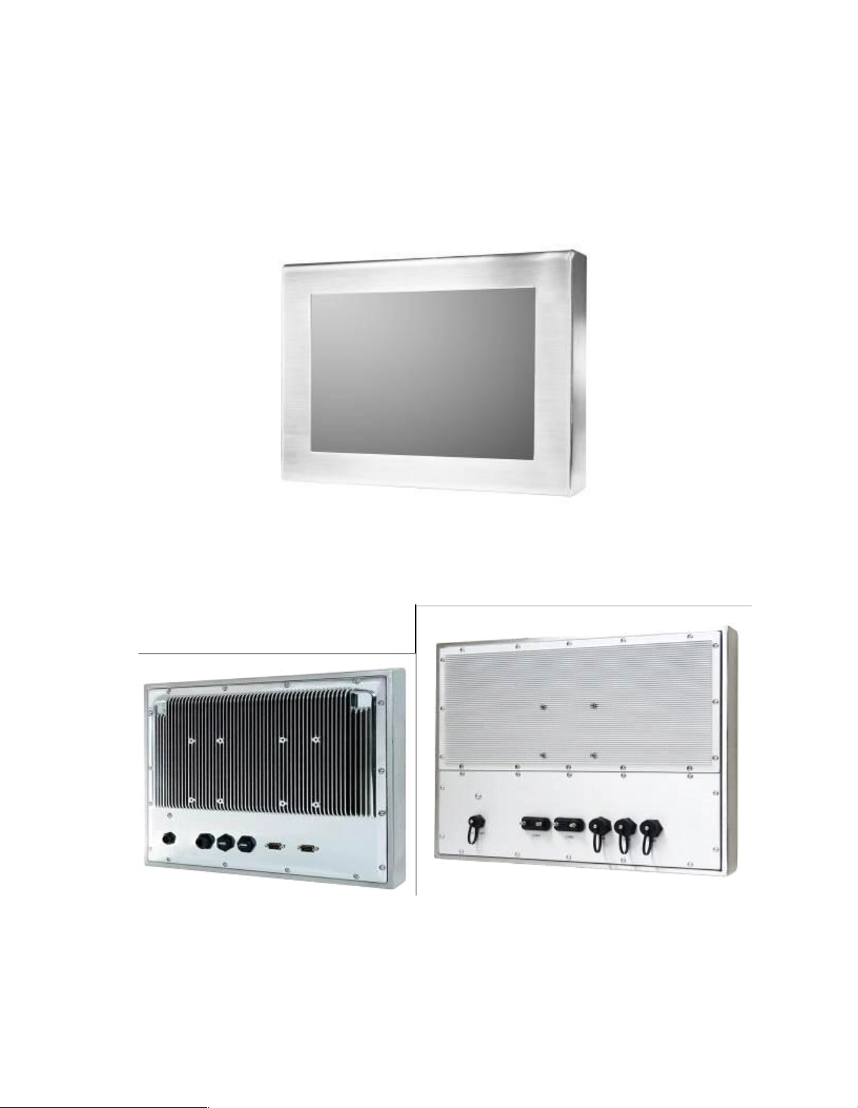
1.3 Brief Description of the PCH3X91
The PCH3591/3791/3991 is a stainless steel and VESA-mount industrial Panel PC, which comes with
a 15-inch (luminance of 400 cd/m²)/17-inch (luminance of 350 cd/m²)/19-inch (luminance of 350
cd/m²) TFT LCD. It is powered by a Socket P Core 2 Duo Processor, up to Intel P8400 2.26GHz
processor. The industrial panel PC also features two COM ports, two USB 2.0 ports, one 2.5”
HDD,
one internal CF slot, and 11~32V DC, etc. It is ideal for use as a PC-based controller for
Industrial Automation & Factory Automation
Figure 1.4: Front View of PCH3X91
PCH3591 PCH3791/3991
Figure 1.5: Rear View of PCH3X91
Page 11
PCH3591/3791/3991
Chapter 2 Hardware
2.1 Mainboard
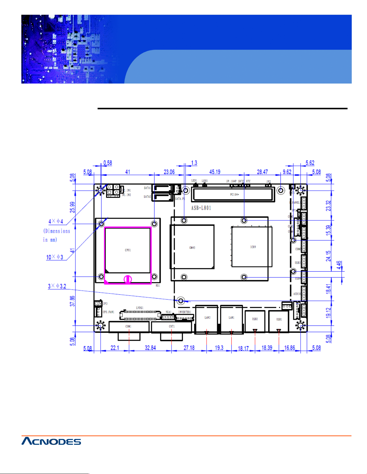
Figure 2.1: Mainboard Dimensions
15/17/19 inch Fanless Panel PC
14628 Ce ntral Ave,
Chino , CA 91710
tel:909.597.7 588, fax:909.597.1939
© Copyright 2013 Acnodes, Inc.
All righ ts reserved. Product descripti on and product speci ficat ions
are subj ect to change w ith out n oti ce. F or lates t product inform ati on,
ple ase vis it Acnod es’ we b site at www.ac nodes.c om.
Page 12
PCH3591/3791/3991
2.2 Installations
ASB-L801 is a 4" industrial Embedded motherboard developed on the basis of Intel G M45+
ICH9M, which provides abundant peripheral interfaces to meet the needs of d ifferent customers. Also,
it features dual 1000M LAN port, 5-COM port and d ual Mini PCIE configuration. To satisfy the special
nee ds of high-end customers, PC104+ port (capable of adjustin g IO voltage) richer extension
functions. Due to its compact size, the product is widely used in various sectors of industrial control..
2.2.1 Jumpers Setting and Connectors
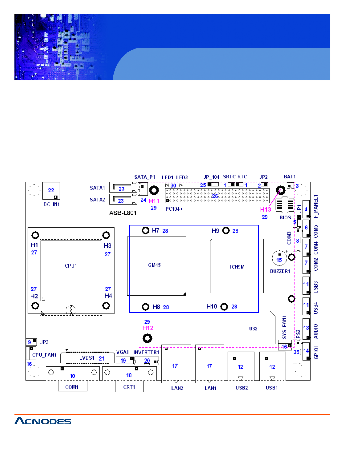
Figure 2.2: Jumpers and Connectors Location_ Board Top
15/17/19 inch Fanless Panel PC
14628 Ce ntral Ave,
Chino , CA 91710
tel:909.597.7 588, fax:909.597.1939
© Copyright 2013 Acnodes, Inc.
All right s reser ved . Produc t descr ipt ion and product speci fi cat io ns
are subj ect to change w ith out n oti ce. F or lates t product inform ati on,
ple ase vis it Acnod es’ we b site at www.ac nodes.c om.
Page 13
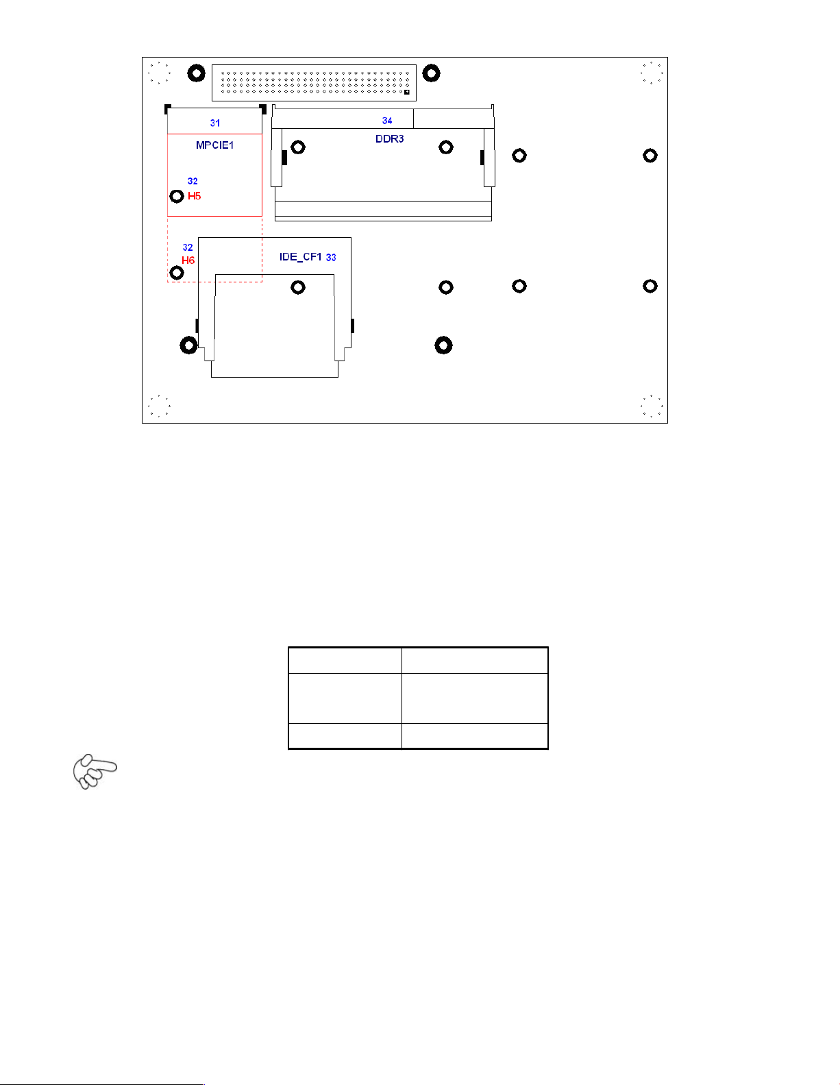
Figure 2.3: Jumpers and Connectors Location_ Board Bottom
2.3 Jumpers Setting and Connectors
1. RTC/SRTC: (2.0mm Pitch 1X2 Pin Header)CMOS cle ar jumper, CMOS clear
operation will perman ently reset old BIOS settings to fa ctory defaults.
RTC/SRTC
CMOS
OPEN
NORMAL
(default)
CLOSE 1 -2
Clear CMOS
Procedures of CMOS clea r:
5.4.1.1 Turn off the system and unplug the power cord from the power outlet.
5.4.1.2 To cle ar the C MOS s ettings, use the jumper cap to close pins1 and 2 fo r about
3 seconds then reinstall the jumper clip back to pins open.
5.4.1.3 Power on the system again.
5.4.1.4 When entering the POST screen, press the <F1> or <DEL> key to enter CMOS
Setup Utility to load optimal defaults.
5.4.1.5 After the above operations, save changes a nd exit BIOS Setup.
2. JP2: (2.0mm Pitch 1X2 Pin Header), ATX Power and AT Power s etting jumper.
Page 14

JP2
Mode
Open
ATX Power
Mode
Close
Auto Power on
3. BAT1: (1.25mm Pitch 1X2 box Pin Header) 3.0V Li battery is embedded to
provide power for CMOS.
Pin#
Signal
Nam e
Pin1
VBAT
PIN2
Ground
4. F_PANEL: (2.0mm Pitch 2X5 Pin Head er), Front panel connector.
Signal Name
Pin#
Pin#
Signal Name
HD LED+
12POWER
LED+
Ground
34Ground
Ground
56SW +
RESET+
78Ground
SPK+
910SPK-
Pin1-3: HDD LED, They are used to co nnect hard disk a ctivity LED. The LED blinks
when the hard disk is reading or writing data.
Pin2-4: POWER LED, They are used to connect power LED. W hen th e system is
powered on or under S0/S1 state, the LED is normally on; when the
system is under S4/S5 state, the LED is off.
Pin5-6: POWER on/off Button, They are used to connect powe r switch button.
The two pins are disconnected under normal condition. You may short
them temporarily to realize system startup & sh utdown or awaken the
system from sleep state.
Pin7-8: RE SET Button, They are used to connect reset button. The two pins are
dis-
connected under normal condition. You may short them temporarily to
realize
system reset.
Pin9-10: BUZZER , They are used to connect an external buzzer.
Page 15

Note:
W hen connecting LEDs and buzzer, pa y special attention to the si gnal
pola-
rity. Mak e sure that the connector pins have a one-to-one correspondence
with chassis wiring, o r it may cause boot up failure.
5. JP1: (2.0mm Pitch 1x3 Pin Header) COM5 s etting jumper, pin 1 ~3 are used to
select signal out of pin 10 of COM5 port.
JP1 Pin#
Function
Close 1-2
COM5 Pin10=+5V (default)
Close 2-3
COM5 Pin10=+12V (option)
6. COM5: (2.0mm Pitch 2X5 Pin Header), COM5 Port, standard RS232 ports are
provide d. They can be used directly via COM cable conne ction.
Signal
Nam e
Pin#
Pin#
Signal Name
DCD12
RXD
TXD34
DTR
Ground
56DSR
RTS78
CTS
RI910
Jp1 Setting:
Pin1-2 : 5V
(default)
Pin2-3:12V
(option)
7. COM2/COM4: (2.0mm Pitch 2X5 Pin Header),CO M2 COM4 Port, up to 2
standard RS232 ports are provided. They can be used directly via COM cable
connection.
Signal
Nam e
Pin#
Pin#
Signal Name
DCD12
RXD
TXD34
DTR
Page 16
Ground
56DSR
RTS78
CTS
RI910
NC
8. COM3: (2.0mm Pitch 1x6 box Pin Header),it provides selectable RS422/RS485
serial signal output from BIOS configuration.
RS422 Type (option)
RS485 Type (default)
Signal Name
Pin#
Pin#
Signal Name
422RX-
11NC
422RX+
22NC
422TX-
33485-
422TX+
44485+
Ground
55Ground
+5V66
+5V
NC77
NC
NC88
NC
NC99
NC
9. JP3: (2.0mm Pitch 2x3 Pin Header),COM1 s etting jumper, pin 1~6 are used to
selec t signal out of pin 9 of COM1 port.
JP3 Pin#
Function
Close 1 -2
RI (Ring Indicator)
(default)
Close 3-4
COM1 Pin9=+5V (option)
Close 5-6
COM1 Pin9=+12V (option)
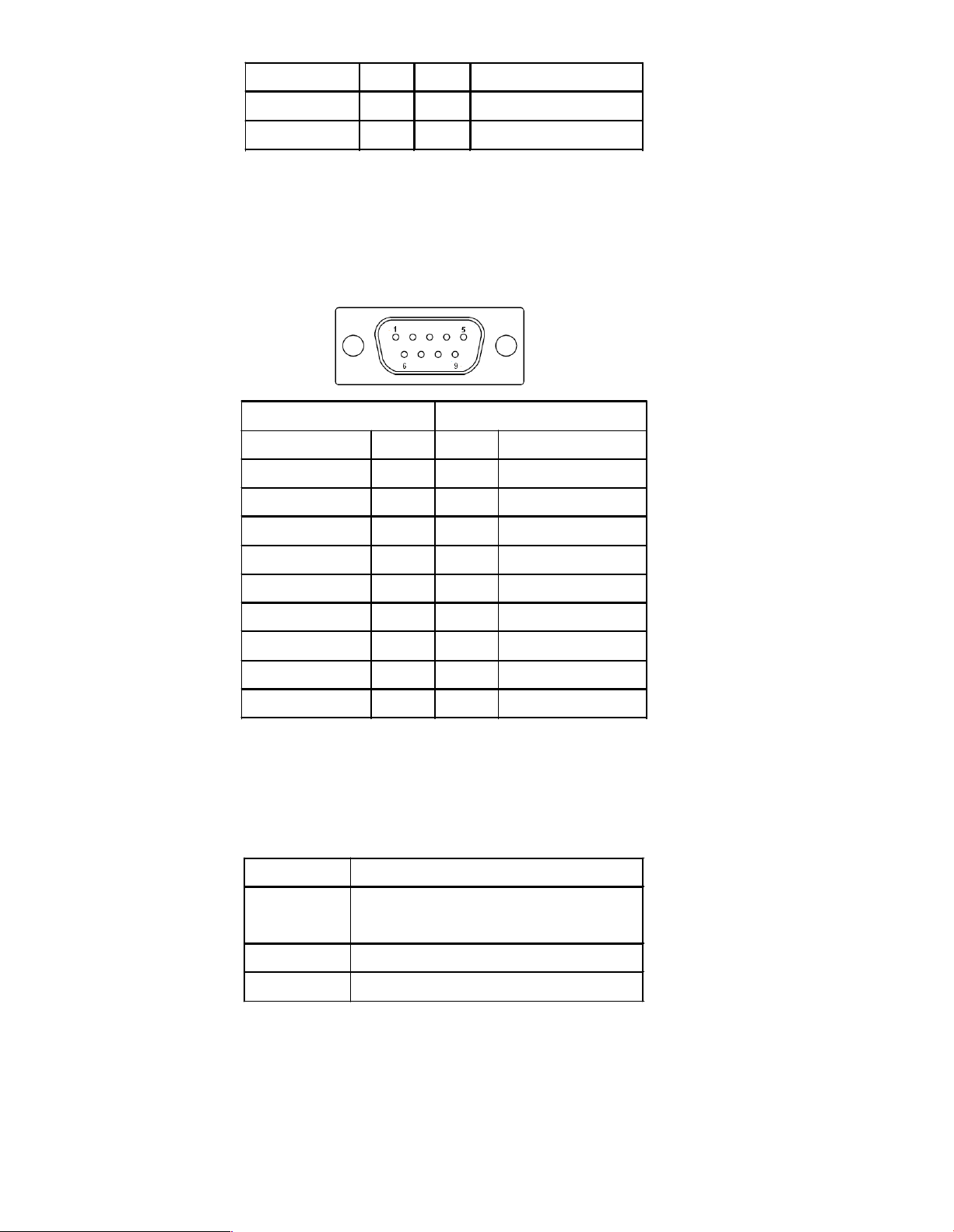
10. COM1: (Type DB9),Rear serial port, standard DB9 serial po rt is
provide d to make a direct con nection to serial devices. COM1 port is controlled by
pins No.1 ~6 of JP3,select output Signal RI or 5V or 12v, For details, please refer to
description of J P3.
Page 17
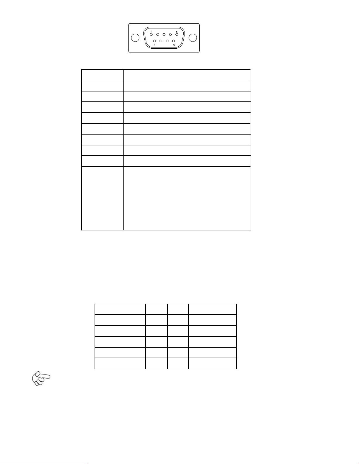
Pin#
Signa l Name
1
DCD# (Data Carrier Dete ct)
2
RXD (Received D ata)
3
TXD (Transmit Data)
4
DTR (Data Terminal Ready )
5
Ground
6
DSR (Data Set Ready)
7
RTS (Request To Send)
8
CTS (Clea r To Send)
9
JP1 Setting:
Pin1-2 : R I (Ring Indica tor)
(default)
Pin3-4 : 5V Standby power (option)
Pin5-6:12V Standby power
(option)
11. USB3/USB4: (2.0mm Pitch 2X5 Pin H eader) ,Front USB connector, it
provides 4 USB ports via a dedicated USB cable, speed up to 480Mb/s.
Signal Nam e
Pin#
Pin#
Signal Name
VCC(+5V)
12VCC(+5V)
USB_DB-
34USB_DA-
USB_DB+
56USB_DA+
Ground
78Ground
NC910
Ground
Note:
Before connection, make sure that pinout of the USB C able is in accordance with th at
of the said tables. Any inconformity may c ause system down and even hardware
damages.
Page 18
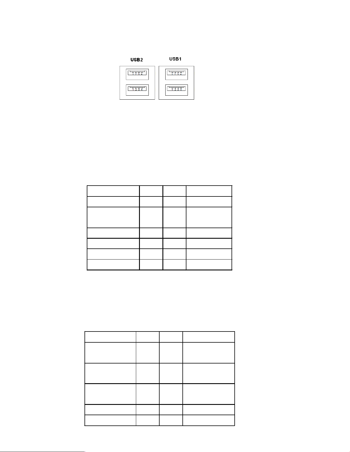
12. USB1/2: (Double stack USB type A), Rear USB connector, it provides up to 4
USB2.0 ports, speed up to 480Mb/s.
13. AUDIO: (2.0mm Pitch 2X6 Pin Header), Front Audio, An onboard Realtek
ALC662 codec is used to provide high-quality audio I/O ports. Line Out can be
connected to a headphone or amplifier. Line In is used for the connection of
external audio source via a Line in cable. MIC is the port for microphone input
audio.
Signal Name
Pin#
Pin#
Signal Name
VCC(+5V)
12Ground
LINE_OUT_L
34LINE_OUT_
R
FRO NT_JD
56LINE1_JD
LINE_IN_L
78LINE_IN_R
MIC _IN_L
910MIC _IN_R
Ground
11
12
MIC 1_JD
14. GPIO1: (2.0mm Pitch 2x5 Pin Header),General-purpose input/ou tput p ort, it
provides a group of self -programming in terfaces to customers for flexible u se.
Signa l Name
Pin#
Pin#
Signal Name
Ground
12GPIO18_OUT
1
GPIO20_OUT
2
34GPIO33_OUT
3
GPIO34_OUT
4
56GPIO18_IN1
GPIO20_IN2
78GPIO33_IN3
GPIO34_IN4
910+5V
Page 19
15. BZ: onboard buzzer.
16. CPU_FAN/SYS_FAN1: (2.54mm Pitch 1x3 Pin He ader),Fan connector,
cooling fans can be connected directly f or use . You may set the rotation condition of
cooling fan in menu of BIOS CMOS Setup.
Pin#
Signal Nam e
1
Ground
2
VCC
3
Rotation
detection
Note:
Output powe r of cooling fan must be limited under 5W.
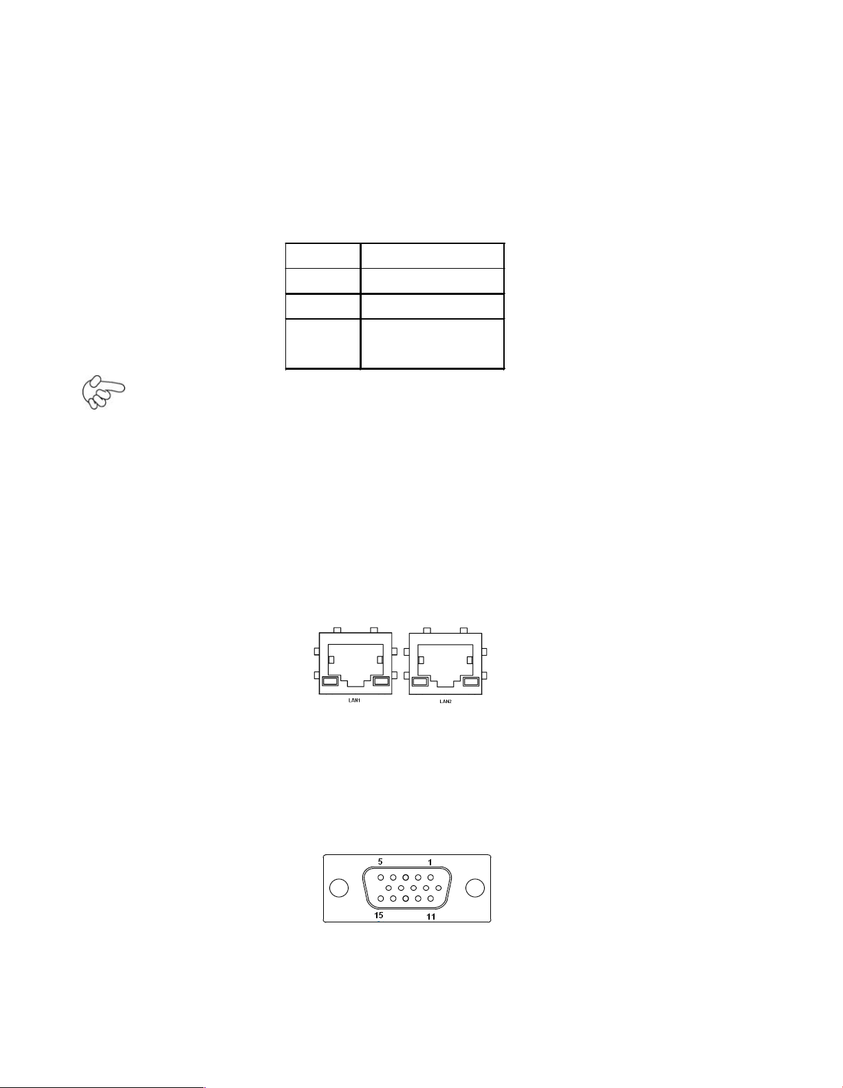
17. LAN1/2: (RJ45 Connector), Rear LAN port,2 standard 10/100/1000M RJ -45
Ethernet ports are provid ed. Used In tel 82574L chipset ,LINK LED (green ) and
ACTIVE LED (yellow) respective ly located a t the l eft-hand and right-hand side of the
Ethernet port indicate the activity and transmission state of LAN.
18. CRT1: (CRT Connector DB15),Video Graphic Array Port, provide high-quality
video output. They cannot w ork at the same time for CRT and VGA1.
19. VGA1: (CRT 2.0mm Pitch 2X5 Pin Head er), Video Graphic Array Port, Provide
2x5Pin cable to VGA Port, the y cannot work at the sa me time for CRT and VGA1.
Page 20
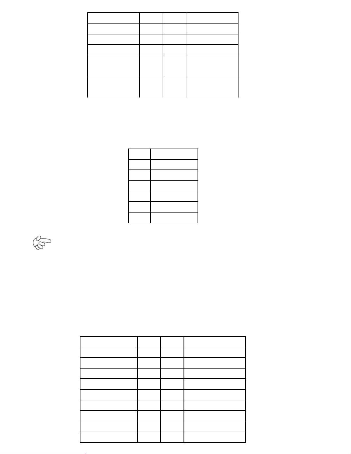
Signal Name
Pin#
Pin#
Signal Nam e
CRT_RED
12Groun d
CRT_GREEN
34Groun d
CRT_BLUE
56VGA_EN
CRT_H_SYN
C
78CRT_DDCDAT
A
CRT_V_SYNC
910CRT_DDCCL
K
20. INVERTER1: (2.0mm Pitch 1x6 box Pin H eader), Bac klight control
connect or for LVDS1.
Pin#
Signa l Name
1
+DC12V
2
+DC12V
3
Ground
4
Ground
5
BKLT_EN
6
BKLT_CTRL
Note:
Pin6 is backlight control signal, support DC or PWM mode, mode select at BIOS CMOS
menu.
21. LVDS1: For 18/24 bit LVDS output connector, Fully supported by Intel GM45
chipset, the interface features dual c hannel 18/24-bit output. Model name of the
interface connector is Hirose DF13-40DP-1.25V.
Signal Name
Pin#
Pin#
Signal Name
VDD521
VDD5
Ground
43Ground
VDD33
65VDD33
LB_D0_N
87LA_D0_N
LB_D0_P
10
9
LA_D0_P
Ground
12
11
Ground
LB_D1_N
14
13
LA_D1_N
LA_D1_P
16
15
LA_D1_P
Ground
18
17
Ground
Page 21
LB_D2_N
20
19
LA_D2_N
LB_D2_P
22
21
LA_D2_P
Ground
24
23
Ground
LB_CLK_N
26
25
LA_CLK_N
LB_CLK_P
28
27
LA_CLK_P
Ground
30
29
Ground
DS_DDC_DATA
32
31
LVDS_DOC_CLK
Ground
34
33
Ground
LB_D3_N
36
35
LA_D3_N
LB_D3_P
38
37
LA_D3_P
NC4039
NC
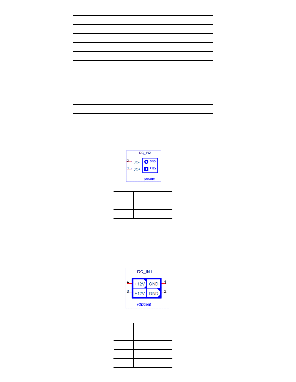
22. DC_IN2: (5.0mm 1x2 Pin Connector),DC 12V System power input connector
Pin#
Signal Name
1
+12V
2
Ground
DC_IN1: (2x2 box Pin Connector),DC12V System power input co nnector
Pin#
Signal Name
1
Ground
2
Ground
3
+12V
4
+12V
Page 22
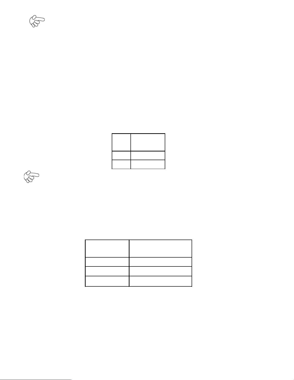
Note:
Make sure that the voltage of power supply is DC(12± 5%)V before power on, or
it may cause boot up failure and even system damage.
23. SATA1/2: (SATA 7P),SATA1,SATA2 SATA Connectors, Two SATA conne ctors are
provided, with transfer speed up to 3.0Gb/s.
24. SATA_P1: (2.5mm Pitch 1x2 box Pin Header),an onboard 5V output
connector is reserved to provide power for IDE/SATA devices.
Pin#
Signal
Name
1
+DC5V
2
Ground
Note:
Output current of the conne ctor must not be above 1A.
25. JP_104P: (2.0mm Pitch 1X3 Pin Head er) PC104+ port voltage selection jumper,
select voltage for PCI-104 Plus device. The default for this jumper is
“
all open
”
, meaning the user must select the voltage to be used.
JVCCIO
PC104+ VCCIO
Voltage
all O pen
Default
CLOSE 1-2
+3.3V PCI C ard
CLOSE 2-3
+5V PCI Card
26. PC104+: (4x30 Pin), PC104 plus connector, it conforms to standard PC104+
specification. Can expand support fou r PCI devices.
27. H1/H2/H3/H4: CPU FAN SCREW HOLES, Four screw holes for fixed CPU Cooler
assemble.
Page 23

28. H7/H8/H9/H10: GM45+ICH9M Heat Sink SCREW HOLES, Four screw holes for
intel GM45 and ICH9M Heat Sink assemble.
29. H11/H12/H13: PC104+ CARD SCREW HOLES, Three screw holes f or PC104+
card assemble.
30. LED1/LED3: LED STATUS. LED1:Motherboard Standby Power Good
status LED3: Mot herboard CPU Power Go od status.
31. MPCIE1: (30mmx30mm Socket 52Pin),mini PCIE socket, it is located at the
bottom, it supp orts mini PCI-E devices with USB2.0, SMBUS and PCI-E signal.
32. H5/H6: MPCIE1 SCREW HOLES, H5 for mini PCIE c ard (30mmx30mm Socket 52
Pin)
assemble. H6 Reserve.
33. IDE_CF1: (CF Card socket), it is located at the bo ttom of the board an d
serves as an insert interface for Type I and Type II Compact Flash card. The
operating voltage of CF card can be set as 3.3V or 5 V. The default setting of the
product is 3.3V.
34. DDR3: (SO-DIMM 204Pin socket), DDRIII memory socket, the so cket is located at
the bottom of the board and supports 204Pin 1.5V DDR III 800/1066MHz FSB
SO-DIMM memory module up to 4GB.
35. PS2: (2.0mm Pitch 1X6 box Pin He ader), PS/2 keyboard and mouse port, the
port can be connected to PS/2 keyboard or m ouse via a dedicated cable for direct
used.
Pin#
Signal
Name
1
KBDATA
Page 24

2
MSDATA
3
Ground
4
+5V
5
KBCL K
6
MSCLK
3 BIOS Setup Description
3.1 Operations after POST Screen
After CMOS discharge or BIOS flashing operation, the system will display the
following s creen for your further operation. Press F2 key to continue or F1 key to
enter CMOS Setup.
AMIBIOS©2006 American Mega trends , Inc.
BIOS Date: 03/08/11 2 3:27:33 Ver: 08.00.15
CPU : GenuineIntel(R) CPU 575 @ 2.00GHz
Speed : 2.00 GHz
Press F11 for BBS POPUP
Initializing US B Controllers. . Done.
2013M B OK
Auto-Detecting Pri Master.. IDE Hard Disk
Pri Master : Hitachi HTS545016B9A300 PB0C64G
Ultra DMA – 5, S.M.A.R.T. Capable and Status
OK Auto – detecting USB Mass Storage Devices ..
00 USB Mass storage devices found and configured
CMOS Settings Wrong
CMOS Data / Time Not Set
Press F1 to Run SETUP
Press F2 to load default values and continue
0085
After optimizing a nd exiting CMOS Setup, the POST screen displayed for the first time is
as follows and includes basic information on BIOS, CPU, memory, and storage devices.
AMIBIOS©2009 American Mega trends , Inc.
BIOS Date: 03/08/11 23:27:3 3 Ver: 08.00.15
CPU : GenuineIntel(R) CPU
575
@ 2.00GHz
Speed : 2.00 GHz
Press DEL to Run Setup
Press F11 for BBS POPUP
Page 25

Initializing USB Controllers. . Done.
2013MB OK
Auto-Detecting Pri Master.. IDE Hard Disk
Pri Master : Hitachi HTS545016B9A300 PB0C64G
Ultra DMA – 5, S.M.A.R.T. Capable and Status OK
Auto – detecting USB Mass Storage Devices ..
00 USB Mass storage devices found and configured.
Checking NVRAM..
0085
Press F11 key to enter Boot Menu during POST, as shown by th e following figure.
Please selec t boot device
Hitachi HTS545016B9A300
USB: USB Hotplug FDD
SATA:4M-C SS H AK40 -004G
?
and to move selection
ENTER to select Boot device
ESC to boot using defaults
3.2 BIOS SETUP UTILITY
Press [Del] ke y to enter BIOS Setup utility during POST, and then a main menu
containing system summary information will app ear.
BIOS SETUP UTILITY
Main
Advanced
PCIPnP
Boot
Security
Chipset
Exit
System Ove rview
User [ENTER] [TAB]
or [SHIFT-TAB] to
Select a field
Use[+] or [-] to
configure system Time.
AMIBIOS
Build Date : 03/08/11
ID : L801V 010
Processor
Genuine Intel(R) CPU 575 @ 2.00GHz
Speed :2000MHz
Page 26

Select Screen
Select Item
+- Charge Field
Tab Select Field
F1 General Help
F10 Save and Exit
ESC Exit
System Memory
Size :1981MB
System Time [00:0 1:09]
System Date [Tue
v02.61©Copyright 1985-2006 American Megatrends , Inc.
3.3 System Overview
BIOS SETUP UTILITY
Main
Advanced
PCIPnP
Boot
Security
Chipset
Exit
System Overview
User [ENTER] [TAB]
or [SHIFT-TAB] to
Select a field
Use[+] or [-] to
configure system Time.
Select Screen
Select Item
+- Charge Field
Tab Select Field
F1 General Help
F10 Save and Exit
ESC Exit
AMIBIOS
Version : 08.00.15
Build Date : 03/0 8/11
ID : L801V010
Processor
Genuine Intel(R) CPU 575 @ 2.00G Hz
Speed :2000MHz
System M emory
Size :1981MB
System Time [00:02:26]
System Date [Tue 03/08 /2011]
V02.61©Copyright 1985-2006 American Mega trends , Inc.
System Time:
Set the system time, the time format is:
Hour : 0 to 23
Minute : 0 to 59
Second : 0 to 59
System Date:
Set the system date, the date format is:
Day: Note that th e „ Day?automatically changes when y ou set the
Page 27

Month: 01 to 12
Date: 01 to 31
Year: 2009 to 2099
3.4 Advanced Settings
BIOS SETUP UTILITY
Main
Advanced
PCIPnP
Boot
Security
Chipset
Exit
Advanced Settin gs
Configure CPU
Select Screen
Select Item
Enter Charge Field
F1 General Help
F10 Save and Exit
ESC Exit
WARNING: Setting wrong values In below
sections
may cause system to malfunction.
? CPU Configuration
? IDE Configuration
? Super IO Configurati on
? Hardware Health Con figuration
? ACP I Configuration
? AHCI Configuration
? MPS Configuration
? PCI Express Configuration
? Smbios Configuratio n
? USB Configuration
V02.61©Copyr ight 1985-2006 American Mega trends , Inc.
3.4.1 CPU Configuration
BIOS SETUP UTILITY
Advanced
Configure adv anced CPU settings
Module Version: 3F.10
For UP platforms,
Leave it enabled.
For DP/MP serves,
Manufacturer : Intel
Page 28

Genuine Intel (R) CPU 575 @ 2.00 GHz
It may use to tune
Performance to the
Specific application.
Select Screen
Select Item
+- Charge Field F1
General Help F10
Save and Exit ES C
Exit
Frequency :2.00GHz
FSB Speed : 668MHz
Cache L1 :32 KB
Cache L2 :1024 KB
Ratio Actual Value :L2
Hardw are Prefetch er [Enabled]
Adjacent Cache Line Pre fetch [Enable d]
Max CPU ID Value Limit [Disabled]
Ex ecu te-Disable Bit Cap ability [Enabled]
Inte l(R) C-STATE tech [Disabled]
V02.61©Copyr ight 1985-2006 American Mega trends , Inc.
Hardware Prefetcher:
[Enabled]
[Disabled]
Adjacent Cache Line Prefetch:
[Enabled]
[Disabled]
Max CPUID Value Limit:
[Enabled]
[Disabled]
Execute-D isable Bit Capability:
[Disabled]
[Enabled]
Intel(R) C-STATE tech:
[Disabled]
[Enabled]
3.4.2 IDE Configuration
BIOS SETUP UTILITY
Advanced
Page 29

IDE Configur ation
Disabled
Compa tible
Enhanced
Select Screen
Select Item
+- Charge Field F1
General Help F10
Save and Exit ESC
Exit
SATA#1 Configuration [Compatible]
Configure SATA as [IDE]
SATA#1 Configuration [Enhanced]
? Primary IDE Master : [No t
Detected]
? Primary IDE Slaver : [Not
Detected]
? Secondar y IDE Master : [N ot
Detected]
? Secondar y IDE Slaver : [N ot
Detected]
? Third IDE Master : [Not
Detected]
? Fo urth IDE Master : [H ard
Disk]
Hard Disk Write Protect [Disabled]
IDE De tect Time Out (Se c) [35]
ATA(PI) 80Pin Cable Detection [Host &
Device]
V02.61©Copyright 1985-2006 American Mega trends , Inc.
SATA# 1 Configuration:
[Compatible]
[Disabled]
[Enhanced]
Configure SATA as:
[IDE]
[AHCI]
SATA# 2 Configuration:
[Enhanced]
[Disabled]
Hard Disk Write Protect:
[Disabled]
Page 30

[Enabled]
IDE Detect Time O ut :
[35]
[0]
[5,10,15,20,25,30]
ATA(PI) 80Pin Cable Detection:
[Host & Device]
[Host]
[Device]
3.4.3 Super IO Configuration
BIOS SETUP UTILITY
Advanced
Configure Win627UHG Super IO Chipset
Allow BIOS to Select
Serial Port Base
Address.
Select Screen
Select Item
+- Charge Field F1
General Help F10
Save and Exit ESC
Exit
Serial Port1 Address [3F8]
Serial Port2 Address [2F8]
Serial Port3 Address [3E8]
Serial Port3 IRQ [IRQ 4]
Serial Port3 Mode [RS-485]
Serial Port4 Address [2E8]
Serial Port4 IRQ [IRQ 3]
Serial Port5 Address [238]
Serial Port5 IRQ [IRQ 5]
V02.61©Copyright 1985-2006 American Mega trends , Inc.
Serial Port3 Mode:
COM3 Opti ons: [RS485 ]
[RS42 2]
[RS422] for RS422 Mode
[RS48 5] for RS485 Mod e
Page 31

3.4.4 Hardware Health Configuration
BIOS SETUP UTILITY
Advanced
Hardw are Hea lth Configuration
55 /131
?
60 /140
?
65 /149
?
70 /158
?
Select Screen
Select Item
+- Charge Field F1
General Help F10
Save and Exit ESC
Exit
System Temperature :36? /96
?
CPU Temperature :45? /113
?
CPUFAN Spee d :5018 RPM
Vcore :1.064V
AVC C :5.091 V
5VCC :5.100 V
3.3V :3.328 V
5.0V :5.01 V
12V :12.01 V
VSB :5.10 V
VBAT :3.400 V
Smart Fan Configuration
Maximum CPU Temperature [60? /140?]
Maximum PWM Duty for CPU Fan [60 %]
V02.61©Copyr ight 1985-2006 American Mega trends , Inc.
System Temperature:
Show you the current system temperature.
CPU Temperature:
Show you the current CPU temperature.
CPUFAN Speed:
Show you the current CPU Fan operating speed.
Maximum CPU Temperature:
[60 /140?]
[55 /131?]
[65 /149?]
[70 /158?]
Page 32

Minimum PWM Duty for CPU Fan:
[60% ]
[50%]
[70%]
[80%]
3.4.5 ACPI Configuration
ACPI Se tting:
[Advanced ACPI Configuration]
ACPI Version Features:
[ACPI V1.0]
[ACPI V2.0]
[ACPI V3.0]
ACPI APIC support:
[Enabled]
[Disabled]
AMI OEMB table:
Headless mode:
[Enabled]
[Disabled]
[Disabled]
[Enabled]
[Chipset ACPI Configuration]:
APIC ACPI SCI IRQ:
[Disabled]
[Enabled]
High Performance Event Timer:
[Disabled]
[Enabled]
3.4.6 AHCI Configuration
BIOS SETUP UTILITY
Advanced
AHCI Setting
Enables For supporting
AHCI BIOS Support [Enable d]
Page 33

AHCI CD/DVD Boot Time out [35]
Select Screen
Select Item
Enter Go to sub screen
F1 General Help
F10 Save and Exit
ESC Exit
? AHCI Port0 : [Not Detected]
? AHCI Port1 : [Not Detected]
? AHCI Port2 : [Not Detected]
? AHCI Port3 : [Not Detected]
? AHCI Port4 : [Not Detected]
? AHCI Port5 : [Not Detected]
V02.61©Copyr ight 1985-2006 American Mega trends , Inc.
While entering setup, BIOS auto detects the presence of IDE devices. This displays the
status of auto detecting of IDE devices
3.4.7 MPS Configuration
BIOS SETUP UTILITY
Advanced
MPS Co nfiguration
Select MP S
Revision
Select Screen
Select Item
+- Charge Field F1
General Help F10
Save and Exit ECS
Exit
MPS Revision [1.1]
V02.61©Copyr ight 1985-2006 American Mega trends , Inc.
MPS Revis ion:
[1.1]
[1.4]
Page 34
3.4.8 PCI Express Configuration
BIOS SETUP UTILITY
Advanced
PCI Express Configuration
Enables/Disables
PCI Express L0s and
L1 Link Power
States.
Select Screen
Select Item
+- Charge Field
F1 General Help
F10 Save and Exit
ESC Exit
Active State Power -Management
[Disab led]
V02.61©Copyright 1985-2006 American Mega trends , Inc.
Active State Pow er Management :
[Disabled]
[Enabled]
3.4.9 Smbios Configuration
BIOS SETUP UTILITY
Advanced
Smbios Configuration
SMBIOS SMI Wrapper
Support for PnP Func
50h-54h
Select Screen
Select Item
+- Charge Field
F1 General Help
F10 Save and Exit
ESC Exit
Smbios Sm i Support [Enabled]
Page 35

V02.61©Copyright 1985-2006 American Mega trends , Inc.
Smbios Smi Support:
[Enabled]
[Disabled]
3.4.10 USB Configuration
BIOS SETUP UTILITY
Advanced
USB Configuration
Enables support for
legacy USB.ATUO
option disables legacy
support if no USB
devices are connected
Select Screen
Select Item
+- Charge Field
F1 General Help
F10 Save and Exit
ESC Exit
Mo dule Ve rsion – 2.24.3-13.4
USB Devices Enabled :
1Keyboard
Leg acy USB Support [Enabled]
USB2.0 Controller Mode [Fullspeed ]
BIOS EHCI Hand-Off [Enabled]
V02.61©Copyr ight 1985-2006 American Mega trends , Inc.
Legacy USB Support:
[Enabled]
[Disabled ]
USB2.0 C ontroller Mode:
[FullSpeed]
[HiSpeed]
BIOS EHCI Hand-Off:
[Enabled]
[Disabled]
Page 36

3.5 Advanced PCI/PnP Settings
This part describes conf igurations to be made on PCI bus s ystem. PCI, namely
Personal Computer Interconnect, is a computer bus that allows I/O device to operate
nearly as fast as CPU in its own way. Some technical terms will be mentioned here. We
recommend that non-professional users not make changes from factory default
settings.
BIOS SETUP UTILITY
Main
Advanced
PCIPNP
Boot
Security
Chipset
Exit
Advanced PCI/PnP Settings
Clear NURAM during
System Boot.
Select Screen
Select Item
+- Charge Field F1
General Help F10
Save and Exit ESC
Exit
WARNING: Setting wrong values In below
sections
may cause system to malfunction.
Clear NVRAM [No]
Plug & Play O/S [No]
PCI Latency Timer [64]
Allocate IRQ to PCI VGA [Yes]
Palette Snooping [Disabled]
PCI IDE BusMaster [Disabled]
OffBoard PCI/ISA IDE Card [Auto]
IRQ3
[Available]
IRQ4
[Available]
IRQ5
[Available]
IRQ7
[Available]
IRQ9
[Available]
IRQ10
[Available]
IRQ11
[Available]
V02.61©Copyr ight 1985-2006 American Mega trends , Inc.
Clear NVRAM:
[No]
Page 37

[Yes]
Plug & Play OS:
[ No]
[Yes]
PCI Latency Timer:
[32]
[96]
[64]
[128]
[160]
[192]
[224]
[248]
Allocate IRQ to PCI VG A:
[Yes]
[
No]
Palette Snooping:
[Disabled]
[Enabled]
PCI IDE BusMaster:
[Disabled]
[Enabled]
OffBoard PCI/ISA IDE Card:
Some PCI IDE cards m ay require this to be set to the PCI slot number that is
hold ing the card. Auto:Works for most PCI IDE Cards.
[Auto]
[PCI Slot1]
[PCI Slot2]
[PCI Slot3]
[PCI Slot4]
[PCI Slot5]
[PCI Slot6]
IRQ3/4/5/7/9/10/11/14/15:
[Available]
Page 38

[
Reserved]
Ava ilable: Specified IRQ is available to be used by PCI/PnP dev ices.
Reserved: Spe cified IRQ is reserved f or use by legacy ISA devices.
DM A Channel 0/1/3/5/6/7:
[Available]
[
Reserved]
Available: Specified DMA is available to be used by PCI/PnP devices.
Reserved: Spe cified DMA is reserved for use by legacy ISA devices.
Reserved Memory Size:
Size of m emory block to reserve for legacy ISA devices.
[Disabled]
[16k]
[32k]
[64k]
3.6 Boot Settings
BIOS SETUP UTILITY
Main
Advanced
PCIPnP
Boot
Security
Chipset
Exit
Boot Settings
Configure Settings
During System Boot
Select Screen
Select Item
Enter Go to sub screen
F1 General Help
F10 Save and Exit
ESC Exit
? Boot Setting Configuration
? Boot Device Priority
? H ard Disk Drives
V02.61©Copyr ight 1985-2006 American Mega trends , Inc.
Page 39

Boot Setting Configuration
Conf igure Settings during System Boot.
Quick Boot:
[Enabled]
[Disabled]
Allows BIOS to skip certain tests while b ooting .This will decrease the time
needed to boot the system.
Quiet Boo t:
[Disabled]
[Enabled]
Disabled: Displays normal PO ST messages.
Enabled: Displays O EM lo go instead of POST messages.
AddOn ROM Dis play Mode:
Set display mode for Option ROM.
[Force BIOS]
[Keep Current]
Bootup N um Lock:
Select Power-on state for Numlock.
[On]
[Off]
PS/2 Mouse Support:
Select support for PS/2 Mou se.
[Auto]
[Enabled]
[Disabled]
Wait For „ F1? If Error:
W ait for F1 key to be press ed if error occurs.
[Enabled]
[Disabled]
Hit „ DEL? MessgaeDisplay :
Displays “ press” DEL to run Setup in
POST.
[Enabled]
[Disabled]
Interrupt 1 9 Capture:
Page 40

Enabled: Allows option ROMs to trap interrupt 19.
[Disabled]
[Enabled]
Boot Device Priority:
Specifies the Boot Device Priority s equence.
Hard Disk De vices :
Specifies the Boot Device Priority s equence from available Hard Drives.
3.7 Security Settings
BIOS SETUP UTILITY
Main
Advanced
PCI PnP
Boot
Security
Chipset
Exit
Security Settings
Install or Change the
password.
Select Screen
Select Item
Enter Charge
F1 General Help
F10 Save and Exit
ESC Exit
Supervisor Password :Not Installed
User Password :Not Installed
Change Supervisor Password
Change User Password
Boot Sector Virus Protect ion [D isabled]
V02.61©Copyright 1985-2006 Amer ican Mega trends , Inc.
Change Supervisor Pass word:
Install or Change the password.
Change U ser Password:
Install or Change the password.
Password Check:
[Setup]
Page 41

[Always]
Setup: Check password while invoking s etup.
Always: Check password while invoking setup a well as on each boot.
Boot Sector Virus Protection:
[Disabled]
[Enabled]
Enabled / Disabled Boot Sector Virus Protection.
Type the password with u p to 6 characters and then press Enter key. This will
clear all previously typed CMOS passwords. You will be requested to co nfirm the
pas sword. Type the password again a nd press Enter key. You may press Esc
key to abandon password entry operation.
To clear the password, just press Enter key w hen password input window
pops u p. A confirmation mes sage will be shown on the scree n as to whether the
pas sword will be disabled. You will ha ve direct access to BIOS setup without typing
any password after system reboot once the password is disabled.
Once the password feature is us ed, you will be requested to type the password
eac h time you enter BIOS setup. This will prevent u nauthorized persons from
changing your system configurations.
Also, the feature is capable of requesting users to enter the passwo rd prior to
system boot to control unauthorized access to your computer. Users may enable the
feature in Security Option of Advanced BIOS Fea tures. If Security Option is set to
System, you will be requested to enter the password befo re system boot and when
ent ering BIOS setup; if Security Option is set to Setup, you wi ll be requested for
pas sword for entering BIO S setup.
3.8 Advanced Chipset Settings
BIOS SETUP UTILITY
Main
Advanced
PCIPnP
Boot
Security
Chipset
Exit
Advanced Ch ipset Settings
Configure North Bridge
feature
WARNING: Setting wrong values in below
sections
may cause system to malfunction
? No rth Bridge Configuration
? South Bridge Configuration
Page 42

Select Screen
Select Item
Enter Go to sub screen
F1 General Help
F10 Save and Exit
ESC Exit
V02.61©Copyright 1985-2006 American Mega trends , Inc.
Note: Due to limited add ress length of BIOS, only a portion of panel parame ters are listed in
BIOS Setup. If the connecte d panel is not included in the parameter list, d isplay
problem will occur. In this case, Please do not change BIOS setup.
3.8.1 North Bridge Configuration
BIOS SETUP UTILITY
Chipset
North Bridge Chipset Con figuration
ENABLE: Allow
Remapping of
Over lapped PCI Memory
Above the total
Physical memory
DISABLE: Do not allow
remapping of memory
Select Screen
Select Item
+- Charge Field
F1 General Help
F10 Save and Exit
ESC Exit
Memor y Remap Feature
[Enabled]
PCI MMIO Allocation: 4Gb To 307 2MB
Memory Hole
[Disabled]
Initate Graphic Adapter [PCI/IGD]
IGD Graphics Mod e Select
[Enabled ,64M B]
IGD GTI Graphic smem ory size [No VT
mode,2MB]
PEG Port Configuration
? Video Function Configuration
V02.61©Copyright 1985-2006 American Mega trends , Inc.
Page 43

Memory Remap Feature:
[Enabled]
[Disabled]
Memory Hole:
[Disabled]
[15MB-16MB]
Initate Graphic Adapter:
Select w hich graphics controller to use as th e primary boot device.
[IGD ]
[PCI/IG D]
IGD G raphics Mode Select:
[Enabled, 64MB]
[Disabled]
[Enabled, 32MB]
[Enabled, 128MB]
Video Function Configuration:
BIOS SETUP UTILITY
Chipset
Video Function Con figuration
Options
Fixed Mode
DVMT Mode
Select Screen
Select Item
+- Charge option
DVMT Mode Select [DVM
Mo de]
DVMT/FIXED Memory
[256M B]
Boot Display Device
[VBIOS-D efault]
Flat Panel Type [1024x768
18bit 1c]
Backlight Control Su pport
[VBIOS-D efault]
Backlight Control Level [Level 5]
Page 44

Backlight Control Mode [DC]
F1 General Help
F10 Save and Exit
ESC Exit
Backlight Image Adaptation
[VBIOS-D efault]
V02.61©Copyright 1985-2006 American Mega trends , Inc.
DVMT Mode Select:
[DVMT Mode]
[FIXED Mode]
DVMT/FIXED Memory Size:
[256MB ]
[128MB]
[Maximum DVMT]
Boot Display Device:
[BIOS-Default]
[CRT]
[LVDS]
[CRT + LVDS]
Flat Panel Type:
[1024x 768 18bit 1ch]
[640x480 1 8bit 1ch]
[800x600 18bit 1ch]
[1280x800 18bit 1c h]
[1366x768 18bit 1c h]
[1024x 768 2 4bit 2ch]
[1440x900 24bit 2ch]
[1600x900 24bit 2c h]
[1680x1050 24bit 2ch]
[1920x1080 24bit 2ch ]
Backlight Control Support
[VBIOS-Default]
[Both BLC & BIA Disabled]
[BLC Enabled]
Page 45

Backligh t Control Control:
[Level5]
[Level0]
[Level1]
[Level2]
[Level3]
[Level4]
[Level6]
[Level7]
Note: Panel support PWM Function.
Backligh t Control Mode:
[DC]
[PW M]
Backligh t Imag e Ada ptation:
[VBIOS-Defau lt]
[BIA Disa bled]
[BIA Enabled at Level1]
[BIA Enabled at Level2]
[BIA Enabled at Level3]
[BIA Enabled at Level4]
[BIA Enabled at Level5]
3.8.2 South Bridge Configuration:
BIOS SETUP UTILITY
Chipset
South Bridg e Chipset Configuration
Options
Disabled
2 USB Ports
4 USB Ports
6 USB Ports
8 USB Ports
USB Functions [8 USB
Ports]
USB2.0 Controller [Enabled]
Keep USB Power at S5 [Enab led]
Wireless Controller [Enabled]
HAD Cont roller [Enabled]
SMBUS Controller [Enabled]
Page 46

SLP_S4 # Min. Assertion Width [4 to 5
Seconds]
Select Screen
Select Item
+- Charge Field F1
General Help F10
Save and Exit ESC
Exit
Restore on AC Power loss [Power off]
PCIE Ports Configurat ion
PCIE Port 0 [Auto]
PCIE Port 1 [Auto]
PCIE Port 2 [Auto]
PCIE Port 3 [Auto]
PCIE Port 4 [Auto]
PCIE H igh Priority Port [Disabled]
V02.61©Copyr ight 1985-2006 American Mega trends , Inc.
USB Functions:
[8 USB Ports]
[Disabled ]
[2 USB Ports]
[4 USB Ports]
[6 USB Ports]
USB 2.0 C ontroller:
[Enabled]
Keep USB Power at S5:
[Enabled]
[Disabled ]
Wireless Controller
[Enabled]
[Disabled ]
HDA Controller:
[Enabled]
[Disabled]
SMBUS Controller:
[Enabled]
[Disabled]
SLP_S4# Min. Assertion Width:
[1 to 2 Seconds]
Page 47

[4 to 5 Seconds]
[3 to 4 Seconds]
[2 to 3 Seconds]
Restore on AC Power Loss:
[Power Off]
[Powe r On]
[La st Status]
PCIE Ports Configuration:
PCIE Port 0:
PCIE Port 1:
[Auto]
[Enabled]
[Disabled]
[Auto]
[Enabled]
[Disabled]
PCIE Port 2:
[Auto]
[Enabled]
[Disabled]
PCIE Port 3:
[Auto]
[Enabled]
[Disabled]
PCIE Port 4:
[Auto]
[Enabled]
[Disabled]
PCIE High priority Po rt:
[Disabled]
[Port 0~Port5]
PCIE Port 0 IOxAPIC Enabled:
[Disabled]
[Enabled]
Page 48

PCIE Port 1 IOxAPIC Enabled:
[Disabled]
[Enabled]
PCIE Port 2 IOxAPIC Enabled:
[Disabled]
[Enabled]
PCIE Port3 IOxAPIC Enabled:
[Disabled]
[Enabled]
PCIE Port4 IOxAPIC Enabled:
[Disabled]
[Enabled]
PCIE Port5 IOxAPIC Enabled:
3.9 Exit Options
[Disabled]
[Enabled]
BIOS SETUP UTILITY
Main
Advanced
PCIPnP
Boot
Security
Chipset
Exit
Exit Options
Exit system setup
after saving the
changes
F10 key can be used
For this operation
Select Screen
Save Chan ges and Exit
Discard Chan ges and Exit
Discard Ch an ges
Load Optimal Defaults
Load Failsafe Defaults
Page 49

Select Item
Enter Go to sub screen
F1 General Help
F10 Save and Exit
ESC Exit
V02.61©Copyr ight 1985-2006 American Mega trends , Inc.
Save Changes and Exit:
Save confi guration changes and exit setup?
(F10 key can be used for this operation)
[OK]
[Cancel]
Discard Changes and Exit:
Discard Changes and Exit setup?
(ESC key can be used for this operation)
[OK]
[Cancel]
Discard Changes:
Discard changes?
(F7 key can be used for thi s operation)
[OK]
[Cancel]
Load Optimized Defaults:
Load Optimized D efaults?
(F9 key can be used for this operation)
[OK]
[Cancel]
Load Fail-Safe Defaults:
Load Fail-Safe Defaults?
(F9 key can be used for this operation)
[OK]
[Cancel]
Page 50
Chapter 4 Installation of Drivers
This chapter describes the installation procedures for software and drivers under the windows XP. The
software and drivers are include d with the motherboard. The contents include Intel chipset driver
VGA driver LAN drivers Audio driver Installation instructions are given below.
Important Note:
After installing your Windows o perating system (Windows XP), you must install
first the Chipset Software Installation Utility befo re proceeding with the
installation of drivers.
I
Page 51

4.1 Chipset Driver
To install the chipset driver, please follow the steps be low.
Step 1. Access Industrial Pa nel PC. Select GM45/ICH9M Chipset Driver from the list
Step 2. Click Next to setup p rogram.
Page 52

Step 3. Read the license agreement. Clic k Yes to accept all of the terms of the license agreement.
Step 4. Click Next to continue.
Page 53

Step 5. Click Next.
Step 6 . Select Yes, I want to restart this computer now. Click Finish, then remove any installation
med ia from the drives.
Page 54

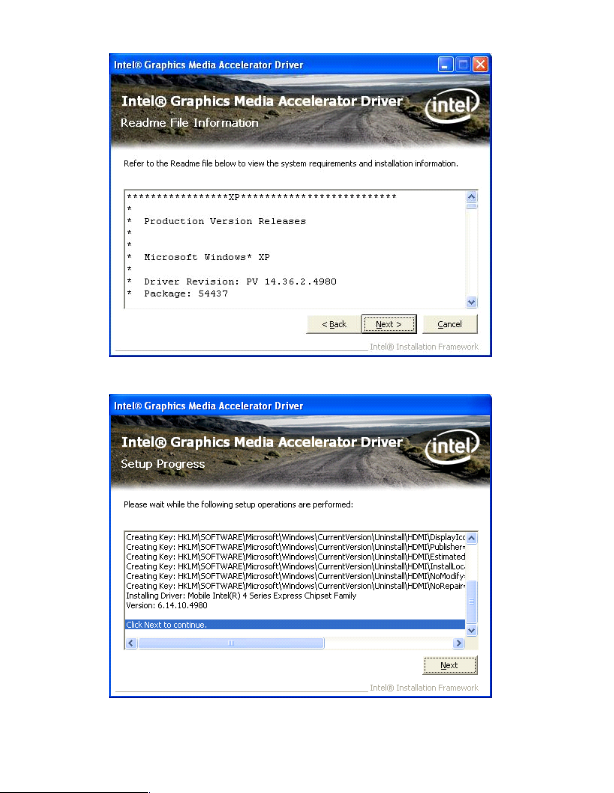
4.2 Graphics Media Accelerator driver
To install the VGA drivers, follow th e steps below to proceed with the installation.
Step 1.Select VGA Chipset Driver.
Step 2. Click Next to continue.
Page 55

Step 3. Click Next to continue s etup program.
Step 4. Read the lic ense agreement. Clic k Yes to accept all of the terms of the license agreement.
Page 56
Step 5. Clic k Next.
Step 6. Clic k Next to continue.
Page 57

Step 7 . Selec t Yes, I w ant to restart this computer now . Click Finish to complete installation.
4.3 Network Adapter
To install the N etwork Adapter device driver, please follow the steps below.
Step 1. Select Network Adapter.
Page 58

Step 2. Click Next to continue.
Step 3. Read the license agreement. Select I accept the terms in the license agreement then click
Next to continue.
Page 59

Step 4. Select Drivers, PROSet for Windows* Device Manager, Advanced Network
Services. Click Next to continue.
Step 5. Click Install to begin the insta llation.
Page 60

Step 6. Click Finish to complete the installation.
4.4 Realtek ALC662 HD Audio Codec Driver Installation
To install the Realtek ALC662 HD Audio Codec Driver, please f ollow the steps below.
Step 1. Select Realtek AL662 Audio Codec Driver from the list
Page 61

Step 2. Click Next to continue.
Step 3. Click Yes , I want to res tart my computer now. Click Finish to complete the in stallation.
Page 62

Chapter 5 Touch Screen Installation
This chapter describes how to install drivers a nd other software that will al low your PenMount 6000
Controller Board to w ork with different operating system s.
NOTE: PenMou nt USB drivers support up to 15 USB controllers.
5.1 Introduction to Touch Screen Controller Board
PenMount 6300 USB control board is a touch screen control board designed for USB interface an d
specific for 4, 5, 8-wire touch screens. It is designed with USB interface features with multiple devices
supporting function. PenMount 6300 control board using PenMount 6000 controller that has been
designed for those who may like and all-in-one solution with 10-bit A/D converter built-in to make the
tota l printed circuit b oard dense r, circuit diagram also designed for 12-bit ADC f or optional. There are
two connectors on this board, one connector is for 4, 5, 8-wire touch screen cable (optional), and
ano ther is for 4-pin USB A type cable (optional).
Figure 5.1: Bird?s Eye View of Control Board
5.2 Windows 2000/XP/2003/Vista Universal Driver Installation
for PenMount 6000 Series
Before installing the Windows 2000/XP driver software, you must have the Windows 2000/XP system
installed and running on your computer. You must also have one of the following PenMount 6000
series controller or control boards installed: PM6500, PM6300.
Page 63

PCH3591/3791/3991
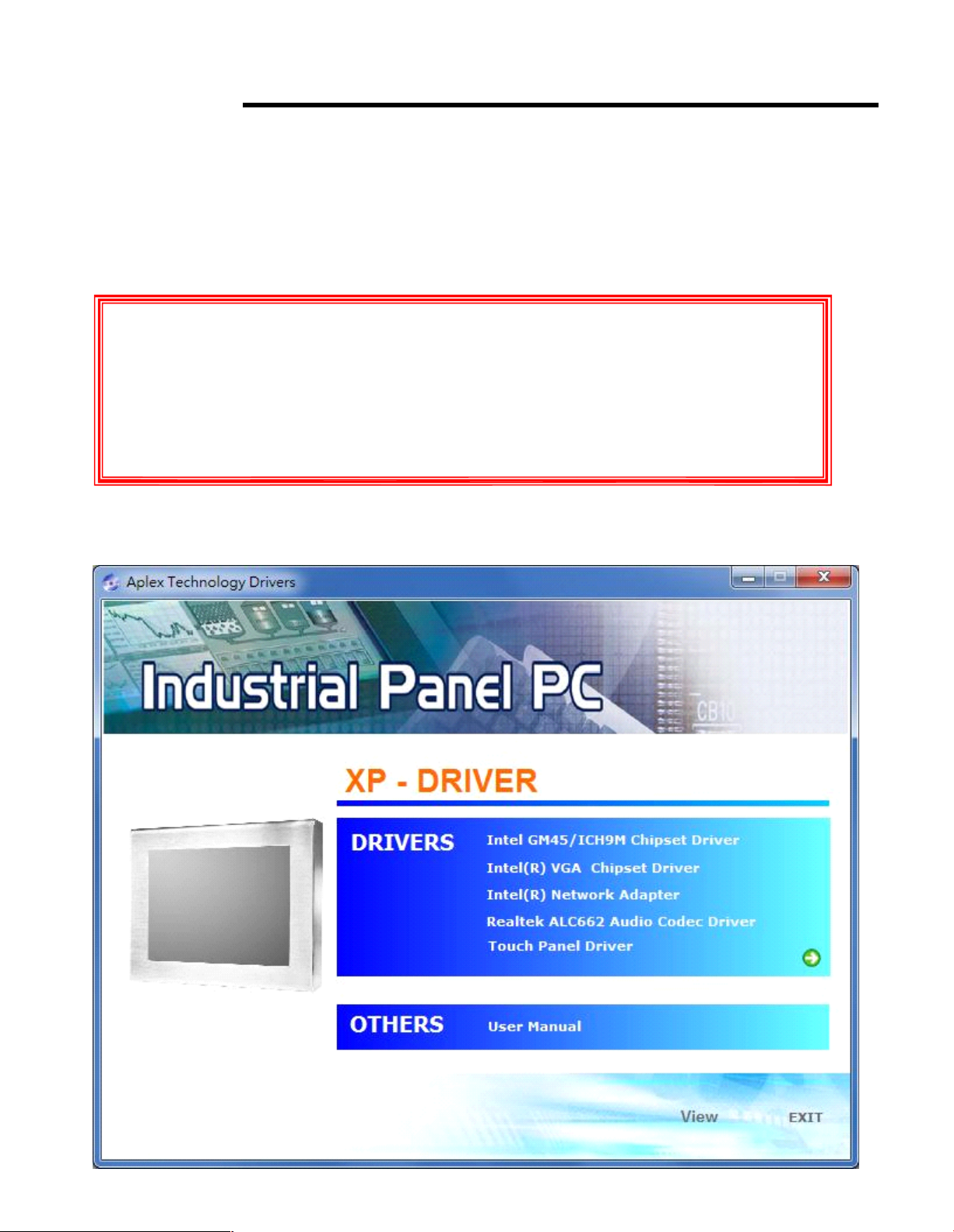
5.2.1 Installing Software
If you have an older version of the PenMount Windows 2000/XP driver installed in your system, please
remove it first. Follow the steps below to install th e PenMount D MC6000 W indows 2000/XP driver.
Step 1. Insert the product CD, the screen below would appear. Click touch panel driver.
15/17/19 inch Fanless Panel PC
14628 Ce ntral Ave,
Chino , CA 91710
tel:909.597.7 588, fax:909.597.1939
© Copyright 2013 Acnodes, Inc.
All righ ts reserved. Product descripti on and product speci ficat ions
are subj ect to change w ith out n oti ce. F or lates t product inform ati on,
ple ase vis it Acnod es’ we b site at www.ac nodes.c om.
Page 64

Step 2. Click Next to continue.
Step 3. Read the license agreement. Click I Agree to agree the license agreemen t.
Page 65

Step 4. Choose the folder in which to install PenMount Windows U niversal D river. Click Install to
start the installatio n.
Step 5. Wait for installation. Then click Next to contin ue.
Page 66

Step 6. Clic k OK.
Step 7. Clic k Finish to comp lete installation.
Page 67

5.2.2 Software Functions
Upon rebooting, the computer automatically finds th e new 6000 controller board. The touch screen is
con nected but not calibrated. Follow the procedures below to carry out calibratio n.
1. After installation, click the Pe nMou nt Monitor icon “ PM” in the menu bar.
2. W hen the PenMount Control Panel appears, select a device to “ Calibrate.”
PenMount Control Panel
The functions of the PenMount Control Panel are D evice, Multiple Monitors ,Tools and About,
which are explained in the following sections.
Device
In this window, you can find out that how many devices be detected on your sys tem.
Calibrate
This fu nction offers two wa ys to calibrate your touch screen. „ Standard Calibration?adjusts mos t
touch screens. „ Advanced Calibratio n?adjusts aging touch screens.
Standard Calibration Click this button and arrows appea r
pointing to red squares. Use your finger or
stylus to touch the red squares in
sequence. After the fifth red point
calibration is complete. To skip, press
ESC
Page 68

Advance d Calibratio n
Advanced Calibration uses 4, 9, 16 or 25
points to effectively calibrate touch panel
linearity of aged touch scree ns. C lick this
button and touch the red squares in
sequence with a stylus. To skip, press
ESC ? .
Command C alibration
Command call calibration function. U se
comm and mode call calibration function,
this can uses Standard, 4, 9, 16 or 25
points to calibrate E.g. Please run ms-dos
prompt or command prompt c:\Program
Files\PenMount Universa Drive r\Dmcctrl.e xe
-calibration 0 ( Standard Ca libration)
Dmcctrl.exe - calibration ($) 0= Stan dard
Calibration 4=Advanced Calibration 4
9=Advanced Calibration 9 16=Advanced
Calibration 16 25=Advanc ed Calibration 25
Step 1. Please select a devic e then click “ Configure” . You can also doub le click the device
too.
Page 69
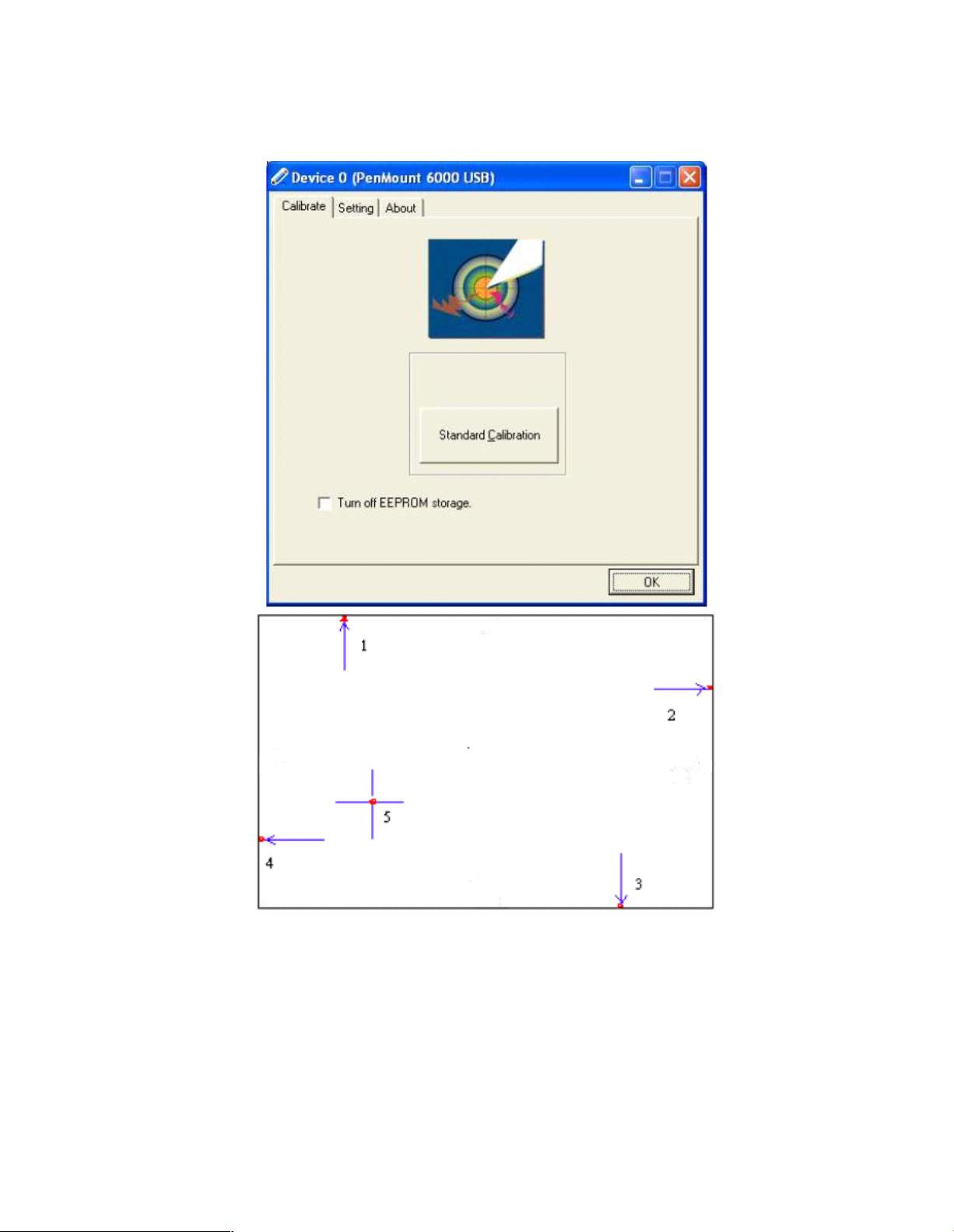
Step 2.Click “ Standard Calibration” to start calibration procedure
NOTE: The older the touch screen, the more Advance d Mode calibration p oints you need for an
accurate calibration. Use a stylus during Advanced Ca libration for greater accuracy. Please follow the
step as below:
Page 70

Step 3 .Come back to “ Pen Mount Control Panel” and select Tools then click
Advanced
Calibration.
Step 4. Select Device to calibrate, then you can start to do Advanced Calibration.
NOTE: Recommend to use a stylus during Ad vanced Calibration f or greater accuracy.
Page 71

Setting
Page 72

About
This panel disp lays information about the PenMount controller and driver version.
Page 73

Multiple Monitors
Multiple Monitors supports from two to six touch screen displays for one system. The PenMou nt
drivers f or W in dows 2000/XP su pport Multiple Monitors. This function supports from two to six touch
screen displays f or one system. Each monitor requires its own PenMou nt touch screen control board,
either installed inside the display or in a central unit. The PenMoun t control boards must be conne cted
to th e computer COM ports via the RS-232 interface. Driver installation proce dures are the same as
for a single monitor. Multiple Monitors supports the following modes:
Windows Extend Monitor Function
Matrox DualHead Multi-Screen Function
nVidia nView Function
NOTE: The Multiple Monitors function is for use with multiple displays only. D o not use this function if
you ha ve only one touch screen display. Please note once you turn on this function the Rotating
function is disabled.
Enable the multiple display function a s follows:
Step 1. Check the Multiple Monitor Support box; then click Map Touch Screens to assign touch
controllers to displays.
Page 74

Step 2. When the mapping screen message appears, click OK.
Step 3. Touch each screen as it displays Please touch this monitor. Press
„ S ?
to skip. Following
this sequence and touching each screen is called mapping the touch screens.
Step 4. After the setting procedure is finished, m ayb e you need to calibrate for each p anel and
controller
NOTES:
1. If you used a single VGA output for multiple m onitors, please do not use th e Multiple Monitors
function. Just follow the regular procedure for calibration on each of you r desktop monitors.
2. The R otating function is disabled if you use the Multiple Monitors function.
3. If you change the resolution of display or screen address, you have to redo Map Touch Screens so
Page 75

the system understands where the displays are.
4. If you more monitor mapping one touch screen, Please press
„ S ?
to skip mapping
step.
Tools
Draw
Tests or demonstrates the PenMount touch
screen operation.
Advanced Calibration
Enable Advanced Calibration function
Right Button Icon
Enable right button function. The icon can
show on D esktop or System Tray (menu bar).
Page 76

About
You can see how many devices of PenMount controller that are plugged to your syste m
PenMount Monitor Menu Ic on
The PenMount monitor icon (PM) appears in the menu bar of Windows 2000/XP system when you
turn on PenMount Monitor in PenMount Uti lities.
PenMount Monitor has the fo llowing function
Page 77

PenMount Rotating Functions
The PenMount driver for W indows 2000/XP supports several display rotating softw are pa ckages.
W indows Me/2000/XP support display rotating software packa ges such as:
• Portrait? s Pivot Screen Rotation Software
• ATI Display Driver Rotate Function
• nVidia Dis play Driver Rotate Function
• SMI Display Driver Rotate Function
• 845G/GE Display Driver Rotate Fun ction
Configuring the Rotate Function
1. Install the rotation software package.
2. C hoose the rotate function (0°, 90°, 180°, 270°) in the 3rd party software. The calibration screen
appears automatically. Touch this point and rotation is mapped.
NOTE: The R otate function is d isabled if you us e Monitor Mapping
 Loading...