

Page 1

PCH 3098
8 inch Atom Fanless Panel PC
© Copyrigh t 2012 Acnodes, Inc.
All rights reserved. Product description and product specifi cations
are subj ect to chan ge without notice . For latest produ ct in formati on,
please visit Acnodes’ we b site at www.acnodes.c om.
14628 Central Ave.
Chin o, CA91710
Tel:909.597.7588, Fax:909. 597.1939
PCH 3098
8 inch Atom Fanless Panel PC
User Manual
PCH3098: 8” Industrial Fanless Panel PC with Atom Z510
processor
Page 2

PCH 3098
8 inch Atom Fanless Panel PC
© Copyrigh t 2012 Acnodes, Inc.
All ri ghts reserved . Produ ct descri pti on an d produ ct specif icati ons
are subj ect to chan ge without noti ce. For latest product informati on,
please visit Acnodes’ we b site at www.acnodes.c om.
14628 Central Ave.
Chin o, CA91710
Tel:909.597.7588, Fax:909. 597.1939
PCH 3098
8 inch Atom Fanless Panel PC
Warning!
Safety & Warranty
1. Read these safety instructions carefully.
2. Keep this user's manual for later reference.
3. Disconnect this equipment from any outlet before cleaning. Do not use liquid or spray
detergents for clean ing. Use a damp cloth.
4. For pluggable equipment, the power outlet must be installed near the equipment and must be
easily accessible.
5. Keep this equipment away from humidity.
6. Put this equipment on a reliable surface during installation. Dropping it or letting it fall could
cause damage.
7. The openings on the enclosure are for air convection. Protect the equipment from overheating.
DO NOT COVER THE OPENINGS.
8. Make sure the voltage of the power source is correct before connecting the equipment to the
power outlet.
9. All cautions and warnings on the equipment should be noted.
10. If the equipment is not used for a long time, disconnect it from the power source to avoid
damage by transient over-voltage.
11. Never pour any liquid into an opening. This could cause fire or electrical shock.
12. NEVER OPEN THE EQUIPMENT. FOR SAFETY REASONS, ONLY QUALIFIED SERVICE
PERSONNEL SHOULD OPEN THE EQUIPMENT.
13. If any of the following situations arises, get the equipment checked by service personnel:
The power cord or plug is damaged.
Liquid has penetrated into the equipment.
The equipment has been exposed to moisture.
The equipment does not work well, or you cannot get it to work according to the users manual.
The equipment has been dropped and damaged.
Page 3

© Copyrigh t 2012 Acnodes, Inc.
All rights reserved. Product description and product specifi cations
are subj ect to chan ge without notice . For latest produ ct in formati on,
please visit Acnodes’ we b site at www.acnodes.c om.
14628 Central Ave.
Chin o, CA91710
Tel:909.597.7588, Fax:909. 597.1939
PCH 3098
8 inch Atom Fanless Panel PC
T h e e q u ip m e n t h a s o b vio u s sig n s o f b re a ka g e .
1 4 . D O N O T L EA VE T H IS EQ U IP ME N T IN AN E N V IR O N M E N T W H ER E T H E S T O R A G E
T E MP E R A T U R E IS B EL O W - 2 0 ° C O R AB O VE 7 0 ° C . IT M AY D A M AG E T H E EQ U IPM E N T .
T h i s e q u ip m e n t g e n e r a te s u se s a n d ca n ra d ia te ra d i o fre q u e n c y e n e rg y a n d if n o t in s ta lle d a nd
u s e d in a c co r d a n ce w ith th e in str u cti o n s m a n u a l, it m a y ca u s e in te rf e re n c e to ra d i o
c o m m u n ica tio n s.
It h a s b e e n te ste d a n d fo u n d to c om p ly w ith th e lim its fo r a C la s s A co m p u tin g d e vic e p u r su a n t to
F C C R u l e s, w h ic h a re d e s ig n e d to p r o vid e r e a so n a b le p r o te
ctio
n a g a i n st su ch i n te rfe r e n ce w h e n
o p e ra te d i n a co m m e rc ia l e n vir o n m e n t. O p e ra ti o n of th is e q u ip m e n t in a r e sid e n ti a l a r e a is lik e ly
to c a u se in te r fe re n c e in w h ich ca se th e u se r a t h is o w n e x p e n se w ill b e re q u ir e d to ta ke w h a te ve r
m e a su re s m a y b e r e q u ir e d to co r r e ct th e in te r fe r e n ce .
El e ctr ic S h o ck H a za r d – D o n o t o p e r a te th e m a ch in e w ith its b a ck co ve r r e m o ve d . T h e r e a r e
d a n g e r o u s h ig h vo lta g e s in sid e .
D i sc la im e r
T h is in f or m a t ion in this d o c um e n t is subject to change w ith o u t n o t ic e . In n o e ve n t s h a ll
Acnodes Corporation b e liable f o r d am a g e s o f a n y k in d , w h e t he r in c id e n ta l or c o n s e q ue n t ia l, a ris in g
f ro m e it h e r t h e u s e o r m is us e of in f o rm a t io n in th is d o c u m e nt o r in a n y re la t e d m a t e r ia ls .
Page 4

© Copyrigh t 2012 Acnodes, Inc.
All ri ghts reserved . Produ ct descri pti on an d produ ct specif icati ons
are subj ect to chan ge without noti ce. For latest product informati on,
please visit Acnodes’ we b site at www.acnodes.c om.
14628 Central Ave.
Chin o, CA91710
Tel:909.597.7588, Fax:909. 597.1939
PCH 3098
8 inch Atom Fanless Panel PC
Table of Con tents
Warning!…………… ……………………………………………………………….……..….2
Disclaimer………………………………………………………………….…………………2
Chapter 1 Getting Started
1.1 Sp
1.2 D
1.3 Brief D
ec ific a tio ns … …
im ens ions … …
esc rip tio n… …
… … … … … … … … … … … … …
… … … … … … … … … …
...…
… … … … … … … … … … … … … … … … … …
.… … …
… … … … …
… … … … … … … … …
.… … 11
.......8
Chapter 2 Hardware
2.1 M
2.2 Jumpers and Connectors
2.3 Jumpers Setting and C
ain boa
rd … … … … …
… ..… … .…
… … … … … … … … … … … … …
Loc ation … … … … …
onne cto
rs … … … … …
..… ..12
… … … … … … … … …
...… …
… … … … … … … 14
...13
Chapter 3 BIOS Setup
3.1 Operations after POST
S c
reen..........................................................26
..6
3.2 BIOS SETUP U
3.3 System O v
erv iew
3.4 Advanced Settings............................................................................... 29
3.5 Advanced PCI/PnP Settings................................................................ 3 8
3.6 Boot Settings....................................................................................... 41
3.7 Security Settings.................................................................................. 43
3.8 Advanced Chipset Settings................................................................... 44
3.9 Exit O
ption s…
… … … … … … … … … … … …
Chapter 4 Installation of Drivers
4.1 Intel Chipset D
4.2 Intel Graphics Media Accelerator D
4.3 Intel 8257L Gbe LAN Device D
4.4 Realtek HD Audio Driver
TILIT
Y..........................................................................27
..................................................................................28
rive r.…
...… … …
… … … … … … … … …
rive r...… … … …
riv er… …
… … … … … … … … … … …
Installation… … .… …
...… … …
… … … … … … … … .51
… … … … … … … 53
… …
… ..… … … … ..57
.… .60
… …
..…
… … … … … … 63
Page 5

© Copyrigh t 2012 Acnodes, Inc.
All rights reserved. Product description and product specifi cations
are subj ect to chan ge without notice . For latest produ ct in formati on,
please visit Acnodes’ we b site at www.acnodes.c om.
14628 Central Ave.
Chin o, CA91710
Tel:909.597.7588, Fax:909. 597.1939
PCH 3098
8 inch Atom Fanless Panel PC
Chapter 5 Touch Screen Installation
5.1 Introduction to Controller
B oard..… … … … …
… … … … … …
.… … …
… … 65
5.2 Windows 2000/XP USB Driver
In sta llation…
… … … … … …
Figures
Figure 1.1: PCH 3098
Figure 1.2: PCH 3298 Dimensions……………………..……………………..9
Figure 1.3: PCH 3598 Dimensions…………………….…………………….10
Figure 1.4: Front View ………………………………………………………….11
Figure 1.5: Rear View…………………………………………………………...11
Figure 2.1: Mainboard Overview………………………………………….....12
Figure 5.1 Birdeye’s View of Control Board………………..…………………65
Dim ens
io
ns… …
… … … … … … … … … … … … …
..…
.… … … ..…
....8
.66
Page 6
PCH 3098
8 inch Atom Fanless Panel PC
© Copyrigh t 2012 Acnodes, Inc.
All ri ghts reserved . Produ ct descri pti on an d produ ct specif icati ons
are subj ect to chan ge without noti ce. For latest product informati on,
please visit Acnodes’ we b site at www.acnodes.c om.
14628 Central Ave.
Chin o, CA91710
Tel:909.597.7588, Fax:909. 597.1939
Specs
PCH 309 8
PCH 329 8
PCH359 8
CPU
Atom Z510p 1.1 GHz FSB 400 MHz, Z 530p 1.6 GHz FSB 533 MHz for option
Chipset
US15WP
System Memory
O n board 1 G B DDR2 400 MHz
Graphic
Integrated Graphics GMA500
External I/O Port
2 x USB 2.0 ports
2 x RJ-45 LAN ports
1 x DB-9 RS-232
(CO M1) and RS-422/485
1 x DC power input
2 x USB 2.0 ports
2 x RJ-45 LAN ports
1 x DB-9 RS-232 (CO M1)
1 x DB-9, CO M2
(RS-232/422/485
connector, default
RS-232)
1 x DC power input
Standard I/O
2 x USB 2.0 ports
2 x RJ-45 LAN ports
1 x DB-9 RS-232 (COM1)
Connector
1 x DB-9, CO M2
(RS -232/422/485
connector, default
RS-232)
1 x DC power input
O ption
1 x VG A DB-15 port
1 x Audio Line-out port
Display Type
8” TFT-LCD
12” TFT-LCD
15” TFT-LCD
Max. Resolution
800 x 600
800 x 600
1024 x 768
Maximum Colors
262K
262K
16.2M
Viewing Angle (Degree)
H:130/ V:110
H:140/V:110
H:160/V:130
Chapter 1 System
1.1 Specifications
Page 7
PCH 3098
8 inch Atom Fanless Panel PC
© Copyrigh t 2012 Acnodes, Inc.
All rights reserved. Product description and product specifications
are subj ect to chan ge without notice . For latest produ ct in formati on,
please visit Acnodes’ we b site at www.acnodes.c om.
14628 Central Ave.
Chin o, CA91710
Tel:909.597.7588, Fax:909. 597.1939
Luminance (cd/m²)
350
Backlight Lifetime
50,000
Rating
IP65
Touch Screen Type
Resistive
Storage
1 x 2.5”
Wireless LAN
Wireless
Power Supply
DC 9-32V
Construction and Color
Stainless
Dimensions (WxHxD)
250 x 209 x 65 mm
335 x 269 x 65 mm
399 x 328 x 65 mm
Operating Temperature
0~50
Storage Temperature
-20~60
Relative Humidity
10%~90%@ 40 ゚ C, (non-condensing)
Certificate
CE/FCC Class A
Page 8
PCH 3098
8 inch Atom Fanless Panel PC
© Copyrigh t 2012 Acnodes, Inc.
All ri ghts reserved . Produ ct descri pti on an d produ ct specif icati ons
are subj ect to chan ge without noti ce. For latest product informati on,
please visit Acnodes’ we b site at www.acnodes.c om.
14628 Central Ave.
Chin o, CA91710
Tel:909.597.7588, Fax:909. 597.1939
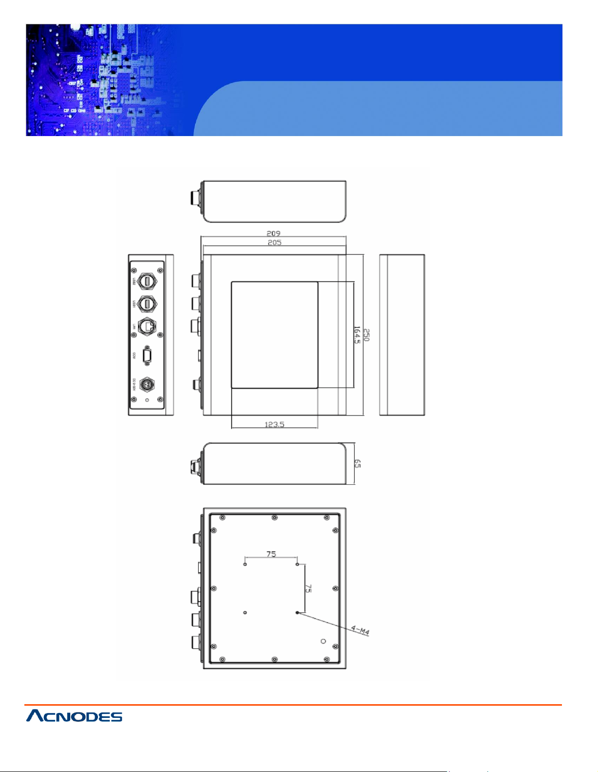
1 .2 D im e n s
io
n s
Figur
e 1 .1 : D im e nsions o f th e P C H 309 8
Page 9
© Copyrigh t 2012 Acnodes, Inc.
All rights reserved. Product description and product specifications
are subj ect to chan ge without notice . For latest produ ct in formati on,
please visit Acnodes’ we b site at www.acnodes.c om.
14628 Central Ave.
Chin o, CA91710
Tel:909.597.7588, Fax:909. 597.1939
PCH 3098
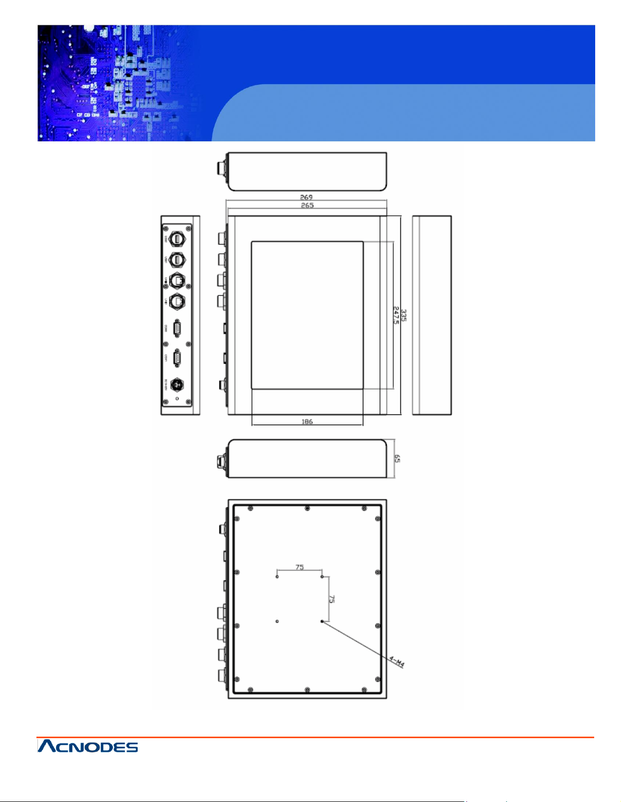
Figure 1.2: Dimensions of the PCH3298
8 inch Atom Fanless Panel PC
Page 10
© Copyrigh t 2012 Acnodes, Inc.
All ri ghts reserved . Produ ct descri pti on an d produ ct specif icati ons
are subj ect to chan ge without noti ce. For latest product informati on,
please visit Acnodes’ we b site at www.acnodes.c om.
14628 Central Ave.
Chin o, CA91710
Tel:909.597.7588, Fax:909. 597.1939
PCH 3098
8 inch Atom Fanless Panel PC
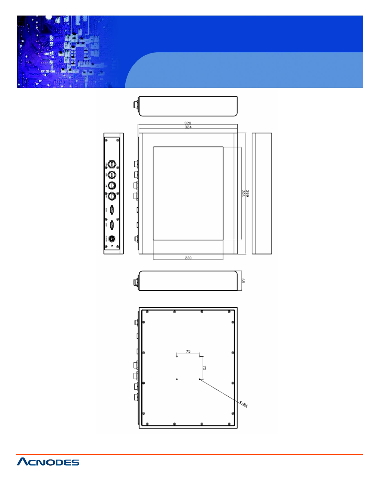
Figure 1.3: Dimensions of the PCH3598
Page 11
© Copyrigh t 2012 Acnodes, Inc.
All rights reserved. Product description and product specifications
are subj ect to chan ge without notice . For latest produ ct in formati on,
please visit Acnodes’ we b site at www.acnodes.c om.
14628 Central Ave.
Chin o, CA91710
Tel:909.597.7588, Fax:909. 597.1939
PCH 3098
8 inch Atom Fanless Panel PC
1.3 Brief Description of the PCH3098/3298/3598
The PC H-3098/3298/3598 is a f anless des ign panel PC , whic h comes with an 8-inch (luminance of
3 50 cd/m²)/12-inch (luminance of 350 cd/m²)/1 5-in ch (luminance of 350 cd/m²) TFT LC D. It is pow ere d
b y an Atom Z510p Processor. The indus trial panel PC also features two CO M po rts, tw o USB 2. 0
p orts, one 2.5” HD D, one CF slot, DC power of 9~32V, etc. It is ideal for use as a PC-based c ontroller
fo r Indu stria l Automation & Factory Automation.
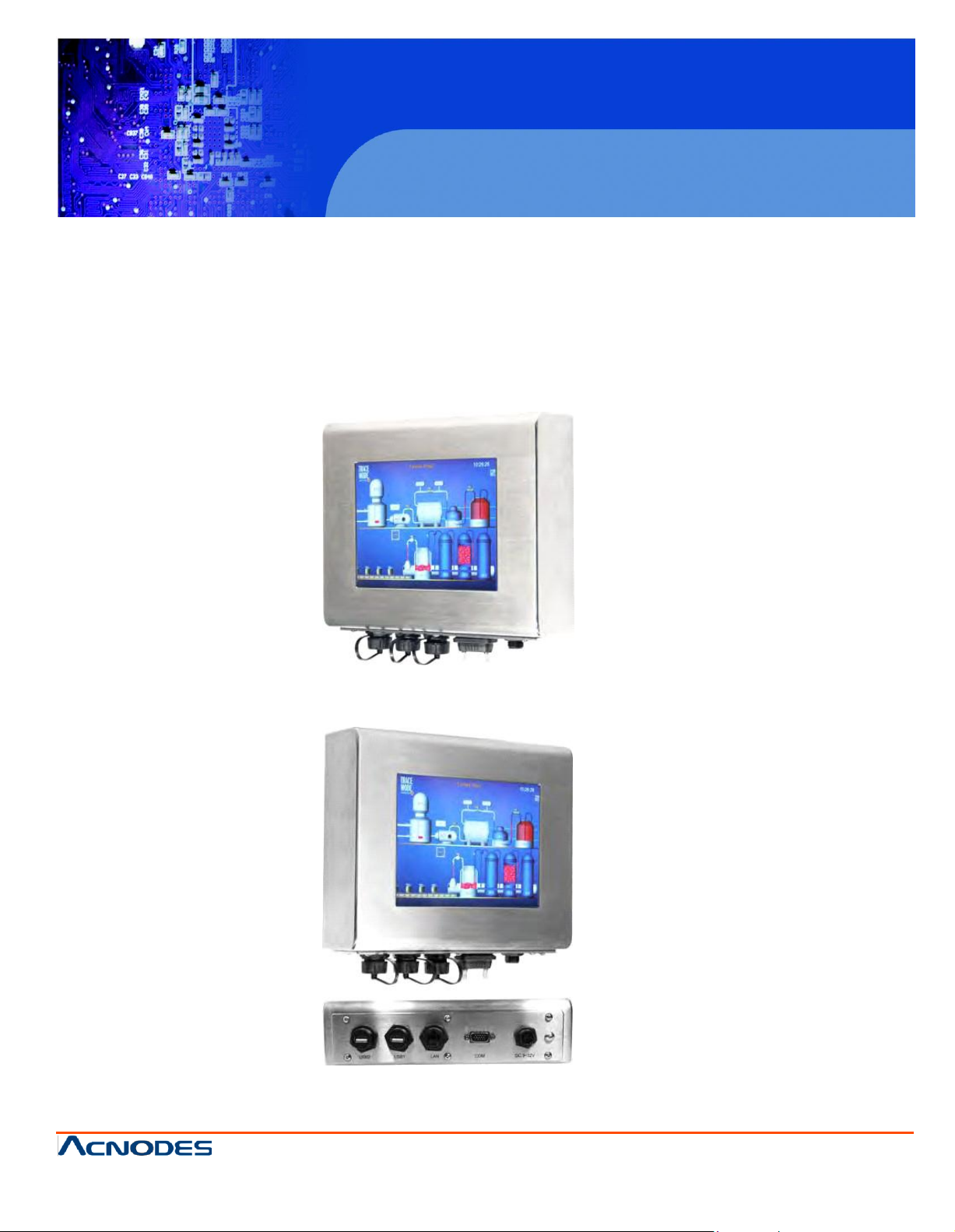
Figure 1.4: Front View of PCH3098
Figure 1.5: Rear View of PCH3098
Page 12
© Copyrigh t 2012 Acnodes, Inc.
All ri ghts reserved . Produ ct descri pti on an d produ ct specif icati ons
are subj ect to chan ge without noti ce. For latest product informati on,
please visit Acnodes’ we b site at www.acnodes.c om.
14628 Central Ave.
Chin o, CA91710
Tel:909.597.7588, Fax:909. 597.1939
PCH 3098
8 inch Atom Fanless Panel PC
Chapter 2 Hardware
2.1 Mainboard
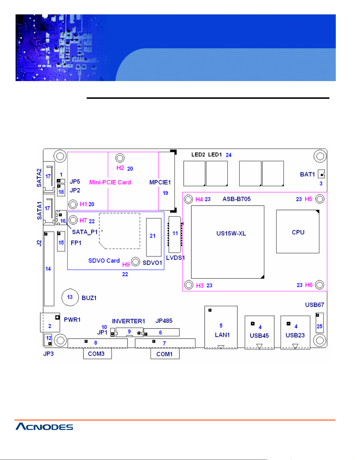
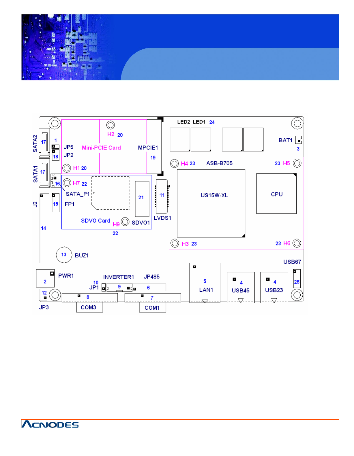
Figure 2.1: Mainboard Overview
Page 13
© Copyrigh t 2012 Acnodes, Inc.
All rights reserved. Product description and product specifications
are subj ect to chan ge without notice . For latest produ ct in formati on,
please visit Acnodes’ we b site at www.acnodes.c om.
14628 Central Ave.
Chin o, CA91710
Tel:909.597.7588, Fax:909. 597.1939
PCH 3098
8 inch Atom Fanless Panel PC
2.2 Jumpers and Connectors Location
Page 14
PCH 3098
8 inch Atom Fanless Panel PC
© Copyrigh t 2012 Acnodes, Inc.
All ri ghts reserved . Produ ct descri pti on an d produ ct specif icati ons
are subj ect to chan ge without noti ce. For latest product informati on,
please visit Acnodes’ we b site at www.acnodes.c om.
14628 Central Ave.
Chin o, CA91710
Tel:909.597.7588, Fax:909. 597.1939
JP5
Mode
Open
ATX Power Mode
Close
AT Power Mode
Pin#
Signal Name
1
+DC9V~DC30V
2
Ground
Pin#
Signal Name
Pin1
VBAT
PIN2
Ground
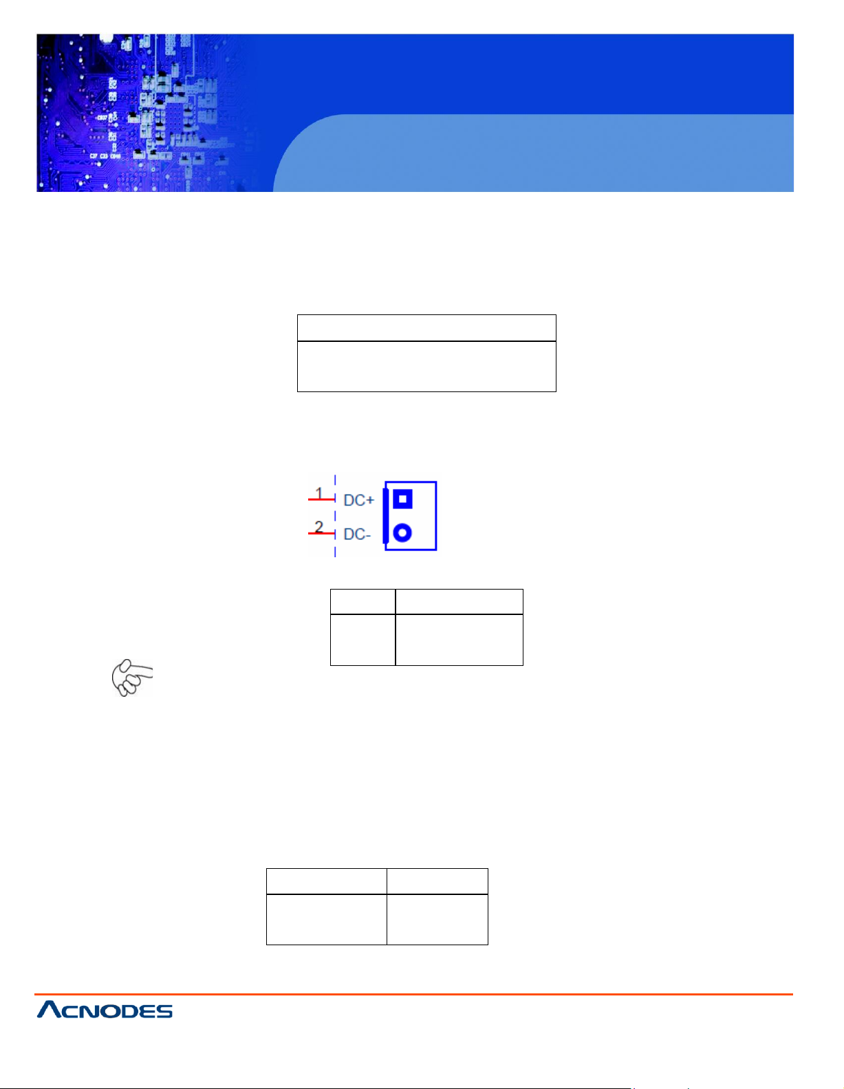
2.3 Jumpers Setting and Connectors
1. JP5: (2.0mm Pitch 1X2 Pin Header), ATX Power and AT Power setting jumper.
2. PW R1 : (5.0mm 1x2 Pin Connector),DC9V~30V System power input connector
Note:
Make sure that the voltage of power supply is DC9V~30V before power on, or it may
cause boot up failure and even system damage.
3. BAT1: (1.25mm Pitch 1X2 box Pin Header) 3.0V Li battery is embedded to provide
power for
CMOS.
Page 15
PCH 3098
8 inch Atom Fanless Panel PC
© Copyrigh t 2012 Acnodes, Inc.
All rights reserved. Product description and product specifications
are subj ect to chan ge without notice . For latest produ ct in formati on,
please visit Acnodes’ we b site at www.acnodes.c om.
14628 Central Ave.
Chin o, CA91710
Tel:909.597.7588, Fax:909. 597.1939
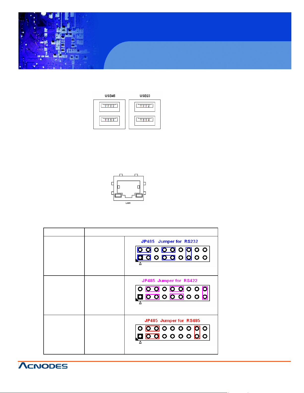
COM
1 M ode
JP 485 S
etting
RS232
(default)
1-3 ( C los e)
2-4 ( C los e)
7-9 ( C los e)
8-10 ( Clo se )
13-14 (Clo se)
RS 422
3-5 ( C los e)
4-6 ( C los e)
9-11 ( C los e)
10 -12 ( Clos e)
17 -18 (C lose )
RS 485
3-5 ( C los e)
4-6 ( C los e)
15 -16 (C lose )
4 . U SB23 /USB 45: (Double s tack USB type A), Rear USB c onnector, it pro vides u p to 4 US B2.0
speed u p to
480M
b/s.
ports
,
5. L AN1 : (RJ45
prov
ided. Used Intel 82574L chipset ,LINK LED (green) and
loca ted at the left-hand and
s tate of LAN .
Connector
),
Rear LAN port, 1 standard 10
right-
hand side of th e Ethernet p ort indicate the
6 . JP 485 :
of COM1 port of RS232 or R S422 or RS 485 m ode.
(2.0m
m P itch 2x9 P in Header), COM1 setting jumper, pin 1~18 are used to sele ct signal out
/100/10
00M R J-45 Ethernet ports are
ACTIV
E LED (yellow) r espectively
activ
ity and
trans
mission
Page 16
PCH 3098
8 inch Atom Fanless Panel PC
© Copyrigh t 2012 Acnodes, Inc.
All ri ghts reserved . Produ ct descri pti on an d produ ct specif icati ons
are subj ect to chan ge without noti ce. For latest product informati on,
please visit Acnodes’ we b site at www.acnodes.c om.
14628 Central Ave.
Chin o, CA91710
Tel:909.597.7588, Fax:909. 597.1939
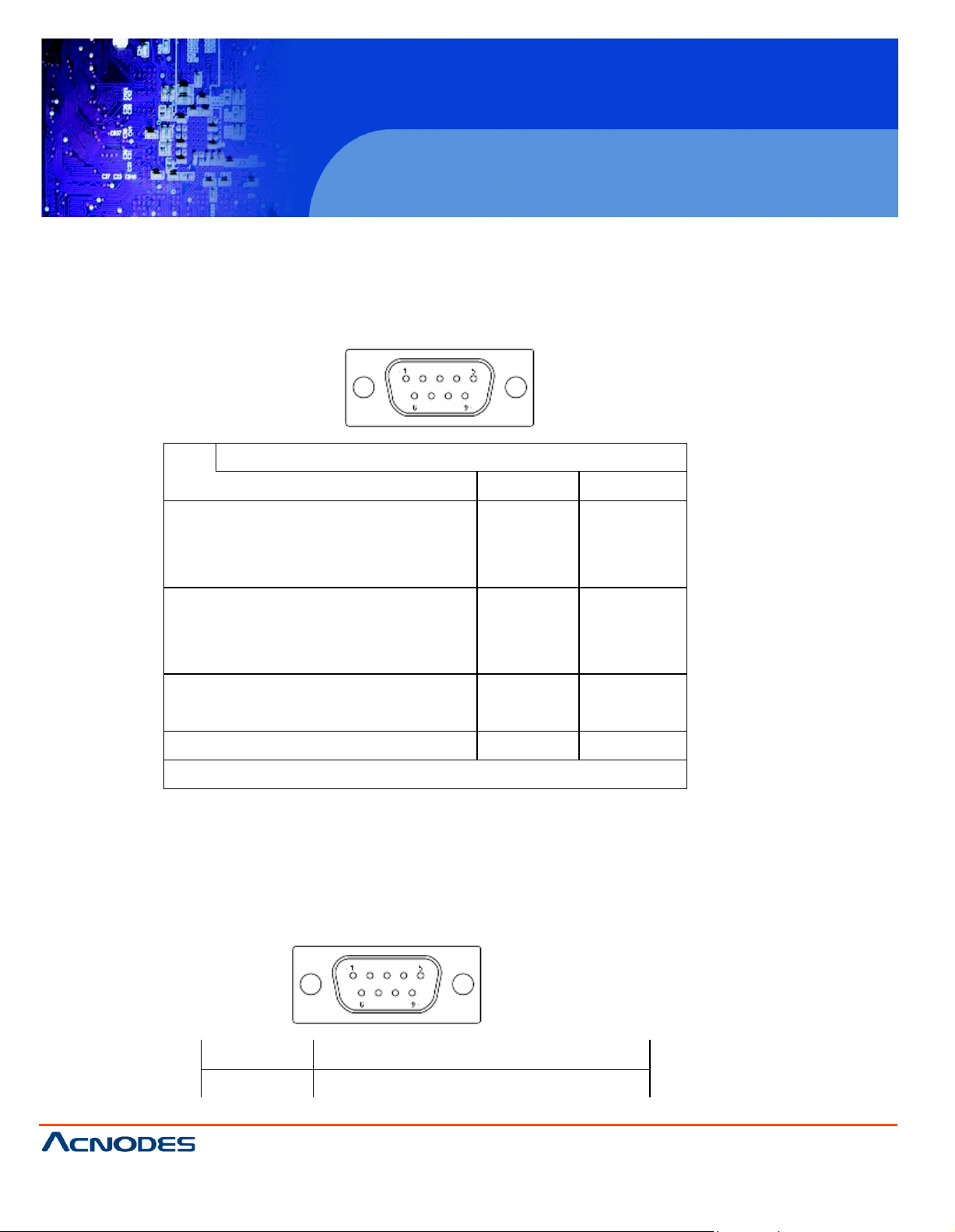
Pin#
Signal Name
RS232
RS422
RS485
1
DCD# (Data Carrier Detect)
422_TX-
485_D-
2
RXD (Received Data)
422_RX-
NC
3
TXD (Transmit Data)
422_RX+
NC
4
DTR (Data Terminal Ready)
422_TX+
485_D+
5
Ground
Ground
Ground
6
DSR (Data Set Ready)
NC
NC
7
RTS (Request To Send)
NC
NC
8
CTS (Clear To Send)
NC
NC
9
RI (Ring Indicator)
NC
NC
please refer to description of JP485
Pin#
Signal Name
1
DCD# (Data Carrier Detect)
7. COM 1: (Type DB9), Rear serial port, standard DB9 serial port is provided to make a direct
connection to serial devices. COM1 port is controlled by pins No.1~18 of JP485, select output
Signal RS232 or RS422 or RS485, for details, please refer to description of JP485.
8. COM 3: (Typ e D B9), Rear serial port, standard DB9 serial port is provided to make a direct
connection to serial devices. COM1 port is controlled by pins No.1~6 of JP3 select output Signal RI
or 5V or 12v, for details, please refer to description of JP3.
Page 17
PCH 3098
8 inch Atom Fanless Panel PC
© Copyrigh t 2012 Acnodes, Inc.
All rights reserved. Product description and product specifications
are subj ect to chan ge without notice . For latest produ ct in formati on,
please visit Acnodes’ we b site at www.acnodes.c om.
14628 Central Ave.
Chin o, CA91710
Tel:909.597.7588, Fax:909. 597.1939
2
RXD (Received Data)
3
TXD (Transmit Data)
4
DTR (Data Terminal Ready)
5
Ground
6
DSR (Data Set Ready)
7
RTS (Request To Send)
8
CTS (Clear To Send)
9
JP3 Setting:
Pin1-2 : RI (Ring Indicator) (default)
Pin3-4 : 5V Standby power (option)
Pin5-6: 12V Standby power (option)
JP3 Pin#
Function
Close 1-2
RI (Ring Indicator) (default)
Close 3-4
COM1 Pin9=+5V (option)
Close 5-6
COM1 Pin9=+12V (option)
Signal Name
JP1
PWM
Open
DC voltage Mode
Close
9 . JP3: (2.0mm Pitch 2x3 Pin Header), COM1 setting jumper, pin 1~6 are used to select signal out of
pin 9 of COM3 port.
1 0. JP1: (2.0mm Pitch 1x2 Pin Header), Backlight Control jumper setting for LVDS1.
Note:
Please check first your LVDS panel backlight control by DC voltage Mode or PWM?
Panel backlight control by Level 5V.
Page 18
PCH 3098
8 inch Atom Fanless Panel PC
© Copyrigh t 2012 Acnodes, Inc.
All ri ghts reserved . Produ ct descri pti on an d produ ct specif icati ons
are subj ect to chan ge without noti ce. For latest product informati on,
please visit Acnodes’ we b site at www.acnodes.c om.
14628 Central Ave.
Chin o, CA91710
Tel:909.597.7588, Fax:909. 597.1939
Pin#
Signal Name
1
DC+12V
2
DC+12V
3
Ground
4
Ground
5
BKLT_EN
6
BKLT_CTRL
Signal Name
Pin#
Pin#
Signal Name
VCC 2 1
VCC
Ground
4
3
Ground
LA_DATAP0
6
5
LA_DATAN0
LA_DATAP1
8
7
LA_DATAN1
LA_DATAP2
10
9
LA_DATAN2
LA_DATAP3
12
11
LA_DATAN3
LA_CLKP
14
13
LA_CLKN
Ground
16
15
Ground
BKLT_EN_OUT
18
17
BKLT_CTRL
12V
20
19
12V
11. INVERTER1: (2.0mm Pitch 1x6 box Pin Header), Backlight control connector for LVDS1.
Note:
Pin6 is backlight control signal, support DC or PWM mode, mode select at BIOS CMOS menu.
1 2. LVD S1: For 18/24 bit LVDS output connector, fully supported by Intel US15W chipset, the
interface features dual channel 18/24-bit output. Model name of the interface connector is Hirose
DF13-40DP-1.25V.
13 . BU Z1: onboard buzzer.
Page 19

PCH 3098
8 inch Atom Fanless Panel PC
© Copyrigh t 2012 Acnodes, Inc.
All rights reserved. Product description and product specifications
are subj ect to chan ge without notice . For latest produ ct in formati on,
please visit Acnodes’ we b site at www.acnodes.c om.
14628 Central Ave.
Chin o, CA91710
Tel:909.597.7588, Fax:909. 597.1939
14. J2: (1.27 x 2.54mm Pitch 2x30 Pin Header), Can be connected to on e USB 2.0 Port and one PS/2
Keyboard port and one Mouse port and one Audio port and one SD bus and five GPIO and one SMB
bus and two RS232 Ports.
USB1:
·
Expansion USB connector, it provides two USB ports via a dedicated USB cable,
Speed up to 480Mb/s.
·
AUDIO:
Front Audio, An onboard Realtek ALC662 codec is used to provide high-quality audio I/O ports.
Line Out can be connected to a headphone or amplifier. Line In is used for the connection of
external audio source via a Line in cable. MIC is the port for microphone input audio.
·
PS/2:
Expansion PS/2 keyboard and mouse, the port can be connected to PS/2 keyboard and mouse via
a dedicated cable for direct used.
·
SD BUS:
Expansion SD bus.
·
GPIO:
Five GPIO, General-purpose input/output port, it provides a group of self-programming
interfaces to customers for flexible use.
·
SMB BUS:
Expansion SMB bus.
·
RS232(COM2,COM4):
Expansion serial ports are provided to make a direct connection to serial devices.
Page 20
PCH 3098
8 inch Atom Fanless Panel PC
© Copyrigh t 2012 Acnodes, Inc.
All ri ghts reserved . Produ ct descri pti on an d produ ct specif icati ons
are subj ect to chan ge without noti ce. For latest product informati on,
please visit Acnodes’ we b site at www.acnodes.c om.
14628 Central Ave.
Chin o, CA91710
Tel:909.597.7588, Fax:909. 597.1939
Function
Sign al Name
Pin#
Pin#
Signal Name
Functio
n
USB1
5V_USB
1 2 5V_USB
USB1
USB1_N
3 4 USB1_ P
Ground
5 6 Gro und
PS/2 MS
MS_CLK
7 8 MS_C LK
PS/2
KB
MS_DATA
9
10
KB_DATA
5V_F_AUDIO
11
12
GND _AUD
Audio
LINE_OUT_L
13
14
LINE_OUT_R
Audio
LINE_IN_L
15
16
LINE_IN_R
MIC_IN_L
17
18
MIC _IN_R
Ground
19
20
Gro und
SD bus
SD0_D2
21
22
SD0_D3
SD bus
SD0_CMD
23
24
SD0_D1
SD0_D0
25
26
D0_CLK
SD0_CD-
27
28
SD0_WP
3P3V_SD ISK
29
30
3P3V_SDISK
GPIO
EXT_GPIO6
31
32
EXT_GPIO9
GPIO
EXT_GPIO2
33
34
EXT_GPIOSUS0
EXT_GPIO3
35
36
EXT_GPIO8
EXT_GPIO1
37
38
EXT_GPIO4
RS232
(COM2)
Ground
39
40
Gro und
RS232
(COM2)
DSR2-
41
42
DCD2-
RTS2-
43
44
RXD2
CTS2-
45
46
TXD2
RI2-
47
48
DTR 2-
5V_S0
49
50
5V_S0
RS232
(COM4)
RS232
(COM4)
DSR4-
51
52
DCD4-
RTS4-
53
54
RXD4
CTS4-
55
56
TXD4
RI4-
57
58
DTR 4-
Ground
59
60
Gro und
Page 21
PCH 3098
8 inch Atom Fanless Panel PC
© Copyrigh t 2012 Acnodes, Inc.
All rights reserved. Product description and product specifications
are subj ect to chan ge without notice . For latest produ ct in formati on,
please visit Acnodes’ we b site at www.acnodes.c om.
14628 Central Ave.
Chin o, CA91710
Tel:909.597.7588, Fax:909. 597.1939
Signal Name
Pin#
Pin#
Signal Name
HD LED+
1
2
POWER LED+
HD LED-
3
4
POWER LED-
Ground
5
6
PWR_ON
RESET+
7
8
Ground
WAN LED-
9
10
WAN LED+
15. FP1 : (2.0mm Pitch 2X5 Pin Header), Front panel connector.
Pin1-3:
HDD LED, They are used to connect hard disk activity LED. The LED
blinks when the hard disk is reading or writing data.
Pin2-4:
POWER LED, They are used to connect power LED. When the system
is powered on or under S0/S1 state, the LED is normally on; when the
system is under S4/S5 state, the LED is off.
Pin5-6:
POWER on/off Button, They are used to connect power switch button.
The two pins are disconnected under normal condition. You may short
them temporarily to realize system startup & shutdown or awaken the
system from sleep state.
Pin7-8:
RESET Button, They are used to connect reset button. The two pins
are dis-connected under normal condition. You may short them
temporarily to realize system reset.
Pin9-10:
WAN LED, They are used to connect WAN LED.
Note:
When connecting LEDs, pay special attention to the signal polarity.
Make sure that the connector pins have a one-to-one
correspondence with cha ssis wiring, or it may cause boot up failure.
Page 22

PCH 3098
8 inch Atom Fanless Panel PC
© Copyrigh t 2012 Acnodes, Inc.
All ri ghts reserved . Produ ct descri pti on an d produ ct specif icati ons
are subj ect to chan ge without noti ce. For latest product informati on,
please visit Acnodes’ we b site at www.acnodes.c om.
14628 Central Ave.
Chin o, CA91710
Tel:909.597.7588, Fax:909. 597.1939
Pin#
Signal Name
1
+DC5V
2
Ground
JP2
Devices Master
1~2 on
3~4 off
5~6 off
CF Master
1~2 off
3~4 on
5~6 off
SATA1 Master
1~2 off
3~4 off
5~6 on
SATA2 Master
1 6. SA TA _P1 : (2.5mm Pitch 1x2 box Pin Header), an onboard 5V output connector is reserved to
provide power for SATA devices.
Note:
Output current of the connector must not be above 1A.
17 . SA TA 1/2: (SATA 7P),SATA1,SATA2 SATA Connectors, Two SATA connectors are
provided, with transfer speed up to 3.0Gb/s.
18. JP2: (2.0mm Pitch 2x3 Pin Header), SATA1/SATA2/CF Devices Master or slave jumper setting.
SATA1/ SATA2/ CF devices can only be used two at the same time, and the Master device can be
set one only. While using SATA1/SATA2 devices at the same time, one of the devices must be
set as Master.
Page 23
PCH 3098
8 inch Atom Fanless Panel PC
© Copyrigh t 2012 Acnodes, Inc.
All rights reserved. Product description and product specifications
are subj ect to chan ge without notice . For latest produ ct in formati on,
please visit Acnodes’ we b site at www.acnodes.c om.
14628 Central Ave.
Chin o, CA91710
Tel:909.597.7588, Fax:909. 597.1939
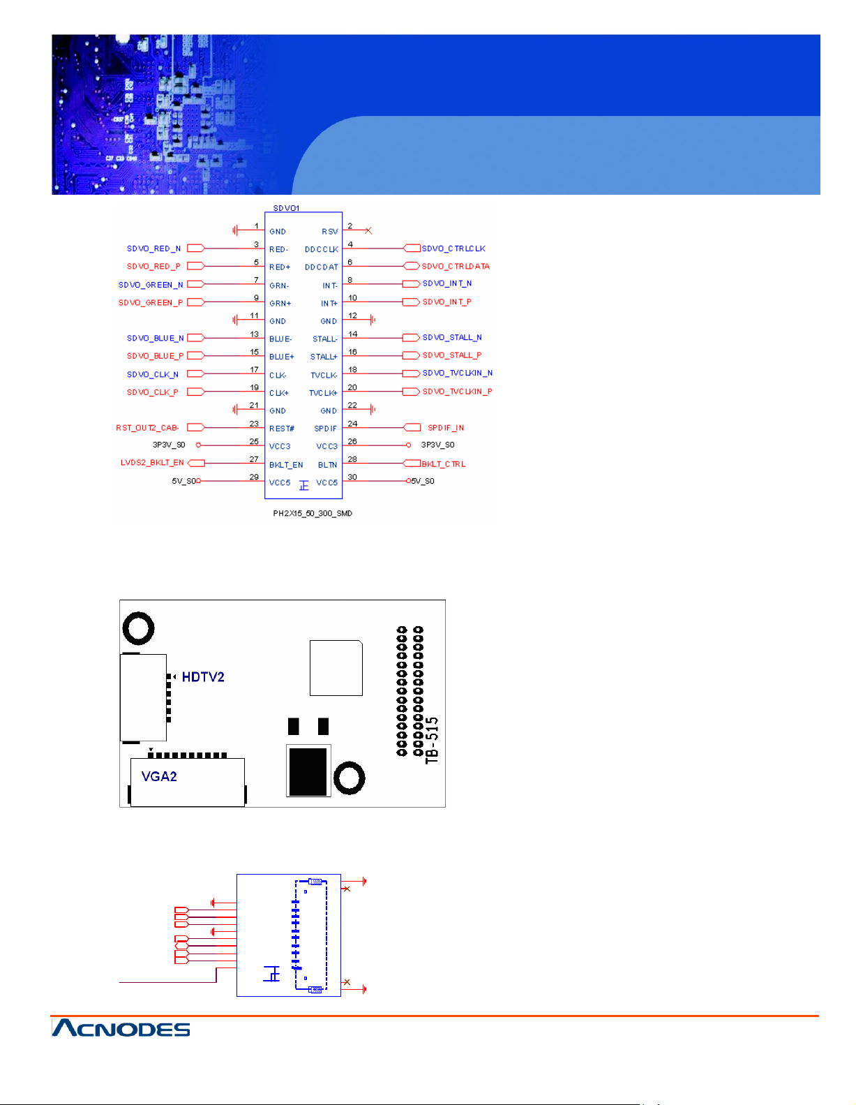
TB515 (option):
ASB-B705 SDVO1 connected Card, Support SDVO to CRT display and HDMI TV display
TB515 Location
VGA2 Port Signal Name:
C R T_GR EEN
CR T_D DC CLK
C RT_D DC D ATA
CR T_BLU E
CR T_R ED
C RT_ VSY N C
C VBS_SY NC _OU T
9
8
7
6
5
4
3
2
GND
BLUE
GREEN
R ED
GND
D DC C LK
D DC D ATA
VSYN C
RSV
VGA2
DF14A-10 P-1. 25H
G2
G2
N 2
N 2
10
1
N 1
N 1
G1
G1
Page 24
PCH 3098
8 inch Atom Fanless Panel PC
© Copyrigh t 2012 Acnodes, Inc.
All ri ghts reserved . Produ ct descri pti on an d produ ct specif icati ons
are subj ect to chan ge without noti ce. For latest product informati on,
please visit Acnodes’ we b site at www.acnodes.c om.
14628 Central Ave.
Chin o, CA91710
Tel:909.597.7588, Fax:909. 597.1939
2LB _D2_N
2LB _D 2_P
20
22
24
G ND
B _D 2B _D 2+
G ND
GN D
A _D 2A _D2+
GN D
19
21
23
2LA_ D2_N
2LA_ D2_P
2LB _C LK N
B _C LK-
A _CLK -
2LA_C LK N
2LB _C LK P
30
B _C LK+
G ND
A _C LK +
G ND
29
2LA _C LKP
2LDD C_ DA TA
32
34
D DC _D ATA
D D C_C LK
31
33
2LD DC _C LK
2LB _D 3_N
36
38
B _D 3-
A _D3-
35
37
2LA _D 3_N
G2
G1
G2
G1
N 2
N 1
N2
N1
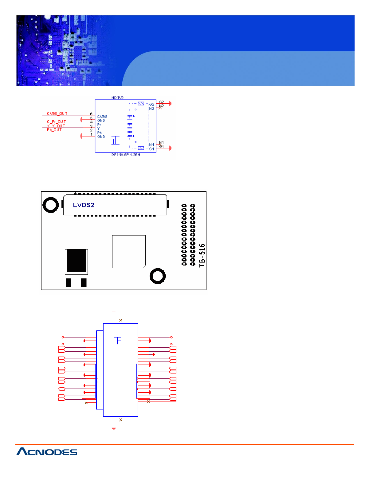
HDTV2 P ort Signal Name:
TB516 (option):
ASB-B705 SDVO1 connected C ard, Support dual channel 18/24 bit LVD S output
connector.
LVDS2 Port Signal Name:
LV DS 2_V DD 5
LVD S 2_V D D33
2LB _D0_N
2LB _D 0_P
2LB _D1_N
2LB _D 1_P
2
4
6
8
10
12
14
16
18
V C C5
G ND
V C C3
B _D 0B _D 0+
G ND
B _D 1B _D 1+
LV D S 2
V C C5
GN D
V C C3
A _D 0A _D0+
GN D
A _D 1-
A _D1+
1
3
5
7
9
11
13
15
17
LV DS 2_V D D 5
LV DS 2_V D D3 3
2LA_ D0_N
2LA_ D0_P
2LA_ D1_N
2LA_ D1_P
28 27
2LB_D 3_P
40
B _D 3+
A ple x,
10.07. 29
A _D3+
39
D F 13-40D P -1. 25V
2LA _D 3_P
LVDS2 Backlig ht control connector for INVERTER1.
Page 25
PCH 3098
8 inch Atom Fanless Panel PC
© Copyrigh t 2012 Acnodes, Inc.
All rights reserved. Product description and product specifications
are subj ect to chan ge without notice . For latest produ ct in formati on,
please visit Acnodes’ we b site at www.acnodes.c om.
14628 Central Ave.
Chin o, CA91710
Tel:909.597.7588, Fax:909. 597.1939
Signal Name
Pin#
Pin#
Signal Name
+5V 1 2
+5V
USB6_N
3 4 USB7_N
USB6_P
5 6 USB7_P
Ground
7 8 Ground
NC 9 10
Ground
22. H7 /H9: SDVO CARD SCREW HOLES, two screw holes for SDVO card assemble.
23. H 3/H4/H5 /H6: Intel Atom Z530P(or Z510P) CPU+ US15W Heat Sink SCREW HOLES, Four
screw holes for Intel CPU and US15W Heat Sink assemble.
24. LED 1/LED2 : LED STATUS. LED1:Motherboard Standb y Po wer Goo d statu s LED2 :
Motherboard CPU Pow er G ood status.
25 . U SB6 7: (2.0mm Pitch 2x5 Pin Header),Front USB connector, it provides two USB ports via a
dedicated USB cable, speed up to 480Mb/s.
U SB6 an d U SB7 can only be used for int ernal dev ice attachment as USB 2.0 SpecIfi-
cation, Can not support USB1.1 and USB 1.0 Specification.
Note:
Before connection, make sure that pin out of the USB Cable is in accordance with that of the said
tables. Any inconformity may cause system down and even hardware damages.
2 6. IDE_CF1: (CF Card socket), it is located at the bottom of the board and serves as an insert
interface for Type I and Type II Compact Flash card. The operating voltage of CF card can be set as
3.3V or 5V. The default setting of the product is 3.3V.
2 7. J TA G1: Reserve.
Page 26

PCH 3098
8 inch Atom Fanless Panel PC
© Copyrigh t 2012 Acnodes, Inc.
All ri ghts reserved . Produ ct descri pti on an d produ ct specif icati ons
are subj ect to chan ge without noti ce. For latest product informati on,
please visit Acnodes’ we b site at www.acnodes.c om.
14628 Central Ave.
Chin o, CA91710
Tel:909.597.7588, Fax:909. 597.1939
A M IB IOS© 2006 Am eri can M eg a trend s , Inc .
B IO S D ate: 02/23/11 23:27:33 Ver: 08.00.15
C PU : In
tel(R ) A to m (T M ) CPU Z 510 @ 1.10GH z
Sp eed : 600M H z
P ress F 11 for B B S PO PU P
In itializin g U SB C on trollers. . D o ne.
10 19M B O K
P ress delete to R u n SE TU P
0085
AM IB IO S© 2006 Am erican M ega tren ds , In c.
B IOS D ate: 02/23/11 23 :27:33 Ver: 08.00.15
CP U : Intel(R)
A tom (TM ) C PU Z510 @ 1.10GH z
Speed : 600 M Hz
Press F 11 for BB S P OPU P
Initializin g U SB C o ntro llers. . Do n e.
1019M B O K
Press d elete to Ru n SET UP
0085
C hapter 3 B IO S S etup
3.1 O
peration
s after PO ST Screen
A fte r CM O S d
fo l lo
win
g sc re e n fo r yo u r fu rth e r o p e ra tio n . P re ss
isch
a rg e o r BIO S fla s h in g o p e ra tio n , th e
syste
m w ill d isp la y th e
De
l e te ke y to e n te r CM O S S e tu p .
A fte r o p tim
a s fo llo ws a n d in
izin
g a n d e
xitin
g CM O S S e tu p , th e PO ST
clu
d e s b a sic in fo rm a tio n o n B IO S , CP U, m e m o ry, a n d
P re ss F 11 ke y to e n te r B o o t M e n u d u rin g P O S T, a s sh o wn b y th e fo llo win g fig u re .
scre
e n d
isp
la ye d fo r th e f irst tim e is
sto
ra g e d e
vice
s .
Page 27

PCH 3098
8 inch Atom Fanless Panel PC
© Copyrigh t 2012 Acnodes, Inc.
All rights reserved. Product description and product specifications
are subj ect to chan ge without notice . For latest produ ct in formati on,
please visit Acnodes’ we b site at www.acnodes.c om.
14628 Central Ave.
Chin o, CA91710
Tel:909.597.7588, Fax:909. 597.1939
P lease select boot device
Network: IB A G E S lot 0100 v13 53
and ? to m ove selection
E NTER to select B oot device
E SC to boot using de faults
BIOS SETUP UTILI
TY
Main
Advanc ed
PCI PnP
Boo t
S ecurity
Chips et
Exit
Syste m Ove rvie w
Us er [ENTER] [TA B]
or [SHIFT-TAB] to
S elect a field
Us e[+] or [-] to
c onfigure sy stem Time.
? Selec t Screen
?? Selec t Item
+ - Charge Field
Tab Selec t Field
F1 General Help
F10 Save an d Exit
AMIB IOS
Version : 08.00.15
B uild Date : 0 2/23/11
ID : B7 05M 003
Proc essor
Intel(R ) Atom (TM ) CPU Z5 10 @
Spe ed :600M Hz
C ount :1
System Me m ory
Siz e :1 019M B
System Time [0 0:00:18]
3.2 BIOS SETUP UTILITY
Press [Del] key to enter B IOS S etup uti lity during P OST, and then a main menu
containing sys tem summary information wil l appear.
Page 28

PCH 3098
8 inch Atom Fanless Panel PC
© Copyrigh t 2012 Acnodes, Inc.
All ri ghts reserved . Produ ct descri pti on an d produ ct specif icati ons
are subj ect to chan ge without noti ce. For latest product informati on,
please visit Acnodes’ we b site at www.acnodes.c om.
14628 Central Ave.
Chin o, CA91710
Tel:909.597.7588, Fax:909. 597.1939
Sys tem Da te [We d
C MC LO -M
odule:0 D2.023x
,
ESC Exit
v02.61 © Copyright 1985-2006 Am erican Megatrends , Inc.
BIOS SETUP
UTILITY
Main
Advanc
ed
PCI PnP
Boo t
S ecurity
Chipset
Exit
Sy stem Ove rview
Us er [ENTER] [TA B]
or [SHIFT-TAB] to
S elect a field
A MI B IOS
Ve rs ion : 08.00.15
B uild Da te : 02/23 /11
Us e[+] or [-] to
c onfigure sy stem Time.
? Selec t Screen
?? Selec t Item
+ - Charge Field
Tab Selec t Field
F1 General Help
F10 Save an d Exit
E SC E xit
ID : B
705M
003
P roc es so r
Inte l(R) A
tom(T
M) C PU Z 510 @
1 .10 GHz
S peed
:600M
H z
C oun t :1
Sy stem Me m ory
S ize
:1019M
B
S yste m Tim e
[00:02
:28]
S yste m D ate [Wed 02/23 /2011]
C M C L O-M
odule :0D2.023
x, H i-M odu le:0d2.01 6x
V 02.61 © Copyr ight 1985-2006 Amer ican Mega trends , Inc.
3.3 System Overview
S ystem Tim e:
S et the system tim e, the tim e
S ystem Date:
Set the system date, the date
Day: Note that the ‘D ay’
M onth: 01 to 12
D ate: 01 to 31
Year: 2009 to 2099
form
at is:
Hour : 0 to 23
Minute : 0 to 59
Se cond : 0 to 59
form
at is:
autom atical
ly changes w hen you set the da te.
Page 29

PCH 3098
8 inch Atom Fanless Panel PC
© Copyrigh t 2012 Acnodes, Inc.
All rights reserved. Product description and product specifications
are subj ect to chan ge without notice . For latest produ ct in formati on,
please visit Acnodes’ we b site at www.acnodes.c om.
14628 Central Ave.
Chin o, CA91710
Tel:909.597.7588, Fax:909. 597.1939
BIOS SETUP
UTILITY
Main
Advanced
PCI PnP
Boo t
S ecurity
Chipset
Exit
A dvanc ed Setting s
Configure CPU
? Se lect S creen
?? Se lect Item
E nter Charge Field
F1 General Help
F10 Save and E xit
E SC
E xit
WA RNING : Setting w rong v alues In belo w
sec ti ons
may c ause system to
malfunc
tion .
? CPU Configuration
? IDE Co nfiguration
? Su per IO
Configurati
on
? ACPI Co nfi guration
? MPS Co nfiguration
? PCI Exp re ss
Configura
tion
? Smb io s Configuration
? U SB Co nfiguration
V 02.61 © Copyr ight 1985-2006 Amer ican Mega trends , Inc.
BIOS SETUP
UTILITY
Advanced
C onfigure adv anced CPU settin gs
M odule Ver sion: 3F.0D
This should be enabled
In order to enable or
Disable th e Hardware
P refetcher Disable
Feature.
? Select Screen
?? Select Item
M anufac ture r : Intel
Intel(R) Atom(TM) C PU Z510 @ 1.10GHz
Fre quency :6 00M Hz
FSB Spe ed : 400 MHz
C ache L1 :24 KB
C ache L2 :512 KB
R atio Actual Value :6
H ardwa re Pre fe tche r [Enab led]
A djac ent Ca che Line Pre fe tch [Ena bled ]
3.4 Advanced Settings
3.4.1 CPU C onfiguration
Page 30

PCH 3098
8 inch Atom Fanless Panel PC
© Copyrigh t 2012 Acnodes, Inc.
All ri ghts reserved . Produ ct descri pti on an d produ ct specif icati ons
are subj ect to chan ge without noti ce. For latest product informati on,
please visit Acnodes’ we b site at www.acnodes.c om.
14628 Central Ave.
Chin o, CA91710
Tel:909.597.7588, Fax:909. 597.1939
Max CPUID Value Limit [Disabled]
Intel (R) Virtualizatio n Tech [Enab led]
+- Charge Field F1
Ge neral He lp F10
Save and Exit ESC
Exit
Execute -D isable Bit Capab ility [Enabled]
H yper Threading Tech nolog y
[Enabled]
Intel(R) SpeedStep (tm) t ech [Di sab led]
Intel(R) C -SATAE tech [D isabled]
V02.61 © Copyright 1985 -2006 Americ an Mega trends , Inc.
Ha rdware Prefetcher:
[Enabled]
Adjacent Cache Line Prefetch:
Max C PU ID Value Limit:
Execute-Disable B it C apability:
Hyper Threading Technology:
[Disa bled]
[Enabled]
[Disabled]
[Dis abled]
[Enabled]
[Enabled]
[Disabled]
[Enabled]
[Disabled]
Page 31

PCH 3098
8 inch Atom Fanless Panel PC
© Copyrigh t 2012 Acnodes, Inc.
All rights reserved. Product description and product specifications
are subj ect to chan ge without notice . For latest produ ct in formati on,
please visit Acnodes’ we b site at www.acnodes.c om.
14628 Central Ave.
Chin o, CA91710
Tel:909.597.7588, Fax:909. 597.1939
BIOS SETUP UTILITY
A dvanced
IDE C onfigura tion
Options
ATA/IDE Con figu ration [Compatible]
Disabled
Compatible
? Select Screen
?? Select Item
+- Charge Field F1
Ge neral He lp F10
Save and Exit ESC
Exit
? Primary IDE Master : [Not
D etected]
? Primary IDE Slaver : [Not
D etected]
H ard D isk Write Pro tect [D isabled]
IDE Detect Time Out (Sec) [35]
ATA(PI) 80P in Cab le Det ection [H ost &
D evice]
V02.61 © Copyright 1985 -2006 Americ an Mega trends , Inc.
Intel(R ) SpeedStep (tm) tech:
Intel(R ) C -SATA E tech:
3.4.2 IDE Configura tion
[Disabled]
[E
nabled
[Disabled]
[Enabled]
]
Page 32

PCH 3098
8 inch Atom Fanless Panel PC
© Copyrigh t 2012 Acnodes, Inc.
All ri ghts reserved . Produ ct descri pti on an d produ ct specif icati ons
are subj ect to chan ge without noti ce. For latest product informati on,
please visit Acnodes’ we b site at www.acnodes.c om.
14628 Central Ave.
Chin o, CA91710
Tel:909.597.7588, Fax:909. 597.1939
BIOS SETUP UTILITY
Advanced
C onfigure Win627U HG Super IO Chipset
Allow BIOS to Select
ATA/IDE Configuration:
Hard D isk Write Prote ct:
IDE Detect Time Out :
[Compatible]
[Dis abled]
[Disabled]
[Enable d]
[35]
ATA(PI) 80Pin Cable Detection:
3.4.3 Super IO Configuration
[0]
[5,10,15,20,25,30]
[Host & De vice]
[Host]
[Device ]
Page 33

PCH 3098
8 inch Atom Fanless Panel PC
© Copyrigh t 2012 Acnodes, Inc.
All rights reserved. Product description and product specifications
are subj ect to chan ge without notice . For latest produ ct in formati on,
please visit Acnodes’ we b site at www.acnodes.c om.
14628 Central Ave.
Chin o, CA91710
Tel:909.597.7588, Fax:909. 597.1939
Serial Po rt1 A ddress [3 F8 ]
Serial Port Base
Address.
Serial Po rt1 Mode [RS-23 2]
Serial Po rt2 A ddress [2 F8 ]
Serial Po rt3 A ddress [3 E8]
Serial Po rt3 IRQ [IRQ 4]
? Select Screen
?? Select Item
+- Charge Field F1
Ge neral He lp F10
Save and Exit ESC
Exit
Serial Po rt4 A ddress [2 E8]
Serial Po rt4 IRQ [IRQ 3]
V02.61 © Copyright 1985 -2006 Americ an Mega trends , Inc.
Serial Port1 Mode:
C OM1 Options: [R S232 ]
3.4.4 ACPI Configuration
ACPI Settin g:
[Advanc ed ACPI Configuration]
ACPI Version Features:
[R S485]
[R S232] for RS232 Mode
[RS485] for RS485/RS422 Mode
[ACPI V3.0]
[ACPI V2.0]
[AC PI V1.0]
Page 34

PCH 3098
8 inch Atom Fanless Panel PC
© Copyrigh t 2012 Acnodes, Inc.
All ri ghts reserved . Produ ct descri pti on an d produ ct specif icati ons
are subj ect to chan ge without noti ce. For latest product informati on,
please visit Acnodes’ we b site at www.acnodes.c om.
14628 Central Ave.
Chin o, CA91710
Tel:909.597.7588, Fax:909. 597.1939
AC PI AP IC su ppo rt:
[En ab led ]
[Chi ps et A CP I Configuration]:
AM I O EM B table:
Headle
ss m ode:
AP IC AC PI S CI IR Q:
US B D evice W akeup From S 3/s4:
[
Disable
[En ab led ]
[
Disable d]
[Disab
[E
led ]
nabled]
[Disabled]
[E nabled]
[D
isabled]
[E
nabled]
d]
Page 35

PCH 3098
8 inch Atom Fanless Panel PC
© Copyrigh t 2012 Acnodes, Inc.
All rights reserved. Product description and product specifications
are subj ect to chan ge without notice . For latest produ ct in formati on,
please visit Acnodes’ we b site at www.acnodes.c om.
14628 Central Ave.
Chin o, CA91710
Tel:909.597.7588, Fax:909. 597.1939
BIOS SETUP UTILITY
Advanced
M PS Co nfi guration
Select MPS
Revision
? Select Screen
?? Select Item
+- Charge Field F1
Ge neral He lp F10
Save and Exit ECS
Exit
MPS Revisio n [1.4 ]
V02.61 © Copyright 1985 -2006 Americ an Mega trends , Inc.
BIOS SETUP UTILITY
Advanced
PCI Express Configuration
Enables/Disables
PCI Express L0s and
L1 Link Power
States.
? Select Screen
?? Select Item
+- Charge Field
A ctive State Power -M anagement
[Disabled]
3.4.5 MPS Configuration
MPS Revis ion:
3.4.6 PC I Expres s Configuration
[1.4]
[1.1]
Page 36

PCH 3098
8 inch Atom Fanless Panel PC
© Copyrigh t 2012 Acnodes, Inc.
All ri ghts reserved . Produ ct descri pti on an d produ ct specif icati ons
are subj ect to chan ge without noti ce. For latest product informati on,
please visit Acnodes’ we b site at www.acnodes.c om.
14628 Central Ave.
Chin o, CA91710
Tel:909.597.7588, Fax:909. 597.1939
F1 General Help
F10 Save and Exit
ESC Exit
V02.61 © Copyright 1985-2006 American Mega trends , Inc.
BIOS SETUP UTILITY
Advanced
Smbios Configuration
SMBIOS SMI Wrapper
Support for PnP Func
50h-54h
? Select Screen
?? Select Item
+- Charge Field
F1 General Help
F10 Save and Exit
ESC Exit
Smb ios Smi Suppo rt [Enabled]
V02.61 © Copyright 1985 -2006 Americ an Mega trends , Inc.
Active State Pow er Man agem ent:
3.4.7 Smbios Con figura tion
[Disabled]
[Enabled]
Smbios Smi Supp ort:
[Enabled]
[Disabled]
Page 37

© Copyrigh t 2012 Acnodes, Inc.
All rights reserved. Product description and product specifications
are subj ect to chan ge without notice . For latest produ ct in formati on,
please visit Acnodes’ we b site at www.acnodes.c om.
14628 Central Ave.
Chin o, CA91710
Tel:909.597.7588, Fax:909. 597.1939
PCH 3098
8 inch Atom Fanless Panel PC
BIOS SETUP UTILITY
Advanced
U SB Config uration
Enables support for
legacy USB.AUTO
Modu le Version – 2.24 .3-1 3.4
U SB Dev ices En abled :
1Keyboard
Leg acy US B Support [Enab led]
U SB2.0 Co ntroller Mod e
[H iSpeed]
BIO S EH CI Han d-Off [Enab led]
option disab les legacy
support if no USB
devices are connected
? Select Screen
?? Select Item
+- Charge Field
F1 General Help
F10 Save and Exit
ESC Exit
V02.61 © Copyright 1985-2006 America n Mega trends , Inc.
3.4.8 USB Configuration
Legac y U SB Support:
[Enabled]
[D isabled]
USB2.0 C ontroller Mode:
BIOS EHCI H and-Off:
[HiSpeed]
[Enabled ]
[Disab led]
[FullSpeed]
Page 38

© Copyrigh t 2012 Acnodes, Inc.
All ri ghts reserved . Produ ct descri pti on an d produ ct specif icati ons
are subj ect to chan ge without noti ce. For latest product informati on,
please visit Acnodes’ we b site at www.acnodes.c om.
14628 Central Ave.
Chin o, CA91710
Tel:909.597.7588, Fax:909. 597.1939
PCH 3098
8 inch Atom Fanless Panel PC
B I O S S E T U P U T I L I T Y
M a in A d v a n c e d
P C I P N P
B o o t
S e c u ri t y
C h ip s et E x it
A d v a n c e d P C I / P n P S e tt i n g s
C le a r N U R A M d u ri n g
S y s t e m B o o t .
W A R N I N G : S e t ti n g w r o n g v a l u e s I n b e l o w
s e c t i o n s
m a y c a u s e s y s te m t o m a l f u n c t i o n .
C lea r NV RA M [N o]
?
Selec
t Screen
??
Selec
t Item
+- Charge Field F1
Ge neral He lp F10
Sav e and Exit ESC
Ex it
Plu g & Pla y O/S [No ]
PC I L ate nc y Time r [64]
A lloca te IR Q to P CI V GA [Ye s]
Pa lette Snoo ping [Dis abled ]
PC I IDE Bus M as ter [Dis ab led]
O ffBo ard PCI/ISA IDE Ca rd [A uto]
IR Q3
[Av ailable ]
IR Q4
[Av ailable ]
IR Q5
[Av ailable ]
IR Q7
[Av ailable ]
IR Q9
[Av ailable ]
IR Q10
[Av ailable ]
IR Q11
[Av ailable ]
V02.61 © Copyright 1985 -2006 Am eric an Mega trends , Inc.
3 . 5 A d v a n c e d P C I / P n P S e t t i n g s
T h i s p a rt d e s c ri b e s c o n f ig u r a t io n s t o b e m a d e o n P C I b u s s y s t e m . P C I , n a m e l y
P e r s o n a l C o m p u t e r I n t e r c o n n e c t , is a c o m p u t e r b u s t h a t a llo w s I / O d e v ic e t o o p e ra t e
n e a rly a s f a s t a s C P U in i t s o w n w a y . S o m e t e c h n i c a l t e r m s w ill b e m e n t i o n e d h e re . W e
r e c o m m e n d t h a t n o n -p r o fe s s i o n a l u s e r s n o t m a k e c h a n g e s f r o m f a c t o r y d e fa u l t
s e t t i n g s .
Page 39

© Copyrigh t 2012 Acnodes, Inc.
All rights reserved. Product description and product specifications
are subj ect to chan ge without notice . For latest produ ct in formati on,
please visit Acnodes’ we b site at www.acnodes.c om.
14628 Central Ave.
Chin o, CA91710
Tel:909.597.7588, Fax:909. 597.1939
PCH 3098
8 inch Atom Fanless Panel PC
Clear NVRAM:
[No]
[Yes ]
Plug & Play OS:
[No]
[Yes ]
PC I Latency Timer:
[64]
[32]
[96]
[128]
[160]
[192]
[224]
Allocate IRQ to PCI VGA:
[248]
[Yes]
[
No]
Pa lette Snooping:
PC I IDE BusMaster:
[Disabled]
[Ena bled ]
[Disable d]
[Ena bled ]
Page 40

© Copyrigh t 2012 Acnodes, Inc.
All ri ghts reserved . Produ ct descri pti on an d produ ct specif icati ons
are subj ect to chan ge without noti ce. For latest product informati on,
please visit Acnodes’ we b site at www.acnodes.c om.
14628 Central Ave.
Chin o, CA91710
Tel:909.597.7588, Fax:909. 597.1939
PCH 3098
8 inch Atom Fanless Panel PC
OffB oard PC I/ISA IDE Card:
Some PCI ID E ca rds ma y require this to be set to the PCI slot number that is
hold ing the card. Auto:Works for most PCI IDE Cards.
[Auto]
[PC I Slo t1]
[PC I Slo t2]
[PC I Slo t3]
[PC I Slo t4]
[PC I Slo t5]
[PC I Slo t6]
IR Q3/4/5/7/9/10/11/14/15:
Available: Specif ied IRQ is available to be us ed by PC I/PnP devices .
Reserved: Specified IR Q is reserved fo r us e b y legacy ISA devices.
D MA C hannel 0/1/3 /5/6/7:
Ava ilable: Specified D MA is available to be used by PCI/PnP devic es.
[Available]
[
Reserved]
[Available]
[
Reserved]
Reserved: Specified D MA is res erv ed f or u se by legacy ISA de vices.
R eserved Memory Size:
Size of memory block t o reserv e for legacy ISA devices.
[Disabled]
[16k]
[32k]
[64k]
Page 41

© Copyrigh t 2012 Acnodes, Inc.
All rights reserved. Product description and product specifications
are subj ect to chan ge without notice . For latest produ ct in formati on,
please visit Acnodes’ we b site at www.acnodes.c om.
14628 Central Ave.
Chin o, CA91710
Tel:909.597.7588, Fax:909. 597.1939
PCH 3098
8 inch Atom Fanless Panel PC
BIOS SETUP UTILITY
Main
Advance d
PCIPnP
Boot
Security
Chipset
Exit
Boot Setting s
Configure Settings
During System Boot
? Select Screen
?? Select Item
Enter Go to sub screen
F1 General Help
F10 Save and Exit
ESC Exit
? Boot Settin g Configuration
? Boot Device Priority
? Hard D isk Drives
V02.61 © Copyright 1985-2006 America n Mega trends , Inc.
3.6 Boot Settings
Boot Setting C onfiguration
Conf igure Settings during System Boot.
Quick Boot:
Allow s BIOS to skip certain tests w hile bootin g .This will decrease the time
needed to boot the s ystem.
[Enabled]
[Disab led]
Page 42

© Copyrigh t 2012 Acnodes, Inc.
All ri ghts reserved . Produ ct descri pti on an d produ ct specif icati ons
are subj ect to chan ge without noti ce. For latest product informati on,
please visit Acnodes’ we b site at www.acnodes.c om.
14628 Central Ave.
Chin o, CA91710
Tel:909.597.7588, Fax:909. 597.1939
PCH 3098
8 inch Atom Fanless Panel PC
Quiet Boot:
[Disabled]
[Enabled]
Disabled: D isplays n ormal POST messages.
Enabled: Displays O EM logo in stead of POST mess ages.
AddOn RO M Displa y Mode:
Set display mode for Option RO M.
[Force B IOS]
[Keep Current]
Bootup Num-Lock :
Select Power-on state for Numlock .
[O n]
[O ff]
Wait For ‘F1’ If Error:
Wait for F1 key to be pressed if error occurs.
[Enabled]
[Disabled]
Hit ‘D EL’Mes sgae Dis play :
D isplays “press ” DEL to ru n Setup in POST.
[Enabled]
Interrupt 19 C apture:
Enabled: Allow s option RO Ms to trap interrupt 19.
[Disabled]
[Disabled]
[Enable d]
Page 43

© Copyrigh t 2012 Acnodes, Inc.
All rights reserved. Product description and product specifications
are subj ect to chan ge without notice . For latest produ ct in formati on,
please visit Acnodes’ we b site at www.acnodes.c om.
14628 Central Ave.
Chin o, CA91710
Tel:909.597.7588, Fax:909. 597.1939
PCH 3098
8 inch Atom Fanless Panel PC
BIOS S ETUP UTILITY
Main
A dvanced
PCIPnP
Boot
Security
Chipset
Exit
Security Settings
Install or Change the
password.
Supervisor Password :Not Insta lled
User Passw ord :N ot Installed
Chan ge S upervisor P assw ord
Chan ge User Passwo rd
? Select Screen
?? Select Item
Enter Charg e
F1 General Help
F10 Save and Exit
ESC Exit
Boot Sect or Virus Protection [Disabled]
V02.61 © Copyright 1985 -2006 Americ an Mega trends , Inc.
Boot D evice Priority:
Specifies the Boo t Device Priority sequen ce.
Hard D isk Devices :
Specifie s the Boot D evice Priority sequence f rom av ailable H ard D rives.
3.7 Security Settings
C hange Supervis or Passw ord:
I nstall or Change the password.
Change U ser Pas sword:
I nstall or Change the password.
Page 44

© Copyrigh t 2012 Acnodes, Inc.
All ri ghts reserved . Produ ct descri pti on an d produ ct specif icati ons
are subj ect to chan ge without noti ce. For latest product informati on,
please visit Acnodes’ we b site at www.acnodes.c om.
14628 Central Ave.
Chin o, CA91710
Tel:909.597.7588, Fax:909. 597.1939
PCH 3098
8 inch Atom Fanless Panel PC
Boot Sector Virus Prote ction:
[Disabled]
[Enabled]
Enabled / D isabled Boot Sec tor Virus Protection.
Type the passw ord with up to 6 ch arac te rs and then pres s Enter key.
This will clear a ll previously typed C MO S pass words. You will be requested to
confirm the passw ord . Ty pe the pas sword again and press En ter key. You
may press
To cle ar the pass word, just press
input window pops up. A co nf irma tion message will be shown on the screen as to
whether the passw ord will be disabled. You will ha ve direct acc ess to BIOS setup
without typing any pass word after system reboot once the passwo rd is disabled .
Once the pass word feature is used, you w ill be reques ted to t ype the pas sword
eac h t ime you enter BIOS setup. This will prevent unauthorized persons from
ch anging your system c onf igurations.
Also, the feature is capable of requesting us ers to enter the password prior to
sy stem boot to control unauthorized acc ess to your computer. Us ers may enable the
feature in Security O ption of Advanced BIOS Features. If Security O ption is set to
Esc ke y to abandon pas sword entry operation.
Enter
k ey when passw ord
System, you will be reques ted to enter the pass word before system boot and when
entering BIOS setup; if Sec urity Option is set to Setup, you will be requested for
passw ord for enterin g BIOS setup.
Page 45

© Copyrigh t 2012 Acnodes, Inc.
All rights reserved. Product description and product specifications
are subj ect to chan ge without notice . For latest produ ct in formati on,
please visit Acnodes’ we b site at www.acnodes.c om.
14628 Central Ave.
Chin o, CA91710
Tel:909.597.7588, Fax:909. 597.1939
PCH 3098
8 inch Atom Fanless Panel PC
BIOS SETUP UTILITY
Main
Advanced
PCIPnP
B oot
Security
Chipset
Exit
Advanc ed Chipset Se ttin gs
Configure North Bridge
f eature
? Select Screen
?? Select Item
E nter Go to sub screen
F1 Gen eral Help
F10 Save and Exit
E SC Exit
WA RNIN G: Setting wro ng v alues in belo w
se ctions
ma y cause system to malfunc tion
? N orth Bridge C onfigurat ion
? South B rid ge Con figu ration
V 02.61 © Copyright 1985-20 06 Amer ican Mega trends , Inc.
BIOS SETUP UTILITY
Chipset
N orth B rid ge Chipset C onfigura tio n
Se lect which graphics
Controller to use as
The primary boot
device
? S elect Screen
?? S elect Item
+- Charge Field
F1 General Help
F10 Save and Exit
ES C E xit
Primar y Gr aphics A dapter
[PCIe/IGD]
Integra te d Gr aph ics M ode S elec
[E nabled ,4MB ]
? B oot Display C onfiguration
3.8 Advanced Chipset Settings
Note: D ue to limited address l ength of BIO S, only a portion of panel parameters are list ed in
BIO S Setup. If the connected panel i s not included i n the parameter list, display
pro blem will occur. In this case, Please do not change BIOS setup.
3.8.1 North Bridge Configura tion
Page 46

© Copyrigh t 2012 Acnodes, Inc.
All ri ghts reserved . Produ ct descri pti on an d produ ct specif icati ons
are subj ect to chan ge without noti ce. For latest product informati on,
please visit Acnodes’ we b site at www.acnodes.c om.
14628 Central Ave.
Chin o, CA91710
Tel:909.597.7588, Fax:909. 597.1939
PCH 3098
8 inch Atom Fanless Panel PC
B IOS
SETU
P U T
ILIT Y
C
hips
et
B oot D is p lay C on f igu r atio n
Opti ons
Auto
Integrated
LVD
S
Ex ternal DV
I/HD
M I
Ex ternal TV
Ex ternal C RT
Ex ternal
LVD
S
?
Sel
ec t Screen
??
Sel
ec t Item
+- C harge
opti
on
F 1
Gener
al H elp
F 10 Save and E xit
ES C Ex it
B oot D is play D e vice [ A uto]
L oc al Fla t P a nel S ca ling [A uto]
F la t P a nel Type [ 102 4x768
18 bit ]
P ane l B ri
ghtnes
s C ontrol [ L eve l 9 ]
D P S T C ontrol
[ V BI O S - D e fa ult]
T V S tanda rd
[ V BI O S - D e fa ult]
V02.61 © C o p
yrig
h t 1985 -2006 Am eric an M eg a
trend
s , Inc.
V02.61 © C o
pyrig
ht 1985-2006 Am erican M eg a
tren
d s ,
Inc.
P r ima ry G r a ph ic s A d a p te r:
[P C Ie /IG D ]
[IG D ]
Inte g r a te d G ra p h ic s M od e S e le c :
[ E n ab led , 4M B ]
[E na bled ,1 M B ]
[E na bled ,8 M B ]
[D is ab
led]
B o o t D is p la y C o nfig u ra tio n :
Page 47

© Copyrigh t 2012 Acnodes, Inc.
All rights reserved. Product description and product specifications
are subj ect to chan ge without notice . For latest produ ct in formati on,
please visit Acnodes’ we b site at www.acnodes.c om.
14628 Central Ave.
Chin o, CA91710
Tel:909.597.7588, Fax:909. 597.1939
PCH 3098
8 inch Atom Fanless Panel PC
Boot Display Device:
[Auto]
[Integrated LVDS]
[External DVI/
[External TV]
Flat P anel Type:
B ackl ight Co ntro l Suppor t
P anel Backlight Control:
HDMI
]
[External CRT]
[External LVDS]
[10 24x 76 8 1 8bit ]
[640x480 18bit ]
[800x600 18bi t ]
[1280x768 18bit ]
[1280x800 18bit ]
[10 24 x 768 24bit ]
[VB IO S-D efault]
[Bo th B LC & BIA Di sab led]
[B LC E nabled]
[Level9]
[Level 0]
[Level 1]
[Level 2]
[Level 3]
[Level 4]
[Level 6]
[Level 7]
[Level 8]
[Level 9]
[Level 10]
[Level 11]
[Level 12]
[Level 13]
[Level 14]
[Level 15]
[Level 16]
Page 48

© Copyrigh t 2012 Acnodes, Inc.
All ri ghts reserved . Produ ct descri pti on an d produ ct specif icati ons
are subj ect to chan ge without noti ce. For latest product informati on,
please visit Acnodes’ we b site at www.acnodes.c om.
14628 Central Ave.
Chin o, CA91710
Tel:909.597.7588, Fax:909. 597.1939
PCH 3098
8 inch Atom Fanless Panel PC
Note : Panel s upport PWM Func tion.
D PST C ontrol:
[V BIOS-Defa ult]
[D PST Disab led]
[D PST Enabled at L evel]
[D PST Enabled at L eve2]
[D PST Enabled at L eve3
[D PST Enabled at L eve4]
[D PST Enabled at L eve5]
TV Standard :
[V BIOS-Default]
[N TSC ]
[PAL]
[SECAM]
[SMPTE240M]
[ITU -R television]
[SMPTE296M]
[C EA 7702]
[C EA 7703]
Page 49

© Copyrigh t 2012 Acnodes, Inc.
All rights reserved. Product description and product specifications
are subj ect to chan ge without notice . For latest produ ct in formati on,
please visit Acnodes’ we b site at www.acnodes.c om.
14628 Central Ave.
Chin o, CA91710
Tel:909.597.7588, Fax:909. 597.1939
PCH 3098
8 inch Atom Fanless Panel PC
BIOS SETUP UTILITY
Chipset
Sou th Bridge Chipset Configuration
Number of UCHI
Ports in system
ECHI ONLY is
Automatically
Assed.
? Select Screen
?? Select Item
+- Charge Field F1
Ge neral He lp F10
Save and Exit ESC
Exit
U SB Functio ns [8 USB
Po rts]
U SB2.0 Co ntroller [Enab led]
U SB Client Con tro ller [Disab led]
SDIO Con tro ller [En abled]
A udio Co ntroller Cod ec [A uto]
Reserved Page Ro ute [LPC]
Serial IRQ Mo de [Quiet]
PCIE Ports Configuratio n
PCIE Port 0 [Auto]
PCIE Port 1 [Au to]
V02.61 © Copyright 1985 -2006 Americ an Mega trends , Inc.
3.8.2 South B ridge Configuration:
USB Functions:
[8 USB Ports]
[D isabled]
[2 U SB Po rts]
[4 U SB Po rts]
[6 U SB Po rts]
USB 2.0 C ontroller:
[Enabled]
[D isabled]
Page 50

© Copyrigh t 2012 Acnodes, Inc.
All ri ghts reserved . Produ ct descri pti on an d produ ct specif icati ons
are subj ect to chan ge without noti ce. For latest product informati on,
please visit Acnodes’ we b site at www.acnodes.c om.
14628 Central Ave.
Chin o, CA91710
Tel:909.597.7588, Fax:909. 597.1939
PCH 3098
8 inch Atom Fanless Panel PC
U SB Client C ontroller:
[Disabled]
[Enabled]
SD IO Con tro ller:
[Enabled]
[Disab led]
Audio Controller Codec:
Re served Pa ge R oute:
PCIE Ports C onfigu ration:
PC IE Port 0:
PC IE Port 1:
[ Auto]
[Azalia]
[D isabled]
[LPC]
[PCI]
[Auto]
[Enabled ]
[Disabled]
[A uto]
[Enabled ]
[Disabled]
[Enabled ]
[Disabled]
Page 51

© Copyrigh t 2012 Acnodes, Inc.
All rights reserved. Product description and product specifications
are subj ect to chan ge without notice . For latest produ ct in formati on,
please visit Acnodes’ we b site at www.acnodes.c om.
14628 Central Ave.
Chin o, CA91710
Tel:909.597.7588, Fax:909. 597.1939
PCH 3098
8 inch Atom Fanless Panel PC
BIOS SETUP UTILITY
Main
Advanced
PCI PnP
Boo t
Security
Chipset
Exit
Exit Options
Exit syste m setup
after saving the
changes
F10 key can be used
For this operation
? Select Screen
?? Select Item
Enter Go to sub screen
F1 General Help
F10 Save an d Exit
ESC Exit
S ave Chang es an d Exit
Discard Chang es an d Exi t
D iscard Changes
Load Optimal D efaults
Load Failsa fe D efau lts
V02.61 © Copyr ight 1985-2006 Amer ican Mega trends , Inc.
3.9 Exit Options
Sa ve C ha nges and Ex it:
Save c onfiguration changes and exit setup?
(F10 key can be used for this operation)
[OK]
[Can cel]
Page 52

© Copyrigh t 2012 Acnodes, Inc.
All ri ghts reserved . Produ ct descri pti on an d produ ct specif icati ons
are subj ect to chan ge without noti ce. For latest product informati on,
please visit Acnodes’ we b site at www.acnodes.c om.
14628 Central Ave.
Chin o, CA91710
Tel:909.597.7588, Fax:909. 597.1939
PCH 3098
8 inch Atom Fanless Panel PC
Discard C hanges and Exit:
D iscard Chan ges and Exit setup?
(ESC key can be used for this operation )
D iscard C hanges:
[O K]
[C ancel]
Dis card changes?
(F7 key can be used f or this operation)
Load O ptimized Defaults:
Load FailSafe Defaults:
Load O ptimized D efaults?
(F9 key can be use d for this operation)
Load FailSafe D ef aults?
(F9 key can be use d for this operation)
[O K]
[C ancel]
[OK]
[Cancel]
[OK]
[Cancel]
Page 53

© Copyrigh t 2012 Acnodes, Inc.
All rights reserved. Product description and product specifications
are subj ect to chan ge without notice . For latest produ ct in formati on,
please visit Acnodes’ we b site at www.acnodes.c om.
14628 Central Ave.
Chin o, CA91710
Tel:909.597.7588, Fax:909. 597.1939
PCH 3098
8 inch Atom Fanless Panel PC
Chapter 4 Installation of Drivers
Thi s chapter de scribes the installation procedures for software and drivers under the windows X P. The
s oftware and drivers are included w ith the motherboa rd. The contents incl ude Intel chipset driver
V GA dri ver LAN dri vers Audio dri ver
Installation instructions are given below.
Im portant Note:
A fter i nstalling you r W indows operat ing system (W indows X P), you mu st ins tall
first the Intel Chipset Softw are In stal lation Uti lity before proceeding with the
instal lation of drivers.
I
Page 54

© Copyrigh t 2012 Acnodes, Inc.
All ri ghts reserved . Produ ct descri pti on an d produ ct specif icati ons
are subj ect to chan ge without noti ce. For latest product informati on,
please visit Acnodes’ we b site at www.acnodes.c om.
14628 Central Ave.
Chin o, CA91710
Tel:909.597.7588, Fax:909. 597.1939
PCH 3098
8 inch Atom Fanless Panel PC
4.1 Intel Chipset Driver
To i nstall the Intel chipset driver, please fo llow the steps below.
S tep 1: S elect C hipset from the list
Foll ow the step-by-step in stallation proces s to install the LMS_S QL driver.
Page 55

© Copyrigh t 2012 Acnodes, Inc.
All rights reserved. Product description and product specifications
are subj ect to chan ge without notice . For latest produ ct in formati on,
please visit Acnodes’ we b site at www.acnodes.c om.
14628 Central Ave.
Chin o, CA91710
Tel:909.597.7588, Fax:909. 597.1939
PCH 3098
8 inch Atom Fanless Panel PC
Page 56

© Copyrigh t 2012 Acnodes, Inc.
All ri ghts reserved . Produ ct descri pti on an d produ ct specif icati ons
are subj ect to chan ge without noti ce. For latest product informati on,
please visit Acnodes’ we b site at www.acnodes.c om.
14628 Central Ave.
Chin o, CA91710
Tel:909.597.7588, Fax:909. 597.1939
PCH 3098
8 inch Atom Fanless Panel PC
C lick Fin ish, W hen the
p icture.
installati
on process is c om plete, the S etup
Com
plete s cre en app ears. S ee as
Page 57

© Copyrigh t 2012 Acnodes, Inc.
All rights reserved. Product description and product specifications
are subj ect to chan ge without notice . For latest produ ct in formati on,
please visit Acnodes’ we b site at www.acnodes.c om.
14628 Central Ave.
Chin o, CA91710
Tel:909.597.7588, Fax:909. 597.1939
PCH 3098
8 inch Atom Fanless Panel PC
4.2 Intel Graphics Media Accelerator Driver
To install the VGA drivers, follow the steps below to proceed with the installation.
1. Click Intel(R) US15W Chipset Family Graphics Driver.
Follow the step-by-step installation process to install the Graphics Media Accelerator driver.
Page 58

PCH 3098
8 inch Atom Fanless Panel PC
© Copyrigh t 2012 Acnodes, Inc.
All ri ghts reserved . Produ ct descri pti on an d produ ct specif icati ons
are subj ect to chan ge without noti ce. For latest product informati on,
please visit Acnodes’ we b site at www.acnodes.c om.
14628 Central Ave.
Chin o, CA91710
Tel:909.597.7588, Fax:909. 597.1939
Page 59

PCH 3098
8 inch Atom Fanless Panel PC
© Copyrigh t 2012 Acnodes, Inc.
All rights reserved. Product description and product specifications
are subj ect to chan ge without notice . For latest produ ct in formati on,
please visit Acnodes’ we b site at www.acnodes.c om.
14628 Central Ave.
Chin o, CA91710
Tel:909.597.7588, Fax:909. 597.1939
C lick FIN ISH ; A Driver Ins tal lation
Com
pl et e.
Page 60

PCH 3098
8 inch Atom Fanless Panel PC
© Copyrigh t 2012 Acnodes, Inc.
All ri ghts reserved . Produ ct descri pti on an d produ ct specif icati ons
are subj ect to chan ge without noti ce. For latest product informati on,
please visit Acnodes’ we b site at www.acnodes.c om.
14628 Central Ave.
Chin o, CA91710
Tel:909.597.7588, Fax:909. 597.1939
4.3 In tel 8257L Gb e LAN Device D ri ver
To in sta ll th e In te l R 8 2 5 7 L G b e G ig a b it L A N c o n n e ct d e vice d rive r, p l e a se fo llo w th e ste p s b e lo w.
S e le c t L AN fro m th e l ist
F o ll o w th e ste p -b
y-ste
p in sta lla tio n p ro ce s s to in sta ll th e L AN d rive r.
Page 61

PCH 3098
8 inch Atom Fanless Panel PC
© Copyrigh t 2012 Acnodes, Inc.
All rights reserved. Product description and product specifications
are subj ect to chan ge without notice . For latest produ ct in formati on,
please visit Acnodes’ we b site at www.acnodes.c om.
14628 Central Ave.
Chin o, CA91710
Tel:909.597.7588, Fax:909. 597.1939
Page 62

PCH 3098
8 inch Atom Fanless Panel PC
© Copyrigh t 2012 Acnodes, Inc.
All ri ghts reserved . Produ ct descri pti on an d produ ct specif icati ons
are subj ect to chan ge without noti ce. For latest product informati on,
please visit Acnodes’ we b site at www.acnodes.c om.
14628 Central Ave.
Chin o, CA91710
Tel:909.597.7588, Fax:909. 597.1939
C lick FIN ISH ; A Driver Ins tal lation Compl et e.
Page 63

PCH 3098
8 inch Atom Fanless Panel PC
© Copyrigh t 2012 Acnodes, Inc.
All rights reserved. Product description and product specifications
are subj ect to chan ge without notice . For latest produ ct in formati on,
please visit Acnodes’ we b site at www.acnodes.c om.
14628 Central Ave.
Chin o, CA91710
Tel:909.597.7588, Fax:909. 597.1939
4.4 Realtek HD Audio Driver Installation
To i nstall the R ealtek High D efiniti on (H D) A udio driver, please follo w the steps below .
S elec t Audi o from the list
Foll ow the step-by-step ins tallation process to install the Realtek H D A udio driver .
Page 64

PCH 3098
8 inch Atom Fanless Panel PC
© Copyrigh t 2012 Acnodes, Inc.
All ri ghts reserved . Produ ct descri pti on an d produ ct specif icati ons
are subj ect to chan ge without noti ce. For latest product informati on,
please visit Acnodes’ we b site at www.acnodes.c om.
14628 Central Ave.
Chino, CA91710
Tel:909.597.7588, Fax:909. 597.1939
C lick FIN ISH ; A Driver Installation Complete.
Page 65

PCH 3098
8 inch Atom Fanless Panel PC
© Copyrigh t 2012 Acnodes, Inc.
All rights reserved. Product description and product specifications
are subj ect to chan ge without notice . For latest produ ct in formati on,
please visit Acnodes’ we b site at www.acnodes.c om.
14628 Central Ave.
Chin o, CA91710
Tel:909.597.7588, Fax:909. 597.1939
Chapter 5 Tou ch Screen Installation
This chapter describes ho w to install drivers and other software that will allow you r PenMount 6000
C ontroller Board to w ork with different operating systems .
N OTE: PenMount U SB drivers suppo rt up to 15 U SB controllers.
5.1 Introduction to Touch Screen Controller Board
PenMount 6300 U SB control board is a tou ch screen control board designed for USB interface and
s pecific f or 4, 5, 8-wire touch screens. It is des igned with U SB interface features with multiple devi ces
s upporting function. PenMount 6300 control board using PenMount 6000 controller that has been
d esigned for those who may like and all-in-one so lution with 10-bit A/D co nverter built-in to ma ke the
to tal printed circuit board denser, circ uit diagram also des igned for 12-bit ADC for optional. There are
tw o connectors on this board , one c onnector is for 4, 5, 8-w ire touch screen cable (o ptional), and
a nother is for 4-pin USB A type cable (optiona l).
Figure 5.1: Bird’s Eye View of Control Board
Page 66

PCH 3098
8 inch Atom Fanless Panel PC
© Copyrigh t 2012 Acnodes, Inc.
All ri ghts reserved . Produ ct descri pti on an d produ ct specif icati ons
are subj ect to chan ge without noti ce. For latest product informati on,
please visit Acnodes’ we b site at www.acnodes.c om.
14628 Central Ave.
Chino, CA91710
Tel:909.597.7588, Fax:909. 597.1939
5.2 W indows
2000/XP
/2003/Vista U niversal Driver
Installatio
fo r
PenMo
B efore
i nstalled and running on y our c om puter. You m ust als o ha ve one of the follow ing Pe nMo unt 6000
s eri es controller or control boards ins talled: PM 65 00 , PM 6300.
instal
ling the W indows 2000 /XP dri ver software, you m ust have the W indows 2000/XP system
unt 6000 Series
5.2.1 In stalling S oftware
If you have an older version of the P enM ount W indows
rem ove it first. F ollow the steps below t o install the P enM ount DM C 600 0 W indow s
1 . P leas e m ake sure y our P enM ount 6000 device had plugged in advance. If your
i nterf ace, please plugged in b efo re the m ac hine is turned on. W hen the sys tem fi rst dete cts the
c ontroller board , a screen appears that shows “U nknown D evice”. D o not use this
P ress C ancel.
2000/X
P driver
instal
led i n yo ur syst em , please
2000
/X P driver.
devi
ce uses R S232
hardw
are wizard.
n
2 . Insert the Aplex produc t CD install setup.exe. t he screen below would appear. Click touch panel
d rive r
Page 67

PCH 3098
8 inch Atom Fanless Panel PC
© Copyrigh t 2012 Acnodes, Inc.
All rights reserved. Product description and product specifications
are subj ect to chan ge without notice . For latest produ ct in formati on,
please visit Acnodes’ we b site at www.acnodes.c om.
14628 Central Ave.
Chin o, CA91710
Tel:909.597.7588, Fax:909. 597.1939
3 . A L ic e n se A
4 .
Re
a d y to In
gre
e m e n t a p p e a rs. C lick “I Ag r e e … ” a n d “Ne
sta
ll th e
Pro
g ra m . Clic k “I ns ta ll”
x t”
Page 68

PCH 3098
8 inch Atom Fanless Panel PC
© Copyrigh t 2012 Acnodes, Inc.
All ri ghts reserved . Produ ct descri pti on an d produ ct specif icati ons
are subj ect to chan ge without noti ce. For latest product informati on,
please visit Acnodes’ we b site at www.acnodes.c om.
14628 Central Ave.
Chin o, CA91710
Tel:909.597.7588, Fax:909.597.1939
5 . Installing
Page 69

PCH 3098
8 inch Atom Fanless Panel PC
© Copyrigh t 2012 Acnodes, Inc.
All rights reserved. Product description and product specifications
are subj ect to chan ge without notice . For latest produ ct in formati on,
please visit Acnodes’ we b site at www.acnodes.c om.
14628 Central Ave.
Chin o, CA91710
Tel:909.597.7588, Fax:909. 597.1939
6 . The “Install Shie ld W i zard C om pleted”
appears
. Clic k “Finish”.
Page 70

PCH 3098
8 inch Atom Fanless Panel PC
© Copyrigh t 2012 Acnodes, Inc.
All ri ghts reserved . Produ ct descri pti on an d produ ct specif icati ons
are subj ect to chan ge without noti ce. For latest product informati on,
please visit Acnodes’ we b site at www.acnodes.c om.
14628 Central Ave.
Chin o, CA91710
Tel:909.597.7588, Fax:909.597.1939
5.2.2 Software Functions
Upon re boo ting, the computer automatically f inds the new 6000 co ntroller board. The touch screen is
connected but not calibrated. Follow th e procedures below to carry out ca libration.
1. After installa tion, click the PenMount Monito r icon “PM” in the menu bar.
2. When the PenMount Control Panel appears, select a device to “Calibrate.”
PenMount Control Panel
The functio ns of the PenMount Control Panel are Device, Multiple Monitors ,Tools and About,
which are explained in the following sections.
Device
In this window, you can find out that how many devices be detected on yo ur system.
Calibrate
This fun ction offers two ways to calibrate your touch screen. ‘Standard Calibration’ adjusts most touch
screens. ‘Advanced Calibration’ adjusts aging touch screens.
Standard Calib ration Click this button and arrows appea r
pointi ng to red squares. Use your finger or
stylus to touch the red squares in
sequence. After the fifth red point
cal ibration is complete. To skip, press
‘ESC’.
Page 71

PCH 3098
8 inch Atom Fanless Panel PC
© Copyrigh t 2012 Acnodes, Inc.
All rights reserved. Product description and product specifications
are subj ect to chan ge without notice . For latest produ ct in formati on,
please visit Acnodes’ we b site at www.acnodes.c om.
14628 Central Ave.
Chin o, CA91710
Tel:909.597.7588, Fax:909. 597.1939
Advanc ed Calibration
Advanced C alibration uses 4, 9, 16 or 25
points to eff ectively c alibrate touch panel
linearity of aged touch screens. Click this
button and touch the red squares in
sequence w ith a styl us. To skip, pres s
ESC’.
Command Calibration
Command call calibra tion function. Use
command mode call calibration function,
this can uses Standard, 4, 9, 16 or 25
points to calibrate E.g. Please run ms-dos
prompt or c ommand prom pt c :\Program
Files\PenMount Univers a Driver\Dmcc trl.exe
-c alibration 0 ( Standard C alibration)
Dmcc trl.e xe - c alibration ($) 0= Standard
Calib ratio n 4=Advanced Calibration 4
9=Advanced C alibration 9 16=Advanced
Calib ratio n 16 25=Advanced C alibration 25
Page 72

PCH 3098
8 inch Atom Fanless Panel PC
© Copyrigh t 2012 Acnodes, Inc.
All ri ghts reserved . Produ ct descri pti on an d produ ct specif icati ons
are subj ect to chan ge without noti ce. For latest product informati on,
please visit Acnodes’ we b site at www.acnodes.c om.
14628 Central Ave.
Chin o, CA91710
Tel:909.597.7588, Fax:909.597.1939
1 . Pl ea se se le ct a d e vi ce th e n clic k “C o n fig u re ”. Yo u ca n a lso d o u b le cli ck th e d e vic e to o .
2 .C lic k
“Sta
n d a rd C a lib ra tio n ” to
sta
rt ca li b ra tio n p ro ce d u re
Page 73

PCH 3098
8 inch Atom Fanless Panel PC
© Copyrigh t 2012 Acnodes, Inc.
All rights reserved. Product description and product specifications
are subj ect to chan ge without notice . For latest produ ct in formati on,
please visit Acnodes’ we b site at www.acnodes.c om.
14628 Central Ave.
Chin o, CA91710
Tel:909.597.7588, Fax:909. 597.1939
N O T E: T h e o ld e r th e to u ch s cre e n , th e m o re A d va n ce d M o d e ca l ib ra ti o n p o in ts yo u n ee d f o r a n
a ccu ra te ca lib ra tio n . U se a stylu s d u rin g Ad v a n ce d C a li b ra ti o n fo r g re a te r a ccu ra cy. Ple a se f o llo w th e
s te p a s b e lo w :
3 .C o m e b a ck to “Pe n M o u n t C o n tro l Pa n e l” a n d se l e ct “T o o ls” th e n C lick “A d v a nc e d
C a lib ra tio n ”.
Selec t “Device” to calibrate, then you can s tart to do “Advanced Calibration”.
Page 74

PCH 3098
8 inch Atom Fanless Panel PC
© Copyrigh t 2012 Acnodes, Inc.
All ri ghts reserved . Produ ct descri pti on an d produ ct specif icati ons
are subj ect to chan ge without noti ce. For latest product informati on,
please visit Acnodes’ we b site at www.acnodes.c om.
14628 Central Ave.
Chin o, CA91710
Tel:909.597.7588, Fax:909.597.1939
N OTE: R ecommend to use a stylus during Advanc ed Calibration fo r greater accuracy.
Page 75

PCH 3098
8 inch Atom Fanless Panel PC
© Copyrigh t 2012 Acnodes, Inc.
All rights reserved. Product description and product specifications
are subj ect to chan ge without notice . For latest produ ct in formati on,
please visit Acnodes’ we b site at www.acnodes.c om.
14628 Central Ave.
Chin o, CA91710
Tel:909.597.7588, Fax:909. 597.1939
Page 76

PCH 3098
8 inch Atom Fanless Panel PC
© Copyrigh t 2012 Acnodes, Inc.
All ri ghts reserved . Produ ct descri pti on an d produ ct specif icati ons
are subj ect to chan ge without noti ce. For latest product informati on,
please visit Acnodes’ we b site at www.acnodes.c om.
14628 Central Ave.
Chin o, CA91710
Tel:909.597.7588, Fax:909.597.1939
Setting
Page 77

PCH 3098
8 inch Atom Fanless Panel PC
© Copyrigh t 2012 Acnodes, Inc.
All rights reserved. Product description and product specifications
are subj ect to chan ge without notice . For latest produ ct in formati on,
please visit Acnodes’ we b site at www.acnodes.c om.
14628 Central Ave.
Chin o, CA91710
Tel:909.597.7588, Fax:909. 597.1939
About
This pane l displays information about the PenMount controller and driver version.
Page 78

PCH 3098
8 inch Atom Fanless Panel PC
© Copyrigh t 2012 Acnodes, Inc.
All ri ghts reserved . Produ ct descri pti on an d produ ct specif icati ons
are subj ect to chan ge without noti ce. For latest product informati on,
please visit Acnodes’ we b site at www.acnodes.c om.
14628 Central Ave.
Chin o, CA91710
Tel:909.597.7588, Fax:909.597.1939
Multiple Monitors
Multiple Monitors s upports f rom tw o to six touch s creen displays for one system. The PenMoun t
d rive rs f or Window s 2000/XP support Multiple Monitors . This function supports f rom tw o to six touch
s creen displays for one s ystem. Each monitor requires its own PenMount touch sc reen control board,
e ither installed ins ide the display or in a centra l unit. The PenMount control boards must be connected
to the computer COM ports via t he RS-232 interfa ce. Driver installation procedures are the same as
fo r a s ingle monitor. Multiple Monitors support s the following modes:
Window s Extend Monitor Function
Matrox D ualHe ad Multi-Sc reen Function
nVid ia nVie w Function
N OTE: The Multip le Monitors function is fo r use w ith multiple displays only. Do not u se this function if
y ou have only one tou ch screen display. Please note onc e you turn on this function the R ot ating
fu nction is disabled.
Enable the multiple display function as follows:
1 . Check the “Multiple Monitor Support” box; then clic k “Map Touch Screens” to assign touc h
c ontrollers to displays.
Page 79

PCH 3098
8 inch Atom Fanless Panel PC
© Copyrigh t 2012 Acnodes, Inc.
All rights reserved. Product description and product specifications
are subj ect to chan ge without notice . For latest produ ct in formati on,
please visit Acnodes’ we b site at www.acnodes.c om.
14628 Central Ave.
Chin o, CA91710
Tel:909.597.7588, Fax:909. 597.1939
2 . When the mapping s creen message appears, click “OK”
3 . Touc h each screen as it d isplays “ Please touc h this monitor. Press ‘S’ to skip” Fo llowing this
s equence and touching each screen is called mapping the touch screens.
Page 80

PCH 3098
8 inch Atom Fanless Panel PC
© Copyrigh t 2012 Acnodes, Inc.
All ri ghts reserved . Produ ct descri pti on an d produ ct specif icati ons
are subj ect to chan ge without noti ce. For latest product informati on,
please visit Acnodes’ we b site at www.acnodes.c om.
14628 Central Ave.
Chin o, CA91710
Tel:909.597.7588, Fax:909.597.1939
Draw
T ests o r d em o n str ates th e P en M ou n t tou ch
scr een o per atio n.
Advanc ed Calib ration
E n ab le Ad vanced C alibr atio n fu n ction
Right B utton Icon
E n ab le rig h t b u tto n fu nc tio n . T he i con ca n
sh o w o n
Deskto
p or S ys tem T r ay (m en u b ar).
4 . After the setting procedure is f inished, maybe you need to ca librate for eac h panel and controller
N OTES:
1 . If you used a single VG A output for multiple mo nitors, please do not use the Multiple Monitors
fu nction. Just follow the regular procedure for calibration on eac h of yo ur des ktop monitors.
2 . The R otating function is disabled if you use the Multiple Monitors function.
3 . If you change the res olution of display or screen addres s, you have to redo Map Touc h Screens so
th e system understands whe re the d isplays are.
4 . If you more monitor ma pping one touch screen, Please press ‘S’ to skip mapping step.
ls
Too
Abo ut
Y ou can see how m any devices of PenM ount con trol ler t hat are pl ugged t o your system
Page 81

PCH 3098
8 inch Atom Fanless Panel PC
© Copyrigh t 2012 Acnodes, Inc.
All rights reserved. Product description and product specifications
are subj ect to chan ge without notice . For latest produ ct in formati on,
please visit Acnodes’ we b site at www.acnodes.c om.
14628 Central Ave.
Chin o, CA91710
Tel:909.597.7588, Fax:909. 597.1939
PenMount Monitor Menu Icon
The Pen Mount monitor icon (PM) appears in the menu bar of Windows 2000/XP sys tem when you
tu rn on PenMount Monitor in PenMount Utilities.
Pen Mount Monitor has the fo llowing fun ction
Page 82

PCH 3098
8 inch Atom Fanless Panel PC
© Copyrigh t 2012 Acnodes, Inc.
All ri ghts reserved . Produ ct descri pti on an d produ ct specif icati ons
are subj ect to chan ge without noti ce. For latest product informati on,
please visit Acnodes’ we b site at www.acnodes.c om.
14628 Central Ave.
Chin o, CA91710
Tel:909.597.7588, Fax:909. 597.1939
P en M o un t Ro tating F u n
T he P
W
enM
indow
ount driver for W in dow s 2000/XP supports s evera l display
s M e/2000/XP support
ctio
n s
displ
rotati
ay rotating software pac kages such as :
ng software packages.
• P ortra it’s P ivot S creen Rotation S oftware
• A T I Dis play Driver R otate F unction
• nV idia D isplay D ri ver Rotate F unctio n
• S M I Dis play Dri ver R otate F unction
• Intel 845G/GE
Displ
ay Driver Rotate Func tion
C o nfigu rin g the R o ta te F u n cti on
1 . Install the rotation software pac kage.
2 . Choose the rotate function (0°, 90°, 180°, 270°) in the 3rd party software. T he cali bration s creen
appears
autom
atically. To uch this point and rotation is m apped.
N OT E: T he Ro tate f unc tion is di sabled if you u se M onitor M apping
 Loading...