

Page 1

PC 8177
User Manual
PC 8177: 17” Industrial Panel PC with Quad- or Dual-Core
i7 / i5/ i3 Processor
14628 Central Ave,
Chin o, CA 91710
tel: 909.597.7588, fax:909.597.1939
Industrial Panel PC
© Copyrigh t 2013 Acnodes , Inc.
All rights r eserved. Product description and p roduct specifications
are subj ect to chan ge without notice. For latest produc t information ,
please visit Acnodes’ web site at www.acnode s.com.
Page 2

PC 8177
Dis claimers
This manual has been carefully checked and believed to contain accurate information.
Acnodes assumes no responsibility for any infringements of patents or any third party’s
rights, and any liability arising from such use.
Acnodes does not warrant or assume any legal liability or responsibility for the accuracy,
completeness or usefulness of any information in this document. Acnodes does not make any
commitment to update the information in this manual.
Acnodes reserves the right to change or revise this document and/or product at any time
without notice.
No part of this document may be reproduced, stored in a retrieval system, or transmitted, in
any form or by any means, electronic, mechanical, photocop ying, recording, or otherwise,
without the prior written permission of Acnodes Corporation.
CAUT ION
If you replace wrong batteries, it causes the danger of explosion. It is recommended by the
manufacturer that you follow the manufacturer’s instructions to only replace the same or
equivalent type of batter y, and dispose of used ones.
14628 Central Ave,
Chin o, CA 91710
tel: 909.597.7588, fax:909.597.1939
Industrial Panel PC
© Copyrigh t 2013 Acnodes , Inc.
All rights rese rved. Product des cript ion and product spec ifi cation s
are subj ect to chan ge without notice. For latest produc t information ,
please visit Acnodes’ web site at www.acnode s.com.
Page 3

l
Safety Precautions
Before getting started, read the following important cautions.
1. Be sure to ground yourself to prevent static charge when installing the internal
components. Use a grounding wrist strap and place all electronic components in any
static-shielded devices. Most electronic components are sensitive to static electrical
charge.
2. Disconnect the power cords from the NA-550 Series before making any installation. Be
sure both the system and the external devices are turned OFF. Sudden surge of power
could ruin sensitive components. Make sure the NA-550 Series is properly grounded.
3. Do not open the system’s top cover. If opening the cover for maintenance is a must, only
a trained technician is allowed to do so. Integrated circuits on computer boards are
sensitive to static electricity. To avoid damaging chips from electrostatic discharge,
observe the following precautions:
Before handling a board or integrated circuit, touch an unpainted portion of the
system unit chassis for a few seconds. This will help to discharge any static
electricity on your body.
When handling boards and components, wear a wrist-grounding strap, available
from most electronic component stores.
Tra dema rks Acknowledgments
Acnodes is a trademark of Acnodes Corporation.
Windows is a trademark of Microsoft Corporation.
IBM, PC/AT, PS/2, VGA are trademarks of International Business Machines Corporation.
®
Inte ® and Pentium® are trademarks of Intel Corporation.
AMI is trademark of American Megatrend Inc.
Other brand names and
respective owners.
trademarks are the properties and registered brands of their
Page 4

Table of Contents
Disclaimers ..................................................................... ............................... . ii
Safety Precautions .................................................... ................................... . iii
Chapter 1 Introduction ............................................. 1
1.1 General Description ......... ................................................... ................ 1
1.2 Specifications ........................................... .......................................... . 2
1.3 Dimensions and Outlines ............................................. ...................... 4
1.4 I/O Outlets ................................................. .......................................... . 6
1.5 Packing List .............................................. .......................................... . 7
Chapter 2 Hardware and In stallation ...................... 9
2.1 Open back cover ............................ ................................................... 10
2.2 Serial Ports Interface ....... ................................................... .............. 11
2.2.1 COM1 Data/Power Selection (JP10) ..........................................................11
2.2.2 COM1 RS-232/422/485 Mode Setting (JP11, JP12, JP14) .......................11
2.2.3 COM3 Data/Power Selection (JP13) ..........................................................11
2.2.4 COM1&COM2 Connector ......................................................................... 12
2.2.5 COM3 & COM4 Connectors...................................................................... 12
2.3 Ethernet.......... ...................................................... ............................. . 13
2.4 Mountings: Panel / Wall / Rack / Desktop / VESA ........................... 14
2.4.1 VESA-ARM / Wall-Mount / Desktop-mount ............................................... 14
2.4.2 Panel-mount Kit Assembly ........................................................................ 15
2.5 HD D Installation.............................. .................................................. . 17
2.6 DR AM Installation...................... ................................................... ..... 19
2.7 CPU Installation.............................. .................................................. . 21
2.8 CPU Cooler Installation ..................................................... ............... 23
2.9 Wireless LAN Module Installation (optional)................................... 24
2.4.3 Rack-mount Kit Assembly ......................................................................... 16
2.10 Fan Tunnel Installation.... .................................................... .............. 26
Chapter 3 AMI BIOS Setup
3.1 Starting ......... ..................................................................................... . 27
3.2 Navigation K eys ............................. .................................................. . 27
3.3 Main Menu................................................. ........................................ . 28
3.4 Advanced Menu.............................. .................................................. . 29
Utility .......................... 27
Page 5

3.5 Chipset Menu............................................ ......................................... 39
3.6 Boot Menu................................................... ....................................... 43
3.7 Security Menu........................................... ......................................... 44
3.8 Save & Exit Menu ........................... ................................................... 45
Chapter 4
4.1 System ............... .................................................. .............................. 47
4.2 Touch Screen............................................ ......................................... 47
4.3 Embedded O.S................................ ................................................... 50
Drivers Inst
allation
............................... 47
APPENDIX
About Watchdog Timer.......................... ...... ................................................ 51
How to Use Watchdog Timer............ ...................................................... ..... 51
A
WATCHDOG TIMER ........................... 51
APPENDIX
Entering MEBx ........ ....................................................... .............................. 53
Set and Change Password .................... ....... ............................................... 54
B
IAMT
SE
TTINGS .............................. 53
iAMT Web Console ......................................................................... ............ 55
Page 6
Chapter 1
Introduction
This chapter contains general information and detailed specifications of the PC8177.
Chapter 1 includes the following sections:
General Description
Specification
Dimensions
I/O Outlets
Package List
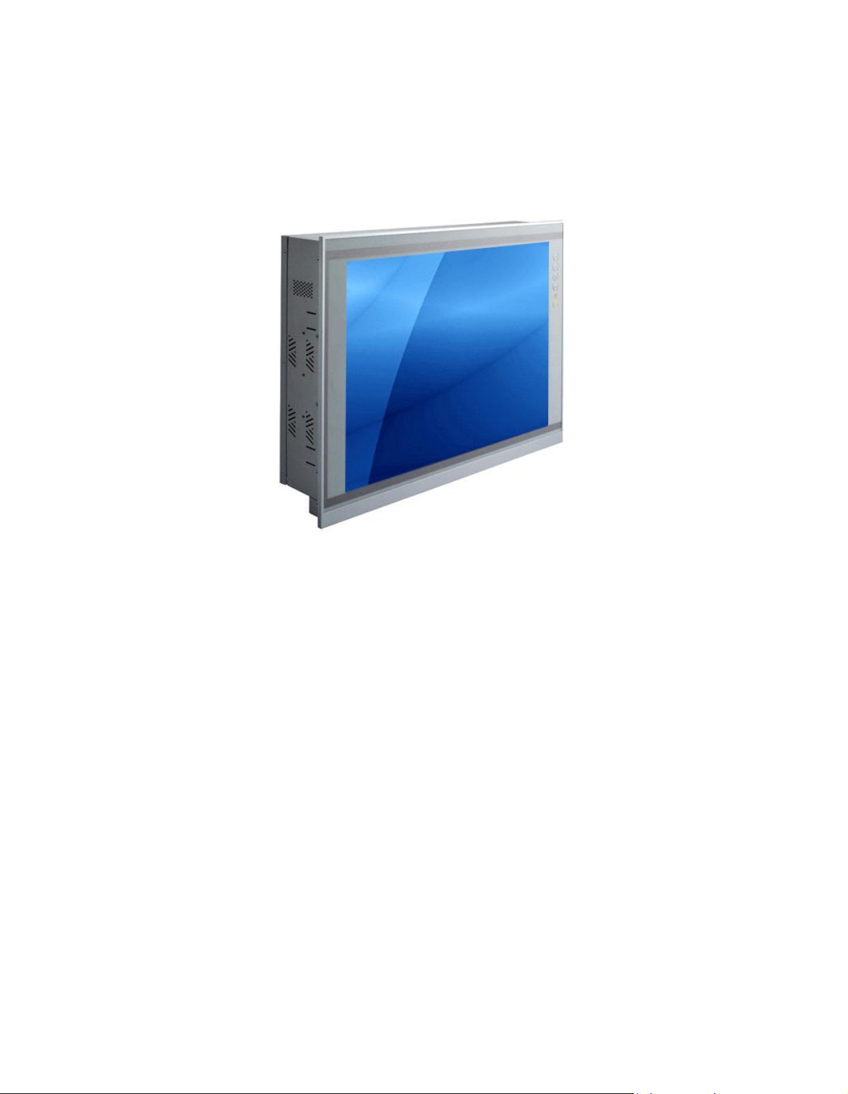
1.1 Ge neral Description
The PC8177 adopts a 17-inch SXGA TFT LCD with 380-nits brightness and
3rd&2nd Core i7/i5/i3 series, Pentium
chipset to provide excellent and powerful computing performance. Furthermore, PC8177
adopts built-in speaker and option WLAN module for wireless connectivity.
®
and Celeron
®
processors and C216/Q77
Industrial-grade front bezel
PC8177 adopts in dustrial-grade material front bezel which incorporates the advantages of light
weight, high degree of hardness better heat releasing, easy-to-shape and anti-corrosion
ability. Therefore, PC8177 is especially suitable for most rugged industrial environments.
Speaker and WLAN Antenna Supported
PC8177 features built-in speakers for kiosk application to display multimedia content
program. It also supports WLAN module (optional) antenna for wireless network connectivity.
Page 7

Powerful computing: 3rd Generation Core i7/i5/i3/Celeron processors
PC8177 features 3
rd &2nd
Core™ i7/i5/i3 series, Pentium
®
and Celeron
®
processors and
C216/Q77 chipset which deliver high computing performance capability. Ivy Bridge CPU
offers reliable and stable performance and rugged environment.
1.2 Specifications
Main CPU Board
CPU
3rd&2nd Core™ i7/i5/i3 series, Pentium® and Celeron® processors
System Chipset
C216/Q77 Express Chipset
System Memory
2 x 204-pin DDR3 1600/1333 MHz SO-DIMM socket
Supporting 8GB per dimm, maximum memory up to 16GB
BIOS
America Megatrends BIOS
I/O System
Standard I/O
1 x RS-232/422/485 with 5V&12V, 1 x RS-232 with 5V/12V, 2 x RS-232
4 x USB 3.0
2 x USB 2.0
1 x HDMI
1 x DVI-I
Ethernet
2 x RJ45 for Giga Ethernet
Audio
1 x Line-out
1 x Mic-in
Expansion
1 x Wireless Module(optional)
Storage
2 x 2.5” or 1 x 3.5” SATA HDD
Power connector
1 x AC plug
Page 8

System Specification
17” SXGA(1280 X 1024)LCD
5 wired resistive Touch
IP65/NEMA4 aluminum front bezel
IP65 aluminum front bezel
Net Weight
7 Kgs (15.43 lb)
Dimension (Main Body Size)
410 x 80 x 338mm
Operation Temperature
0? to 45?
Relative Humidity
10% to 95% @ 40? , Non-Condensing
Power Input
100~240VAC power connector
NOTE 1. All specifications and images are subject to change without notice.
2. Combo key: Pressing Brightness+ & Br ightness- means System ON/OFF.
Pressing VOL+ & VOL- means voice mute.
Page 9
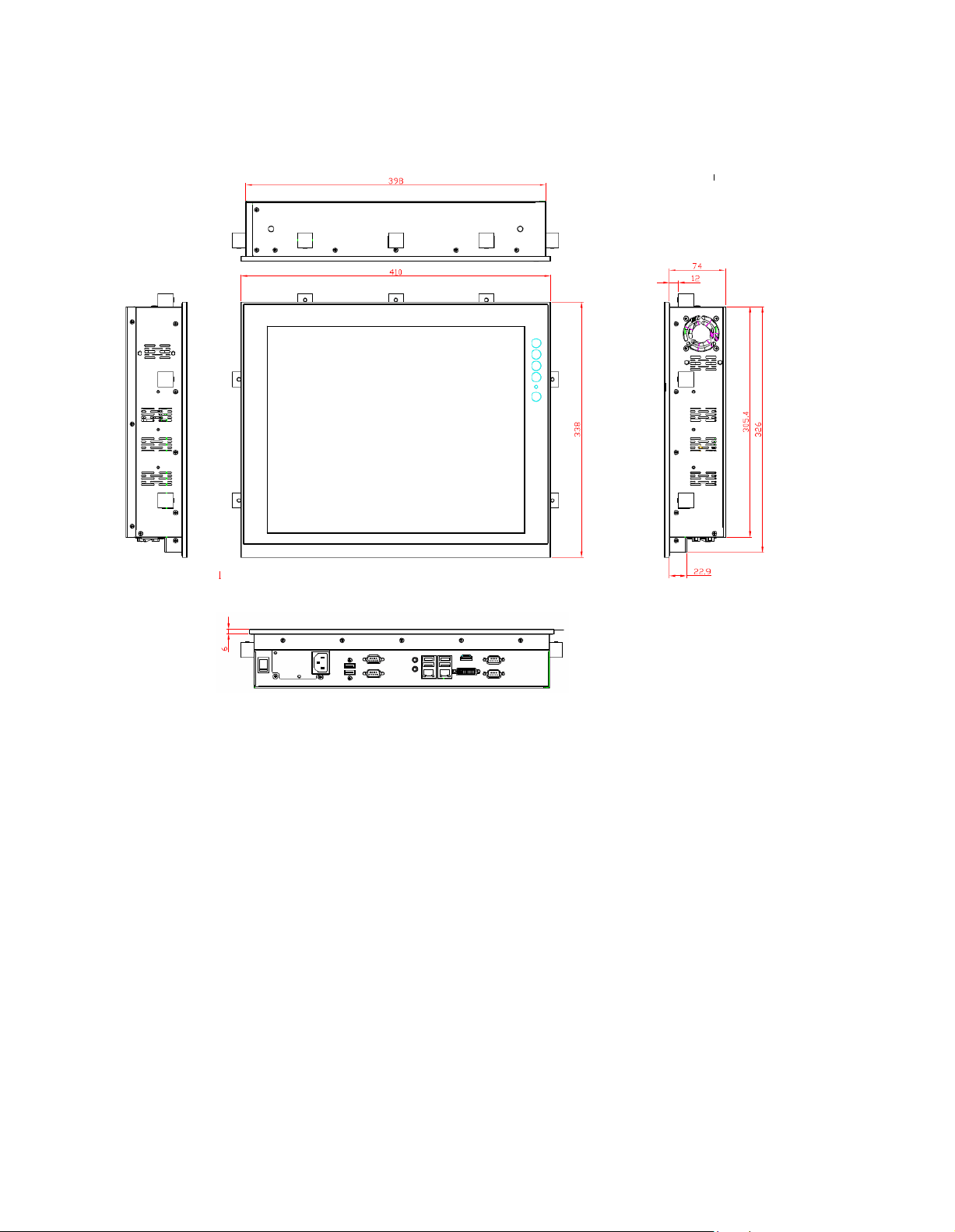
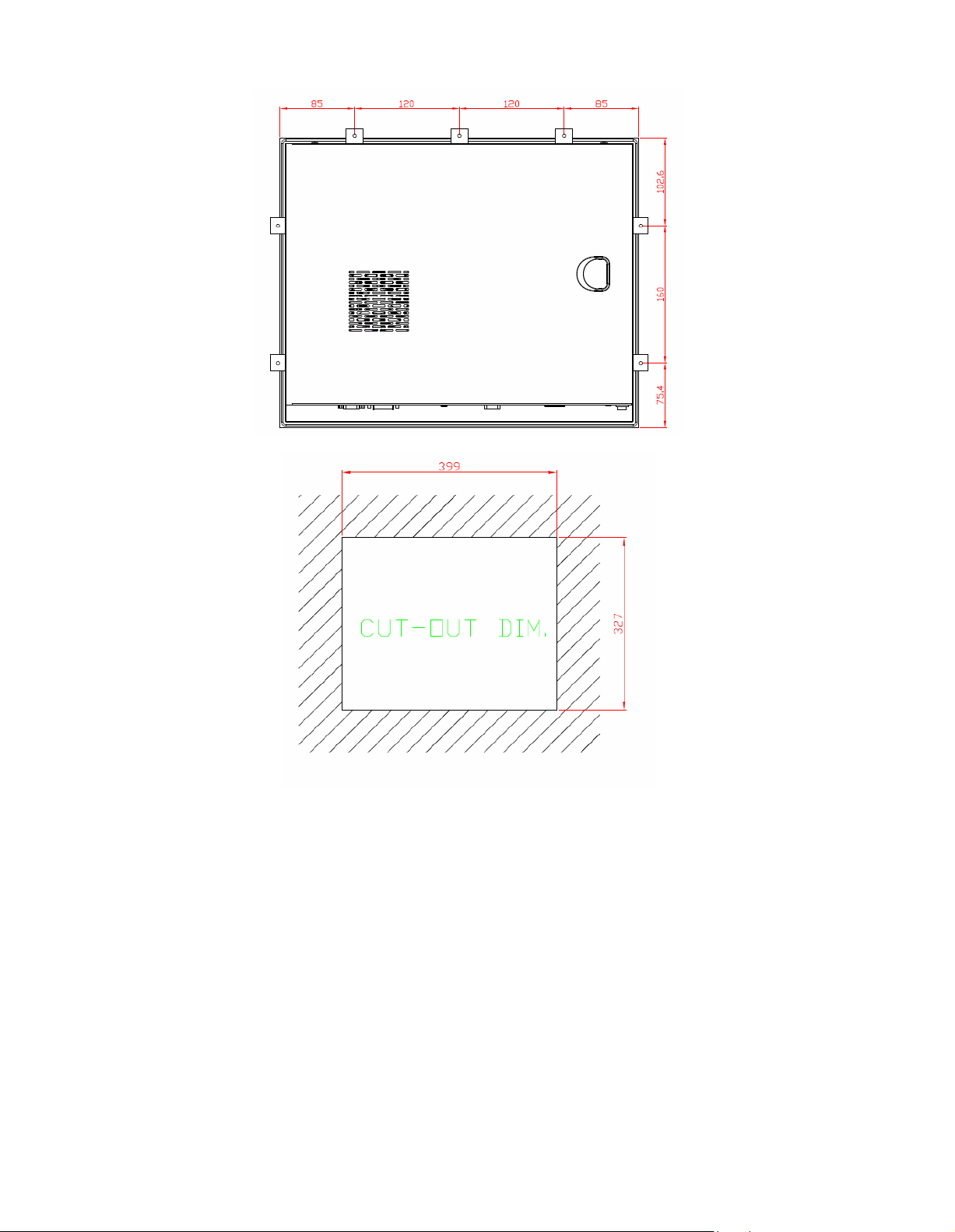
1.3 Dimensions and Outlines
The following diagrams show the dimensions and outlines of PC8177.
Page 10
Page 11
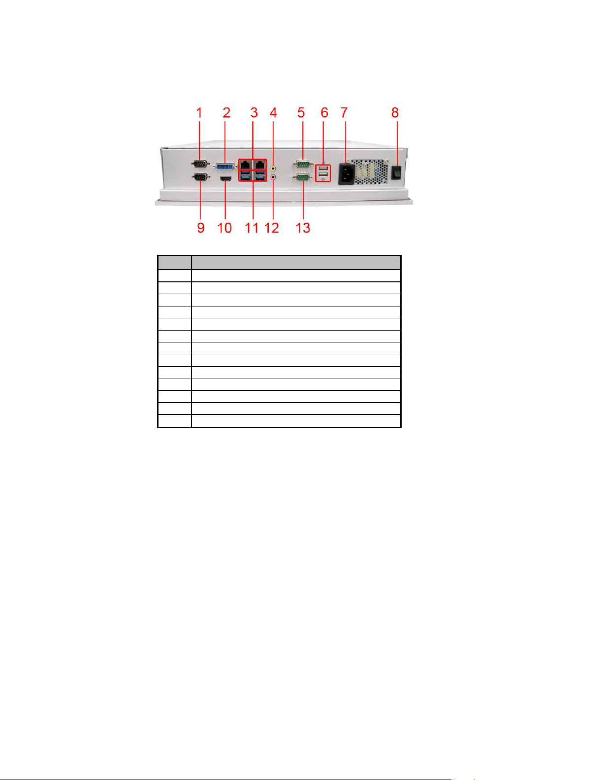
1.4 I/O Outlets
No
Function
1 1 x RS-232/422/485 with 5V&12V (COM1)
2 1 x DVI-I
3
2 x RJ45 for GIGA Ethernet
4 1 x Line-out
5
1 x RS-232 with 5V&12V (COM3)
6 2 x USB2.0
7 1 x AC Plug
8
1 x switch for power on/off
9 1 x RS-232 (COM2)
10
1 x HDMI
11 4 x USB3.0
12 1 x MIC-in
13
1 x RS-232 (COM4)
Please refer to the following illustration for I/O locations of the PC8177.
Page 12

1.5 Packing List
When you receive the PC8177, the bundled package should contain the following items:
PC8177unit x 1
Driver CD x1
Panel mount kit x 6
Wall/VESA mount kit x 1 (optional)
Rack mount kit x 1 (optional)
Power cord x 1
DVI to VGA adaptor
Fan Tunnel x 1
If you cannot find the package or any items are missing, please contact Acnodes distributors
immediately.
Page 13

Chapter 2
Hardware and Installation
The PC8177provides rich I/O ports and flexible expansions for you to meet different
demand. The chapter will show you how to install the hardware. It includes:
Open back cover
Serial Port Interface
Ethernet
Mounting Method
Hard disk
DRAM
CPU
CPU Cooler
Wireless LAN Module(optional)
Fan Tunnel
Page 14

2.1 Ope n back cover
This section tells users how to open back cover. Please follow the steps below.
Step 1 Unscrew 3 screws on the back cover and push to the right side. Please refer
Step 2 Remove the back cover.
the photo below.
Page 15
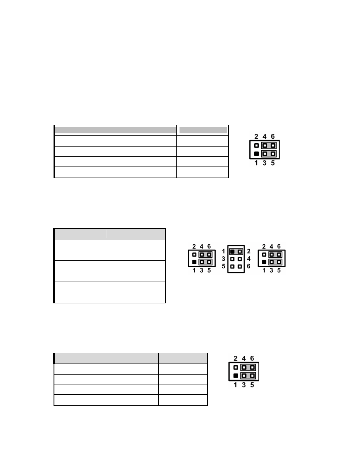
Jumper Setting
Description
Power: Set CN15A pin 1 to +5V level
1-3 close
Data: Set CN15A pin 1 to DCD (Default)
3-5 close
ower: Set CN15A pin 9 to +12V level
2-4 close
Data: Set CN15A pin 9 to RI (Default)
4-6 close
Description
Jumper Setting
RS-232 mode
(Default)
JP11 3-5, 4-6 close
JP12 1-2 close
JP14 3-5, 4-6 close
RS-422 mode
JP11 1-3, 2-4 close
JP12 3-4 close
JP14 1-3, 2-4 close
RS-485 mode
JP11 1-3, 2-4 close
JP12 5-6 close
JP14 1-3, 2-4 close
2.2 Seria l Ports Interface
Description
Jumper Setting
Power: Set CN13 pin 1 to +5V level
1-3 close
Data: Set CN13 pin 1 to DCD (Default)
3-5 close
Power: Set CN13 pin 8 to +12V level
2-4 close
Data: Set CN13 pin 8 to RI (Default)
4-6 close
The PC8177 has four serial ports. COM1 is RS-232/422/485, while COM2, COM3 and
COM4 are RS-232.
The following table shows you the pin assignments of this connector:
2.2.1 COM1 Data/Pow er Selection (JP10)
The COM1 port has +5V level power capability on DCD and +12V level on RI by setting
this jumper. When COM1 is set to +5V or +12V level, please make sure the
communication mode is RS-232 (see section 2.2.2).
2.2.2 COM1 RS-232/422/485 Mode Setting (JP11, JP12, JP14)
Use these jumpers to set COM1 port to operate as RS-232, RS-422 or RS-485
communication mode.
JP11 JP12 JP14
JP10
2.2.3 COM3 Data/Pow er Selection (JP13)
The COM3 port has +5V level power capability on DCD and +12V level on RI by setting
this jum per.
Page 16
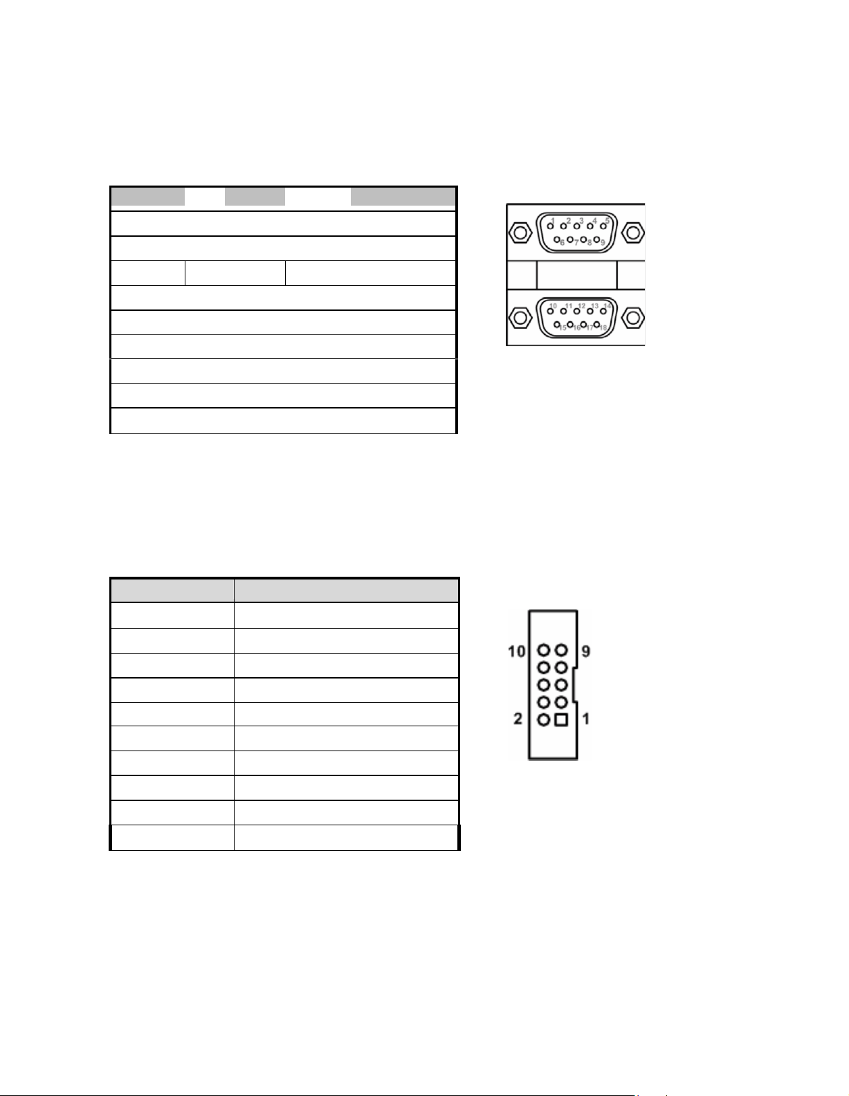
Pin
Pin Signal
1
10
Data Carrier Detect (DCD)
2
11
Receive Data (RXD)
3
12
Transmit Data (TXD)
4
13
Data Terminal Ready (DTR)
5
14
Ground (GND)
6
15
Data Set Ready (DSR)
7
16
Request to Send (RTS)
8
17
Clear to Send (CTS)
9
18
Ring Indicator (RI)
Pin
Signal
1
Data Carrier Detect (DCD)
2
Data Set Ready (DSR)
3
Receive Data (RXD)
4
Request to Send (RTS)
5
Transmit Data (TXD)
6
Clear to Send (CTS)
7
Data Terminal Ready (DTR)
8
Ring Indicator (RI)
9
Ground (GND)
10
NC
2.2.4 COM1&COM2 C onnector
The CN15 is a double-deck DB-9 connector. The upper connector (CN15A) is for COM1
and the lower connector (CN15B) is for COM2. Note that the connectors (CN13 and
CN15A) come with power capability on DCD and RI pins by setting jumpers (see section
2.2.1).
CN15A (COM1)
CN15B (COM2)
2.2.5 COM3 & COM4 C onnectors
The COM3 and COM4 i nterfac es are av aila ble through CN13 an d CN14,
r espec tiv ely. Eac h o f thes e c onnec tors is a 2x 5 pi n 2.0 pitc h b ox header, see
table bel ow for its pin a ss ignm ents .
CN13/CN14
Page 17
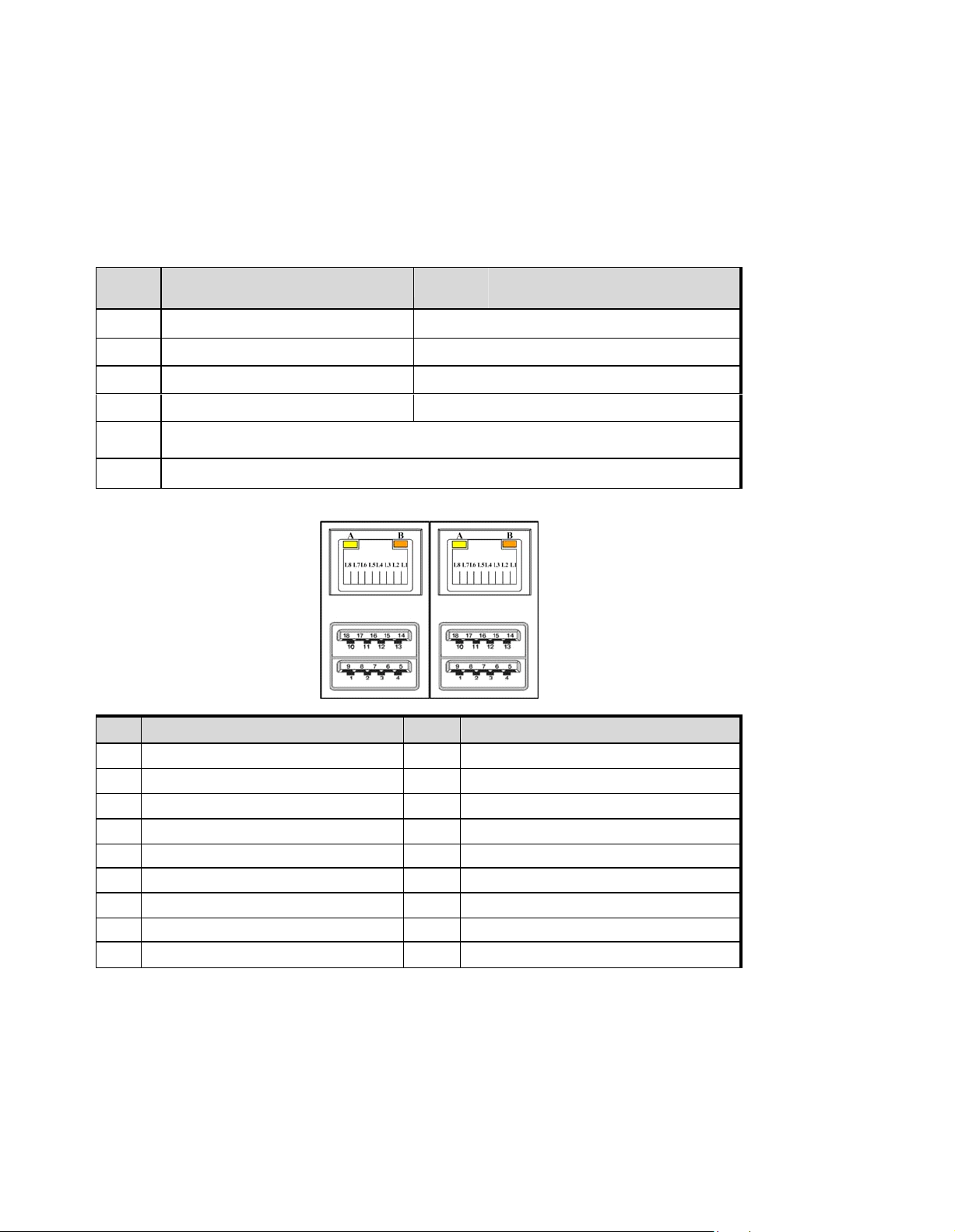
2.3 Etherne t
Pin
LAN1 Signal (WG82579LM)/
LAN2 Signal (WG82583V)
Pin
LAN1 Signal (WG82579LM)/
LAN2 Signal (WG82583V)
L1
MDI0+
L5
MDI2+
L2
MDI0-
L6
MDI2-
L3
MDI1+
L7
MDI3+
L4
MDI1-
L8
MDI3-
A
100 LAN LED (Green)/
1000 LAN LED (Orange)
B
Active LED
Pin
USB Signal
Pin
USB Signal
1
USB_VCC(+5V level standby power)
10
USB_VCC (+5V level standby power)
2
USB_Data2-
11
USB_Data3-
3
USB_Data2+
12
USB_Data3+
4
GND
13
GND
5
SSRX2-
14
SSRX3-
6
SSRX2+
15
SSRX3+
7
GND
16
GND
8
SSTX2-
17
SSTX3-
9
SSTX2+
18
SSTX3+
The PC8177 is equipped with two high performance plug and play Ethernet interfaces
(RJ-45) which are fully compliant with the IEEE 802.3 standard. Connection can be
established by plugging one end of the Ethernet cable into this RJ-45 connector and the other
end to a 1000/100/10-Base-T hub.
The Universal Serial Bus (compliant with USB 3.0 (5Gb/s)) connectors on the rear I/O are for
installing USB peripherals such as keyboard, mouse, scanner, etc. Note that the CN10 carries
LAN1, USB 3.0 port 2 and 3 signals while CN11 carries LAN2, USB 3.0 port 0 and 1 signals
CN10 CN11
Page 18
2.4 Mountings: Panel / Wall / Rack / Desktop / VESA
There are 5 application options for the PC8177, including Panel/Wall/Rack/ Desktop/VESA
mounting ways.
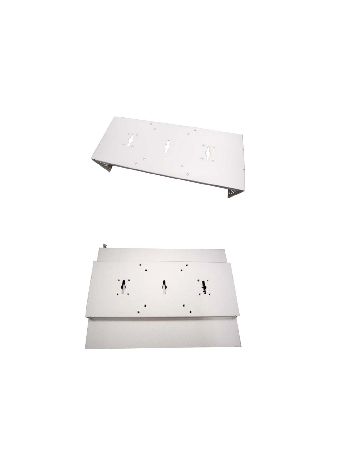
2.4.1 VESA-ARM / Wall-Mount / Desktop-mount
The PC8177provides VESA mount: 75x75 mm or 100x100mm. Screw six screws to
fix the kit in the back chassis.
^ VESA/ Wall mount bracket
^ Putting the bracket on the back of system
Page 19

? Fixing the bracket by six screws on the left and right side.
2.4.2 Panel-mount Kit Assembl y
The PC8177is designed for panel mount application. To mount the PC8177, the
standard set of mounting k it (included in the system packaging) is needed.
Page 20

2.4.3 Rack-mount Kit Assembly
The PC8177is designed for rack mount application. To mount the PC8177, the
standard set of mounting k it (included in the system packaging) is needed.
Step 1 Unscrew the fix screws from the left and right side of the system.
Step 2 Fixing the rack-mount bracket to the left and right of the system.
Page 21

2.5 HDD Installation
The PC8177provides a convenient Hard Disk Drive (HDD) bracket for users to install 2 x
2.5” or 1 x 3.5” SATA HDD. Please follow the steps:
Step 1 Refer section 2.1 to open the back cover.
Step 2 Unscrew 4 screws to take off the HDD bracket.
Step 3 Fix the HDD on bracket by the screws.
? 1 x 3.5” SATA HDD Kit ? 1 x 2.5” or 2 x 2.5” SATA HDD Kit
? Fix the 3.5” HDD on the back of bracket ? Fix the 2.5” HDD on the right and left side of
bracket
Page 22

Step 4 Fix the HDD bracket into the main base.
Step 5 Plug the power and SATA cables to connectors. Installation completes.
Page 23
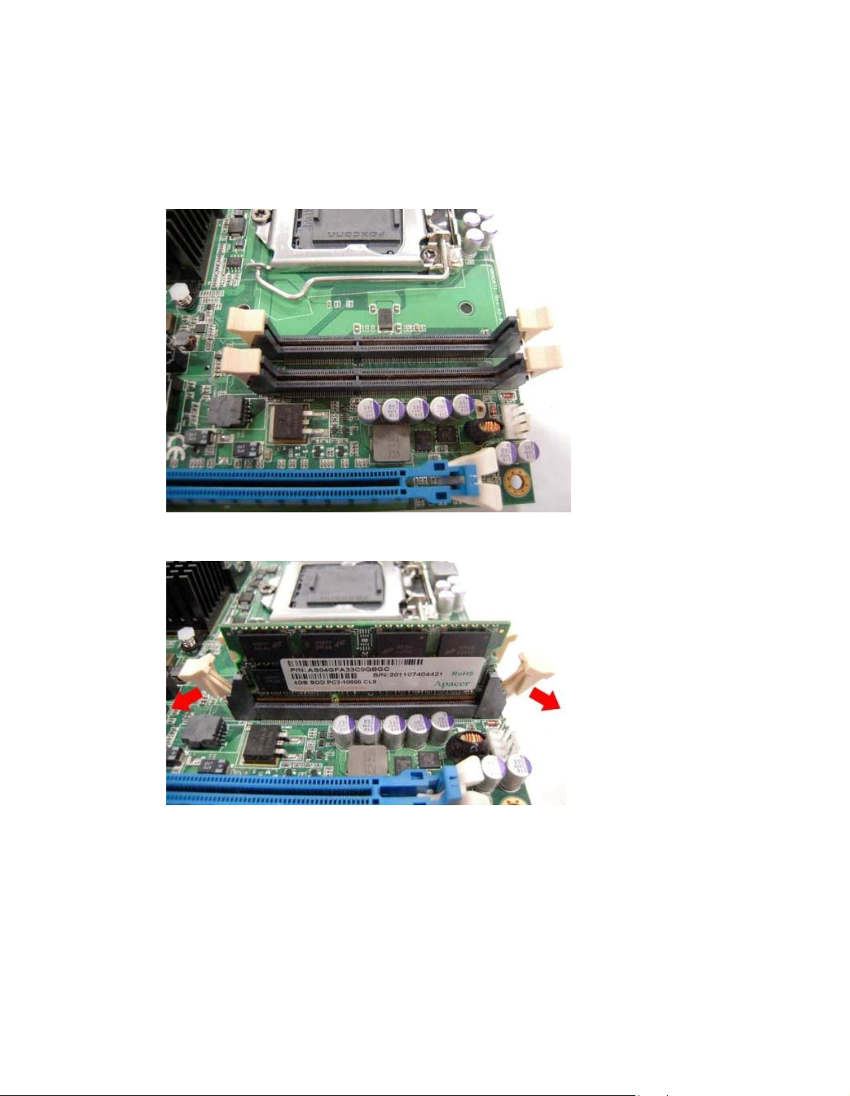
2.6 DR AM Insta llation
The PC8177provides two 204-pin DDR3 SO-DIMM sock et that support system memory up to
16GB. Please follow steps below to install the memory modules:
Step 1 Refer to section 2.1 to open the back cover and find out DIMM socket on
mainboard (MANO871).
Step 2 Push the latches on each side of the SO-DIMM slot down.
Page 24

Step 3 Install the SO-DIMM module into the slot and press it firmly down until it seats
correctly.
Step 4 The slot latches are levered upwards and latch on to the edges of the
SO-DIMM.
Page 25

2.7 CPU Installation
The PC8177has an LGA1155 socket supporting 3rd&2
and Celeron® processors and provides high computing performance for users.
Step 1 Press the hook of lever down with your thumb and pull it to the right side to
release it from retention tab.
nd
Core™ i7/i5/i3 series, Pentium
®
Step 2 Lift the tail of the load lever and rotate the load plate to fully open position.
And, remove the protective plastic cover.
Page 26
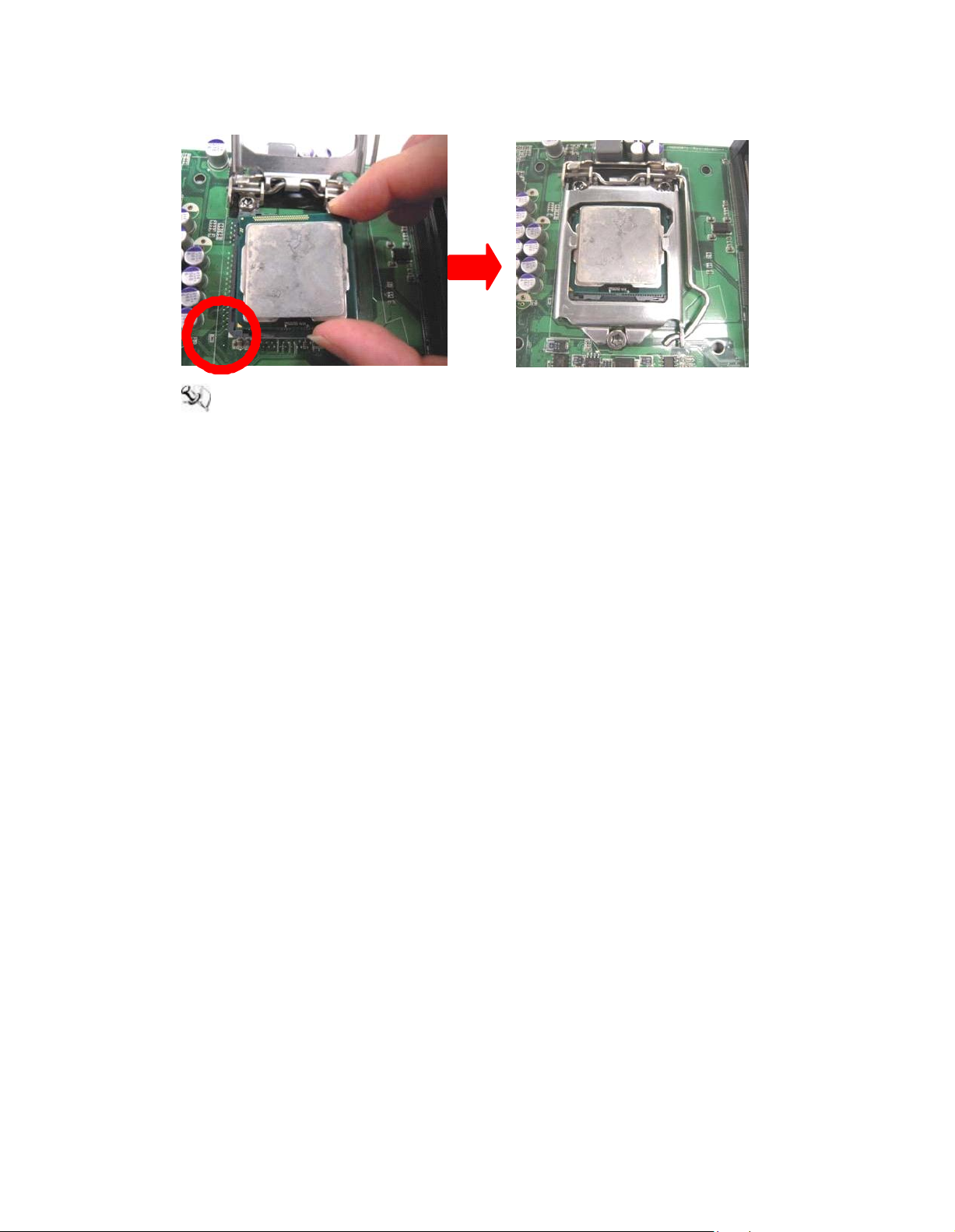
Step 3 CPU aims at the socket and places the package carefully into the socket by
purely vertical motion.
NOTE Never touch fragile socket contacts to avoid damage and do not touch
pr ocessor sensitive contacts at any time during installation.
Page 27

2.8 CPU Cooler In stalla tion
Step 1 Making sure your CPU settled correctly on the socket.
Step 2 Screw the cooling fan supporting base onto the CPU socket on the
Motherboard and make sure the CPU fan is plugged to the CPU fan connector.
And, Connect the CPU cooler power connector to the FAN1 connector
Page 28
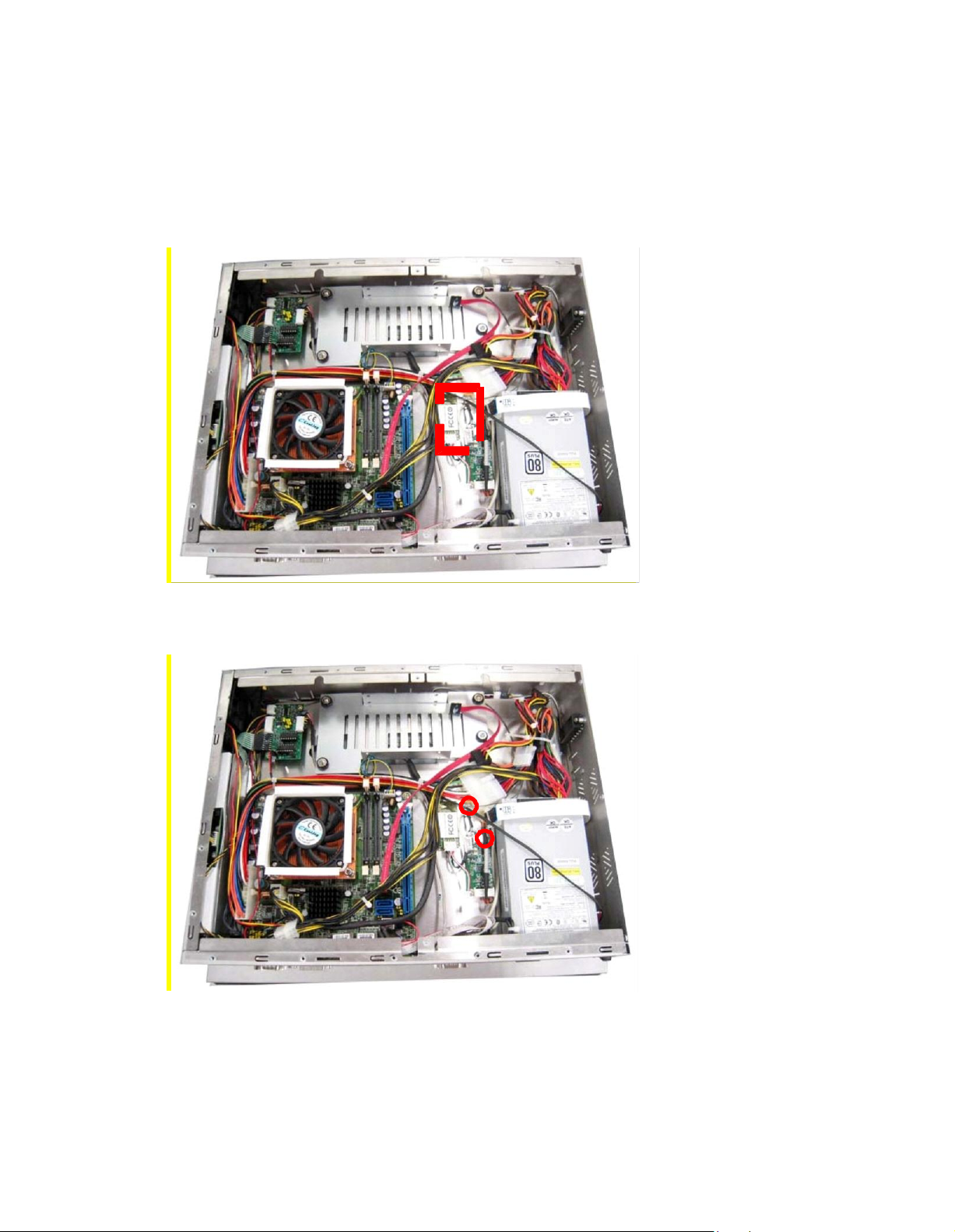
2.9 Wireless L AN Module Installation (optional)
The PC8177 provides one wireless LAN module to install. When installing the wireless
LAN module, refer to the following instructions and illustration:
Step 1 Refer to section 2.1 to open the back cover and find out the wireless LAN
Step 2 Fixing the wireless LAN module by 2 screws.
module located.
Page 29
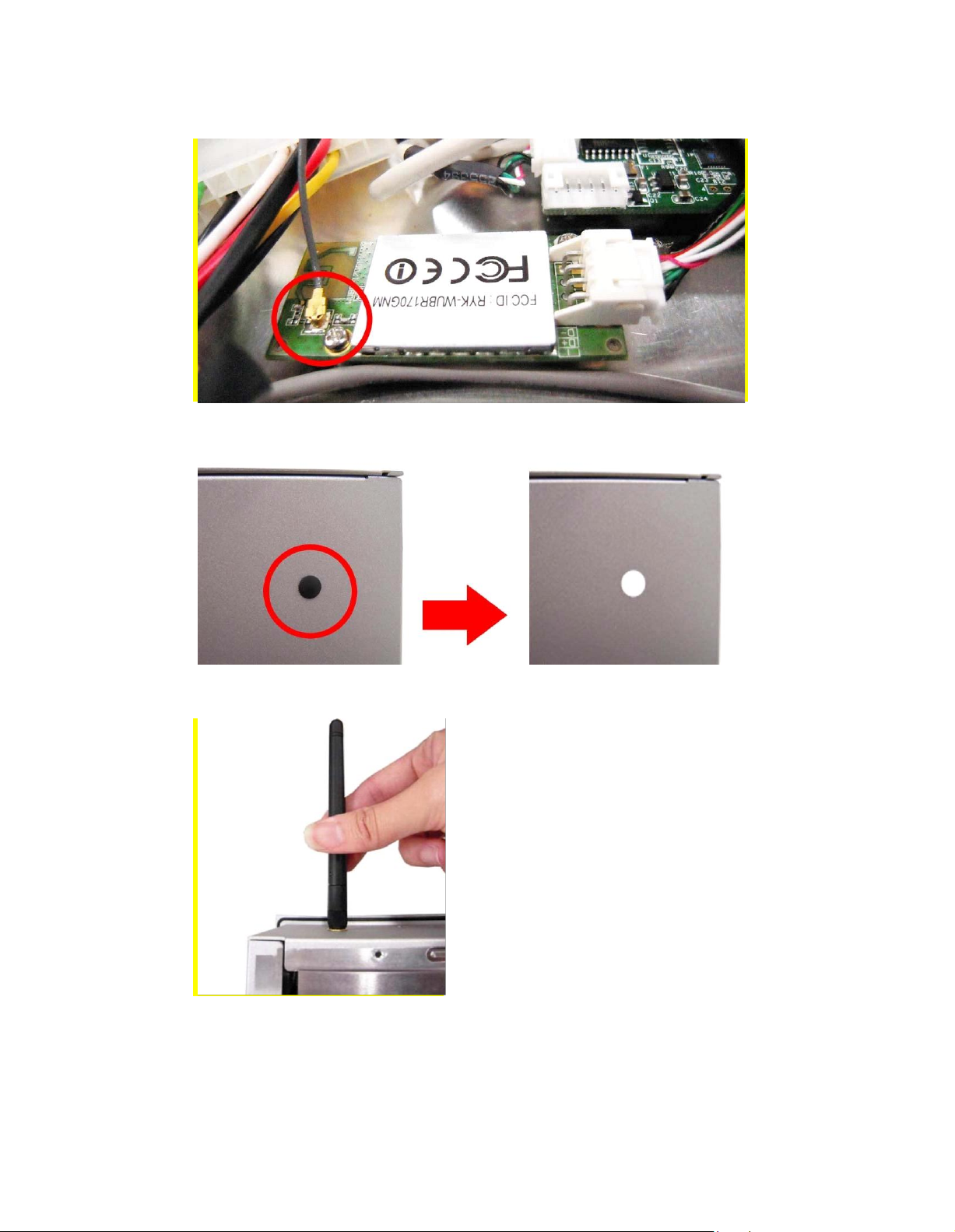
Step 3 Plug in USB cable to the connector of WIFI module. And, find the built-in
Antenna cable and connect it wireless LAN card.
Step 4 Lift the rubber stopper from the top of back cover.
Step 5 Install the antenna on the antenna connector.
Page 30
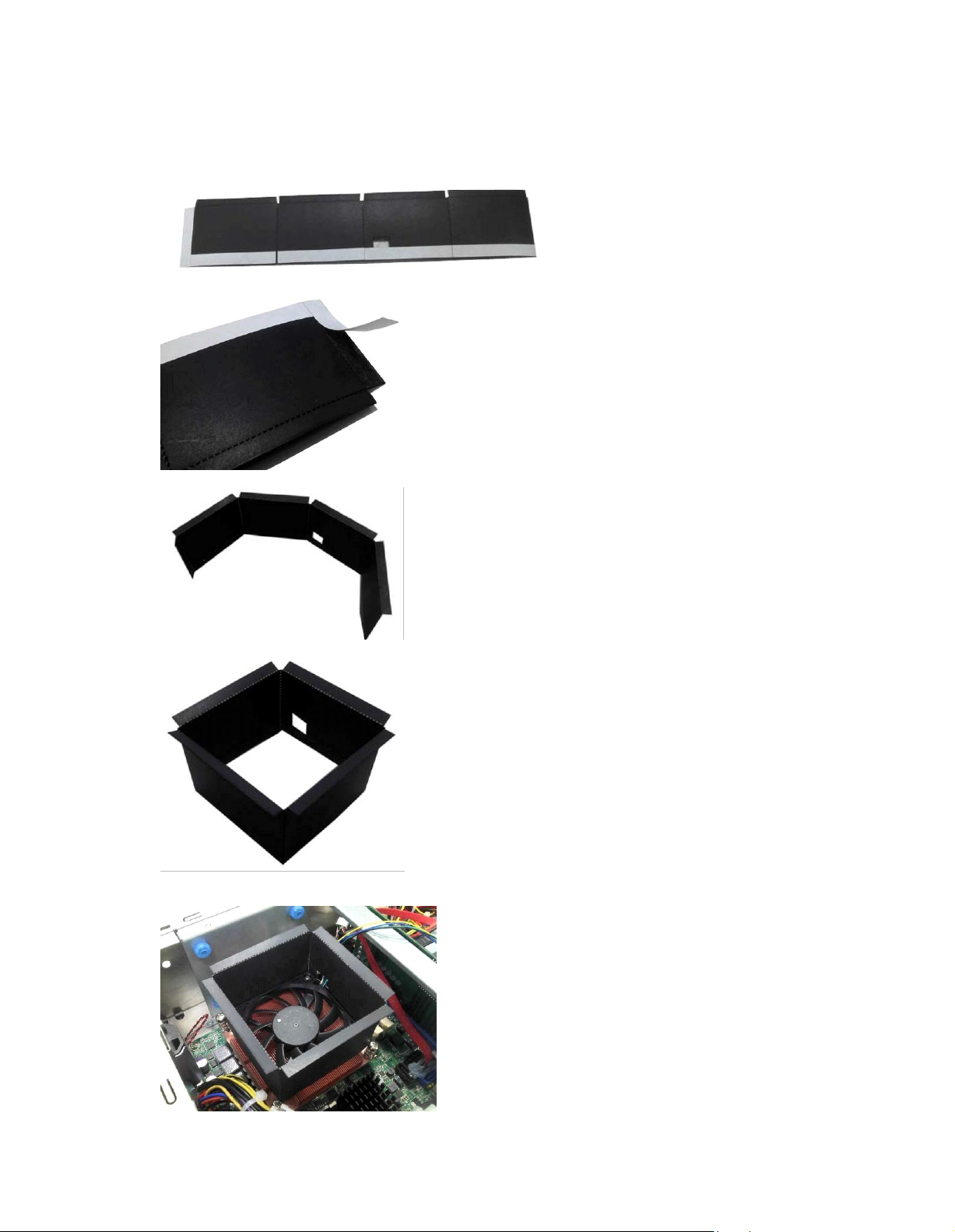
2.10 Fan Tunnel Ins tallation
The PC8177 provides one fan tunnel to install. When installing the fan tunnel, refer to the
following instructions and illustration:
Step1 Spread the fan tunnel out flat.
Step2 Tear the releasing paper from the dual face tape.
Step3 Fold each curved line.
Step4 Stick each side together.
Step5 Let fan cable through the fan tunnel and stick to the cooler.
Page 31

Chapter 3
Hot Keys
Description
Left/Right
The Left and Right <Arrow> keys allow you to select a setup screen.
Up/Down
The Up and Down <Arrow> keys allow you to select a setup screen or
sub-screen.
+ Plus/Minus
The Plus and Minus <Arrow> keys allow you to change the field value of a
particular setup item.
Tab
The <Tab> key allo ws you to select setup fields.
F1
The <F1> key allows you to display the general help screen.
F2
The <F2> key allows you to load previous values.
F3
The <F3> key allows you to load optimized defaults.
F4
The <F4> key allows you to save any changes you have made and exit
setup. Press the <F4> key to save your changes.
Esc
The <Esc> key allows you to discard any changes you have made and exit
the setup. Press the <Esc> key to exit the setup without saving your
changes.
Enter
The <Enter> key allows you to display or change the setup option listed for a
particular setup item. The <Enter> key can also allow you to display the
setup sub- screens.
AMI BIOS Setup Utility
The AMI UEFI BIOS provides users with a built- in setup program to modify basic system
configuration. All configured parameters are stored in a flash chip to save the setup information
whenever the power is turned off. This chapter provides users with detailed description about
how to set up basic system configuration through the AMI BIOS setup utility.
3.1 Starting
To enter the setup screens, follow the steps below:
1. Turn on the computer and press the <Del> key immediately.
2. After you press the <Del> key, the main BIOS setup menu displays. You can access the
other setup screens from the main BIOS setup menu, such as the Advanced and Chipset
menus.
It is strongly recommended that you should avoid changing the chipset’s defaults. Both AMI
and your system manufacturer have carefully set up these defaults that provide the best
performance and reliabil ity
3.2 Navigation Ke ys
The BIOS setup/utility uses a key-based navigation system called hot keys. Most of the BIOS
setup utility hot keys can be used at any time during the setup navigation process. These k eys
include <F1>, <F2>, <Enter>, <ESC>, <Arrow> keys, and so on.
Note: Some of the navigation keys differ from one scr een to another.
Page 32

3.3 Main Menu
When you first enter the Setup Utility, you will enter the Main setup screen. You can always
return to the Main setup screen by selecting the Main tab. There are two Main Setup options.
They are described in this section. The Main BIOS Setup screen is shown below
System Date/Time
Use this option to change the system time and date. Highlight System Time or System Date
using the <Arrow> keys. Enter new values through the keyboard. Press the <Tab> key or the
<Arrow> keys to move between fields. The date must be entered in MM/DD/YY format. The
time is entered in HH:MM:SS format.
Page 33

3.4 Adva nced Menu
The Advanced menu also allows users to set configuration of the CPU and other system
devices. You can select any of the items in the left frame of the screen to go to the sub menus:
ACPI Settings
Trusted Computing
CPU Configuration
SATA Configuration
PCH-FW Configuration
AMT Configuration
USB Configuration
NCT6627UD Super IO Configuration
For items marked with “”, please press <Enter> for more options.
NCT6627UD HW Monitor
Page 34

ACPI Settings
You can use this screen to select options for the ACPI Configuration, and change the value
of the selected option. A description of the selected item appears on the right side of the
screen.
ACPI Sleep State
Select the highest ACPI sleep state the system will enter when the suspend button is pressed.
Configuration options are Suspend Disabled, S1 only (CPU Stop Clock), and S3 only
(Suspend to RAM).
To correctly support wake by use of USB from the S3 system power state, please refer to the
following Microsoft’s link:
http://support.microsoft.com/kb/841858/en-us
Page 35

Trusted Computing
This screen provides function for specifying the TPM settings.
Security Device Support
Use this item to enable or disable BIOS support for security device.
Security Device Support
Display current TPM status information.
Page 36
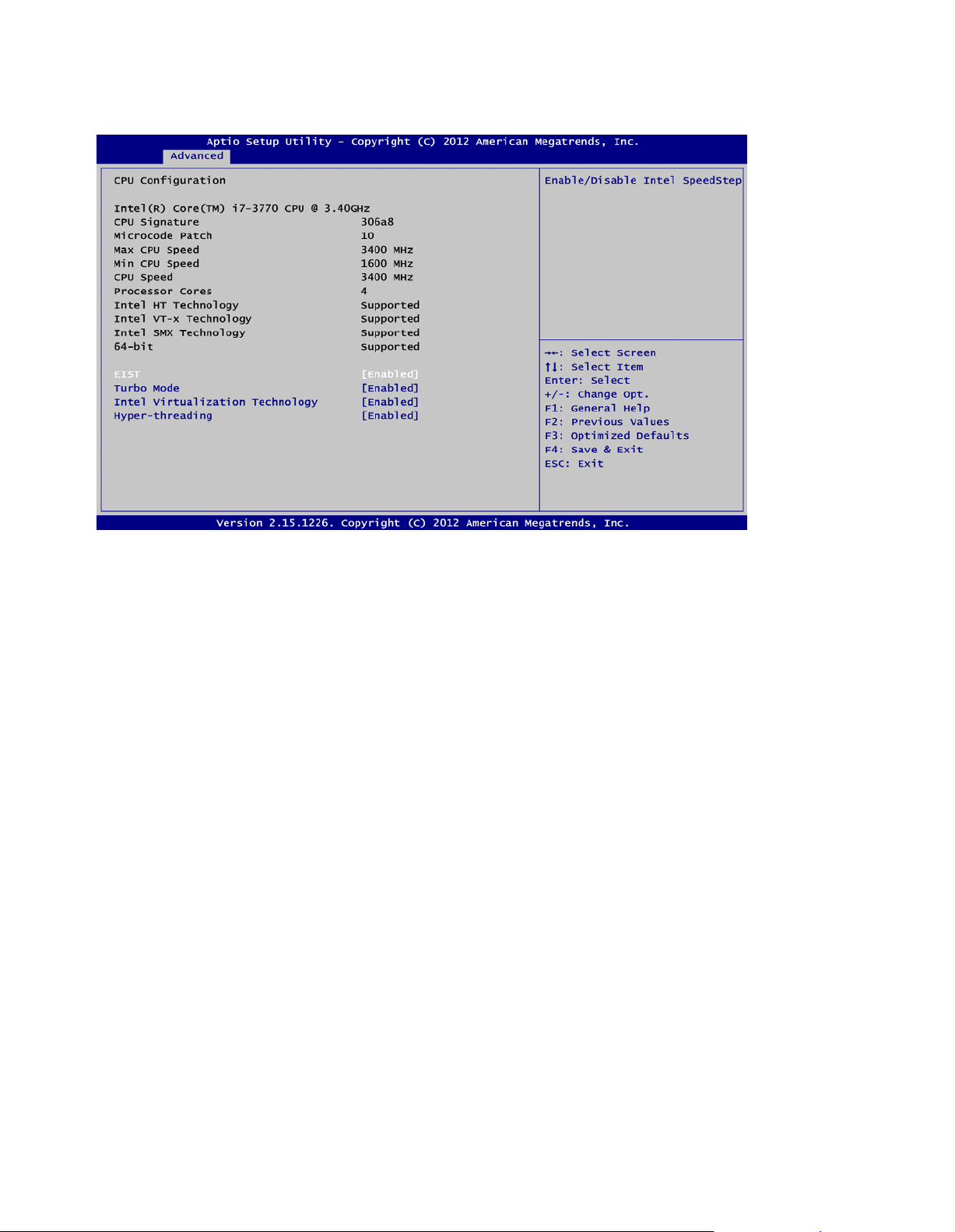
CPU Configuration
This screen shows the CPU information.
EIST
Enable or disable Speed Step. When enabled, CPU speed is controlled by the operating
system. When disabled, CPU runs at its default speed.
Turbo Mode
This item is for enabling or disabling turbo mode. When enabled, it allows processor cores to
run faster than marked frequency under certain conditions.
Intel Virtualization Technology
This item allows a hardware platform to run multiple operating systems separately and
simultaneously, enabling one system to virtually function as several s ystems.
Hyper-threading
Use this item to enable or disable Hyper-Threading Technology, which makes a single physical
processor perform multi-tasking function as two logical ones.
Page 37

SATA Configuration.
In this Configuration menu, you can see the currently installed hardware in the SATA ports.
During system boot up, the BIOS automatically detects the presence of SATA devices.
SATA Controller(s)
Enable or disable SATA device.
SATA Mode Selection
Determine how SATA controller(s) operate. Operation mode options are: IDE Mode, AHCI
Mode and RAID Mode.
Page 38
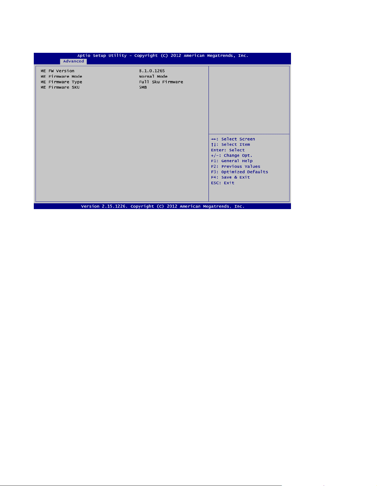
PCH-FW Configuration
This screen displa ys Management Engine (ME) Firm ware information.
Page 39

AMT Configuration
Use this screen to configure AMT parameters.
Intel AMT
Enable or disable Active Management Technology BIOS Extension.
Disable ME
Enable or disable ME functionality.
Page 40

USB Configuration
You can use this screen to sele ct options for the USB Configuration, and change the value of
the selected option. A description of the selected item appears on the right side of the screen.
USB Devices
Display all detected USB devices.
Legacy USB Support
Use this item to enable or disable support for USB device on legacy operating system. The
default setting is Eenabled. Auto option dis ables legacy support if no USB devices are
connected. Disable option will keep USB devices available only for EFI applications.
Page 41

NCT6627UD Super IO Configuration
You can use this screen to select options for the Super IO Configuration, and change the value
of the selected option. A description of the selected item appears on the right side of the
screen. For items marked with “>”, please press <Enter> for more options.
Serial Port 1~4 Configuration
Use this item to set parameters of serial port 1 to 4.
Page 42
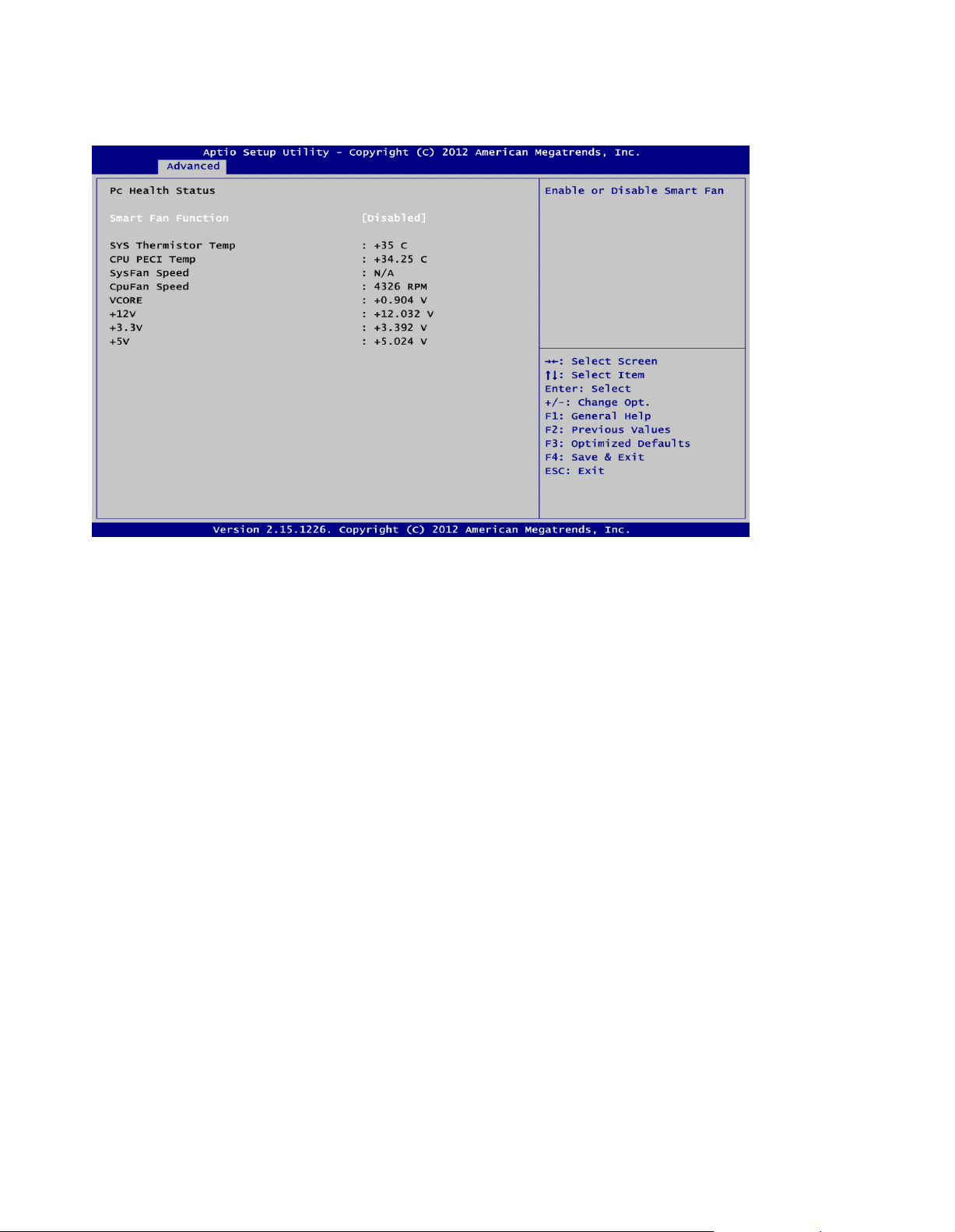
NCT6627UD HW Monitor
Use this screen for Smart Fan configuration and hardware health status monitoring.
This screen displays the temperature of system and CPU, cooling fan speed in RPM and
system voltages (VCORE, +12V, +3.3V and +5V).
Smart Fan Function
Enable or disable Smart Fan function.
Page 43

3.5 Chipset Menu
The Chipset menu allows users to change the advanced chipset settings. You can select any
of the items in the left frame of the screen to go to the sub menus:
PCH-IO Configuration
System Agent (SA) Configuration
For items marked with “>”, please press <Enter> for more options.
Page 44

PCH-IO Configuration
This screen allows you to set PCH parameters.
USB Configuration
Use this item for USB configuration settings.
PCH Azalia Configuration
Use this item for PCH Azalia configuration settings.
Launch PXE OpROM policy
Control the execution of UEFI and Legacy PXE OpROM.
PCH LAN Controller
Enable or disable PCH LAN controller.
Wake on LAN
Enable or disable Wake on LAN functionality.
Page 45
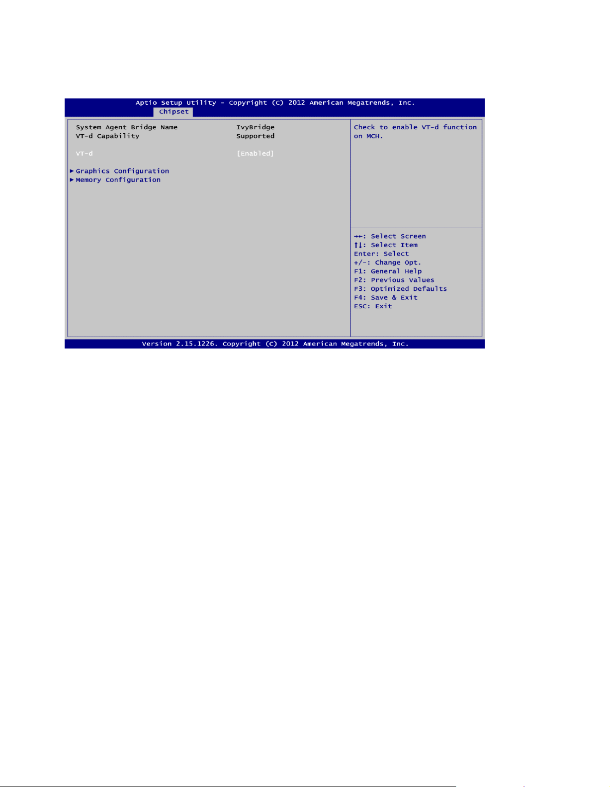
System Agent (SA) Configuration
This screen shows System Agent information and provides function for specifying related
parameters. For items marked with “>”, please press <Enter > for more options.
VT-d
Enable or disable chipset virtualization technology for directed I/O. VT-d can help end users
improve security and reliability of the systems and also improve performance of I/O
devices in virtualized environment.
Graphics Configuration
Use this item for graphics configuration settings.
Memory Configuration
Use this item for memory configuration settings.
Page 46
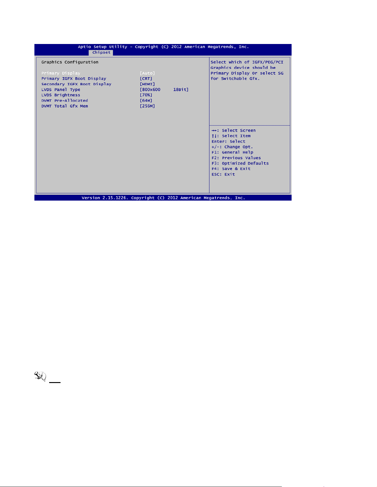
Graphics Configuration
Primary Display
Allow you to select which graphics controller to use as the primary boot device.
Primary IGFX Boot Display
Allow you to select the display device which will be activated during POST. This has no effect if
external graphics present. Secondary boot display selection will appear based on your
selection. Primar y IGFX boot display options are: CRT, DVI, LVDS and HDMI.
Secondary IGFX Boot Display
Use this item to select secondary display device. Secondary IGFX boot display options are:
CRT, DVI, LVDS and HDMI.
LVDS Panel Type
Use this item to select LVDS panel used by internal graphics controller by selecting the
appropriate setup item.
LVDS Brightness
Select LVDS brightness that ranges from 30% to 100%. The default setting is 70%.
DVMT Pre- Allocated
Select DVMT pre-allocated memory size.
DVMT Total Gfx Mem
Select DVMT total memory size.
Note: BIOS will default LVDS & CRT display.
Page 47
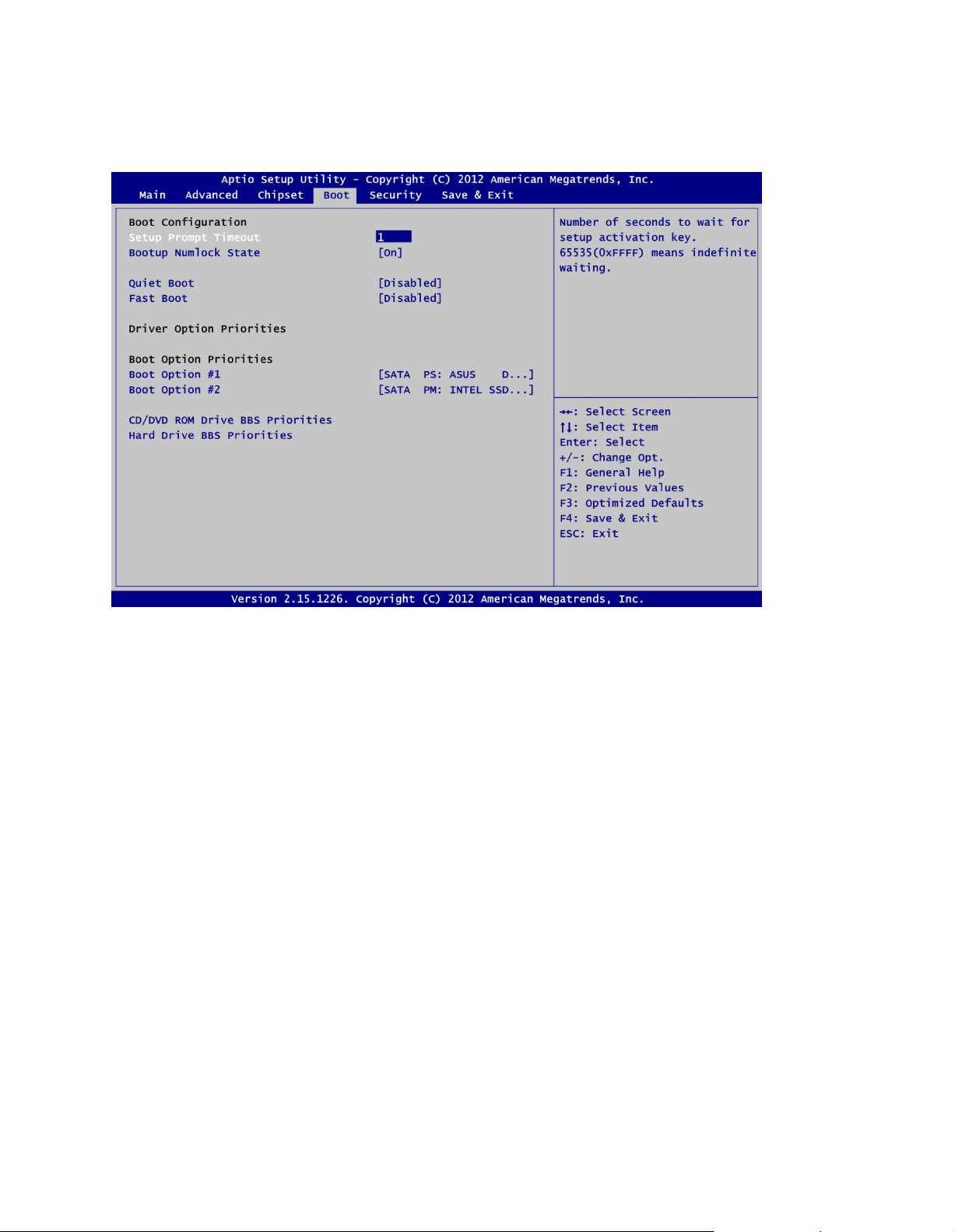
3.6 Boot Menu
The Boot menu allows users to change boot options of the system.
Setup Prompt Timeout
Number of seconds to wait for setup activation key. 65535(0xFFFF) means indefinite waiting.
Bootup NumLock State
Use this item to select the power-on state for the keyboard NumLock.
Quiet Boot
Select to display either POST output messages or a splash screen during boot-up.
Fast Boot
Enable or disable boot with initialization of minimal set of devices required to launch active
boot option. Has no effect for BBS boot options.
Boot Option Priorities
These are settings for boot priority. Specify the boot device priority sequence from the
available devices.
Boot Option #1..#2
These items are used to form the boot order and are dynamically generated. They represent
either a legacy BBS (BIOS Boot Specification) class of devices or a native EFI boot entry.
Press <Return> on each option to select the BBS class / EFI boot entry desired
CD/DVD ROM Drive BBS/Hard Drive BBS Priorities
These items are for configuring the boot order for a s pecific device class. These options are
only visible if at least one device for this class is detected.
Page 48

3.7 Security Menu
The Security menu all ows users to change the security settings for the system.
Administrator Password
This item indicates whether an administrator password has been set (installed or uninstalled).
User Password
This item indicates whether an user pass word has been set (installed or uninstalled).
Page 49

3.8 Save & Exit Menu
The Save & Exit menu allows users to load your system configuration with optimal or fail-safe
default values.
Save Changes and Exit
When you have completed the system configuration changes, select this option to leave Setup
and reboot the computer so the new system configuration parameters can take effect. Select
Save Changes and Exit from the Exit menu and press <Enter>. Select Ok to save changes
and exit.
Discard Changes and Exit
Select this option to quit Setup without making any permanent changes to the system
configuration. Select Discard Changes and Exit from the Exit menu and press <Enter>. Select
Ok to discard changes and exit.
Save Changes and Reset
When you have completed the system configuration changes, select this option to leave Setup
and reboot the computer so the new system configuration parameters can take effect. Select
Save Changes and Reset from the Save & Exit menu and press <Enter>. Select Yes to save
changes and reset.
Discard Changes and Reset
Select this option to quit Setup without making any permanent changes to the system
configuration and reboot the computer. Select Discard Changes and Reset from the Save &
Exit menu and press <Enter>. Select Yes to discard changes and reset.
Save Changes
When you have completed the system configuration changes, select this option to save
changes. Sel ect Save Changes from the Save & Exit menu and press <Enter>. Select yes to
save changes.
Page 50

Discard Changes
Select this option to quit Setup without making any permanent changes to the system
configuration. Select Discard Changes from the Save & Exit menu and press <Enter>. Select
Yes to discard changes.
Restore Defaults
It automatically sets all Setup options to a complete set of default settings when you select this
option. Select Restore Defaults from the Save & Exit m enu and press <Enter>.
Save as User Defaults
Select this option to save system configuration changes done so far as User Defaults. Select
Save as User Defaults from the Save & Exit menu and press <Enter>.
Restore User Defaults
It automatically sets all Setup options to a complete set of User Defaults when you select this
option. Select Restore User Defaults from the Save & Exit menu and press <Enter>.
Launch EFI Shell from filesystem device
Attempt to launch EFI Shell application (Shellx64.efi) from one of the available filesystem
devices.
Page 51
Chapter 4
Touch Screen
5-wire Analog Resistive type
Touch Screen Controller
PenMount 6500 USB Touch Screen Controller IC
Communications
USB interface
Baud Rate
19200 baud rate fixed
Resolution
1280 X 1024
Drivers Installation
4.1 S ystem
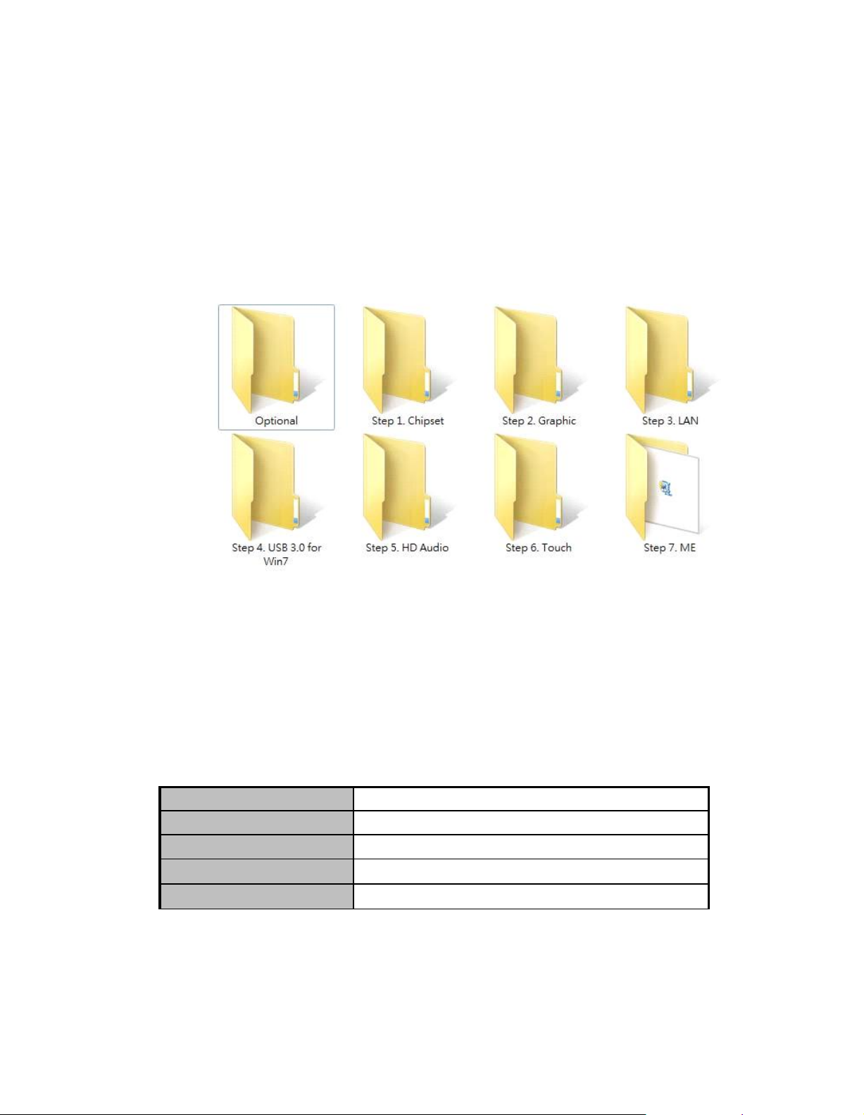
PC8177supports Windows 7 and WES 7. To facilitate the installation of system driver,
please carefully read the instructions in this chapter before start installing.
Step 1 Insert Driver CD and select the “\Drivers”.
Step 2 Select all files and follow the installing procedure.
4.2 Touch Scre en
The PC8177uses the 5-wire analog resistive. There are the specification and driver
installation which are listed below.
Specification
Page 52

Driver Installation- Windows 7
The PC8177provides a touch screen driver that users can install it under the operating
system Windows 7. To facilitate installation of the touch screen driver, you should read the
instructions in this chapter carefully before you attempt installation.
Step 1 Insert Driver CD and follow the path to select the “\Drivers\Step 6. Touch”.
Step 2 Follow the installing procedure and press OK.
Step 3 Click Start menu and select “PenMount Utilities”; and then, a “PenMount
Control Panel” pops out.
Page 53

Step 4 Select the “Standard Calibrate” tab.
Step 5 Calibrations:
To adjust the display with touch panel, click “Calibration” and follow the calibrate
point to do calibration; there are five po ints on screen for calibration.
Step 6 Press OK.
Page 54

4.3 Embedde d O.S.
The PC8177provides the Windows 7 Embedded. The O.S. is supported devices which are
listed below.
WES 7
Here are supported onboard devices:
Onboard Mult i I /O
S AT A HD D
USB
PS 2 Keyboard and mouse
CRT/LCD display
10/100/1 000 base-T Et hernet
Onboard Audio
Touch S creen
PenMount Touch screen
Before you can use and calibrate it, here is what you should do:
1. Set up Penmount touch device driver by executing C:\Penmount\ Windows 2000-XP
V5.0\setup.exe. When the installation is finished, an icon “PM” appears on the Taskbar.
2. Calibrate Penmount touch by clicking on the “PM” icon, and the go on the calibration.
3. Restart the computer.
Page 55

APPENDIX A
WATCHDOG TIMER
About Watchdog Timer
After the sys tem stops working for a while, it can be auto-reset by the watchdog timer. The
integrated watchdog timer can be set up in the system reset mode by program.
How to Use Watchdog Timer
Start
Un-Lock WDT:
O 2E 87 ; Un-lock super I/O
O 2E 87 ; Un-lock super I/O
Select Logic device:
O 2E 07
O 2F 08
Activate WDT:
O 2E 30
O 2F 01
Set Second or Minute:
O 2E F5
O 2F N ; N=00 or 08 (See
Set base timer:
O 2E F6
O 2F M ; M=00,01,02,…FF(Hex) ,Value=0 to 255
WDT counting re-set timer:
O 2E F6
O 2F M ; M=00,01,02,…FF
;IF to disable WDT:
O 2E 30
O 2F 00 ; Can be disabled at any time
Timeout Value Range
1 to 255
Minute / Second
Note below)
Page 56

Program Example
2E, 87
2E, 87
2E, 07
2F, 08
Logical Device 8
2E, 30
Activate
2F, 01
2E, F5
2F, N
Set Minute or Second; N=08 (Min), 00(Sec)
2E, F6
2F, M
Set Value; M=00~FF
Note:
If N=00h, the time base is set to second.
M = time value
00h: Time-out Disable
01h: Time-out occurs after 1 second
02h: Time-out occurs after 2 seconds
03h: Time-out occurs after 3 seconds
.
.
FFh: Time-out occurs after 255 seconds
If N=08h, the time base is set to minute.
M = time value
00h: Time-out Disable
01h: Time-out occurs after 1 minute
02h: Time-out occurs after 2 minutes
03h: Time-out occurs after 3 minutes
.
.
FFh: Time-out occurs after 255 minutes
Page 57

APPENDIX B
IAMT SETTINGS
The Active Management Technology iAMT) has decreased a major barrier to IT efficiency
that uses built-in platform capabilities and popular third-party management and security
appli c ations to allow IT a better discovering, healing, and pr otection their networked
computing assets.
In order to utilize iAMT you must enter the ME BIOS (<Ctrl + P> during system startup),
change the ME BIOS password, and then select “iAMT” as the manageability feature.
Ente ring MEBx
1. You must go to BIOS to enable iAMT function.
2. Exit from BIOS after starting iAMT, and press <Ctrl + P> to enter MEBx Setting.
Note: t is better to press <Ctrl + P> before the screen popping out.
Page 58
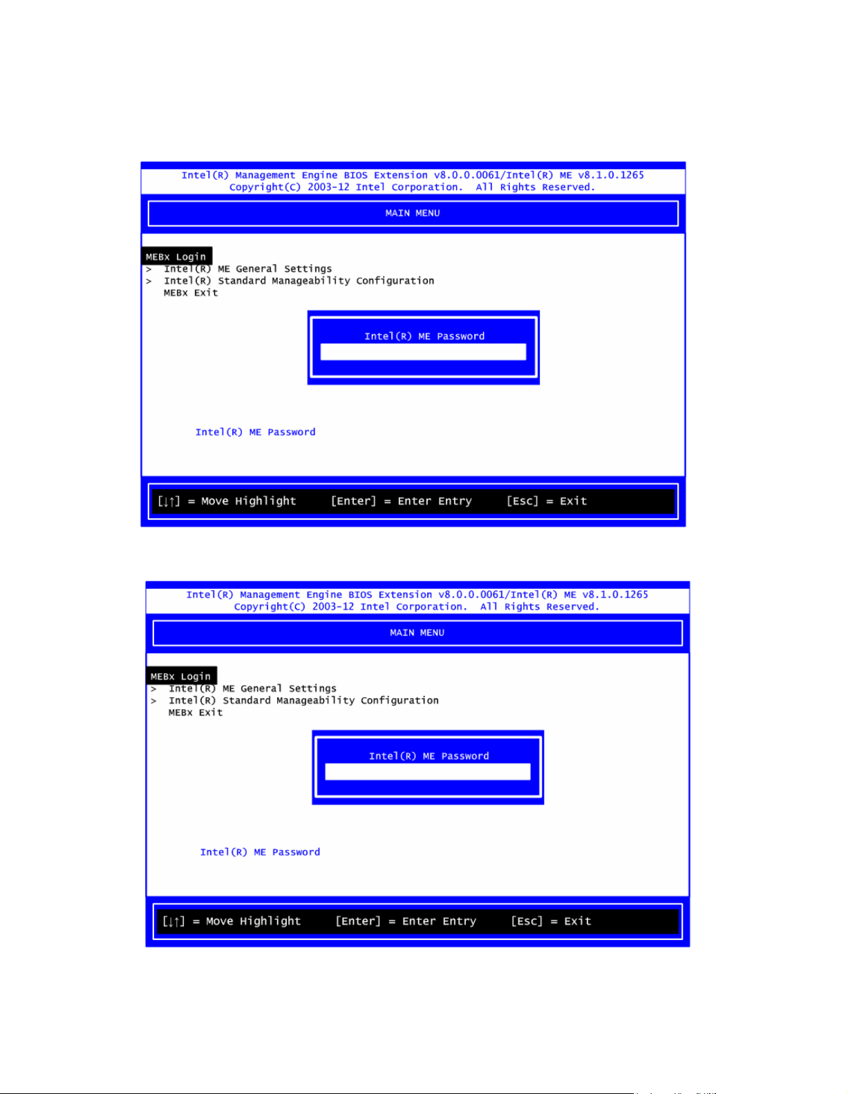
Set and Change Password
1. You will be ask ed to set a password when first log in. The default password is “admin”.
2. You will be ask ed to change the password before setting ME.
Page 59

3. You must confirm your new pass word while revising. The new password must contain:
(example: !!11qqQQ) (default value).
Eight characters
One upper case
One lower case
One number
One special symbol, such as ! 、 $ or ; , (、 " , excepted)
Underline ( _ ) and space are valid characters for password, but they won’t make higher
complexity.
iAMT Web Console
1. From a web browser, please type http://(IP ADDRESS):16992, which connects to
iAMT Web.
Example: http://10.1.40.214:16992
2. To log on, you will be requir ed to type in username and password for access to the Web.
USER: admin (default value)
PASS: (MEBx password)
Page 60
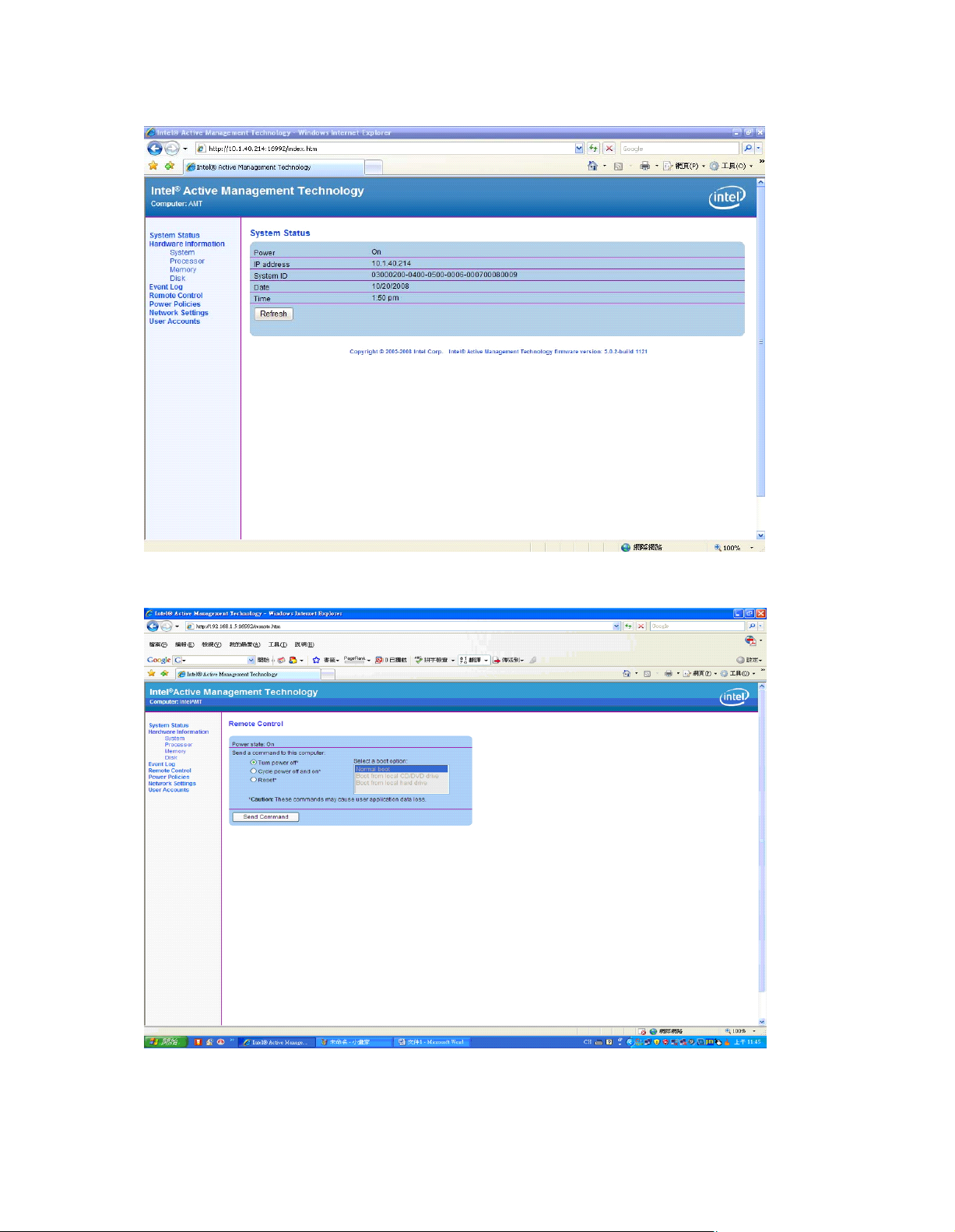
3. Enter the iAMT Web.
4. Click Remote Control, and select commands on the right side.
5. When you have finished using the iAMT Web console, close the Web browser.
 Loading...