

Page 1

661 Brea Canyon Rd., Suite 3
Walnut, CA 91789
tel: 909.598.7388, fax: 909.598.0218, www.acnodes.com
© Copyright 2009 Acnodes, Inc .
All right s reserved. Product descripti on and product specifi cations
are subjec t to c hange witho ut notic e. For latest produ ct informat ion ,
please visi t Acnodes’ web sit e at www.a cnod es.c om.
PC 8120
12-inch Core 2 Duo touch panel PC
1
Installation Guide
PC 8120: 12-inch Core 2 Duo touch panel PC
Page 2
© Copyright 2009 Acnodes, Inc .
All right s reserv ed. Prod uct descripti on and produ ct speci fi catio ns
are subjec t to c hange witho ut notic e. For latest produ ct informat ion ,
please visi t Acnodes’ web sit e at www.a cnod es.c om.
PC 5150
15-inch touch panel PC
661 Brea Canyon Rd., Suite 3
Walnut, CA 91789
tel: 909.598.7388, fax: 909.598.0218, www.acnodes.com
2
PC 8120
12-inch Core 2 Duo touch panel PC
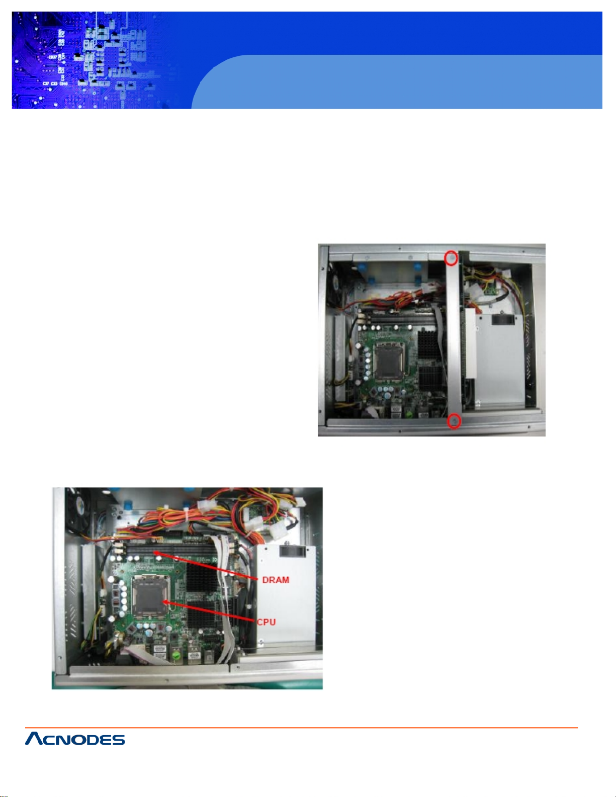
Installing the CPU and DRAM
The standard PC 8120 system is designed for Intel Core 2 Duo processors. The built-in CPU board provides two 240-
pin DDR2 DIMM sockets that support system memory up to 4GB.
Please refer to the instructions below illustrated with concise images, to upgrade the CPU, DRAM, PCI step by step:
Step 1: Unscrew screws to remove the rear chassis.
Step 2: Remove the riser card fix kit.
Step 3: Install the CPU and DDR DRAM in the PC
8120.
Page 3
661 Brea Canyon Rd., Suite 3
Walnut, CA 91789
tel: 909.598.7388, fax: 909.598.0218, www.acnodes.com
© Copyright 2009 Acnodes, Inc .
All right s reserved. Product descripti on and product specifi cations
are subjec t to c hange witho ut notic e. For latest produ ct informat ion ,
please visi t Acnodes’ web sit e at www.a cnod es.c om.
PC 8120
12-inch Core 2 Duo touch panel PC
3
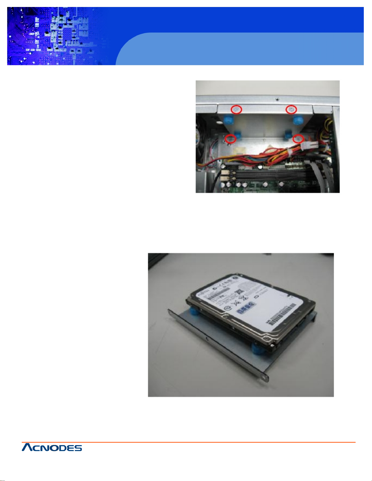
Installing the Hard Disk Drive
The PC 8120 offers a concenient drive bay module for users
to install HDD. The system offers users of one 2.5” Hard
Disk Drive for installation. Please follow the steps:
Step 1: Unscrew screws to remove the rear chassis.
Step 2: Remove the riser card fix kit.
Step 3: Unscrew 4 screws from the HDD drive bracket, and
take out HDD bracket kit to install 2.5” HDD.
Step 4: The installation is complete
Page 4
© Copyright 2009 Acnodes, Inc .
All right s reserv ed. Prod uct descripti on and produ ct speci fi catio ns
are subjec t to c hange witho ut notic e. For latest produ ct informat ion ,
please visi t Acnodes’ web sit e at www.a cnod es.c om.
PC 5150
15-inch touch panel PC
661 Brea Canyon Rd., Suite 3
Walnut, CA 91789
tel: 909.598.7388, fax: 909.598.0218, www.acnodes.com
4
PC 8120
12-inch Core 2 Duo touch panel PC
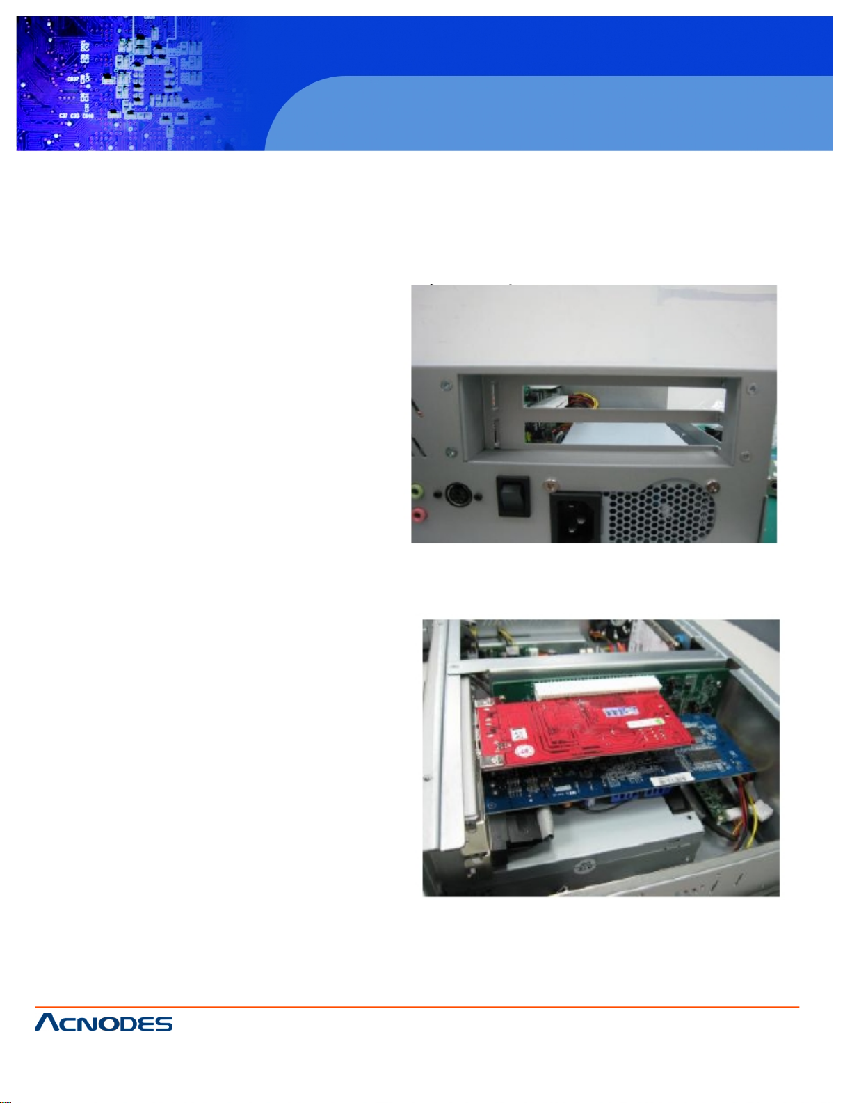
Add-on Card Installation
The PC 8120 provides a riser card for PCI slots
expansion. The riser card assemble can accomodate both
half-size expansion cards. To install the riser card, refer to
the following figure and instructions below:
Step 1: Remove the rear chassis.
Step 2: Remove the riser card fix kit.
Step 3: Remove plates.
Step 4: Insert the add-on card in the socket firmly
until it is completely sealed.
Page 5
661 Brea Canyon Rd., Suite 3
Walnut, CA 91789
tel: 909.598.7388, fax: 909.598.0218, www.acnodes.com
© Copyright 2009 Acnodes, Inc .
All right s reserved. Product descripti on and product specifi cations
are subjec t to c hange witho ut notic e. For latest produ ct informat ion ,
please visi t Acnodes’ web sit e at www.a cnod es.c om.
PC 8120
12-inch Core 2 Duo touch panel PC
5
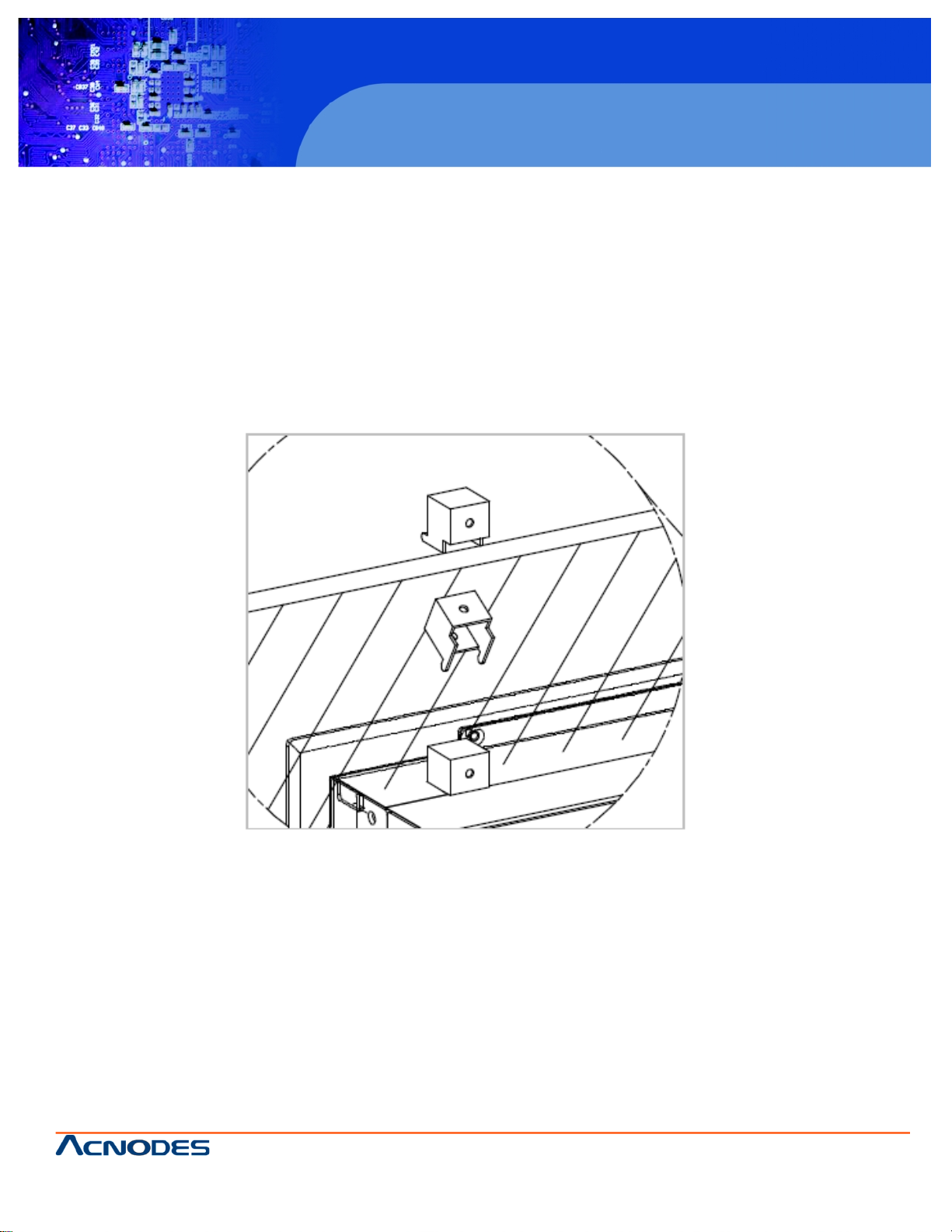
Mountings Ways -- Panel/Wall/Desktop
There are several mounting ways available for the PC 8120 system: Panel, Wall, and Desktop.
Panel Mounting
The PC 8120 is designed for panel mount application. To mount the PC 8120, the standard set of mounting kit (in-
cluded in the system packaging) is needed.
Page 6

© Copyright 2009 Acnodes, Inc .
All right s reserv ed. Prod uct descripti on and produ ct speci fi catio ns
are subjec t to c hange witho ut notic e. For latest produ ct informat ion ,
please visi t Acnodes’ web sit e at www.a cnod es.c om.
PC 5150
15-inch touch panel PC
661 Brea Canyon Rd., Suite 3
Walnut, CA 91789
tel: 909.598.7388, fax: 909.598.0218, www.acnodes.com
6
PC 8120
12-inch Core 2 Duo touch panel PC
ing figure.
Wall Mounting
The PC 8120 is designed for Wall mounting application. The wall mounting kit is optional. Please refer to the follow-
Step 1: Use six screws to fix the wall mounting bracket.
Step 2: Complete the wall mounting.
Page 7
661 Brea Canyon Rd., Suite 3
Walnut, CA 91789
tel: 909.598.7388, fax: 909.598.0218, www.acnodes.com
© Copyright 2009 Acnodes, Inc .
All right s reserved. Product descripti on and product specifi cations
are subjec t to c hange witho ut notic e. For latest produ ct informat ion ,
please visi t Acnodes’ web sit e at www.a cnod es.c om.
PC 8120
12-inch Core 2 Duo touch panel PC
7
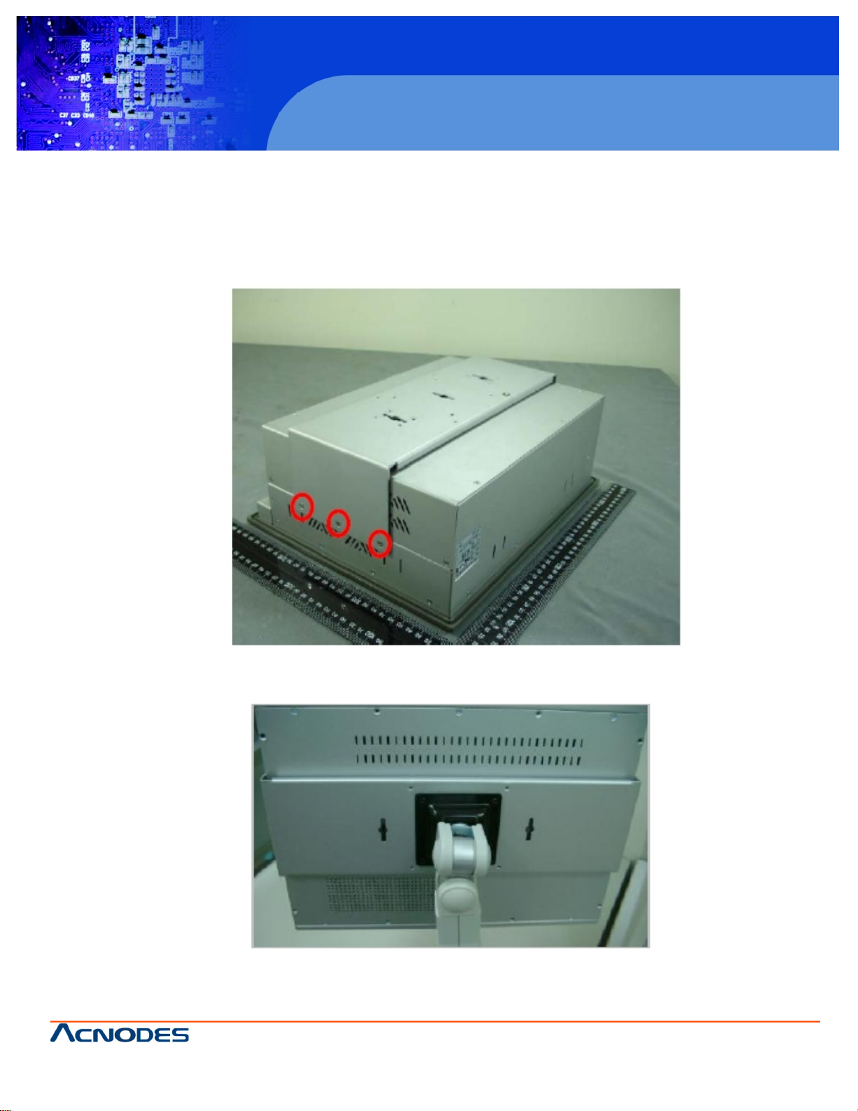
Desktop Mounting
The PC 8120 provides desktop mounting ways. It uses a wall bracket and a desktop stand. Please refer to the
following steps:
Step 1: Assemble the Wall mounting bracket
Step 2: Fix the desktop stand.
 Loading...