

Page 1

661 Brea Canyon Rd., Suite 3
Walnut, CA 91789
tel: 909.598.7388, fax: 909.598.0218, www.acnodes.com
© Copyright 2009 Acnodes, Inc .
All right s reserved. Product descripti on and product specifi cations
are subjec t to c hange witho ut notic e. For latest produ ct informat ion ,
please visi t Acnodes’ web sit e at www.a cnod es.c om.
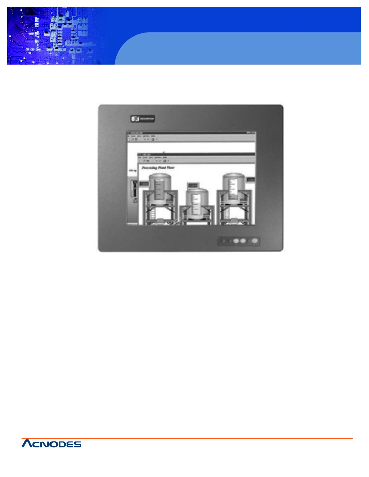
PC 8120
12-inch Core 2 Duo touch panel PC
1
User Manual
PC 8120: 12-inch Core 2 Duo touch panel PC
Page 2

© Copyright 2009 Acnodes, Inc .
All right s reserv ed. Prod uct descripti on and produ ct speci fi catio ns
are subjec t to c hange witho ut notic e. For latest produ ct informat ion ,
please visi t Acnodes’ web sit e at www.a cnod es.c om.
PC 5150
15-inch touch panel PC
661 Brea Canyon Rd., Suite 3
Walnut, CA 91789
tel: 909.598.7388, fax: 909.598.0218, www.acnodes.com
2
PC 8120
12-inch Core 2 Duo touch panel PC
Disclaimers
This manual has been carefully checked and believed to contain accurate information. Acnodes Corp. assumes no
responsibility for any infringements of patents or any third party’s rights, and any liability arising from such use.
Acnodes Corp. reserves the right to change or revise this document and/or product at any time without notice.
No part of this document may be reproduced, stored in retrieval system, or transmitted, in any form or by any means,
electronic, mechanical, photocopying, recording, or otherwose, without the prior written permission of Acnodes Corp.
Safety Precautions
Before getting started, please read the following importantly safety precautions.
1. The PC 8120 Series does not come equipped with an operating system. An operating system must be loaded first
before installing any software into the computer.
2. Be sure to groud yourself to prevent static charge when installing the internal components. Use a grouding wrist
strap and place all electronic components in any staticshielded devices. Most electronic components are sensitive to static
electrical change.
3. Disconnect the power cord from the PC 8120 Series before any installation. Be sure both the system and external
devices are turned OFF. A sudden surge of power could ruin sensitive components that the PC 8120 Series must be properly
grounded.
4. The brightness of the flat panel display will be getting weaker as a result of frequent usage. However, the operating
period varies depending on the application environment.
5. Turn OFF the system power before cleaning. Clean the system using a cloth only. Do not spray any liquid cleaner
directly onto the screen. The PC 8120 Series may come with or w/o a touchscreen. Although the touchscreen us chemical
resistant, it is recommended that you spray the liquid cleaner on a cloth first before qiping the screen. In case your system
comes without the touchscreen, you must follow the same procedure and not spray any cleaner on the flat panel directly.
6. Avoid using sharp objects to operate the touchscreen. Scratches on the touch screen may cause malfunction or
internail failure to the touchscreen.
7. The flat panel display is not susceptible to shock or vibration. When assembling the PC 8120, make sure it is
securely installed.
8. Do not open the system’s back cover. If opening the cover for maintenance is a must, only a trained technician is
allowed to do so. Integrated circuits on computer boards are sensitive to static electricity. To avoid damaging chips from
electrostatic discharge, observe the following precautions:
- Before handling a board or integrated circuit, touch an unpainted portion of the system unit chassis for a few seconds.
This will help to discharge any static electricity on your body.
- When handling boards and components, wear a wristgrounding strap, available from most electronic component
stores.
Page 3

661 Brea Canyon Rd., Suite 3
Walnut, CA 91789
tel: 909.598.7388, fax: 909.598.0218, www.acnodes.com
© Copyright 2009 Acnodes, Inc .
All right s reserved. Product descripti on and product specifi cations
are subjec t to c hange witho ut notic e. For latest produ ct informat ion ,
please visi t Acnodes’ web sit e at www.a cnod es.c om.
PC 8120
12-inch Core 2 Duo touch panel PC
3
Table of Contents
Disclaimers.............................................................................................................................2
Safety Approvals & Precations..................................................................................................2
Chapter 1 INTRODUCTION................................................................................................................5
1.1 General Description.................................................................................................................6
1.2 System Specifications.............................................................................................................6
1.2.1 Main CPU Board..........................................................................................................6
1.2.2 I/O System..................................................................................................................6
1.2.3 System Specification...................................................................................................6/7
1.3 Dimensions............................................................................................................................8
1.4 Front View and I/O Outlet.........................................................................................................9
1.4.1 Front View...................................................................................................................9
1.4.2 I/O Outlet....................................................................................................................10
1.5 Package List..........................................................................................................................11
CHAPTER 2 HARDWARE INSTALLATION...........................................................................................12
2.1 Installing CPU and DRAM........................................................................................................12
2.2 Installing Hard Disk Drive.........................................................................................................13
2.3 Add-on Card Installation...........................................................................................................15
2.4 Serial Port Interface.................................................................................................................16
2.5 DVI-I......................................................................................................................................16
2.6 Ethernet.................................................................................................................................17
2.7 Mounting Ways--Panel/Wall/Desktop........................................................................................18
2.7.1 Panel Mounting............................................................................................................18
2.7.2 Wall Mounting..............................................................................................................19
2.7.3 Desktop Mounting.........................................................................................................20
Chapter 3 PHOENIX-AWARD BIOS UTILITY........................................................................................21
3.1 Entering Setup.........................................................................................................................21
3.2 Control Keys............................................................................................................................21
3.3 Getting Help.............................................................................................................................22
3.4 The Main Menu.........................................................................................................................22
Page 4

© Copyright 2009 Acnodes, Inc .
All right s reserv ed. Prod uct descripti on and produ ct speci fi catio ns
are subjec t to c hange witho ut notic e. For latest produ ct informat ion ,
please visi t Acnodes’ web sit e at www.a cnod es.c om.
PC 5150
15-inch touch panel PC
661 Brea Canyon Rd., Suite 3
Walnut, CA 91789
tel: 909.598.7388, fax: 909.598.0218, www.acnodes.com
4
PC 8120
12-inch Core 2 Duo touch panel PC
3.5 Standard CMOS Setup Menu.....................................................................................................24
3.6 Advanced BIOS Feature............................................................................................................25
3.7 Advanced Chipset Feature.........................................................................................................29
3.8 Integrated Peripherals...............................................................................................................30
3.9 Power Management Setup.........................................................................................................33
3.10 PhP/PCI Configuration Setup.....................................................................................................37
3.11 PC Health Status......................................................................................................................39
3.12 Frequency Voltage Control.........................................................................................................40
3.13 Load Optimied Defaults..............................................................................................................41
3.14 Set Supervisor/User Password...................................................................................................42
3.15 Save & Exit Setup.....................................................................................................................43
3.16 Exit Without Saving...................................................................................................................44
CHAPTER 4 DRIVER INSTALLATION
4.1 System.................................................................................................................................45
4.2 Touch Screen.........................................................................................................................46
4.2.1 Specification................................................................................................................46
4.2.2 Driver Installation--Windows 200/XP/Vista.......................................................................47
4.2.3 Driver Installation--DOS.................................................................................................50
Page 5
661 Brea Canyon Rd., Suite 3
Walnut, CA 91789
tel: 909.598.7388, fax: 909.598.0218, www.acnodes.com
© Copyright 2009 Acnodes, Inc .
All right s reserved. Product descripti on and product specifi cations
are subjec t to c hange witho ut notic e. For latest produ ct informat ion ,
please visi t Acnodes’ web sit e at www.a cnod es.c om.
PC 8120
12-inch Core 2 Duo touch panel PC
5
Chapter 1: INTRODUCTION
This chapter contains general information and detailed specifications of
the PC 8120. Chapter 1 includes the following sections:
- General Description
- System Specification
- Dimensions
- Front View & I/O Outlets
- Package List
Page 6

© Copyright 2009 Acnodes, Inc .
All right s reserv ed. Prod uct descripti on and produ ct speci fi catio ns
are subjec t to c hange witho ut notic e. For latest produ ct informat ion ,
please visi t Acnodes’ web sit e at www.a cnod es.c om.
PC 5150
15-inch touch panel PC
661 Brea Canyon Rd., Suite 3
Walnut, CA 91789
tel: 909.598.7388, fax: 909.598.0218, www.acnodes.com
6
PC 8120
12-inch Core 2 Duo touch panel PC
1.1 General Description
The PC 8120 is a 12” Industrial panel PC which features Intel Core 2 Duo processor and Intel Q965 chipset to provide
powerful computing performance. This panel PC also offers the expansion ability with two PCI slots. It was WLAN module for
wireless connectivity. Further, the PC 8120 fits in with Aluminum compliant front bezel.
Powerful Computing: Intel Core 2 Duo Processor
The PC 8120 features Intel Core 2 Duo with a maximum of FSB 1066 MHz and Intel Q865+ICH8 chipset. It features
two 1394a ports, two gigabit Ethernet ports and up to 4GB of dual-channel DDR2 system memory which deliver high computing
capability for high performance-demanding applications.
Expandable for 2 PCI slots
The PC 8120 has two PCI slots for expansion purpose. User can easily plug in standard half-size PCI cards such as
motion card, communication card and so on.
WLAN antenna supported
The PC 8120 has optional WLAN module and antenna for wireless network connectivity.
This ideal industrial-grade panel computer PC 8120 can be applied to the serveral of industrial or commercial projects,
such as transportation, factory automation, HMI machine controller. Point of Sales, KIOSK and more. Moreover, PC 8120
provides highly reliable and highly flexible industrial-grade products in all-in-one solutions.
1.2 System Specifications
1.2.1. Main CPU Board
- CPU
- Socket LGA775 for Intel Core 2 Duo/Pentium Dual-Core/Celeron Processor with FSB 533/800/1066 MHz
- System Chipset
- BIOS
- Phoenix-Award BIOS, 16Mbit with RPL/PXE LAN Boot ROM, Smartview and Customer CMOS Backup
- System Memory
- Two 240-pin DDR2 DIMM maximum up to 4GB
- LZ Cache
- Integrated in CPU
- Bus Clock
- 533/800/1066 MHz
- Watchdog Timer
- Up to 255 levels as Reset feature
1.2.2. I/O System
- Standard I/O
- Three serial ports with power, two RS-232 and one RS-232/422/485
- One PS/2 for Keyboard and Mouse Interface
- Four USB Ports 2.0 compliant
- Two IEEE1394a Ports
- One DVI-I Output
Page 7

661 Brea Canyon Rd., Suite 3
Walnut, CA 91789
tel: 909.598.7388, fax: 909.598.0218, www.acnodes.com
© Copyright 2009 Acnodes, Inc .
All right s reserved. Product descripti on and product specifi cations
are subjec t to c hange witho ut notic e. For latest produ ct informat ion ,
please visi t Acnodes’ web sit e at www.a cnod es.c om.
PC 8120
12-inch Core 2 Duo touch panel PC
7
- Ethernet
- First port with i82566DM Gigabit Ethernet PHY, Second port with RTL8111B for Gigabit/Fast Ethernet
- Audio
- HD Audio for two channels output
- MIC-In, Line-Out
- Storage
- Four SATA-300 interface
-Box-Header
- One 26-pin for shared LPT
-Expansion Slot
- Two 32-bit PCI Master slots
1.2.3 System Specification
- 12” TFT LCD
- 5-wire Analog Resistive type Touchscreen
- Disk Drive Housing
-One internal 2.5” drive
- AC Power Supply
- Heat Dispensing Design
- Two slots for PCI expansion
- Net Weight
- 8 Kgs
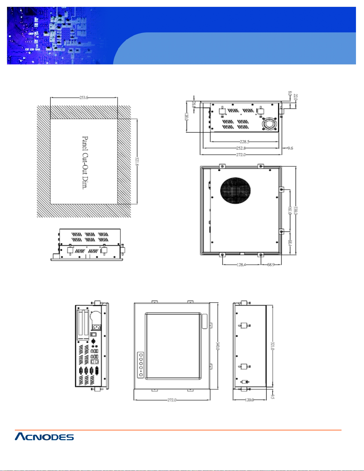
- DImension (Main Body Size)
- 340mm (16.51”)(W) x 120mm (9.14”)(D) x 272,, (13.19”)(H)
- Operating Temperature
- 0 degree C to 40 degree C; Relative humidity 50%
- Altitude
- 10,000 fft. (3,000 meters)
- Vibration (Operating)
- 5 to 500 Hz, 1 G random
- Shock (Operating)
- 10G peak acceleration (11 msec. duration)
Page 8
© Copyright 2009 Acnodes, Inc .
All right s reserv ed. Prod uct descripti on and produ ct speci fi catio ns
are subjec t to c hange witho ut notic e. For latest produ ct informat ion ,
please visi t Acnodes’ web sit e at www.a cnod es.c om.
PC 5150
15-inch touch panel PC
661 Brea Canyon Rd., Suite 3
Walnut, CA 91789
tel: 909.598.7388, fax: 909.598.0218, www.acnodes.com
8
PC 8120
12-inch Core 2 Duo touch panel PC
1.3 Dimension
Page 9
661 Brea Canyon Rd., Suite 3
Walnut, CA 91789
tel: 909.598.7388, fax: 909.598.0218, www.acnodes.com
© Copyright 2009 Acnodes, Inc .
All right s reserved. Product descripti on and product specifi cations
are subjec t to c hange witho ut notic e. For latest produ ct informat ion ,
please visi t Acnodes’ web sit e at www.a cnod es.c om.
PC 8120
12-inch Core 2 Duo touch panel PC
9
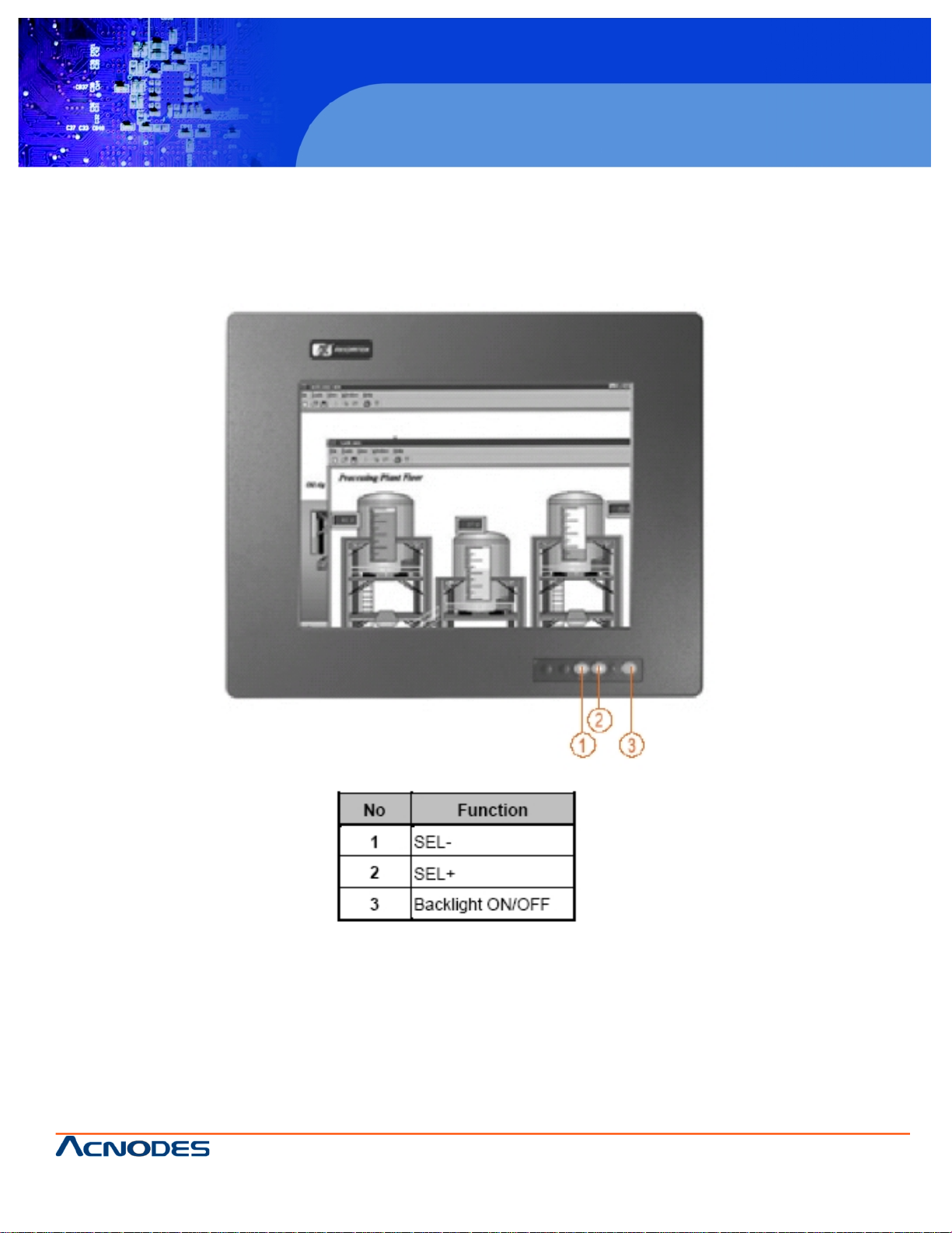
1.4 Front View and I/O Outlets
1.4.1. Front View
Please refer to the following illustration for features and controls of the PC 8120 front bezel.
Page 10
© Copyright 2009 Acnodes, Inc .
All right s reserv ed. Prod uct descripti on and produ ct speci fi catio ns
are subjec t to c hange witho ut notic e. For latest produ ct informat ion ,
please visi t Acnodes’ web sit e at www.a cnod es.c om.
PC 5150
15-inch touch panel PC
661 Brea Canyon Rd., Suite 3
Walnut, CA 91789
tel: 909.598.7388, fax: 909.598.0218, www.acnodes.com
10
PC 8120
12-inch Core 2 Duo touch panel PC
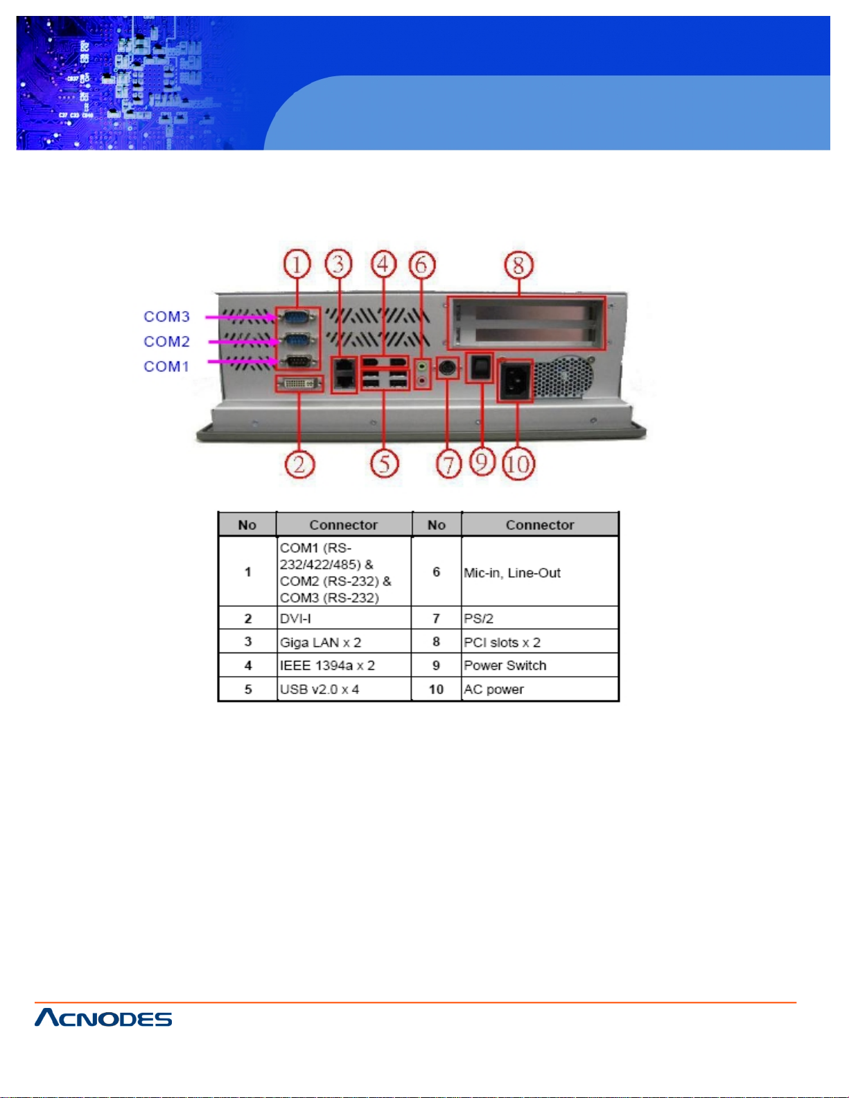
1.4.2 I/O Outlets
The following figure shows the I/O locations of the PC 8120.
Page 11

661 Brea Canyon Rd., Suite 3
Walnut, CA 91789
tel: 909.598.7388, fax: 909.598.0218, www.acnodes.com
© Copyright 2009 Acnodes, Inc .
All right s reserved. Product descripti on and product specifi cations
are subjec t to c hange witho ut notic e. For latest produ ct informat ion ,
please visi t Acnodes’ web sit e at www.a cnod es.c om.
PC 8120
12-inch Core 2 Duo touch panel PC
11
1.5 Package List
The package bundled with your PC 8120 should contain the following items:
- PC 8120 x 1
- AC power cord x 1
- Panel mount kit x 7
- Driver CD x 1
- LGA 775 CPU Cooler x 1
- DVI TO VGA Adapter x 1
- PS/2 Splitter - Y Cable x 1
- SATA Cable x 1
- VIA WLAN Kit x 1 (Optional)
- Wall Mount Bracket Kit x 1 (Optional)
- Desktop Kit x 1 (Optional)
*If you cannot find this package or any items are missing, please contact Acnodes Corp distributors immediately.
Page 12
© Copyright 2009 Acnodes, Inc .
All right s reserv ed. Prod uct descripti on and produ ct speci fi catio ns
are subjec t to c hange witho ut notic e. For latest produ ct informat ion ,
please visi t Acnodes’ web sit e at www.a cnod es.c om.
PC 5150
15-inch touch panel PC
661 Brea Canyon Rd., Suite 3
Walnut, CA 91789
tel: 909.598.7388, fax: 909.598.0218, www.acnodes.com
12
PC 8120
12-inch Core 2 Duo touch panel PC
Chapter 2: HARWARE INSTALLATION
The PC 8120 is convenient for your various hardware configurations in flexible ways, such as CPU (Central Processing
Unit), HDD (Hard Disk Drive), Memory Module (DRAM), CD-ROM, Add-On card, and more. The chapter 2 will show you how to
install the hardware. It includes:
- CPU
- DRAM
- Hard Disk
- Add-On Card
- Serial Port
- VGA
- Ethernet
- Mounting Ways
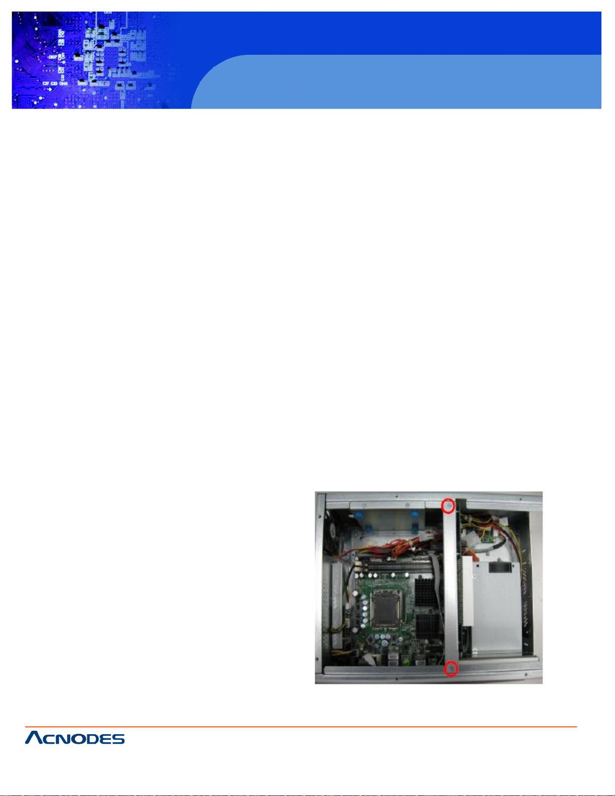
2.1 Installing the CPU and DRAM
The standard PC 8120 system is designed for Intel Core 2 Duo processors. The built-in CPU board provides two 240pin DDR2 DIMM sockets that support system memory up to 4GB.
Please refer to the instructions below illustrated with concise images, to upgrade the CPU, DRAM, PCI step by step:
Step 1: Unscrew screws to remove the rear chassis.
Step 2: Remove the riser card fix kit.
Page 13
661 Brea Canyon Rd., Suite 3
Walnut, CA 91789
tel: 909.598.7388, fax: 909.598.0218, www.acnodes.com
© Copyright 2009 Acnodes, Inc .
All right s reserved. Product descripti on and product specifi cations
are subjec t to c hange witho ut notic e. For latest produ ct informat ion ,
please visi t Acnodes’ web sit e at www.a cnod es.c om.
PC 8120
12-inch Core 2 Duo touch panel PC
13
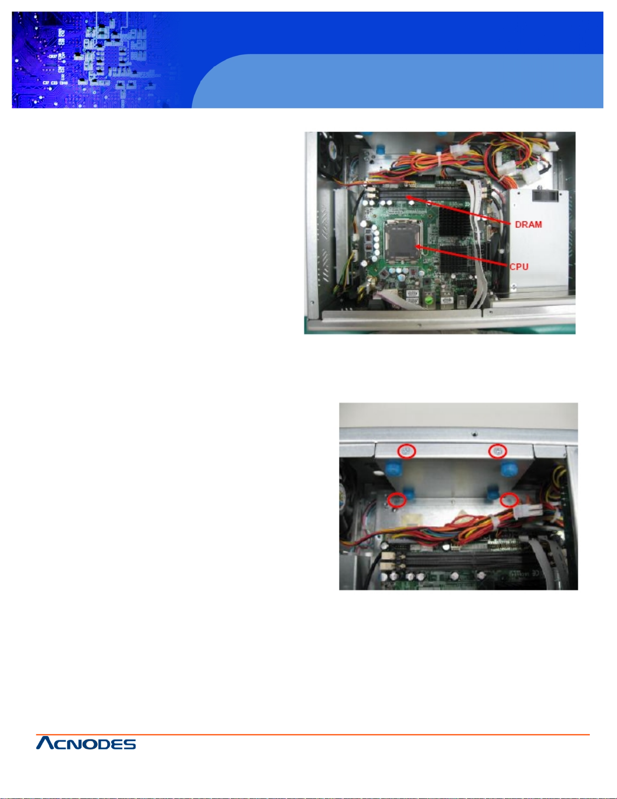
Step 3: Install the CPU and DDR DRAM in the PC 8120.
2.2 Installing the Hard Disk Drive
The PC 8120 offers a concenient drive bay module for users
to install HDD. The system offers users of one 2.5” Hard
Disk Drive for installation. Please follow the steps:
Step 1: Unscrew screws to remove the rear chassis.
Step 2: Remove the riser card fix kit.
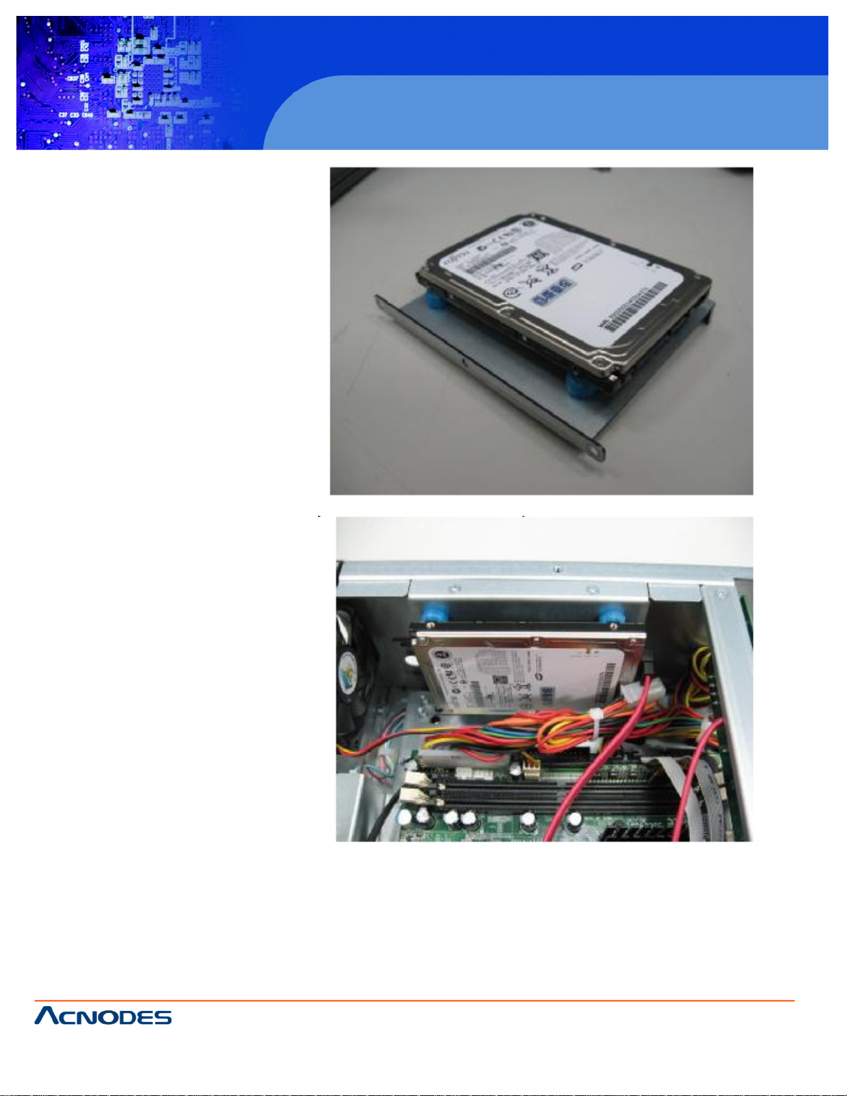
Step 3: Unscrew 4 screws from the HDD drive bracket, and
take out HDD bracket kit to install 2.5” HDD.
Page 14
© Copyright 2009 Acnodes, Inc .
All right s reserv ed. Prod uct descripti on and produ ct speci fi catio ns
are subjec t to c hange witho ut notic e. For latest produ ct informat ion ,
please visi t Acnodes’ web sit e at www.a cnod es.c om.
PC 5150
15-inch touch panel PC
661 Brea Canyon Rd., Suite 3
Walnut, CA 91789
tel: 909.598.7388, fax: 909.598.0218, www.acnodes.com
14
PC 8120
12-inch Core 2 Duo touch panel PC
Step 4: The installation is complete
Page 15
661 Brea Canyon Rd., Suite 3
Walnut, CA 91789
tel: 909.598.7388, fax: 909.598.0218, www.acnodes.com
© Copyright 2009 Acnodes, Inc .
All right s reserved. Product descripti on and product specifi cations
are subjec t to c hange witho ut notic e. For latest produ ct informat ion ,
please visi t Acnodes’ web sit e at www.a cnod es.c om.
PC 8120
12-inch Core 2 Duo touch panel PC
15
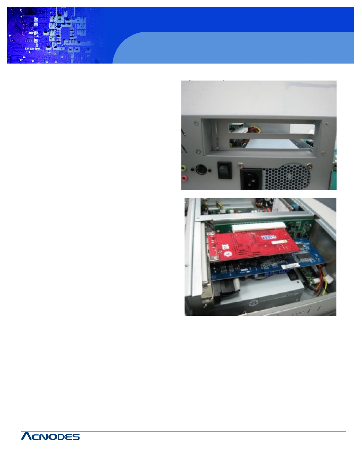
2.3 Add-on Card Installation
The PC 8120 provides a riser card for PCI slots
expansion. The riser card assemble can accomodate both
half-size expansion cards. To install the riser card, refer to
the following figure and instructions below:
Step 1: Remove the rear chassis.
Step 2: Remove the riser card fix kit.
Step 3: Remove plates.
Step 4: Insert the add-on card in the socket firmly
until it is completely sealed.
Page 16
© Copyright 2009 Acnodes, Inc .
All right s reserv ed. Prod uct descripti on and produ ct speci fi catio ns
are subjec t to c hange witho ut notic e. For latest produ ct informat ion ,
please visi t Acnodes’ web sit e at www.a cnod es.c om.
PC 5150
15-inch touch panel PC
661 Brea Canyon Rd., Suite 3
Walnut, CA 91789
tel: 909.598.7388, fax: 909.598.0218, www.acnodes.com
16
PC 8120
12-inch Core 2 Duo touch panel PC
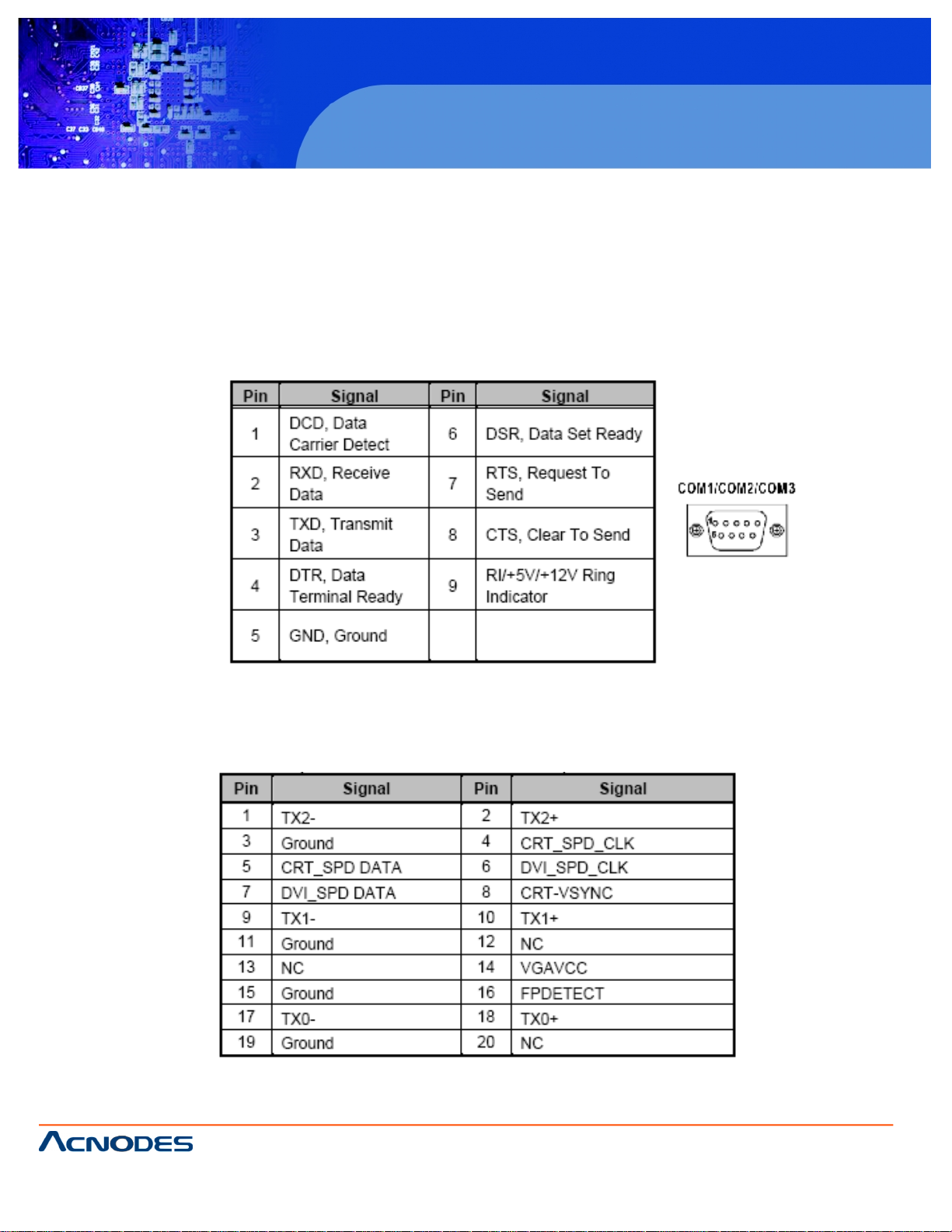
2.4 Serial Port Interface
The PC 8120 has three onboard serial ports. COM1, COM2, and COM3 are RS-232 Port Connector.
The connector, COM1, COM2, COM3 are DB-9 connector, and the following table shows the pin assignments of this
connector.
The PC 8120 has a DV-I interface connector. It is able to connect to an expansion CRT monitor, and the system can
display on both the flat pane and the CRT simultaneously.
Page 17

661 Brea Canyon Rd., Suite 3
Walnut, CA 91789
tel: 909.598.7388, fax: 909.598.0218, www.acnodes.com
© Copyright 2009 Acnodes, Inc .
All right s reserved. Product descripti on and product specifi cations
are subjec t to c hange witho ut notic e. For latest produ ct informat ion ,
please visi t Acnodes’ web sit e at www.a cnod es.c om.
PC 8120
12-inch Core 2 Duo touch panel PC
17
2.6 Ethernet
The PC 8120 provides a NE2000 compatible Ethernet (RJ-45) interfaces. For network connection, just plug in one
cable end of the system’s 10/100/1000-Base-T Hub into a standard RJ-45 connector. Refer to detailed pin assignment list
below.
Page 18

© Copyright 2009 Acnodes, Inc .
All right s reserv ed. Prod uct descripti on and produ ct speci fi catio ns
are subjec t to c hange witho ut notic e. For latest produ ct informat ion ,
please visi t Acnodes’ web sit e at www.a cnod es.c om.
PC 5150
15-inch touch panel PC
661 Brea Canyon Rd., Suite 3
Walnut, CA 91789
tel: 909.598.7388, fax: 909.598.0218, www.acnodes.com
18
PC 8120
12-inch Core 2 Duo touch panel PC
2.7 Mountings Ways -- Panel/Wall/Desktop
There are several mounting ways available for the PC 8120 system: Panel, Wall, and Desktop.
2.7.1 Panel Mounting
The PC 8120 is designed for panel mount application. To mount the PC 8120, the standard set of mounting kit (in-
cluded in the system packaging) is needed.
Page 19

661 Brea Canyon Rd., Suite 3
Walnut, CA 91789
tel: 909.598.7388, fax: 909.598.0218, www.acnodes.com
© Copyright 2009 Acnodes, Inc .
All right s reserved. Product descripti on and product specifi cations
are subjec t to c hange witho ut notic e. For latest produ ct informat ion ,
please visi t Acnodes’ web sit e at www.a cnod es.c om.
PC 8120
12-inch Core 2 Duo touch panel PC
19
ing figure.
2.7.2 Wall Mounting
The PC 8120 is designed for Wall mounting application. The wall mounting kit is optional. Please refer to the follow-
Step 1: Use six screws to fix the wall mounting bracket.
Step 2: Complete the wall mounting.
Page 20

© Copyright 2009 Acnodes, Inc .
All right s reserv ed. Prod uct descripti on and produ ct speci fi catio ns
are subjec t to c hange witho ut notic e. For latest produ ct informat ion ,
please visi t Acnodes’ web sit e at www.a cnod es.c om.
PC 5150
15-inch touch panel PC
661 Brea Canyon Rd., Suite 3
Walnut, CA 91789
tel: 909.598.7388, fax: 909.598.0218, www.acnodes.com
20
PC 8120
12-inch Core 2 Duo touch panel PC
2.7.3 Desktop Mounting
The PC 8120 provides desktop mounting ways. It uses a wall bracket and a desktop stand. Please refer to the
following steps:
Step 1: Assemble the Wall mounting bracket
Step 2: Fix the desktop stand.
Page 21

661 Brea Canyon Rd., Suite 3
Walnut, CA 91789
tel: 909.598.7388, fax: 909.598.0218, www.acnodes.com
© Copyright 2009 Acnodes, Inc .
All right s reserved. Product descripti on and product specifi cations
are subjec t to c hange witho ut notic e. For latest produ ct informat ion ,
please visi t Acnodes’ web sit e at www.a cnod es.c om.
PC 8120
12-inch Core 2 Duo touch panel PC
21
Chapter 3: PHOENIX-AWARD BIOS UTILITY
The Phoenix-Award BIOS provides users with a built-in Setup program to modify basic system configuration. All
configured parameters are sotred in a batter-backed-up RAM (CMOS RAM) to save the Setup information whenever the
power is turned off.
3.1 Entering Setup
There are two ways to enter the setup program. You may either turn ON the computer and press <Del> immediately, or press the <Del> and/or <Ctrl>, <Alt>, and <Esc> keys simltaneously when the following message appears at the
bottom of the screen during POST (Power on Self Test).
TO ENTER SETUP PRESS DEL KEY
If the message disappears before you respond and you still want to enter Setup, please restart the system to try it
again. Turning the system power OFF and ON, pressing the “RESET” button on the system case or simultaneously
pressing <Ctrl>, <Alt>, amd <Del> keys can restart the system. If you do not press kets at the right time and the system
doesn’t boot, an error message will pop out to prompt you the following information:
PRESS <F1> TO CONTINUE, <CRTL-ALT-ESC> OR <DEL> TO ENTER SETUP
3.2 Control Keys
Page 22

© Copyright 2009 Acnodes, Inc .
All right s reserv ed. Prod uct descripti on and produ ct speci fi catio ns
are subjec t to c hange witho ut notic e. For latest produ ct informat ion ,
please visi t Acnodes’ web sit e at www.a cnod es.c om.
PC 5150
15-inch touch panel PC
661 Brea Canyon Rd., Suite 3
Walnut, CA 91789
tel: 909.598.7388, fax: 909.598.0218, www.acnodes.com
22
PC 8120
12-inch Core 2 Duo touch panel PC
3.3 Getting Help
- Main Menu
The online description of the highlighted setup function is displayed at the bottom of the screen.
- Status Page Setup Menu/Option Page Setup Menu
Press <F1> to pop out a small Help window that provides the description of using appropriate keys and possible
selections for highlighted items. Press <F1> or <ESC> to exit the Help Window.
3.4 The Main Menu
Once you enter the Award BIOS CMOS Setup Utility, the Main Menu appears on the screen. in the Main Menu, there
are several Setup functions and a couple of Exit options for your selection. Use arrow keys to select the Setup page you
intend to configure then press <Enter> to accept or enter its sub-menu.
It is strongly recommended that you should avoid changing the chipset’s defaults. Both Award and your system manufacturer
have carefully set up these defaults that provide the best performance and reliability.
Page 23

661 Brea Canyon Rd., Suite 3
Walnut, CA 91789
tel: 909.598.7388, fax: 909.598.0218, www.acnodes.com
© Copyright 2009 Acnodes, Inc .
All right s reserved. Product descripti on and product specifi cations
are subjec t to c hange witho ut notic e. For latest produ ct informat ion ,
please visi t Acnodes’ web sit e at www.a cnod es.c om.
PC 8120
12-inch Core 2 Duo touch panel PC
23
3.5 Standard CMOS Setup Menu
The standard CMOS Setup Menu displays basic information about your system. use arrow keys to highlight each
item, and use <PgUp> or <PgDn> key to select the value you want in each item.
- Date
The date format is <day>, <date>, <month>, <year>. Press <F3> to show the calendar.
- Time
This item shows current time of your system with the format <hour> <minute> <second>. The time is calculated
based on the 24 military-time clock. For example, 1 P.M. is 13:00:00.
Page 24

© Copyright 2009 Acnodes, Inc .
All right s reserv ed. Prod uct descripti on and produ ct speci fi catio ns
are subjec t to c hange witho ut notic e. For latest produ ct informat ion ,
please visi t Acnodes’ web sit e at www.a cnod es.c om.
PC 5150
15-inch touch panel PC
661 Brea Canyon Rd., Suite 3
Walnut, CA 91789
tel: 909.598.7388, fax: 909.598.0218, www.acnodes.com
24
PC 8120
12-inch Core 2 Duo touch panel PC
- IDE Primary Master/Primary Slave
These items identify the types of each IDE channel installed in the computer. There are 45 predefined types (Sype 1 to
Type 45) and 2 user’s definable types. (Type User) for Enhanced IDE BIOS. Press <PgUp>/<+> or <PgDn>/<-> to selet a
numbered hard disk type or directly type the number and press <Enter>. Please be noted your drive’s specifications must
match the drive table. The hard disk will not work properly if you enter improper information. If your hard disk drive type does
not match or is not listed, you can use Type User to manually define your own drive type. If selecting Type use, you will be
asked to enter related information in the following items. Directly key in the information and press <Enter>. This information
should be provided in the documentation from your hard disk vendor or the system manufacturer.
If the HDD interface controller supports ESDI, select “Type 1”.
If the HDD interface controller supports SCSI, select “None”.
If the HDD interface controller supports CD-ROM, select “None.”
If there is no hard disk drive installed, select NONE and press <Enter>.
- Video
Select the display adapter type for your system.
- Halt On
This item determines whether the system will halt or not, if an error is detected while powering up.
Press <Esc> to return to the Main Menu page.
Page 25

661 Brea Canyon Rd., Suite 3
Walnut, CA 91789
tel: 909.598.7388, fax: 909.598.0218, www.acnodes.com
© Copyright 2009 Acnodes, Inc .
All right s reserved. Product descripti on and product specifi cations
are subjec t to c hange witho ut notic e. For latest produ ct informat ion ,
please visi t Acnodes’ web sit e at www.a cnod es.c om.
PC 8120
12-inch Core 2 Duo touch panel PC
25
3.6 Advanced BIOS Feautres
This section allows you to configure and imporve your system, to set up some system features according to your
preference.
- CPU Feature
Scroll to this item and press <Enter> to view the CPU Feature sub menu.
Page 26

© Copyright 2009 Acnodes, Inc .
All right s reserv ed. Prod uct descripti on and produ ct speci fi catio ns
are subjec t to c hange witho ut notic e. For latest produ ct informat ion ,
please visi t Acnodes’ web sit e at www.a cnod es.c om.
PC 5150
15-inch touch panel PC
661 Brea Canyon Rd., Suite 3
Walnut, CA 91789
tel: 909.598.7388, fax: 909.598.0218, www.acnodes.com
26
PC 8120
12-inch Core 2 Duo touch panel PC
- Hard Disk Boot Priority
Scroll to this item and press <Enter> to view the sub menu to decide the disk boot priority.
- Virus Warning
This option flashes on the screen. During and after the system boot up, any attempt to write to the boot sector or
partition table of the hard disk drive will hald the system with the following message. You can run an anti-virus program to
locate the problem. The default setting is “Disabled”.
- CPU L1 & L2 Cache
These two options speed up memory access. However, it depends on the CPU/chipset design. The fault setting is
“Enabled”. CPUs with no built-in internal cache will not provide the “CPU Internal Cache” iten on the menu.
Page 27

661 Brea Canyon Rd., Suite 3
Walnut, CA 91789
tel: 909.598.7388, fax: 909.598.0218, www.acnodes.com
© Copyright 2009 Acnodes, Inc .
All right s reserved. Product descripti on and product specifi cations
are subjec t to c hange witho ut notic e. For latest produ ct informat ion ,
please visi t Acnodes’ web sit e at www.a cnod es.c om.
PC 8120
12-inch Core 2 Duo touch panel PC
27
- Quick Power On Self Test
This option speeds up Power on Self Test (POST) after you turn on the system power. If set as Enabled, BIOS will
shorten or skip some check items during POST. The default setting is “Enabled”.
- First/Second/Third Boot Device
These items let you select the 1st, 2nd, and 3rd devices that the system will search for during its boot-up sequence.
The wide range of selection includes Floppy, LS120, ZIP100, HDD0~3, SCSI, and CDROM.
- Boot Other Device
This item allows the user to enable/disbable the boot device not listed on the First/Second/Third boot devices option
above. The defauly setting is “Enabled”.
- Boot up Floppy Seek
During POST, BIOS will determine the floppy disk drive type, 40 or 80 tracks. 360Kb type is 40 tracks while 720Kb,
1.2 MB and 1.44MB are all 80 tracks. The default value is “Enabled”.
- Boot Up NumLock Status
Set the Num Lock status when the system is powered on. The default value is “On”.
- Gate A20 Option
The default value is “Fast”.
- Typematic Rate Setting
This item determines the typematic rate of the keyboard. The default value is “Disabled”.
Page 28

© Copyright 2009 Acnodes, Inc .
All right s reserv ed. Prod uct descripti on and produ ct speci fi catio ns
are subjec t to c hange witho ut notic e. For latest produ ct informat ion ,
please visi t Acnodes’ web sit e at www.a cnod es.c om.
PC 5150
15-inch touch panel PC
661 Brea Canyon Rd., Suite 3
Walnut, CA 91789
tel: 909.598.7388, fax: 909.598.0218, www.acnodes.com
28
PC 8120
12-inch Core 2 Duo touch panel PC
- Typematic Rate (Chars/Sec)
This option refers to character numbers typed per second by the keyboard. The default calue is “6”.
- Typematic Delay (Msec)
This option defines how many milliseconds must elapse before a held-down key begins generating repeat characters.
The default value is “250”.
- Security Option
This item allows you to limit access to the system and Setup, or just to Setup. The defauly value is “Setup”.
- APIC Mode
Use this item to enable or disable APIC (Advanced Programmable Unterrupt Controller) made that porvides symmetric
multi-processing (SMP) for systems.
- MPS Version Control For OS
This item specifies the version of the Multiprocessor Specification (MPS). Version 1.4 has extended configuration
tables to improve support for multiple PCI bus configurations and provide future expandibility.
- Small Logo (EPA) Show
If enabled, the EPA logo will appear during system booting up; if disabled, the EPA logo will not appear.
Press <Esc> to return to the Main Menu page.
Page 29

661 Brea Canyon Rd., Suite 3
Walnut, CA 91789
tel: 909.598.7388, fax: 909.598.0218, www.acnodes.com
© Copyright 2009 Acnodes, Inc .
All right s reserved. Product descripti on and product specifi cations
are subjec t to c hange witho ut notic e. For latest produ ct informat ion ,
please visi t Acnodes’ web sit e at www.a cnod es.c om.
PC 8120
12-inch Core 2 Duo touch panel PC
29
3.7 Advanced Chipset Features
This section contains completely optimied chipset’s features on the board that you are strongly recommended to
leave all items on this page at their defauly values unless you are very familiar with the technical specifications of your system
hardware.
- System BIOS Cacheable
Selecting Enabled allows caching of the system BIOS ROM at F0000h-FFFFFh, resulting in better system performance. However, if any program writes to this memory area, a system errory may result. The default value is “Disabled”.
- Memory Hole At 15M-16M
You can reserve this area of system memory for ISA adapter ROM. When this area is reserved, it cannt be cached.
The user information of peripherals that need to use this area of system memory usually sidcusses their memory requirements.
- PCI Express Root Port Func
Scroll to this item and press <Enter> to view the sub menu to decide the PCI Express Port.
Press <Esc> to return to the Advanced Chipset Features page.
**VGA Setting**
- PEG/Onchip VGA Control
Use this item to choose the primary display card.
- On-Chip Frame Buffer Size
Use this item to set the VGA frame buffer size.
- DVMT Mode
DVMT (Dynamic Video Memory Technology) helps you select the video mode.
- DVMT.Fixed Memory Size
DVMT (Dynamic Video Memory Technology) allows you to select a maximum size of dynamic amount of usage of the
video memory. The system would configure the video memory dependent on your application.
- Boot Display
This item is for Intel define ADD card only.
Press <Esc> to return to the Main Menu page.
Page 30

© Copyright 2009 Acnodes, Inc .
All right s reserv ed. Prod uct descripti on and produ ct speci fi catio ns
are subjec t to c hange witho ut notic e. For latest produ ct informat ion ,
please visi t Acnodes’ web sit e at www.a cnod es.c om.
PC 5150
15-inch touch panel PC
661 Brea Canyon Rd., Suite 3
Walnut, CA 91789
tel: 909.598.7388, fax: 909.598.0218, www.acnodes.com
30
PC 8120
12-inch Core 2 Duo touch panel PC
3.8 Integrated Peripherals
This section allows you to configure your SuperIO Device, IDE Function and Onboard Device.
- OnChip IDE Device
Scroll to this item and press <Enter> to view the sub menu OnChip IDE Device.
- IDE HDD Block Mode
Block mode is also called block transfer, multiple commands, or multiple sectore read/write. If your IDE hard drive
supports block mode (most new drives do), select Enabled for automatic detection of the optimal number of block read/writes
persector the drive van support.
- IDE DMA transfer access
Automatic data transfer between system memory and IDE device with minumum CPU intervention. This improves data
throughout and frees CPU to perform other tasks.
- On-Chip Primary/Secondary PC IDE
The integrated peripheral controller contains an IDE interface with support for two IDE channels. Select Enabled to
activate each channel sperately. The default calue is “Enabled.”
- IDE Master/Slave PIO
The four IDE PIO (Programmed Input/Output) fields let you set PIO mode (0-4) for each of the four IDE devices that the
onboard IDE interface supports. Modes 0 to 4 provide successiveely increased performance. In Auto mode, the system
automatically determines the best mode for each device.
- IDE Master/Slave USMA
Select the mode of operation for the IDE drive. Ultra DMA-33/66/100/133 implementation is possible only if your IDE
hard drive supports it and the operating environment includes a DMA driver. If your hard drive and your system software both
support Ultra DMA-33/66/100/133, select Auto to enable UDMA mode by BIOS.
- SATA Mode
There are these options for you to set up SATAmode: IDE, RAID, or AHCI.
Page 31

661 Brea Canyon Rd., Suite 3
Walnut, CA 91789
tel: 909.598.7388, fax: 909.598.0218, www.acnodes.com
© Copyright 2009 Acnodes, Inc .
All right s reserved. Product descripti on and product specifi cations
are subjec t to c hange witho ut notic e. For latest produ ct informat ion ,
please visi t Acnodes’ web sit e at www.a cnod es.c om.
PC 8120
12-inch Core 2 Duo touch panel PC
31
- LEGACY Mode Support
Legacy mode support allows devices to function in an operating environment that is not USB-aware.
Press <Esc> to return to the Integrated Peripheral’s page.
- Super IO Device
Scroll to this item and press <Enter> to view the sub menu Super IO Device
- Onboard FDC Controller
Select Enabled if your system has a floppy disk controller (FDC) installed on the system board and you wish to use
it. If you install and-in FDC or the system has no floppy drive, select Disabled in this field. The options available are Enabled,
Disabled.
- Onboard Serial Port 1/2/3/4
Select an address and corresponding interrupt for the serial port. Options: 3F8/IRQ3, 3E8/IRQ3, 3E8/IRQ4, 2F8/
IRQ3, Disabled Auto.
Serial Port 1/2/3/4 Use IRQ
These items assign which I/O address to access onboard serial port 1/2/3/4.
- Onboard Parallel Port
This item allows you to determine access onboard parallel port controller with which I/O address. The options
available are 378H/IRQ5, 278H/IRQ5, 3BC/IRQ7, Disabled. The 3BC option does not support any EPP modes.
Page 32

© Copyright 2009 Acnodes, Inc .
All right s reserv ed. Prod uct descripti on and produ ct speci fi catio ns
are subjec t to c hange witho ut notic e. For latest produ ct informat ion ,
please visi t Acnodes’ web sit e at www.a cnod es.c om.
PC 5150
15-inch touch panel PC
661 Brea Canyon Rd., Suite 3
Walnut, CA 91789
tel: 909.598.7388, fax: 909.598.0218, www.acnodes.com
32
PC 8120
12-inch Core 2 Duo touch panel PC
- Parallel Port Mode
Select an operating mode for the onboard parallel (printer) port. Select Normal unless your hardware and software
require one of the other modes offered in this field. The options available are EPP1.9, ECP, SPP, ECPEPP1.7, EPP1.7.
- ECP Mode Use DMA
Select a DMA channel for the parallel port for use during ECP mode.
- PWRON After PWR-Fail
This item enables your computer to automatically restart or return to its operating status.
Press <Esc> to return to the integrated peripherals page.
- Onboard Lan1/Lan2 Boot ROM
Use this item to enable or disable the Boot ROM function of the onboard LAN1/LAN2 chips when the system boots up.
- USB Device Setting
Scroll to this item and press <Enter> to view the sub menu USB Device Setting. ISB (CN16) is not working when
USB1.0 Controller is disabled.
Press <Esc> twice to return to the Main Menu.
Page 33

661 Brea Canyon Rd., Suite 3
Walnut, CA 91789
tel: 909.598.7388, fax: 909.598.0218, www.acnodes.com
© Copyright 2009 Acnodes, Inc .
All right s reserved. Product descripti on and product specifi cations
are subjec t to c hange witho ut notic e. For latest produ ct informat ion ,
please visi t Acnodes’ web sit e at www.a cnod es.c om.
PC 8120
12-inch Core 2 Duo touch panel PC
33
3.9 Power Management Setup
The Power Management Setup allows you to save energy of your system effectively. It will shut down the hard disk
and turn OFF video display after a period of inactivity.
Page 34

© Copyright 2009 Acnodes, Inc .
All right s reserv ed. Prod uct descripti on and produ ct speci fi catio ns
are subjec t to c hange witho ut notic e. For latest produ ct informat ion ,
please visi t Acnodes’ web sit e at www.a cnod es.c om.
PC 5150
15-inch touch panel PC
661 Brea Canyon Rd., Suite 3
Walnut, CA 91789
tel: 909.598.7388, fax: 909.598.0218, www.acnodes.com
34
PC 8120
12-inch Core 2 Duo touch panel PC
- ACPI Function
This item allows you to enable/disable the Advanced Configuration and Power Management (ACPI). The function is
always “Enabled”.
- ACPI Suspend Type
This item specifies the power saving modes for ACPI function. If your operating system supports ACPI, such as
Windows 98SE, Windows ME, and Windows 2000, you can choose to enter the Standby mode in S1 (POS) or S3 (CPU or
chipset) and hardware maintains all system context.
[S1(POS)] The S1 sleep mode is a low power state. In this state, no system context is lost. (CPU or chipset) and
hardware maintains all system context.
[S3(STR) The S3 sleep mode is a lower power state where the information of system configuration and open applications/files is saved to main memory that remains powered while most other hardware components turn off to save energy. The
information sotred in memory will be used to restore the system when a “wake up” event occurs.
- Run VGABIOS is S3 Resume
When this item is set Auto, the system will run VGA BIOS if it is reaurned from the S3 state.
- Power Management
This option allows you to select the type (or degree) of power saving for Doze, Standby, and Suspend modes. The
table below describes each power management mode:
Page 35

661 Brea Canyon Rd., Suite 3
Walnut, CA 91789
tel: 909.598.7388, fax: 909.598.0218, www.acnodes.com
© Copyright 2009 Acnodes, Inc .
All right s reserved. Product descripti on and product specifi cations
are subjec t to c hange witho ut notic e. For latest produ ct informat ion ,
please visi t Acnodes’ web sit e at www.a cnod es.c om.
PC 8120
12-inch Core 2 Duo touch panel PC
35
-Video Off Method
This setting determines the manner in which the monitor is blanked.
- Vide Off in Suspend
This item defines if the video is powered down when the system is put into suspend mode.
- Suspend Type
If this item is set to the default Stop Grant, the CPU will go into Idle Mode during power saving mode.
- Modern Use IRQ
If you want an incoming call on a modem to automatically resume the system from a powersaving mdoe, use this
item to specify the interrupt request line (IRQ) used by the modem. You might have to connect the fax/modem to the board
Wake On Modern connector for working this feature.
-Suspend Mode
After the selected period of system inactivity (i minute to 1 hour), all devices except the CPU shut off. The defauly
value is “Disabled”.
Page 36

© Copyright 2009 Acnodes, Inc .
All right s reserv ed. Prod uct descripti on and produ ct speci fi catio ns
are subjec t to c hange witho ut notic e. For latest produ ct informat ion ,
please visi t Acnodes’ web sit e at www.a cnod es.c om.
PC 5150
15-inch touch panel PC
661 Brea Canyon Rd., Suite 3
Walnut, CA 91789
tel: 909.598.7388, fax: 909.598.0218, www.acnodes.com
36
PC 8120
12-inch Core 2 Duo touch panel PC
- HDD Power Down
If HDD activity is not detected for the length of time specified in this field, the hard disk drive will be powered down while
all other devices remain active.
- Sort-Off by PWR-BTTN
This option only works with systems using an ATX power supply. It also allows the user to define which type of soft
power OFF sequence the system will follow. The default value is “Instant-Off.”
- Wake-Up by PCI card
If endable this item, the system can automatically resume when the PCI Modem or PCI LAN card receives an incoming
call.
- Power on by Ring
This option allows the system to resume or wake up upon detecting any ring signals coming from an installed modem.
The default value is “Enabled”.
- Resume by Alarm
If enable this item, the system can automatically resume after a fixed time in accordance with the system’s RTC
(realtime clock).
**Reload Global Timer Events**
Global Timer (power management) events can prevent the system from entering a power saving mode or can awaken
the system from such a mode.
- Primary/Secondary IDE 0/1
Use this item to configure the IDE devices monitored by the system.
- FDD, COM, LPT Port
Use this item to configure the IDE devices monitored by the system.
- PCI PIRQ (A-D)#
This item can be used to detect PCI device activities; if no activity, the system will eneter the sleep mode.
Press <Esc> to return to the Main Menu page.
Page 37

661 Brea Canyon Rd., Suite 3
Walnut, CA 91789
tel: 909.598.7388, fax: 909.598.0218, www.acnodes.com
© Copyright 2009 Acnodes, Inc .
All right s reserved. Product descripti on and product specifi cations
are subjec t to c hange witho ut notic e. For latest produ ct informat ion ,
please visi t Acnodes’ web sit e at www.a cnod es.c om.
PC 8120
12-inch Core 2 Duo touch panel PC
37
3.10 PnP/PCI Configuration Setup
This section describes configuring the PCi bus system. PCI, or Personal Computer Interconnect, is a system which
allows I/O devices to operate at speeds nearing the speed the CPU itself uses when communicating with its own special
components. This section covers some very technical items and it is strongly recommended that only experienced users
should make any changes to the default settings.
- Reset Configuration Data
Normally, you leave this item Disabled. Select Enabled to reset Extended System Configuration Data (ESCD) when
you exit Setup or if installing a new add-on cause the system reconfiguration a serious conflict that the operating system can
not boot. Options: Enabled, Disabled.
- Resources Controlled By
The Award Plug and Play BIOS can automatically configure all boot and Plug and Play-compatible devices. If you
select Auto, all interrupt request (IRQ), DMA assignment, and used DMA fields disapper, as the BIOS automatically assigns
thm. The default value is “Manual”.
- IRQ Resources
When resources are controlled manually, assign each system interrupt to one of the following types in accordance
with the type of devices using the interrupt:
1. Legacy ISA Devices compliant with the original PC AT bus specification, requiring a specific interrupt (such as IRQ4
for serial port 1).
2. PCI/ISA PnP Devices compliaant with the Plug and Play standard, whethere designed for PCI or ISA bus
architechture.
Page 38

© Copyright 2009 Acnodes, Inc .
All right s reserv ed. Prod uct descripti on and produ ct speci fi catio ns
are subjec t to c hange witho ut notic e. For latest produ ct informat ion ,
please visi t Acnodes’ web sit e at www.a cnod es.c om.
PC 5150
15-inch touch panel PC
661 Brea Canyon Rd., Suite 3
Walnut, CA 91789
tel: 909.598.7388, fax: 909.598.0218, www.acnodes.com
38
PC 8120
12-inch Core 2 Duo touch panel PC
The default value is “PCI/ISA PnP”.
- PCI/VGA Palette Snoop
Some non-standard VGA display cards may not show colors properly. This item allows you to set whether MPEG ISA/
VESA VGA cards can work with PCI/VGA or not. When enabled, a PCI/VGA can work with a MPEG ISA/VESA VGA card;
when disabled, a PCI/VGA cannot work with a MPEG ISA/VESA Card.
**PCI Express relative Items**
- Maximum Payload Size
When using DDR SDRAM and buffer size selection, another consideration in designing a payload memory is the size
of the buffer for data sotrage. Maximum Payload Size defines the maximum TLP (Transaction Layer Packet) data payload size
for the device.
Press <esc> to return to the Main Menu page.
Page 39

661 Brea Canyon Rd., Suite 3
Walnut, CA 91789
tel: 909.598.7388, fax: 909.598.0218, www.acnodes.com
© Copyright 2009 Acnodes, Inc .
All right s reserved. Product descripti on and product specifi cations
are subjec t to c hange witho ut notic e. For latest produ ct informat ion ,
please visi t Acnodes’ web sit e at www.a cnod es.c om.
PC 8120
12-inch Core 2 Duo touch panel PC
39
3.11 PC Health Status
This section supports hardware monitoring that lets you monitor those parameters for critical voltages, tempera-
tures and fan speed of the board.
- Shutdown Temperature
It helps you set the maximum temperature the system can reach before powering down.
- Current SYSTEM Temperature
Show you the current system temperature.
- Current CPU Temperature
These read-only fields show the functions of the hardware thermal sensor by CPU thermal diode that monitors the
chip blocks to ensure a stable system,
- Vcore +3.3V/+5V/+12V/VBAT(V)/5VSB
Press <Esc> to return to the Main Menu page.
Page 40

© Copyright 2009 Acnodes, Inc .
All right s reserv ed. Prod uct descripti on and produ ct speci fi catio ns
are subjec t to c hange witho ut notic e. For latest produ ct informat ion ,
please visi t Acnodes’ web sit e at www.a cnod es.c om.
PC 5150
15-inch touch panel PC
661 Brea Canyon Rd., Suite 3
Walnut, CA 91789
tel: 909.598.7388, fax: 909.598.0218, www.acnodes.com
40
PC 8120
12-inch Core 2 Duo touch panel PC
3.12 Frequency/Voltage Control
This section is to control the CPU frequency and Supply Voltage. DIMM OverVOltage and AGP voltage.
- CPU Clock Ratio
Use this item to select the CPU’s frequency
- Auto Detect PCI Clk
The eneabled item can automatically disable the clock source for a PCI slot without a module, to reduce EMI
(ElectroMagnetic Interference).
- Spread Spectrum
If spectrum is enabled, EMI (ElectroMagnetic Interference) generated by the system can be significantly reduced.
Press <Esc> to return to the Main Menu page.
Page 41

661 Brea Canyon Rd., Suite 3
Walnut, CA 91789
tel: 909.598.7388, fax: 909.598.0218, www.acnodes.com
© Copyright 2009 Acnodes, Inc .
All right s reserved. Product descripti on and product specifi cations
are subjec t to c hange witho ut notic e. For latest produ ct informat ion ,
please visi t Acnodes’ web sit e at www.a cnod es.c om.
PC 8120
12-inch Core 2 Duo touch panel PC
41
3.13 Load Optimized Defaults
This option allows you to load the default values to your system configuration. These default settings are optimal
and enable all high performance features.
To load SETUP defaults value to CMOS SRAM, enter “Y”. If not, enter “N.”
Page 42

© Copyright 2009 Acnodes, Inc .
All right s reserv ed. Prod uct descripti on and produ ct speci fi catio ns
are subjec t to c hange witho ut notic e. For latest produ ct informat ion ,
please visi t Acnodes’ web sit e at www.a cnod es.c om.
PC 5150
15-inch touch panel PC
661 Brea Canyon Rd., Suite 3
Walnut, CA 91789
tel: 909.598.7388, fax: 909.598.0218, www.acnodes.com
42
PC 8120
12-inch Core 2 Duo touch panel PC
3.14 Set Supervisor/Used Passoword
You can set either supervisor or user password, or both of them. The differences are:
1. Supervisor password: can eneter and change the options of the setup menus.
2. User password: just can eneter but do not have the right to change the options of the setup menus.
When you select this function, the following message will appear at the center of the screen to assist you in creating a
password.
Enter Password:
Type the password with eight characters at most, and press <enter>. The password typed will now clear any previously enetered password from CMOS memory. You will be asked to confirm the password. Type the password again and press
<Enter>. You may also press <Esc> to abort the selection and not enter a password.
To disable password, just press <Enter> when you are prompted to eneter password. A message will confirm the
password being disabled. Once the password is disabled, the system will boot and you can eneter Setup freely.
Password Disabled:
When a password is enabled, you have to type it every time you enter Setup. This prevents any unauthorized person
from changing your system configuration.
Additionall when a password is enabled, you can also require the BIOS to request a password every time the system
reboots. This would prevent: unauthorized use of your computer.
Page 43

661 Brea Canyon Rd., Suite 3
Walnut, CA 91789
tel: 909.598.7388, fax: 909.598.0218, www.acnodes.com
© Copyright 2009 Acnodes, Inc .
All right s reserved. Product descripti on and product specifi cations
are subjec t to c hange witho ut notic e. For latest produ ct informat ion ,
please visi t Acnodes’ web sit e at www.a cnod es.c om.
PC 8120
12-inch Core 2 Duo touch panel PC
43
3.15 Save & Exit Setup
This allows you to determine whether or not to accept the modifications. Type “Y” quits the setup utility and saves
all changes into the CMOS memory. Typing “N” brigs you back to Setup utility.
Page 44

© Copyright 2009 Acnodes, Inc .
All right s reserv ed. Prod uct descripti on and produ ct speci fi catio ns
are subjec t to c hange witho ut notic e. For latest produ ct informat ion ,
please visi t Acnodes’ web sit e at www.a cnod es.c om.
PC 5150
15-inch touch panel PC
661 Brea Canyon Rd., Suite 3
Walnut, CA 91789
tel: 909.598.7388, fax: 909.598.0218, www.acnodes.com
44
PC 8120
12-inch Core 2 Duo touch panel PC
3.16 Exit Without Saving
Select this option to exit the Setup utility without saving the changes you have made in this session. Typing “Y” will
quit the Setup utility without saving the modifications. Typing “N” will return you to Setup utility.
Page 45

661 Brea Canyon Rd., Suite 3
Walnut, CA 91789
tel: 909.598.7388, fax: 909.598.0218, www.acnodes.com
© Copyright 2009 Acnodes, Inc .
All right s reserved. Product descripti on and product specifi cations
are subjec t to c hange witho ut notic e. For latest produ ct informat ion ,
please visi t Acnodes’ web sit e at www.a cnod es.c om.
PC 8120
12-inch Core 2 Duo touch panel PC
45
4.1 System
PC 8120 supports Windows 2000/XP/Vista. To facilitate the installation of the system driver, please carefully read the
instructions in this chapter before start installing.
1. Here is the path for the system driver:
Panel series\PC8120\Driver
2. Select all files, following the installing procedure, and finally press OK.
Page 46

© Copyright 2009 Acnodes, Inc .
All right s reserv ed. Prod uct descripti on and produ ct speci fi catio ns
are subjec t to c hange witho ut notic e. For latest produ ct informat ion ,
please visi t Acnodes’ web sit e at www.a cnod es.c om.
PC 5150
15-inch touch panel PC
661 Brea Canyon Rd., Suite 3
Walnut, CA 91789
tel: 909.598.7388, fax: 909.598.0218, www.acnodes.com
46
PC 8120
12-inch Core 2 Duo touch panel PC
4.2 Touch Screen
4.2.1 Specification
Page 47

661 Brea Canyon Rd., Suite 3
Walnut, CA 91789
tel: 909.598.7388, fax: 909.598.0218, www.acnodes.com
© Copyright 2009 Acnodes, Inc .
All right s reserved. Product descripti on and product specifi cations
are subjec t to c hange witho ut notic e. For latest produ ct informat ion ,
please visi t Acnodes’ web sit e at www.a cnod es.c om.
PC 8120
12-inch Core 2 Duo touch panel PC
47
4.2.2 Driver Installation - Windows 2000/XP/Vista
The PC 8120 provides a driver of the touch screen that users can install it under operating system Windown 2000/
XP/Vista. To facilitate this touch screen driver installation, users should read the instructions in this chapter carefully before
start the installation.
1. Insert Driver CD and follow the path to select the “Panel series\PC8120\Driver\Step5 -
Touch\Driver\Windows2000_CP_Vista Universal Driver\Setup.exe”.
2. Follow the installing procedure and press OK.
3. Click Start menu and select “PenMount Utilities”, and then a “PenMount Control panel” pops out.
Page 48

© Copyright 2009 Acnodes, Inc .
All right s reserv ed. Prod uct descripti on and produ ct speci fi catio ns
are subjec t to c hange witho ut notic e. For latest produ ct informat ion ,
please visi t Acnodes’ web sit e at www.a cnod es.c om.
PC 5150
15-inch touch panel PC
661 Brea Canyon Rd., Suite 3
Walnut, CA 91789
tel: 909.598.7388, fax: 909.598.0218, www.acnodes.com
48
PC 8120
12-inch Core 2 Duo touch panel PC
4. Select the “Standard Calibrate” tab.
5. Calibration
To adujust the display with touch panel, click “Calibration” and follow the calibrate point to do calibration; there are five
points on screen for calibration.
Page 49

661 Brea Canyon Rd., Suite 3
Walnut, CA 91789
tel: 909.598.7388, fax: 909.598.0218, www.acnodes.com
© Copyright 2009 Acnodes, Inc .
All right s reserved. Product descripti on and product specifi cations
are subjec t to c hange witho ut notic e. For latest produ ct informat ion ,
please visi t Acnodes’ web sit e at www.a cnod es.c om.
PC 8120
12-inch Core 2 Duo touch panel PC
49
6. Press OK
Page 50

© Copyright 2009 Acnodes, Inc .
All right s reserv ed. Prod uct descripti on and produ ct speci fi catio ns
are subjec t to c hange witho ut notic e. For latest produ ct informat ion ,
please visi t Acnodes’ web sit e at www.a cnod es.c om.
PC 5150
15-inch touch panel PC
661 Brea Canyon Rd., Suite 3
Walnut, CA 91789
tel: 909.598.7388, fax: 909.598.0218, www.acnodes.com
50
PC 8120
12-inch Core 2 Duo touch panel PC
4.2.3 Driver Installation - DOS
- Using “Install.exe” Utility to Install PenMount Software Driver
1. Insert Driver CD and select the Panel series\PC8120\Driver\Install.exe
2. Press ENTER key to install the drivers to drive C or use keyboard to key-in the hard disc drive that you plan to
install the driver.
3. The driver will ask “Do you want to modify your Autoexec.bat to initialize PenMount? (Y/N)?” Suggest you shoose
“YES” for generating the initialiation instructions in AUTOEXEX.BAT files. Then follow up the instructions to complete the
installation.
- Identify the Communication Port and IRQ Number
1. For the first time installation, or changing PenMount Touch Screen’s COM port, ise PMDETECT to check the COM
port and IRQ number. PMDETECT will save the correct data to PMOUSE. CFGG file for further use.
2. The driver detects your communication COM port and IRQ number from COM1 IRQ4, COME2 IRQ3 COM3 to COM4
IRW15. PenMount driver can find the COM port and IRQ number automatically. The screen will then show:
PenMount is inistalized succesfully!!!
Create File “pmouse.cfg”. Success.
PenMount Internal Settings:
Comm. Port: COM<n>IRQ<n>
3. OMDETECT program is able to skip the IRQ number detecting if the Touchscreen Driver Installation 13 does not
need to detect the specified IRQ number. For example, you do not need to detect IRQ5, and the command is:
C:\PENMOUNT\PMDETECT-N5
4. If you do not need to detect IRQ5 and IRQ9, the command is:
C:\PENMOUNT\PMDETECT-N5
Page 51

661 Brea Canyon Rd., Suite 3
Walnut, CA 91789
tel: 909.598.7388, fax: 909.598.0218, www.acnodes.com
© Copyright 2009 Acnodes, Inc .
All right s reserved. Product descripti on and product specifi cations
are subjec t to c hange witho ut notic e. For latest produ ct informat ion ,
please visi t Acnodes’ web sit e at www.a cnod es.c om.
PC 8120
12-inch Core 2 Duo touch panel PC
51
Do Calibration
1. To adjust the touch screen mapping properly to display screen, use PM.BAT (C:\PENMOUNT\PM) to do calibra-
tion. Chose “1” DO CALIBRATION (adjust screen mapping).
2. The message pops out to ask if you select the video mode number. Use keyboard to select starting the calibration, touch the uppercenter pint, then right-center point, bottom-center point, and left-center point in sequence. After the
calibration is done, the data will be shown on the screen, then press any key to continue the progress.
3. After the calibration, you are suggested to test the touch screen and display mapped results by choosing “3”
DRAWING TEST under PM.BAT
Initializing The PenMount Driver
If you don’t have the initialization commands in AUTOEXEC.BATm initialize PenMount C:\PENMOUNT\PMINIT)
controller before you use the PenMount Touch Screen. The display will show the initialization message:
PenMount: V7.06 Copyright(c) SALT International Corp.
Test: COM<n> IRQ<n> is the number after PMDETECT done)
Penmount communication settings: COM<N> IRQ<n> Baud Rate: <xxxx>
Demonstration
To demonstrate or test touch screen operation, please select “3” DRAWING TEST in PM.BAT file of the Utility
Directory. Drawing will be shown on the screen. The demonstration program “ICECREAM.EXE.” in the “PENMOUNT”
directory can be applied, too.
 Loading...