

Page 1

661 Brea Canyon Rd., Suite 3
Walnut, CA 91789
tel: 909.598.7388, fax: 909.598.0218, www.acnodes.com
© Copyright 2009 Acnodes, Inc .
All right s reserved. Product descripti on and product specifi cations
are subjec t to c hange witho ut notic e. For latest produ ct informat ion ,
please visi t Acnodes’ web sit e at www.a cnod es.c om.
RMC 7152
14” short depth serverRMC 7152
14” short depth server
1
PC 5172
17-inch sunlight readable touch panel PC
User Manual
PC 5172: 17-inch Pentium 4 1280x1024
sunlight readable touch panel PC
Page 2

© Copyright 2009 Acnodes, Inc .
All right s reserv ed. Prod uct descripti on and produ ct speci fi catio ns
are subjec t to c hange witho ut notic e. For latest produ ct informat ion ,
please visi t Acnodes’ web sit e at www.a cnod es.c om.
PC 5150
15-inch touch panel PC
2
PC 5172
17-inch sunlight readable touch panel PC
661 Brea Canyon Rd., Suite 3
Walnut, CA 91789
tel: 909.598.7388, fax: 909.598.0218, www.acnodes.com
OPERATION MANUAL
COPYRIGHT NOTICE
This operation manual is meant to assist users in installing and setting up the system. The information contained
in this document is subject to change without prior any notice.
This manual is copyrighted August, 2010. You may not reproduce or transmit in any form or by any means,
electronic, or mechanical, including photocopying and recording.
ACKNOWLEDGEMENTS
All trademarks and registered trademarks mentioned herein are the property of their respective owners.
CE NOTICE
This is a class A product. In a domestic environment this product may cause radio interference in which case the
user may be required to take adequate measures.
FCC NOTICE
This equipment has been tested and found to comply with the limits for a Class A digital device, pursuant to part
15 of the FCC Rules. These limits are designed to provide reasonable protection against harmful interference when
the equipment is operated in a commercial environment. This equipment generates, uses, and can radiate radio
frequency energy and, if not installed and used in accordance with the instruction manual, may cause harmful
interference to radio communications. Operation of this equipment in a residential area is likely to cause harmful
interference in which case the user will be required to correct the interference at his own expense.
You are cautioned that any change or modifications to the equipment not expressly approve by the party responsible for compliance could void your authority to operate such equipment.
CAUTION! Danger of explosion if battery is incorrectly replaced. Replace only with the same or equivalent type
recommended by the manufacturer. Dispose of used batteries according to the manufacturer's instructions.
WARNING! Some internal parts of the system may have high electrical voltage. And therefore we strongly recommend that qualified engineers can open and disassemble the system.
The LCD and touch screen are fragile, please handle them with extra care.
* All information contained in this document is subject to change without prior notice.
Page 3

661 Brea Canyon Rd., Suite 3
Walnut, CA 91789
tel: 909.598.7388, fax: 909.598.0218, www.acnodes.com
© Copyright 2009 Acnodes, Inc .
All right s reserved. Product descripti on and product specifi cations
are subjec t to c hange witho ut notic e. For latest produ ct informat ion ,
please visi t Acnodes’ web sit e at www.a cnod es.c om.
RMC 7152
14” short depth serverRMC 7152
14” short depth server
3
PC 5172
17-inch sunlight readable touch panel PC
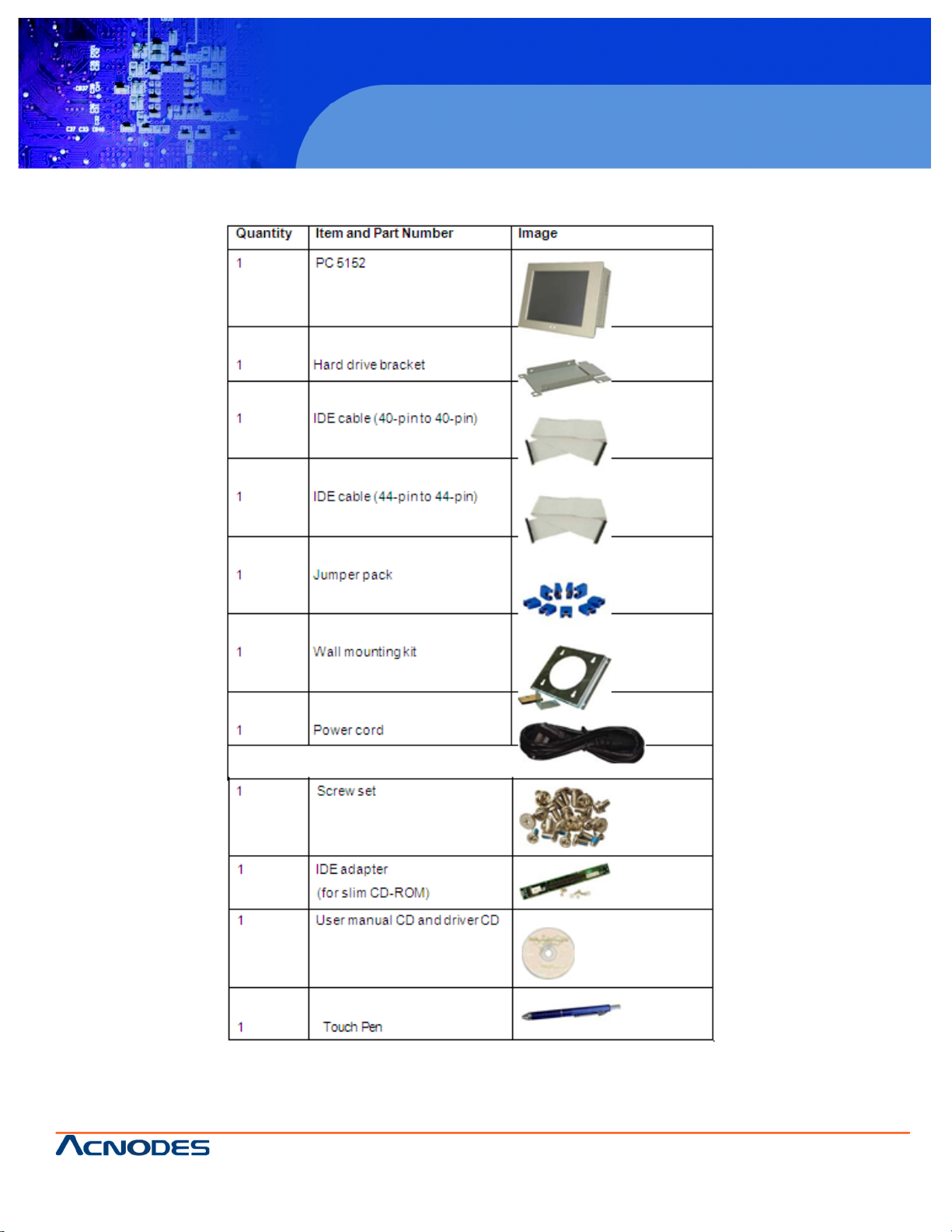
If any of the components listed in the checklist below are missing, please do not proceed with the installation. Contact the
ACNODES reseller or vendor you purchased the PC 5172 from or contact an ACNODES sales representative directly. To
contact an ACNODES sales representative, please send an email tosales@Acnodes.com.tw.
The items listed below should all be included in the PC 5172 package.
1 x PC 5172
1 x Hard drive bracket
1 x IDE cable (40-pin to 40-pin)
1 x IDE cable (44-pin to 44-pin)
1 x Jumper pack
1 x Wall mounting kit
1 x Power cord
1 x Screw set
1 x IDE adapter for slim-type optical drive
1 x Utility CD
1 x QIG (quick installation guide) Images of the above items are shown in Chapter 3.
Page 4
© Copyright 2009 Acnodes, Inc .
All right s reserv ed. Prod uct descripti on and produ ct speci fi catio ns
are subjec t to c hange witho ut notic e. For latest produ ct informat ion ,
please visi t Acnodes’ web sit e at www.a cnod es.c om.
PC 5150
15-inch touch panel PC
4
PC 5172
17-inch sunlight readable touch panel PC
661 Brea Canyon Rd., Suite 3
Walnut, CA 91789
tel: 909.598.7388, fax: 909.598.0218, www.acnodes.com
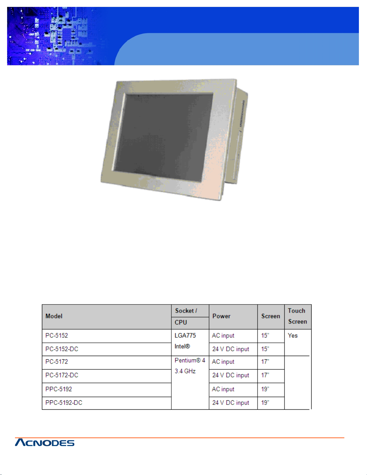
1.1 General Overview
Figure 1-1: PC 5172
The PC 5172 flat panel PC is for industrial environments like production lines and machine automation. The PC 5172
provides all the features of a PC, combined with a touch panel screen for mouse and keyboard free data input. The PC 5172
provides wired and, optionally, wireless networking for integration into company networks.
All major external device connections including USB, serial and parallel port connectors. Storage options include a 2.5" hard
drive and a CompactFlash® slot, allowing for flexibility in choosing solid state drives or traditional hard drives. A VGA output
on the rear panel allows the PC 5172 to connect to a second screen for duplicating the screen contents or extending the user interface.
1.1.1 PC 5172 Model Variations
Four ACNODES PC 5172 models are available. The models are listed in Table 1-1.
Page 5

661 Brea Canyon Rd., Suite 3
Walnut, CA 91789
tel: 909.598.7388, fax: 909.598.0218, www.acnodes.com
© Copyright 2009 Acnodes, Inc .
All right s reserved. Product descripti on and product specifi cations
are subjec t to c hange witho ut notic e. For latest produ ct informat ion ,
please visi t Acnodes’ web sit e at www.a cnod es.c om.
RMC 7152
14” short depth serverRMC 7152
14” short depth server
5
PC 5172
17-inch sunlight readable touch panel PC
1.1.2 Applications
The PC 5172 flat panel PC is designed for rigorous industrial environments where it may be exposed to both heat and
moisture. Its durability and strength also makes it an ideal choice for public access computers. Some possible applications
include:
- Automated manufacturing processes
- Public information gathering point
- Plant environment monitoring system
- Factory automation
- Manufacturing shop flow
- Equipment and device control
1.1.3 Features
Some of the features of the PC 5172 flat panel PC include:
Mainstream panel PC design with dual display function.
Aluminum die-casting front panel meet IP 65 water proof standard
Support LGA755 Intel® Core™2 Duo, Pentium® D, Pentium® 4 and
Celeron® D processors with 533/667/800/1066 MHz FSB
Dual DDR memory DIMM support up to 2 GB SDRAM
SATA connectors
High brightness industrial grade LCD panel
The following I/O ports
o 5 x COM (1 for Touch Screen)
o 4 x USB 2.0 ports
o 1 x PCI slot
o 1 x CompactFlash® slot
o 1 x VGA port
o 1 x Parallel port
Dual 10/100/Gigabit Ethernet supported
RoHS compliant
1.2 External Overview
The PC 5172 flat panel PC is comprised of an LCD screen, aluminum front panel and heavy duty steel rear and side
panels. The rear panel provides screw holes for wall and an arm mounting. The right panel provides access to a slim type
CD drive bay and a floppy disk drive bay. The bottom panel provides access to external interface connectors that include
GbE, USB 2.0, audio, parallel port, serial port connectors, VGA port, PCI card slot and a CompactFlash® card slot.
Page 6
© Copyright 2009 Acnodes, Inc .
All right s reserv ed. Prod uct descripti on and produ ct speci fi catio ns
are subjec t to c hange witho ut notic e. For latest produ ct informat ion ,
please visi t Acnodes’ web sit e at www.a cnod es.c om.
PC 5150
15-inch touch panel PC
6
PC 5172
17-inch sunlight readable touch panel PC
661 Brea Canyon Rd., Suite 3
Walnut, CA 91789
tel: 909.598.7388, fax: 909.598.0218, www.acnodes.com
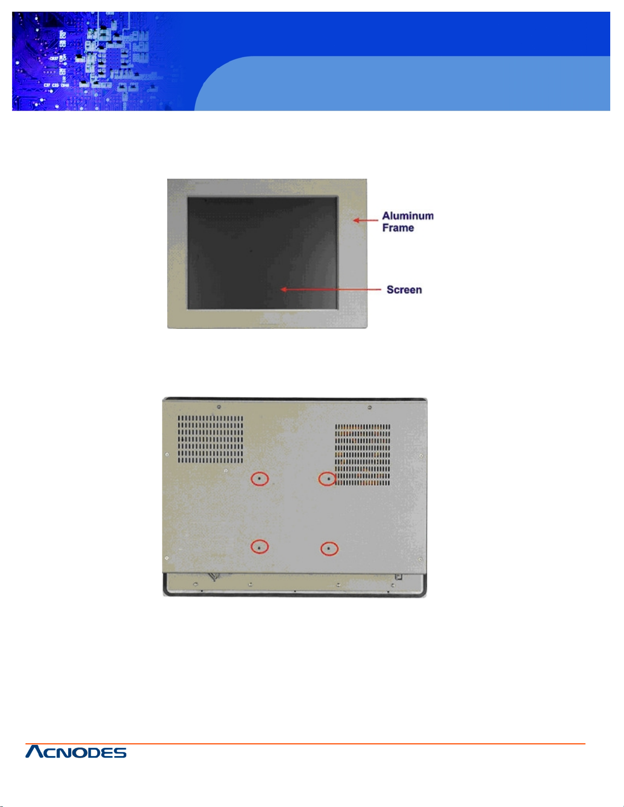
1.2.1 Front Panel
The front panel of the PC 5172 (Figure 1-2) is a flat panel TFT LCD screen surrounded by an aluminum frame.
Figure 1-2: Front View
1.2.2 Rear Panel
The rear panel has a fan vent, four VESA standard mounting holes and several retention screw holes. The VESA mounting
holes are circled in Figure 1-3.
Figure 1-3: PC 5172 Rear View
Page 7
661 Brea Canyon Rd., Suite 3
Walnut, CA 91789
tel: 909.598.7388, fax: 909.598.0218, www.acnodes.com
© Copyright 2009 Acnodes, Inc .
All right s reserved. Product descripti on and product specifi cations
are subjec t to c hange witho ut notic e. For latest produ ct informat ion ,
please visi t Acnodes’ web sit e at www.a cnod es.c om.
RMC 7152
14” short depth serverRMC 7152
14” short depth server
7
PC 5172
17-inch sunlight readable touch panel PC
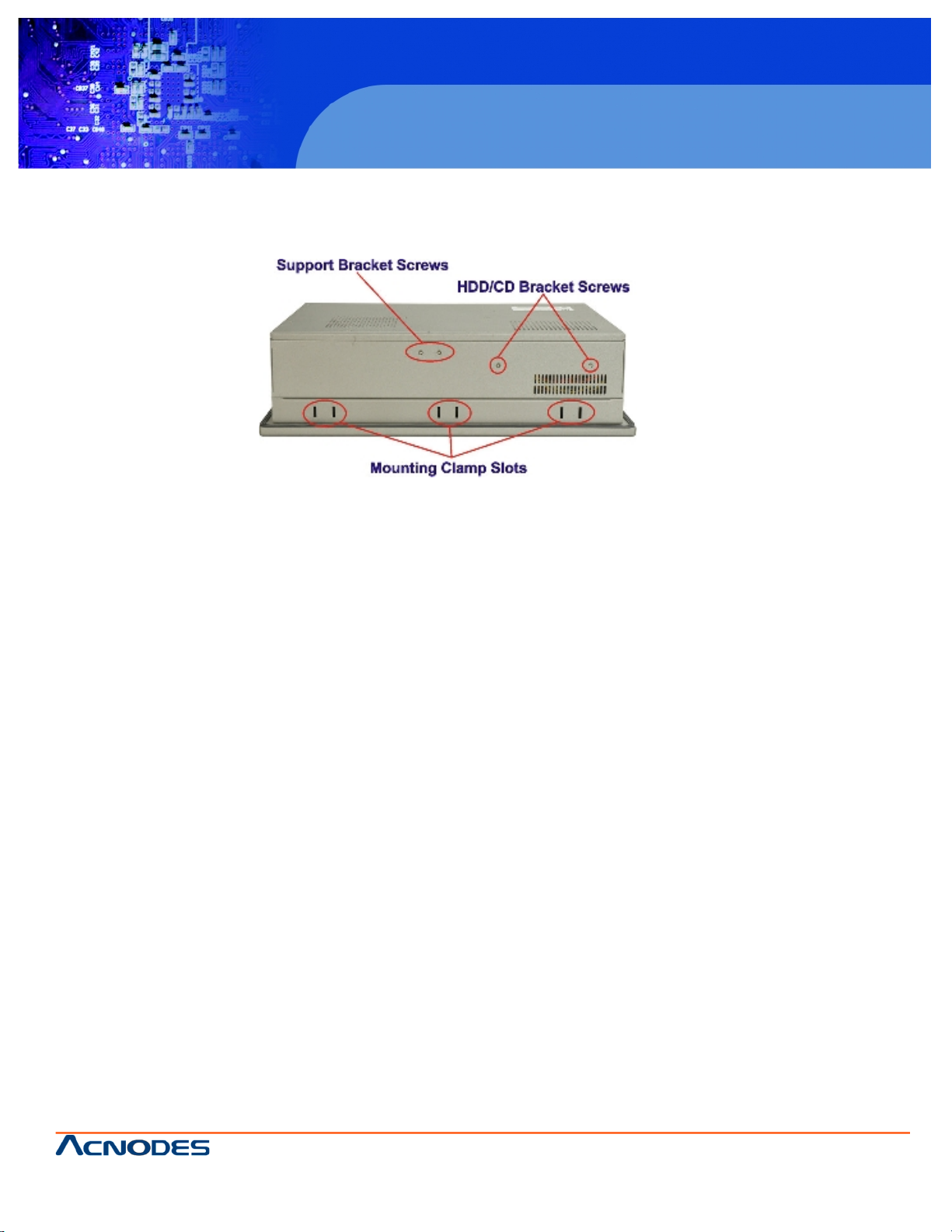
1.2.3 Top Panel
The top panel has two fan vents, eight mounting clamp slots and three retention screws for securing the drive bay bracket.
The retention screws are circled in Figure 1-4 below.
Figure 1-4: PC 5172 Top View
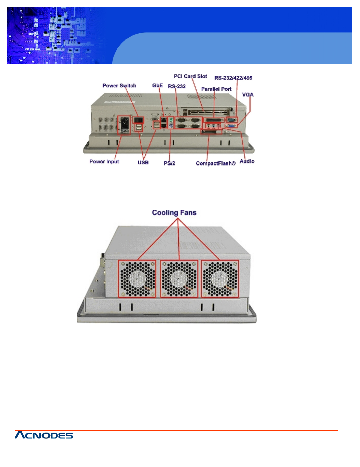
1.2.4 Bottom Panel
The bottom panel shown in Figure 1-5 has the following interfaces:
1 x Power input connector
1 x Power switch
4 x USB connectors
1 x Reset button
2 x RJ-45 GbE connectors
1 x PS/2 mouse connector
1 x PS/2 keyboard connector
5 x Serial port (COM) connectors
1 x PCI add-on card slot
1 x Parallel port connector
3 x Audio jacks
1 x VGA connector
1 x CompactFlash® slot
Page 8
© Copyright 2009 Acnodes, Inc .
All right s reserv ed. Prod uct descripti on and produ ct speci fi catio ns
are subjec t to c hange witho ut notic e. For latest produ ct informat ion ,
please visi t Acnodes’ web sit e at www.a cnod es.c om.
PC 5150
15-inch touch panel PC
8
PC 5172
17-inch sunlight readable touch panel PC
661 Brea Canyon Rd., Suite 3
Walnut, CA 91789
tel: 909.598.7388, fax: 909.598.0218, www.acnodes.com
Figure 1-5: Bottom View
1.2.5 Left Panel
The left side panel has two fan vents and four retention screws for securing the two internal fans. The retention screws are
circled in Figure 1-6.
Figure 1-6: Left View
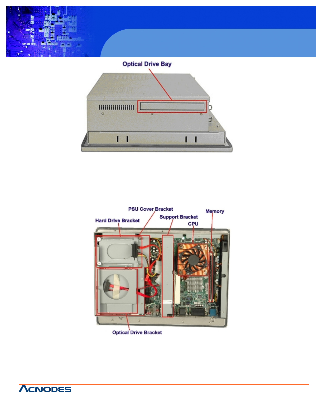
1.2.6 Right Panel
The right side panel provides access to a slim type CD drive bay and a FDD drive bay shown in Figure 1-7.
Page 9
661 Brea Canyon Rd., Suite 3
Walnut, CA 91789
tel: 909.598.7388, fax: 909.598.0218, www.acnodes.com
© Copyright 2009 Acnodes, Inc .
All right s reserved. Product descripti on and product specifi cations
are subjec t to c hange witho ut notic e. For latest produ ct informat ion ,
please visi t Acnodes’ web sit e at www.a cnod es.c om.
RMC 7152
14” short depth serverRMC 7152
14” short depth server
9
PC 5172
17-inch sunlight readable touch panel PC
Figure 1-7: Right View
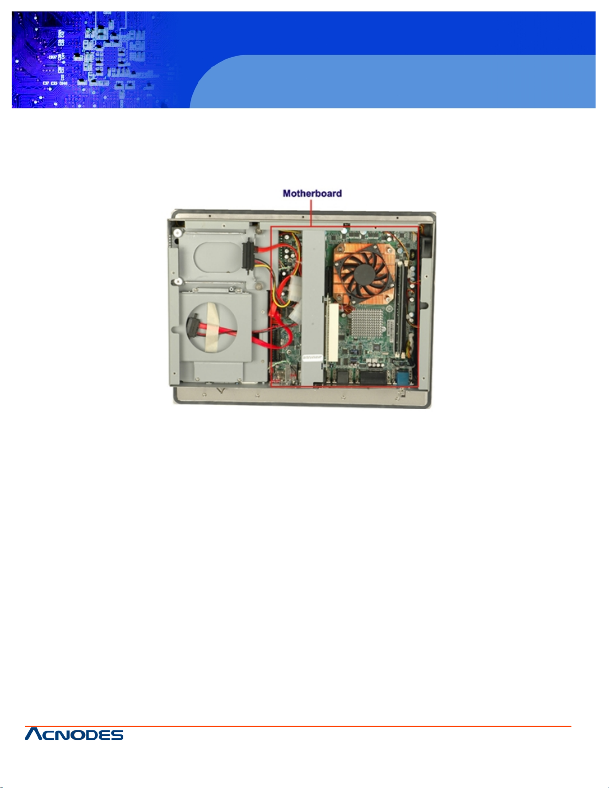
1.3 Internal Overview
The PC 5172 internal components are configured in three levels. The PSU cover bracket to the left (Figure 1-8) supports
the hard drive and optical drive brackets. Below the PSU cover bracket is the power supply. On the same level as the power
supply is the motherboard. Below the motherboard and PSU level is an LCD panel. An overview picture of the internal components is shown in Figure 1-8 below.
Figure 1-8: Internal Components
Page 10
© Copyright 2009 Acnodes, Inc .
All right s reserv ed. Prod uct descripti on and produ ct speci fi catio ns
are subjec t to c hange witho ut notic e. For latest produ ct informat ion ,
please visi t Acnodes’ web sit e at www.a cnod es.c om.
PC 5150
15-inch touch panel PC
10
PC 5172
17-inch sunlight readable touch panel PC
661 Brea Canyon Rd., Suite 3
Walnut, CA 91789
tel: 909.598.7388, fax: 909.598.0218, www.acnodes.com
2.1 Introduction
The PC 5172 flat panel PC has the following preinstalled components:
1 x Motherboard
1 x TFT LCD screen
1 x Power supply
2 x Cooling fans
The technical specifications for these components and the system are shown in the sections below.
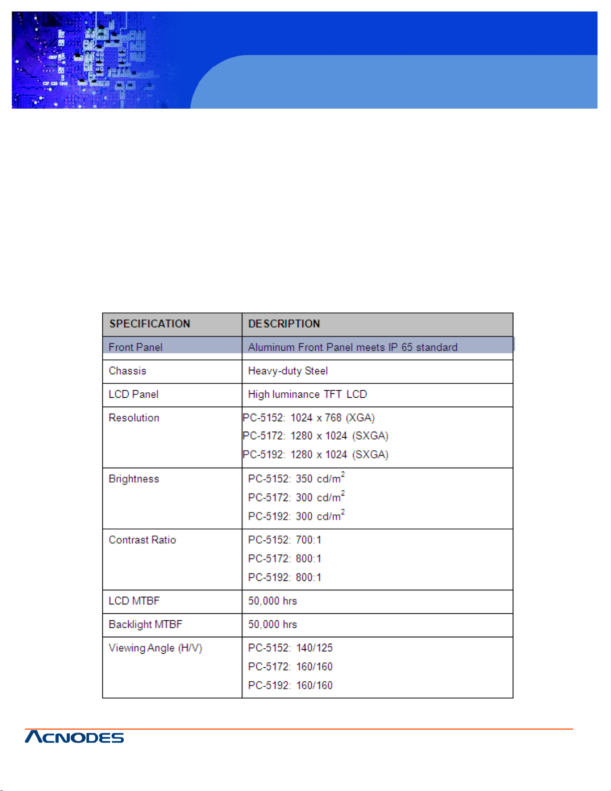
2.1.1 System Specifications
The technical specifications for the PC 5172 system are listed in Table 2-1.
Page 11

661 Brea Canyon Rd., Suite 3
Walnut, CA 91789
tel: 909.598.7388, fax: 909.598.0218, www.acnodes.com
© Copyright 2009 Acnodes, Inc .
All right s reserved. Product descripti on and product specifi cations
are subjec t to c hange witho ut notic e. For latest produ ct informat ion ,
please visi t Acnodes’ web sit e at www.a cnod es.c om.
RMC 7152
14” short depth serverRMC 7152
14” short depth server
11
PC 5172
17-inch sunlight readable touch panel PC
Page 12
© Copyright 2009 Acnodes, Inc .
All right s reserv ed. Prod uct descripti on and produ ct speci fi catio ns
are subjec t to c hange witho ut notic e. For latest produ ct informat ion ,
please visi t Acnodes’ web sit e at www.a cnod es.c om.
PC 5150
15-inch touch panel PC
12
PC 5172
17-inch sunlight readable touch panel PC
661 Brea Canyon Rd., Suite 3
Walnut, CA 91789
tel: 909.598.7388, fax: 909.598.0218, www.acnodes.com
Table 2-1: PC 5172 Specifications
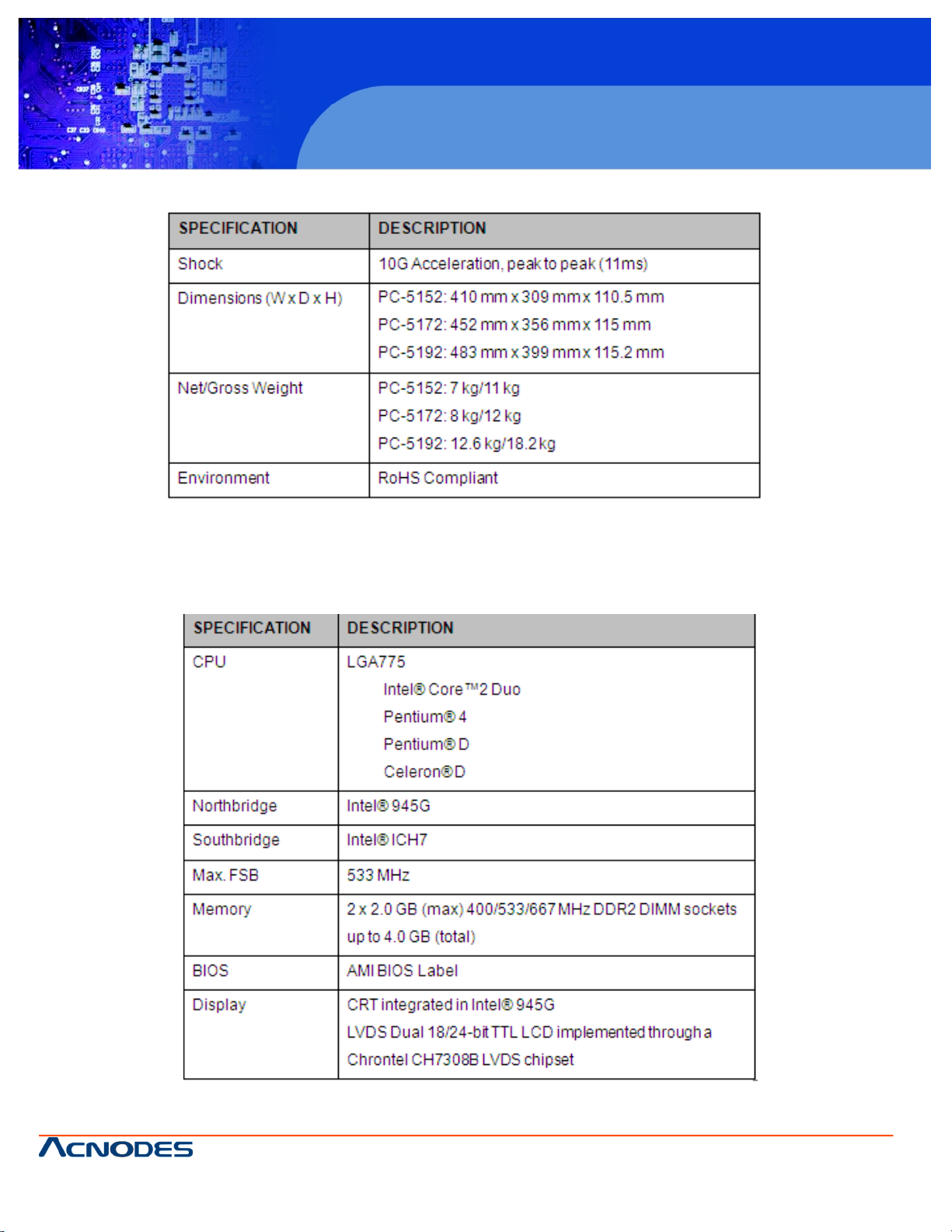
2.1.2 Motherboard Specifications
The PC 5172 comes with a 9455 motherboard. The technical specifications of the motherboard are listed in Table 2-2.
Page 13
661 Brea Canyon Rd., Suite 3
Walnut, CA 91789
tel: 909.598.7388, fax: 909.598.0218, www.acnodes.com
© Copyright 2009 Acnodes, Inc .
All right s reserved. Product descripti on and product specifi cations
are subjec t to c hange witho ut notic e. For latest produ ct informat ion ,
please visi t Acnodes’ web sit e at www.a cnod es.c om.
RMC 7152
14” short depth serverRMC 7152
14” short depth server
13
PC 5172
17-inch sunlight readable touch panel PC
Table 2-2: Motherboard Specifications
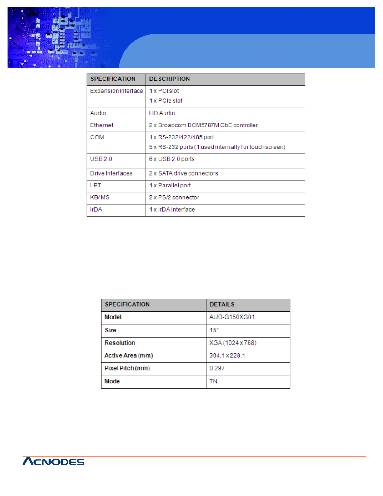
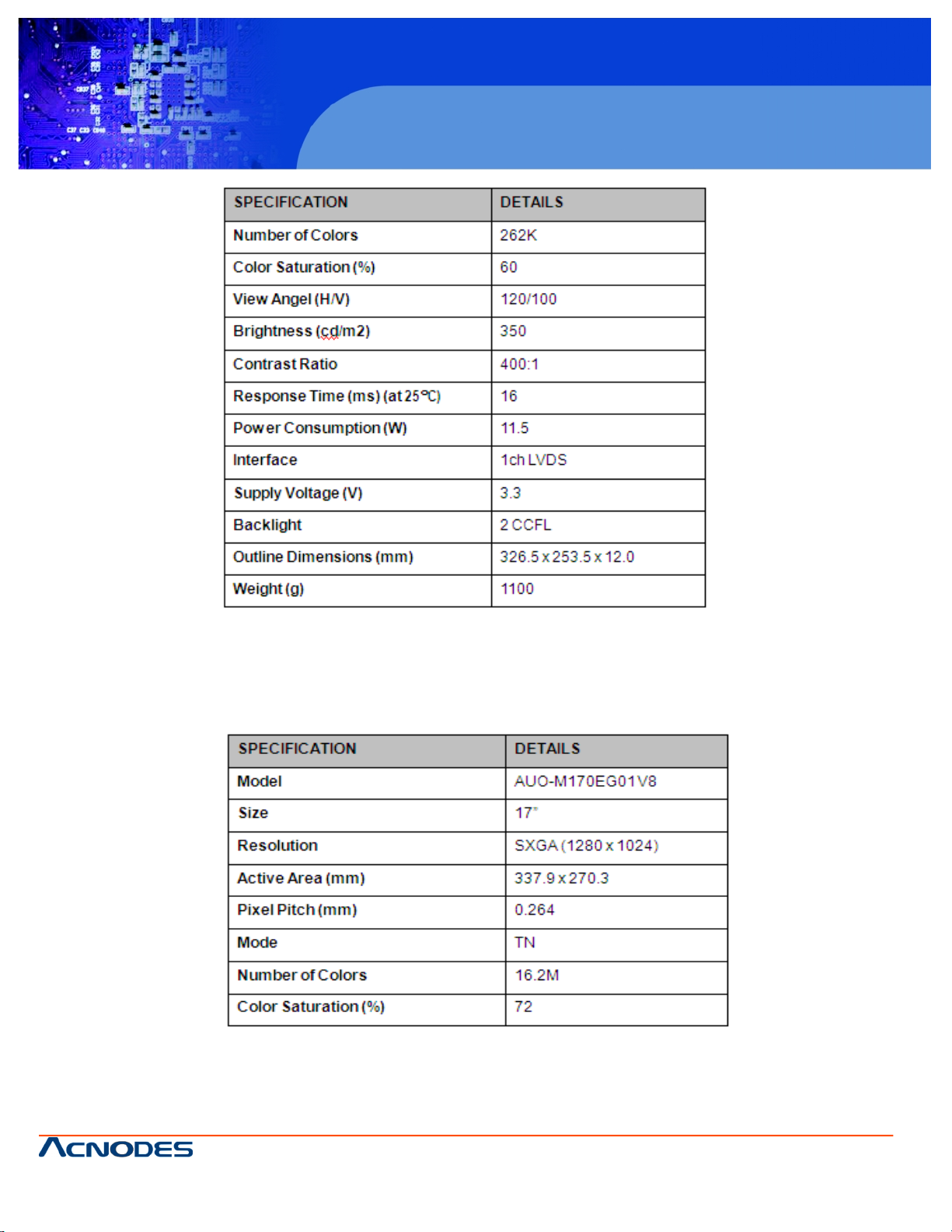
2.1.3 Flat Panel Screen
The PC 5172 comes with a flat panel TFT LCD screen. Screen specifications for each model are detailed below.
2.1.3.1 PC 5152 Screen
The PC 5172 comes with a 19" TFT LCD monitor at the front of the flat panel PC. The specifications for the LCD monitor are
shown in Table 2-3 below.
Page 14
© Copyright 2009 Acnodes, Inc .
All right s reserv ed. Prod uct descripti on and produ ct speci fi catio ns
are subjec t to c hange witho ut notic e. For latest produ ct informat ion ,
please visi t Acnodes’ web sit e at www.a cnod es.c om.
PC 5150
15-inch touch panel PC
14
PC 5172
17-inch sunlight readable touch panel PC
661 Brea Canyon Rd., Suite 3
Walnut, CA 91789
tel: 909.598.7388, fax: 909.598.0218, www.acnodes.com
Table 2-3: 17" TFT LCD Monitor Specifications
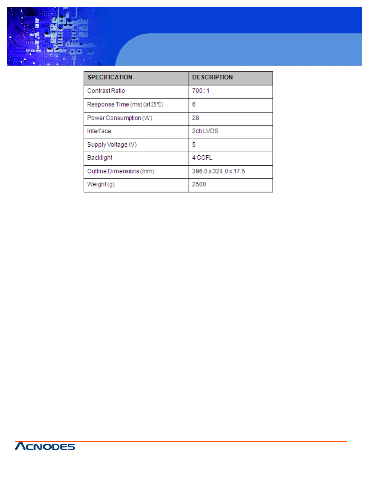
2.1.3.2 PC 5172Screen
The PC 5172 comes with a 19" TFT LCD monitor at the front of the flat panel PC. The specifications for the LCD monitor are
shown in Table 2-4 below.
Page 15

661 Brea Canyon Rd., Suite 3
Walnut, CA 91789
tel: 909.598.7388, fax: 909.598.0218, www.acnodes.com
© Copyright 2009 Acnodes, Inc .
All right s reserved. Product descripti on and product specifi cations
are subjec t to c hange witho ut notic e. For latest produ ct informat ion ,
please visi t Acnodes’ web sit e at www.a cnod es.c om.
RMC 7152
14” short depth serverRMC 7152
14” short depth server
15
PC 5172
17-inch sunlight readable touch panel PC
Table 2-4: 17" TFT LCD Monitor Specifications
2.1.3.3 PC 5192Screen
The PC 5172 comes with a 17" TFT LCD monitor at the front of the flat panel PC. The specifications for the LCD monitor are
shown in Table 2-5 below.
Page 16
© Copyright 2009 Acnodes, Inc .
All right s reserv ed. Prod uct descripti on and produ ct speci fi catio ns
are subjec t to c hange witho ut notic e. For latest produ ct informat ion ,
please visi t Acnodes’ web sit e at www.a cnod es.c om.
PC 5150
15-inch touch panel PC
16
PC 5172
17-inch sunlight readable touch panel PC
661 Brea Canyon Rd., Suite 3
Walnut, CA 91789
tel: 909.598.7388, fax: 909.598.0218, www.acnodes.com
Table 2-5: 17" TFT LCD Monitor Specifications
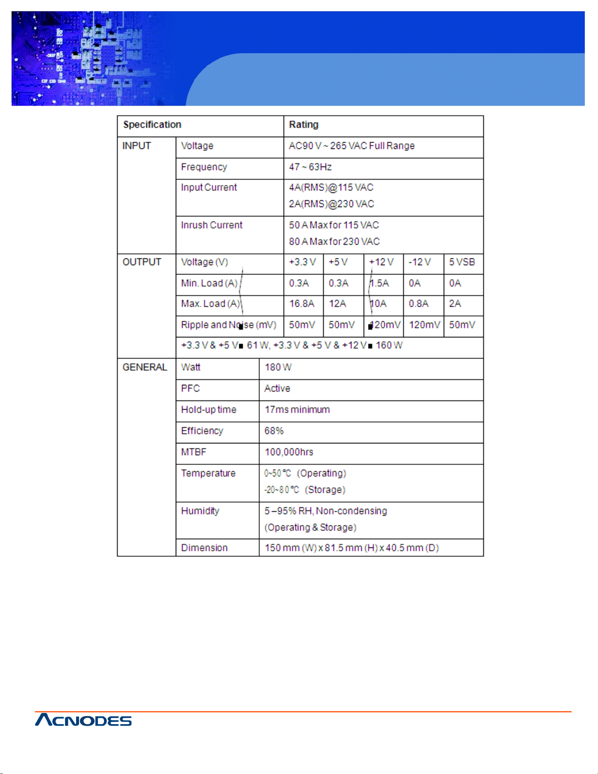
2.1.4 Power Supply
The PC 5172 flat panel PC comes with either an PS-4518AP 180 W AC-DC 1U, or PS-4520C 200 W DC 1U RoHS compliant ATX power supply. The PSUs have an MTBF greater than 100,000 hours.
2.1.4.1 PS-4518AP Power Supply
Specifications for the PS-4518AP PSU module are shown in (Table 2-6).
Page 17
661 Brea Canyon Rd., Suite 3
Walnut, CA 91789
tel: 909.598.7388, fax: 909.598.0218, www.acnodes.com
© Copyright 2009 Acnodes, Inc .
All right s reserved. Product descripti on and product specifi cations
are subjec t to c hange witho ut notic e. For latest produ ct informat ion ,
please visi t Acnodes’ web sit e at www.a cnod es.c om.
RMC 7152
14” short depth serverRMC 7152
14” short depth server
17
PC 5172
17-inch sunlight readable touch panel PC
Table 2-6: PS-4518AP Power Supply Specifications
Page 18

© Copyright 2009 Acnodes, Inc .
All right s reserv ed. Prod uct descripti on and produ ct speci fi catio ns
are subjec t to c hange witho ut notic e. For latest produ ct informat ion ,
please visi t Acnodes’ web sit e at www.a cnod es.c om.
PC 5150
15-inch touch panel PC
18
PC 5172
17-inch sunlight readable touch panel PC
661 Brea Canyon Rd., Suite 3
Walnut, CA 91789
tel: 909.598.7388, fax: 909.598.0218, www.acnodes.com
2.1.4.2 PS-4520C Power Supply
Specifications for the PS-4520C PSU module are shown in (Table 2-7).
Table 2-7: PS-4520C Power Supply Specifications
2.2 Dimensions
The dimensions of the PC 5172 are shown in the sections below.
Page 19
661 Brea Canyon Rd., Suite 3
Walnut, CA 91789
tel: 909.598.7388, fax: 909.598.0218, www.acnodes.com
© Copyright 2009 Acnodes, Inc .
All right s reserved. Product descripti on and product specifi cations
are subjec t to c hange witho ut notic e. For latest produ ct informat ion ,
please visi t Acnodes’ web sit e at www.a cnod es.c om.
RMC 7152
14” short depth serverRMC 7152
14” short depth server
19
PC 5172
17-inch sunlight readable touch panel PC
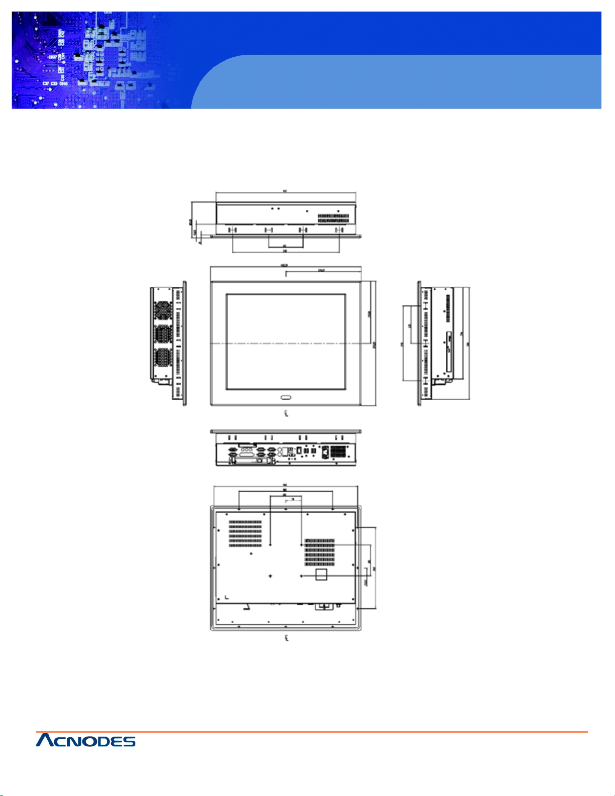
2.2.3 PC 5192 Dimension
The dimensions of the PC 5172flat panel PC are shown in Figure 2-3 below.
Page 20
© Copyright 2009 Acnodes, Inc .
All right s reserv ed. Prod uct descripti on and produ ct speci fi catio ns
are subjec t to c hange witho ut notic e. For latest produ ct informat ion ,
please visi t Acnodes’ web sit e at www.a cnod es.c om.
PC 5150
15-inch touch panel PC
20
PC 5172
17-inch sunlight readable touch panel PC
661 Brea Canyon Rd., Suite 3
Walnut, CA 91789
tel: 909.598.7388, fax: 909.598.0218, www.acnodes.com
2.3 Motherboard
The PC 5172 flat screen PC contains a 9455 motherboard. The motherboard is the heart of any computer and is responsible
for transmitting, receiving and processing data as well as driving the different on-board devices. This chapter gives a brief
introduction to the 9455 motherboard. For more complete details on the connectors and the different implementations of the
9455, please refer to the 9455 user manual.
Figure 2-4: 9455 Motherboard
2.4 CPU Support
The 9455 installed in the PC 5172 supports LGA775 Intel® Core™2 Duo, Pentium® 4, Pentium® D and Celeron® D processors.
2.5 System Chipsets
The following chipsets are preinstalled on the board:
Northbridge: Intel® 945G
Southbridge: Intel® ICH7
Specifications of these two chipsets are listed in the subsections below.
Page 21

661 Brea Canyon Rd., Suite 3
Walnut, CA 91789
tel: 909.598.7388, fax: 909.598.0218, www.acnodes.com
© Copyright 2009 Acnodes, Inc .
All right s reserved. Product descripti on and product specifi cations
are subjec t to c hange witho ut notic e. For latest produ ct informat ion ,
please visi t Acnodes’ web sit e at www.a cnod es.c om.
RMC 7152
14” short depth serverRMC 7152
14” short depth server
21
PC 5172
17-inch sunlight readable touch panel PC
2.5.1 Intel® 945G Northbridge Chipset
The Intel® 945G Northbridge chipset comes with the following features:
Supports the Intel Pentium 4 processor and Intel Celeron processor with Intel NetBurst® microarchitecture
400 MHz or 533 MHz system bus delivers a high-bandwidth connection between the processor and the platform Integrated
graphics utilizing Intel® Extreme Graphics 2 technology
Display
o Analog display support
o Dual independent pipe support
o DVO (DVOB and DVOC) support
o Dedicated Local Flat Panel (LFP) LVDS interface Intel® Embedded Graphics Drivers
o Graphics interface support
o Multi-monitor support
o Dynamic display-mode support
o Embedded video BIOS
2.5.2 ICH7 Southbridge Chipset
The ICH7 Southbridge chipset comes with the following features:
PCI Bus Interface
o New: Supports PCI Revision 2.3 Specification at 33 MHz
o 6 available PCI REQ/GNT pairs
o One PCI REQ/GNT pair can be given higher arbitration priority (intended for external 1394 host controller)
o Support for 44-bit addressing on PCI using DAC protocol Integrated LAN Controller
o Integrated ASF Management Controller
o WfM 2.0 and IEEE 802.3 Compliant
o LAN Connect Interface (LCI)
o 10/100/1000 Mbit/sec Ethernet Support
Integrated Serial ATA Host Controllers
o Independent DMA operation on two ports.
o Data transfer rates up to 1.5 Gb/s (150 MB/s).
Integrated IDE Controller
o Supports "Native Mode" Register and Interrupts
o Independent timing of up to 4 drives
o Ultra ATA/100/66/33, BMIDE and PIO modes
o Tri-state modes to enable swap bay
Interrupt Controller
o Supports up to 8 PCI interrupt pins
o Supports PCI 2.3 Message Signaled Interrupts
o Two cascaded 82C59 with 15 interrupts
o Integrated I/O APIC capability with 24 interrupts
o Supports Front Side Bus interrupt delivery
Page 22

© Copyright 2009 Acnodes, Inc .
All right s reserv ed. Prod uct descripti on and produ ct speci fi catio ns
are subjec t to c hange witho ut notic e. For latest produ ct informat ion ,
please visi t Acnodes’ web sit e at www.a cnod es.c om.
PC 5150
15-inch touch panel PC
22
PC 5172
17-inch sunlight readable touch panel PC
661 Brea Canyon Rd., Suite 3
Walnut, CA 91789
tel: 909.598.7388, fax: 909.598.0218, www.acnodes.com
High-Precision Event Timers
1.5 V operation with 3.3 V I/O
o 5 V tolerant buffers on IDE, PCI, USB Overcurrent and Legacy signals
Integrated 1.5 V Voltage Regulator (INTVR) for the Suspend wells
Enhanced DMA Controller
o Two cascaded 8237 DMA controllers
o PCI DMA: Supports PC/PCI - Includes two PC/PCI REQ#/GNT# pairs
o Supports LPC DMA
o Supports DMA Collection Buffer to provide Type-F DMA performance for all DMA channels
Real-Time Clock
o 256-byte battery-backed CMOS RAM
o Integrated oscillator components
o Lower Power DC/DC Converter implementation
2.6 Graphics Support
The ATi M690T Northbridge chipset has an integrated graphics engine that supports the following display devices:
Analog CRT
Digital LVDS
2.6.1 Analog CRT Support
The VGA port connects a peripheral monitor to the PC 5172 system. A DB-15 VGA connector on the external peripheral
interface connector panel is interfaced to the Intel® 945G Northbridge. The Intel® 945G supports analog CRT monitors with
the following features:
Supports max DAC frequency up to 400 MHz
24-bit RAMDAC support
DDC2B compliant
Up to 2048 x 1536 mode support
2.6.2 LVDS Support
The LVDS connector drives the built-in LCD panel. The 30-pin LVDS crimp connector is connected to the Chrontel CH7308B
chipset, which is connected to the Intel® 945G through the SDVO interface.
18/24-bit outputs
Up to 140 megapixels per second
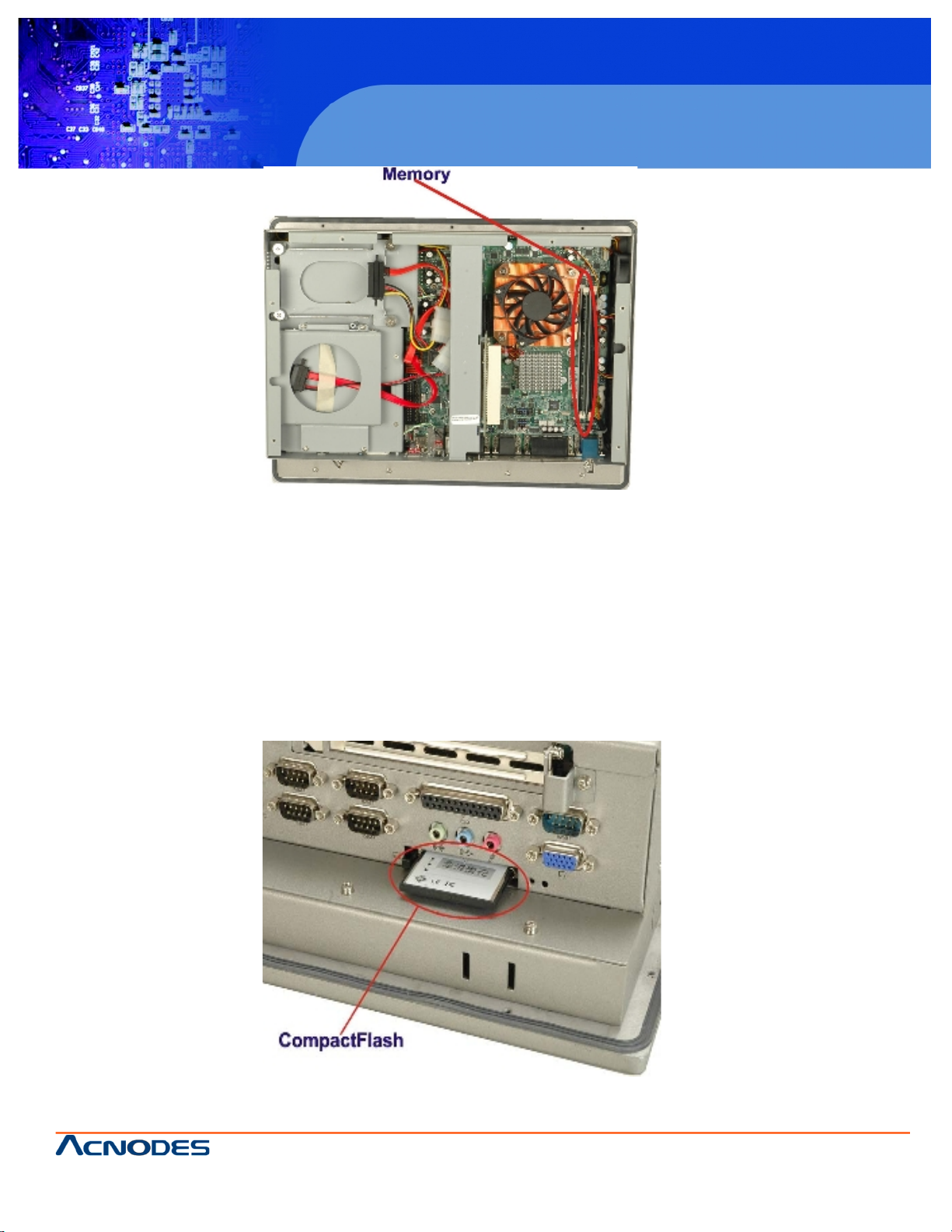
2.7 Memory
All processors supported by the PC 5172 have their own internal DDR2 memory controller. The DDR2 controller has the
following features:
Low-latency, high-bandwidth
800 MHz 128-bit DDR2 SDRAM controller
Supports one un-buffered DDR2 SO-DIMM
Each SO-DIMM has a maximum capacity of 1.0 GB
The DDR2 controller on the processor is interfaced to one SO-DIMM socket on the PC 5152 .
Page 23
661 Brea Canyon Rd., Suite 3
Walnut, CA 91789
tel: 909.598.7388, fax: 909.598.0218, www.acnodes.com
© Copyright 2009 Acnodes, Inc .
All right s reserved. Product descripti on and product specifi cations
are subjec t to c hange witho ut notic e. For latest produ ct informat ion ,
please visi t Acnodes’ web sit e at www.a cnod es.c om.
RMC 7152
14” short depth serverRMC 7152
14” short depth server
23
PC 5172
17-inch sunlight readable touch panel PC
Figure 2-5: SO-DIMM Socket
2.8 Storage
There following storage options are available:
CompactFlash®
SATA hard drive
2.8.1 CompactFlash
The CompactFlash® socket supports standard CompactFlash® Type I and CompactFlash® Type II cards. The chipset flash
interface is multiplexed with an IDE interface and can be connected to an array of industry standard NAND Flash or NOR Flash
devices. The CompactFlash® slot location is shown below.
Figure 2-6: CompactFlash® Slot
Page 24
© Copyright 2009 Acnodes, Inc .
All right s reserv ed. Prod uct descripti on and produ ct speci fi catio ns
are subjec t to c hange witho ut notic e. For latest produ ct informat ion ,
please visi t Acnodes’ web sit e at www.a cnod es.c om.
PC 5150
15-inch touch panel PC
24
PC 5172
17-inch sunlight readable touch panel PC
661 Brea Canyon Rd., Suite 3
Walnut, CA 91789
tel: 909.598.7388, fax: 909.598.0218, www.acnodes.com
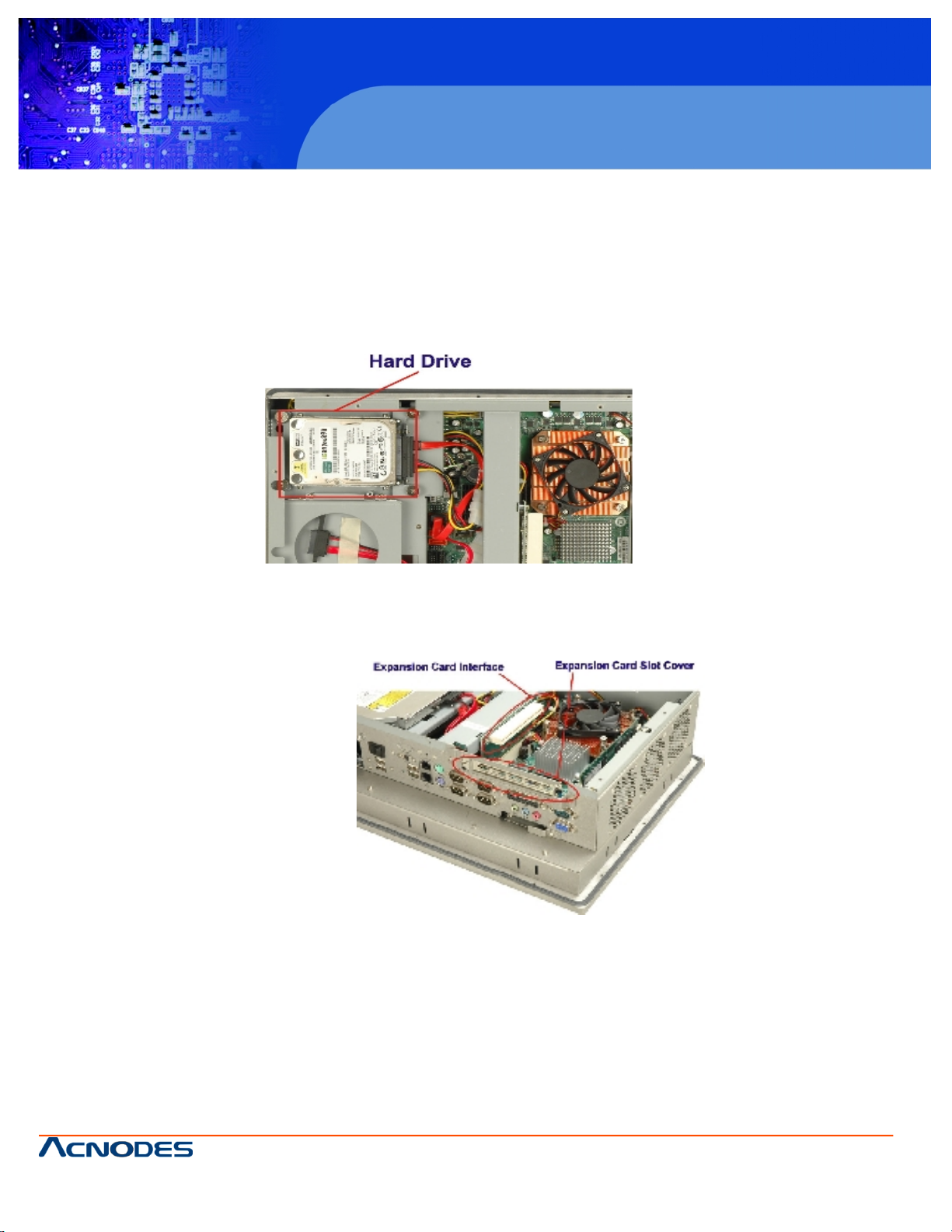
2.8.2 SATA Hard Drive
The integrated SATA controller supports two SATA drives with independent DMA operations. One SATA port is implemented
internally for the internal 2.5" SATA hard drive. The second SATA port is implemented on the external connector panel through
an eSATA connector. SATA controller specifications are listed below.
Supports two SATA drives
Supports 3.0 Gb/s data transfer speeds
Supports Serial ATA Specification, Revision 1.0a
Figure 2-7: SATA Hard Drive Slot
2.9 Expansion Slots
The PC 5172 includes either a PCI or PCIe x4 expansion card slot. The expansion card slots add additional functionality to the
PC 5172.
Figure 2-8: Expansion Card Slot
PCI cards available for the PC 5172 include:
SCSI adapter cards
Ethernet adapter cards
Modem cards
Sound cards
PCIe x4 cards available for the PC 5172 include:
Gigabit Ethernet adapter card
SATA II / RAID controller cards
TV tuner cards
Graphics cards
Firewire & USB cards
Page 25
661 Brea Canyon Rd., Suite 3
Walnut, CA 91789
tel: 909.598.7388, fax: 909.598.0218, www.acnodes.com
© Copyright 2009 Acnodes, Inc .
All right s reserved. Product descripti on and product specifi cations
are subjec t to c hange witho ut notic e. For latest produ ct informat ion ,
please visi t Acnodes’ web sit e at www.a cnod es.c om.
RMC 7152
14” short depth serverRMC 7152
14” short depth server
25
PC 5172
17-inch sunlight readable touch panel PC
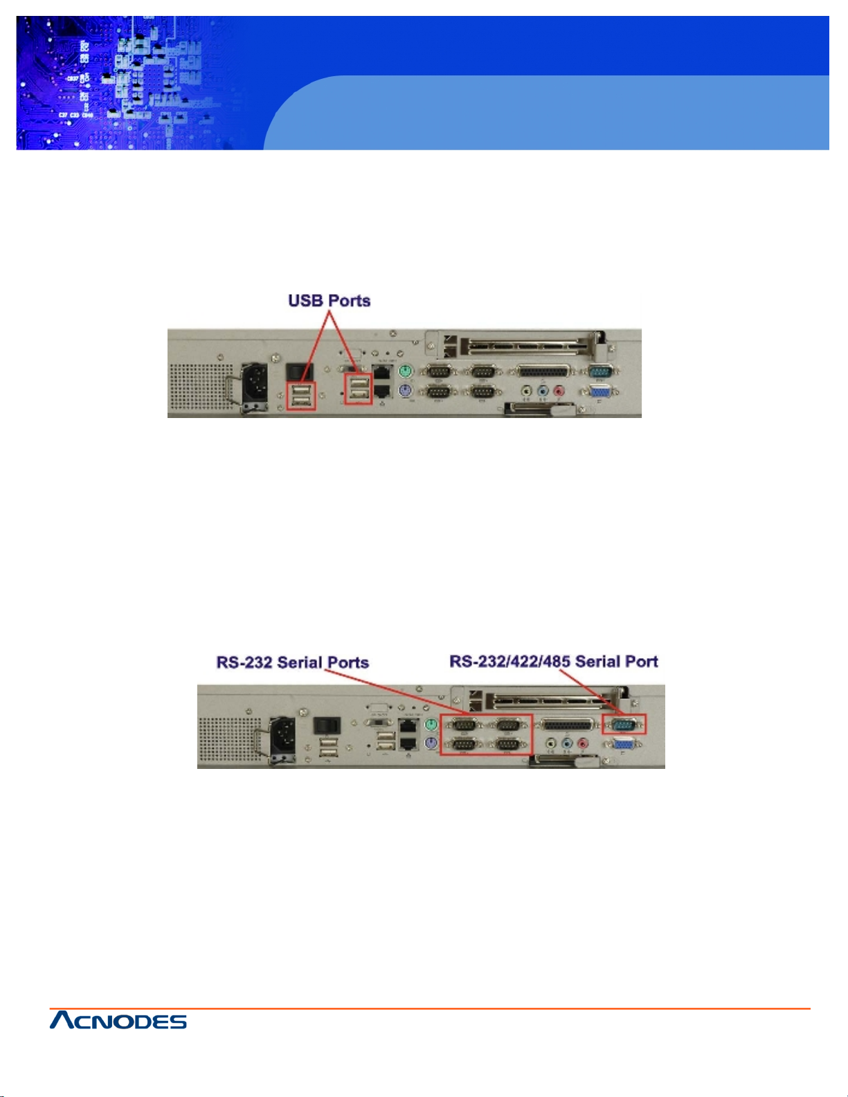
2.10 External Device Connectors
The external device connectors allow external components to be attached to the PC 5172 . The external communications device connectors are shown in the sections below.
2.10.1 USB 2.0 Ports
USB connections provide fast data transmission to external devices including USB flash disks.
Figure 2-9: USB Ports
Some of the features of the USB ports include
USB 2.0 compliant
Support for low speed (1.5 Mb/s), full speed (12 Mb/s) and hi-speed (480 Mb/s) USB devices
Hotplugging capabilities
2.10.2 Serial Ports
Serial ports provide communications to external devices. Four of the external serial ports provide short-range communications,
while one provides for longer range communication.
Figure 2-10: Serial Ports
Some features of the serial ports include:
RS-232 transmission protocol for easy connection to devices with a standard
RS-232 interface
RS-422 and RS-485 transmission capabilities for longer distance connections.
Page 26

© Copyright 2009 Acnodes, Inc .
All right s reserv ed. Prod uct descripti on and produ ct speci fi catio ns
are subjec t to c hange witho ut notic e. For latest produ ct informat ion ,
please visi t Acnodes’ web sit e at www.a cnod es.c om.
PC 5150
15-inch touch panel PC
26
PC 5172
17-inch sunlight readable touch panel PC
661 Brea Canyon Rd., Suite 3
Walnut, CA 91789
tel: 909.598.7388, fax: 909.598.0218, www.acnodes.com
The parallel port can be programmed for machine control, or used in the standard setup for parallel port printers and other
devices that use a standard parallel port.
Figure 2-11: Parallel Port
Some of the features of the parallel port include:
Programmable pin functions for customized applications
Standard setup connects to devices with a standard parallel port, like printers
2.11 Gigabit Ethernet
The Broadcom BCM5787M PCI Express (PCIe) GbE controller is a 10/100/1000BASE-T Ethernet LAN controller. The
BCM5787M combines a triple-speed IEEE 802.3 compliant Media Access Controller (MAC) with a triple-speed Ethernet
transceiver, a PCIe bus interface, and an on-chip buffer memory.
Figure 2-12: Ethernet
Some of the BCM5787 controller features are listed below:
Integrated 10/100/1000BASE-T transceiver
Automatic MDI crossover function
PCIe v1.0a
10/100/1000BASE-T full/half-duplex MAC
Wake on LAN support meeting the ACPI requirements
Statistics for SNMP MIB II, Ethernet-like MIB, and Ethernet MIB (802.3z, clause 30)
Serial EEPROM or serial flash support
JTAG support
Page 27

661 Brea Canyon Rd., Suite 3
Walnut, CA 91789
tel: 909.598.7388, fax: 909.598.0218, www.acnodes.com
© Copyright 2009 Acnodes, Inc .
All right s reserved. Product descripti on and product specifi cations
are subjec t to c hange witho ut notic e. For latest produ ct informat ion ,
please visi t Acnodes’ web sit e at www.a cnod es.c om.
RMC 7152
14” short depth serverRMC 7152
14” short depth server
27
PC 5172
17-inch sunlight readable touch panel PC
2.12 Front Panel
The front panel of the PC 5172 consists of an LCD monitor and a touch screen panel.
2.12.1 Flat Screen
The PC 5172 comes with a TFT LCD monitor. The tough construction of the TFT monitor allows the PC 5172 to withstand the
conditions it is likely to be exposed to during regular use. Some of the specifications of the TFT monitors are shown below:
Pixel pitch of 0.297 mm or less
700:1 contrast ratio or better
300 cd/m2 or greater
8 msec optical response time or less
0oC to 50oC operating temperature
2.12.2 Touch Screen
The touch screen panel on the PC 5172 allows complete user interaction without the need for a keyboard or mouse. Some of
the features of the touch panel are listed below.
5-wire analog resistive type
78% transmission
Control chipset built onto the motherboard
-10oC to 50oC operating temperature
7 V maximum voltage
2.13 OEM Options
Some of the peripheral device connectors are not connected to any devices. These connectors are reserved for OEM
customizations. For a customized option, please contact the vendor, reseller, or ACNODES sales representative.
Page 28

© Copyright 2009 Acnodes, Inc .
All right s reserv ed. Prod uct descripti on and produ ct speci fi catio ns
are subjec t to c hange witho ut notic e. For latest produ ct informat ion ,
please visi t Acnodes’ web sit e at www.a cnod es.c om.
PC 5150
15-inch touch panel PC
28
PC 5172
17-inch sunlight readable touch panel PC
661 Brea Canyon Rd., Suite 3
Walnut, CA 91789
tel: 909.598.7388, fax: 909.598.0218, www.acnodes.com
3.1 Anti-static Precautions
WARNING!
Failure to take ESD precautions during the installation of the PC 5172 may result in permanent damage to
the PC 5172 and severe injury to the user.
Electrostatic discharge (ESD) can cause serious damage to electronic components, including the PC 5172 . Dry climates are
especially susceptible to ESD. It is critical that the following anti-static precautions are strictly adhered to whenever handling
the PC 5172 or any other electrical component.
Wear an anti-static wristband - Wearing a simple anti-static wristband can help to prevent ESD from damaging the PC 5172
.
Self-grounding - Touch a grounded conducting material before handling and periodically while handling the PC 5172.
Use an anti-static pad - When configuring the PC 5172 , place it on an antic- static pad to reduce the possibility of ESD
damage.
Only handle the edges of the PC 5172 - When handling the PC 5172 , hold it by its edges.
3.2 Unpacking Precautions
When the PC 5172 is unpacked, please do the following:
Follow the anti-static precautions outlined in Section 3.1.
Make sure the packing box is facing upwards so the PC 5152 does not fall out of the box.
Make sure all the components shown in Section 3.3 are present.
3.3 Package Contents
NOTE: If any components listed in the checklist below are missing, do not proceed with the installation. Contact the
ACNODES reseller or vendor the PC 5172 was purchased from or contact an ACNODES sales representative directly by sending an email to sales@Acnodes.com.tw.
The PC 5172 is shipped with the following components:
Page 29
661 Brea Canyon Rd., Suite 3
Walnut, CA 91789
tel: 909.598.7388, fax: 909.598.0218, www.acnodes.com
© Copyright 2009 Acnodes, Inc .
All right s reserved. Product descripti on and product specifi cations
are subjec t to c hange witho ut notic e. For latest produ ct informat ion ,
please visi t Acnodes’ web sit e at www.a cnod es.c om.
RMC 7152
14” short depth serverRMC 7152
14” short depth server
29
PC 5172
17-inch sunlight readable touch panel PC
Table 3-1: Package List Contents
Page 30

© Copyright 2009 Acnodes, Inc .
All right s reserv ed. Prod uct descripti on and produ ct speci fi catio ns
are subjec t to c hange witho ut notic e. For latest produ ct informat ion ,
please visi t Acnodes’ web sit e at www.a cnod es.c om.
PC 5150
15-inch touch panel PC
30
PC 5172
17-inch sunlight readable touch panel PC
661 Brea Canyon Rd., Suite 3
Walnut, CA 91789
tel: 909.598.7388, fax: 909.598.0218, www.acnodes.com
4.1 Installation Precautions
When installing the PC 5172 , please follow the precautions listed below:
Turn power off: When installing the PC 5172 make sure the power is off. Failing to turn off the power may cause severe
injury to the body and/or damage to the system.
Certified Engineers: Only certified engineers should install and modify on-board functions.
Mounting: The PC 5172 is a heavy device. When mounting the system onto a rack, panel, wall or arm please make
sure that at least two people are assisting with the procedure.
Anti-static Discharge: If a user open the rear panel of the PC 5172 , to configure the jumpers or plug in added peripheral devices, ground themselves first and wear and anti-static wristband.
4.2 Preinstalled Components
The following components are all preinstalled.
Motherboard
TFT LCD
Touch screen
Power switch
Power supply
Inverter board
PCI riser card
System cooling fans
Preinstalled OEM customizations may include the following.
CPU
HDD
CD drive
DIMM
Removal and reinstallation of some of the components are described in Chapter 4.
4.3 Installation and Configuration Steps
The following installation steps must be followed.
Step 1: Unpack the PC 5172 .
Step 2: Set the jumper settings.
Step 3: Install HDD, CompactFlash® and CD drive.
Step 4: Mount the PC 5172 flat panel PC.
Step 5: Connect peripheral devices to the bottom panel of the PC 5172 .
Step 6: Configure the system.
Page 31

661 Brea Canyon Rd., Suite 3
Walnut, CA 91789
tel: 909.598.7388, fax: 909.598.0218, www.acnodes.com
© Copyright 2009 Acnodes, Inc .
All right s reserved. Product descripti on and product specifi cations
are subjec t to c hange witho ut notic e. For latest produ ct informat ion ,
please visi t Acnodes’ web sit e at www.a cnod es.c om.
RMC 7152
14” short depth serverRMC 7152
14” short depth server
31
PC 5172
17-inch sunlight readable touch panel PC
4.4 Remove the Back Cover
Remove all the retention screws on the back cover. Lift the cover up to remove (Figure 4-1).
Figure 4-1: Back Cover Retention Screws
4.5 Jumper Settings
NOTE: These jumper settings and the jumper locations are described in detail in the user manual that came with the 9455
motherboard. Please refer to the manual for more detailed descriptions of the jumper settings.
NOTE: A jumper is a metal bridge that is used to close an electrical circuit. It consists of two metal pins and a small metal
clip (often protected by a plastic cover that slides over the pins to connect them. To CLOSE/SHORT a jumper means connecting the pins of the jumper with the plastic clip and to OPEN a jumper means removing the plastic clip from a jumper.
The 9455 comes with fifteen jumpers (Table 3-1).
Page 32

© Copyright 2009 Acnodes, Inc .
All right s reserv ed. Prod uct descripti on and produ ct speci fi catio ns
are subjec t to c hange witho ut notic e. For latest produ ct informat ion ,
please visi t Acnodes’ web sit e at www.a cnod es.c om.
PC 5150
15-inch touch panel PC
32
PC 5172
17-inch sunlight readable touch panel PC
661 Brea Canyon Rd., Suite 3
Walnut, CA 91789
tel: 909.598.7388, fax: 909.598.0218, www.acnodes.com
4.5.1 AT/ATX Power Selection (AT_PWR_SW1)
The AT/ATX power selection switch selects AT or ATX power for the PC 5172. ATX power has more power saving capabilities
than AT power. The AT/ATX selection jumper is connected to the AT/ATX switch on the I/O panel of the PC 5172.
Table 4-2: AT/ATX Power Selection
4.5.2 Clear CMOS Setup (JP2)
If the motherboard fails to boot due to improper BIOS settings, use this jumper to clear the CMOS data and reset the system
BIOS information. To do this, use the jumper cap to close pins 2 and 3 for a few seconds then reinstall the jumper clip back to
pins 1 and 2.
If the "CMOS Settings Wrong" message displays during the boot up process, try to correct the fault by pressing the F1 to enter
the CMOS Setup menu. Then do one of the following:
Enter the correct CMOS setting
Load Optimal Defaults
After one of the above has been done, save the changes and exit the CMOS Setup menu.
Table 4-3: Clear CMOS Jumper Settings
4.5.3 Monitor Setup (JP1)
WARNING: Do not change these settings. They are set for the installed LCD panel. Using different settings on the preinstalled
monitor can destroy it.
The monitor setup jumper sets the default settings for all monitors connected to the PC 5172 .
Pins 1-4 adjust the resolution of the screen.
Page 33

661 Brea Canyon Rd., Suite 3
Walnut, CA 91789
tel: 909.598.7388, fax: 909.598.0218, www.acnodes.com
© Copyright 2009 Acnodes, Inc .
All right s reserved. Product descripti on and product specifi cations
are subjec t to c hange witho ut notic e. For latest produ ct informat ion ,
please visi t Acnodes’ web sit e at www.a cnod es.c om.
RMC 7152
14” short depth serverRMC 7152
14” short depth server
33
PC 5172
17-inch sunlight readable touch panel PC
Table 4-4: LCD Resolution Settings
Pins 5-8 adjust the monitor setup on the system.
Table 4-5: Monitor Settings
Page 34

© Copyright 2009 Acnodes, Inc .
All right s reserv ed. Prod uct descripti on and produ ct speci fi catio ns
are subjec t to c hange witho ut notic e. For latest produ ct informat ion ,
please visi t Acnodes’ web sit e at www.a cnod es.c om.
PC 5150
15-inch touch panel PC
34
PC 5172
17-inch sunlight readable touch panel PC
661 Brea Canyon Rd., Suite 3
Walnut, CA 91789
tel: 909.598.7388, fax: 909.598.0218, www.acnodes.com
4.5.5 COM Port RI and Voltage Selection (JP3, JP4, JP5, JP6, JP8)
Use the COM port settings jumpers to select the voltage of serial port pin 9.
Table 4-7: COM1 RI and Voltage Selection Jumper
Table 4-8: COM2 RI and Voltage Selection Jumper
Table 4-9: COM3 RI and Voltage Selection Jumper
Table 4-10: COM4 RI and Voltage Selection Jumper
Table 4-11: COM5 RI and Voltage Selection Jumper
Page 35

661 Brea Canyon Rd., Suite 3
Walnut, CA 91789
tel: 909.598.7388, fax: 909.598.0218, www.acnodes.com
© Copyright 2009 Acnodes, Inc .
All right s reserved. Product descripti on and product specifi cations
are subjec t to c hange witho ut notic e. For latest produ ct informat ion ,
please visi t Acnodes’ web sit e at www.a cnod es.c om.
RMC 7152
14” short depth serverRMC 7152
14” short depth server
35
PC 5172
17-inch sunlight readable touch panel PC
4.5.6 COM5 RS-232/422/485 Settings
To enable RS-232, RS-422 or RS-485 on COM5, all the following jumpers should be setup.
4.5.6.1 COM5 RS-232/422/485 RX Select (J2)
Jumper J2 sets the COM5 serial port as RS-232, RS-422 or RS-485.
Table 4-12: COM5 RS-232/422/485 RX Select
4.5.6.2 COM5 RS-422/485 TX Select (J3)
Jumper J3 sets the COM5 serial port as RS-422 or RS-485.
4.5.6.3 COM5 D-Sub Pinout Selection (J4)
Jumper J4 sets the external COM5 serial port as RS-232 or RS-422/485.
Table 4-13: COM5 RS-422/485 TX Select
4.5.6.3 COM5 D-Sub Pinout Selection (J4)
Jumper J4 sets the external COM5 serial port as RS-232 or RS-422/485.
4.5.6.4 COM5 Termination Resistors (J5, J6)
The termination resistors J5 and J6 can remedy communication errors for
RS-422/485 setups with cables over 1.5 km in length.
4.5.7 LCD Voltage Settings (JP9)
WARNING: Do not change these settings. They are set for the
installed LCD panel. Using different settings on the preinstalled
monitor can destroy it. The LCD setup sets the voltage and default
monitor settings on the PC 5152 .
Page 36

© Copyright 2009 Acnodes, Inc .
All right s reserv ed. Prod uct descripti on and produ ct speci fi catio ns
are subjec t to c hange witho ut notic e. For latest produ ct informat ion ,
please visi t Acnodes’ web sit e at www.a cnod es.c om.
PC 5150
15-inch touch panel PC
36
PC 5172
17-inch sunlight readable touch panel PC
661 Brea Canyon Rd., Suite 3
Walnut, CA 91789
tel: 909.598.7388, fax: 909.598.0218, www.acnodes.com
4.5.8 Touch Screen Selection (JP7)
The touch screen selection jumper selects the type of touch screen panel connected to the system.
Table 4-17: Touch Screen Selection
4.6 Drive Installation
The drive installation process is shown in the sections below. The installation process of the following drives are shown.
4.6.1 Hard Drive Installation................................................................... 47
4.6.2 CompactFlash® Installation ........................................................... 50
4.6.3 CD Drive Installation ..................................................................... 51
4.6.1 Hard Drive Installation
To install a HDD, please follow the steps below:
Step 1: Remove the back cover (Section 4.4).
Step 2: The HDD bracket is attached to the elevated platform by four retention screws. Remove the four retention screws
from the elevated platform (Figure 4-2).
Figure 4-2: HDD Retention Screws
Step 3: Attach the SATA connector cable to the bracket.
Page 37

661 Brea Canyon Rd., Suite 3
Walnut, CA 91789
tel: 909.598.7388, fax: 909.598.0218, www.acnodes.com
© Copyright 2009 Acnodes, Inc .
All right s reserved. Product descripti on and product specifi cations
are subjec t to c hange witho ut notic e. For latest produ ct informat ion ,
please visi t Acnodes’ web sit e at www.a cnod es.c om.
RMC 7152
14” short depth serverRMC 7152
14” short depth server
37
PC 5172
17-inch sunlight readable touch panel PC
Figure 4-3: HDD SATA Connector
Step 4: Attach the hard drive in the bracket. To do this, slide the hard drive onto the bracket until it connects with the SATA
connector at the back. Fasten the four retention screws on the side.
Figure 4-4: HDD Retention Screws
Step 5: Install the hard drive bracket (with hard drive and SATA cable attached) into the PC 5152 and fasten the four hard drive
bracket screws.
Figure 4-5: HDD Retention Screws
Page 38

© Copyright 2009 Acnodes, Inc .
All right s reserv ed. Prod uct descripti on and produ ct speci fi catio ns
are subjec t to c hange witho ut notic e. For latest produ ct informat ion ,
please visi t Acnodes’ web sit e at www.a cnod es.c om.
PC 5150
15-inch touch panel PC
38
PC 5172
17-inch sunlight readable touch panel PC
661 Brea Canyon Rd., Suite 3
Walnut, CA 91789
tel: 909.598.7388, fax: 909.598.0218, www.acnodes.com
4.6.2 CompactFlash® Installation
To install the CompactFlash® card, please follow the steps below:
Step 1: Undo the CompactFlash® slot cover screw and remove the CompactFlash cover plate.
Figure 4-6: CompactFlash® Cover Plate
Step 2: Insert the CompactFlash® card into the slot.
Figure 4-7: CompactFlash® Slot
Step 3: Fasten the CompactFlash® cover plate.
Figure 4-8: CompactFlash® Cover Plate
Page 39

661 Brea Canyon Rd., Suite 3
Walnut, CA 91789
tel: 909.598.7388, fax: 909.598.0218, www.acnodes.com
© Copyright 2009 Acnodes, Inc .
All right s reserved. Product descripti on and product specifi cations
are subjec t to c hange witho ut notic e. For latest produ ct informat ion ,
please visi t Acnodes’ web sit e at www.a cnod es.c om.
RMC 7152
14” short depth serverRMC 7152
14” short depth server
39
PC 5172
17-inch sunlight readable touch panel PC
4.6.3 CD Drive Installation
To install a CD drive, please follow the steps below.
Step 1: Remove the back cover (Section 4.4).
Step 2: Attach the CD drive adapter to the CD-ROM if it is an IDE drive (if it is a SATA drive, proceed to Step 5:). Attach a CD
drive adapter to a CD drive by aligning the two retention screw holes in the CD drive adapter with the retention screw holes on
the rear side of the CD drive.
Step 3: Place two spacers between the CD drive and CD drive adapter.
Step 4: Insert two retention screws and secure the adapter to the CD drive (Figure 4-9).
Figure 4-9: CD Drive Adapter Installation
Step 5: Undo the optical drive bracket screws and remove the optical drive bracket.
Figure 4-10: CD Drive Retention Screws
Step 6: Remove the four screws from the optical drive bracket assembly. Remove the blank drive plate.
Page 40

© Copyright 2009 Acnodes, Inc .
All right s reserv ed. Prod uct descripti on and produ ct speci fi catio ns
are subjec t to c hange witho ut notic e. For latest produ ct informat ion ,
please visi t Acnodes’ web sit e at www.a cnod es.c om.
PC 5150
15-inch touch panel PC
40
PC 5172
17-inch sunlight readable touch panel PC
661 Brea Canyon Rd., Suite 3
Walnut, CA 91789
tel: 909.598.7388, fax: 909.598.0218, www.acnodes.com
Figure 4-10: CD Drive Retention Screws
Step 6: Remove the four screws from the optical drive bracket assembly. Remove the blank drive plate.
Figure 4-11: Optical Drive Blank Plate Assembly
Step 7: Install the optical drive in the same position as the previously removed blank optical drive plate. Fasten the same
four screws to attach the optical drive to the bracket.
Figure 4-12: Optical Drive Screws
Step 8: Attach the SATA cable to the back of the optical drive and fasten the SATA cable screws.
Page 41

661 Brea Canyon Rd., Suite 3
Walnut, CA 91789
tel: 909.598.7388, fax: 909.598.0218, www.acnodes.com
© Copyright 2009 Acnodes, Inc .
All right s reserved. Product descripti on and product specifi cations
are subjec t to c hange witho ut notic e. For latest produ ct informat ion ,
please visi t Acnodes’ web sit e at www.a cnod es.c om.
RMC 7152
14” short depth serverRMC 7152
14” short depth server
41
PC 5172
17-inch sunlight readable touch panel PC
Figure 4-13: Optical Drive SATA Cable
Step 9: Reinstall the optical drive bracket into the PC 5172 and fasten the optical bracket screws.
Figure 4-14: Optical Drive Bracket Screws
4.7 Mounting the System
WARNING! When mounting the PC 5172 flat panel PC onto an arm, wall or into a panel, it is advisable to have more than one
person help with the installation to prevent accidental damage to the panel and avoid personal injury.
The methods of mounting the PC 5172 are:
- Wall mounting
- Panel mounting
- Arm mounting
- Rack mounting
The mounting methods are fully described below.
Page 42

© Copyright 2009 Acnodes, Inc .
All right s reserv ed. Prod uct descripti on and produ ct speci fi catio ns
are subjec t to c hange witho ut notic e. For latest produ ct informat ion ,
please visi t Acnodes’ web sit e at www.a cnod es.c om.
PC 5150
15-inch touch panel PC
42
PC 5172
17-inch sunlight readable touch panel PC
661 Brea Canyon Rd., Suite 3
Walnut, CA 91789
tel: 909.598.7388, fax: 909.598.0218, www.acnodes.com
4.7.1 Wall Mounting
To mount the PC 5172 flat panel PC onto a wall, please follow the steps below.
Step 1: Select the location on the wall for the wall-mounting bracket.
Step 2: Carefully mark the locations of the four bracket screw holes on the wall.
Step 3: Drill four pilot holes at the marked locations on the wall for the bracket retention screws.
Step 4: Align the wall-mounting bracket screw holes with the pilot holes.
Step 5: Secure the mounting-bracket to the wall by inserting the retention screws into the four pilot holes and tightening them
(see Figure 3-11).
Figure 4-15: Wall-mounting Bracket
Step 6: Insert the four monitor mounting screws provided in the wall mounting kit into the four screw holes on the real panel of
the monitor and tighten until the screw shank is secured against the rear panel (see Figure 3-12).
Step 7: Align the mounting screws on the monitor rear panel with the mounting holes on the bracket.
Step 8: Carefully insert the screws through the holes and gently pull the monitor downwards until the monitor rests securely in
the slotted holes (see Figure 3-12). Ensure that all four of the mounting screws fit snuggly into their respective slotted holes.
NOTE: In the diagram below the bracket is already installed on the wall.
Page 43

661 Brea Canyon Rd., Suite 3
Walnut, CA 91789
tel: 909.598.7388, fax: 909.598.0218, www.acnodes.com
© Copyright 2009 Acnodes, Inc .
All right s reserved. Product descripti on and product specifi cations
are subjec t to c hange witho ut notic e. For latest produ ct informat ion ,
please visi t Acnodes’ web sit e at www.a cnod es.c om.
RMC 7152
14” short depth serverRMC 7152
14” short depth server
43
PC 5172
17-inch sunlight readable touch panel PC
Figure 4-16: Mount the Chassis
Step 9: Secure the panel PC with the wall-mounting kit. To do this, stick the protective cushion to the wall-mounting kit first.
Then, put the wall-mounting kit on the top panel of the panel PC. Carefully mark the location of the wall-mounting kit screw
holes on the wall. Drill a pilot hole at the marked location on the wall. Secure the wall-mounting kit to the wall by inserting a
retention screw into the pilot hole on the wall (Figure 4-17). This step is to avoid the panel PC being pushed apart from the
wall-mounting bracket accidentally.
Figure 4-17: Secure the Chassis
Page 44

© Copyright 2009 Acnodes, Inc .
All right s reserv ed. Prod uct descripti on and produ ct speci fi catio ns
are subjec t to c hange witho ut notic e. For latest produ ct informat ion ,
please visi t Acnodes’ web sit e at www.a cnod es.c om.
PC 5150
15-inch touch panel PC
44
PC 5172
17-inch sunlight readable touch panel PC
661 Brea Canyon Rd., Suite 3
Walnut, CA 91789
tel: 909.598.7388, fax: 909.598.0218, www.acnodes.com
4.7.2 Panel/ Mounting
To mount the PC 5172 flat panel PC into a panel, please follow the steps below.
NOTE: The maximum panel thickness should be no more than 6 mm.
Step 1: Select the position on the panel to mount the PC 5172 .
Step 2: Cut out a section of the panel that corresponds to the rear panel dimensions of the PC 5172 . The recommended
cutout sizes are shown below (Figure 4-18, Figure 4-19 and Figure 4-20).
Figure 4-18: 15" Panel Cutout Dimensions
Figure 4-19: 17" Panel Cutout Dimension
Page 45

661 Brea Canyon Rd., Suite 3
Walnut, CA 91789
tel: 909.598.7388, fax: 909.598.0218, www.acnodes.com
© Copyright 2009 Acnodes, Inc .
All right s reserved. Product descripti on and product specifi cations
are subjec t to c hange witho ut notic e. For latest produ ct informat ion ,
please visi t Acnodes’ web sit e at www.a cnod es.c om.
RMC 7152
14” short depth serverRMC 7152
14” short depth server
45
PC 5172
17-inch sunlight readable touch panel PC
Step 3: Slide the PC 5172 through the hole until the metal frame is flush against the panel.
Step 4: Insert the panel mounting clamps into the pre-formed holes along the edges of the PC 5172 , behind the metal frame
(Figure 4-21). Refer to the mounting kit packing list for the required number of mounting clamps.
Figure 4-21: Panel Mounting Clamp Positions
Step 5: Tighten the screws that pass through the panel mounting clamps until the plastic caps at the front of all the screws
are firmly secured to the panel (Figure 4-22).
Page 46

© Copyright 2009 Acnodes, Inc .
All right s reserv ed. Prod uct descripti on and produ ct speci fi catio ns
are subjec t to c hange witho ut notic e. For latest produ ct informat ion ,
please visi t Acnodes’ web sit e at www.a cnod es.c om.
PC 5150
15-inch touch panel PC
46
PC 5172
17-inch sunlight readable touch panel PC
661 Brea Canyon Rd., Suite 3
Walnut, CA 91789
tel: 909.598.7388, fax: 909.598.0218, www.acnodes.com
4.7.3 Rack and Cabinet Installation
To mount the PC 5172 into a rack/cabinet, please follow the steps below.
Step 1: Secure the rack mounting bracket to two sides of
the monitor using the supplied retention screws (Figure 3-17).
Each bracket requires four screws.
Step 2: Secure the rack mounting bracket to the rack by inserting
and tightening the supplied mounting nuts and bolts (Figure 3-17).
Each bracket requires three nuts and bolts for installation.
4.7.4 Arm Mounting
Figure 4-22: Tighten the Panel Mounting Clamp Screws
The PC 5172 is VESA (Video Electronics Standards Association) compliant and can be mounted on an arm with a 100 mm
interface pad. To mount the PC 5172 on an arm, please follow the steps below.
Step 1: The arm is a separately purchased item. Please correctly mount the arm onto the surface it uses as a base. To do
this, refer to the installation documentation that came with the mounting arm.
NOTE: When purchasing the arm please ensure that it is VESA compliant and that the arm has a 100 mm interface pad. If the
mounting arm is not VESA compliant, it cannot be used to support the PC 5172 flat panel PC.
Step 2: Once the mounting arm has been firmly attached to its surface, lift the
PC 5152 flat panel PC onto the interface pad of the mounting arm.
Step 3: Align the retention screw holes on the mounting arm interface with those in the PC 5172 flat panel PC. The PC 5172
flat panel PC arm mount retention screw holes are shown in Figure 3-18.
Figure 4-23: Arm Mount Retention Screw Holes
Page 47

661 Brea Canyon Rd., Suite 3
Walnut, CA 91789
tel: 909.598.7388, fax: 909.598.0218, www.acnodes.com
© Copyright 2009 Acnodes, Inc .
All right s reserved. Product descripti on and product specifi cations
are subjec t to c hange witho ut notic e. For latest produ ct informat ion ,
please visi t Acnodes’ web sit e at www.a cnod es.c om.
RMC 7152
14” short depth serverRMC 7152
14” short depth server
47
PC 5172
17-inch sunlight readable touch panel PC
Step 4: Secure the PC 5172 to the interface pad by inserting four retention screws through the mounting arm interface pad and
into the PC 5192 flat panel PC.
4.8 External Peripheral Interface Connectors
4.8.1 LCD Panel Connection
A conventional CRT VGA 15-pin female D-SUB connector is located on the bottom panel to connect the PC 5172 flat panel PC
to a second monitor.
NOTE: To use the dual screen option, please configure this option in the Intel® Extreme Graphics configuration settings. To do
this, open the Control Panel, locate the Intel® Extreme Graphics icon and click on it. Once opened, an option for Multiple
Display is available. Select this option and select notebook as the primary device.
4.8.2 Ethernet Connection
The two external peripheral interface RJ-45 connectors can be connected to an external LAN to provide Internet connectivity to
the flat panel PC.
.The "BIOS FEATURES SETUP" allow you to configure your system for basic operation. The user can select the system's
default speed, boot-up sequence, keyboard operation, shadowing and security.
A brief introduction of each setting in the BIOS FEATURES SETUP program is given on the next few pages.
4.8.3 USB Connection
The external peripheral interface USB connectors provide easy and quick access to external USB devices. The external
peripheral interface USB connectors are a standard connector and can easily be connected to other USB devices.
4.8.4 Keyboard and Mouse Connection
Two PS/2 connectors on the external peripheral interface panel facilitate the connection of a mouse and a keyboard. To connect
either device, plug the PS/2 connector at the end of the keyboard or mouse cable into the corresponding PS/2 connector on the
external peripheral interface panel.
4.8.5 Parallel Port Connection
The parallel port is typically connected to a printer, but can also be connected to other parallel devices.
4.8.6 Serial Port Connection
The external peripheral interface panel serial connectors provide easy and quick access to external serial devices.
4.8.7 Audio Port Connection
The external peripheral interface panel audio ports provide line in, line out and speaker connectivity.
Page 48

© Copyright 2009 Acnodes, Inc .
All right s reserv ed. Prod uct descripti on and produ ct speci fi catio ns
are subjec t to c hange witho ut notic e. For latest produ ct informat ion ,
please visi t Acnodes’ web sit e at www.a cnod es.c om.
PC 5150
15-inch touch panel PC
48
PC 5172
17-inch sunlight readable touch panel PC
661 Brea Canyon Rd., Suite 3
Walnut, CA 91789
tel: 909.598.7388, fax: 909.598.0218, www.acnodes.com
5.1 Introduction
A licensed copy of AMI BIOS is preprogrammed into the ROM BIOS. The BIOS setup program allows users to modify the
basic system configuration. This chapter describes how to access the BIOS setup program and the configuration options
that may be changed.
5.1.1 Starting Setup
The AMI BIOS is activated when the computer is turned on. The setup program can be activated in one of two ways.
1. Press the DELETE key as soon as the system is turned on or
2. Press the DELETE key when the "Press Del to enter SETUP" message appears on the screen. If the message disappears before the DELETE key is pressed, restart the computer and try again.
5.1.2 Using Setup
Use the arrow keys to highlight items, press ENTER to select, use the PageUp and PageDown keys to change entries,
press F1 for help and press ESC to quit. Navigation keys are shown in.
Table 5-1: BIOS Navigation Keys
5.1.3 Getting Help
When F1 is pressed a small help window describing the appropriate keys to use and the possible selections for the highlighted item appears. To exit the Help Window press ESC or the F1 key again.
Page 49

661 Brea Canyon Rd., Suite 3
Walnut, CA 91789
tel: 909.598.7388, fax: 909.598.0218, www.acnodes.com
© Copyright 2009 Acnodes, Inc .
All right s reserved. Product descripti on and product specifi cations
are subjec t to c hange witho ut notic e. For latest produ ct informat ion ,
please visi t Acnodes’ web sit e at www.a cnod es.c om.
RMC 7152
14” short depth serverRMC 7152
14” short depth server
49
PC 5172
17-inch sunlight readable touch panel PC
5.1.4 Unable to Reboot After Configuration Changes
If the computer cannot boot after changes to the system configuration is made, CMOS defaults. Use the jumper described in
Section 4.5.
5.1.5 BIOS Menu Bar
The menu bar on top of the BIOS screen has the following main items:
- Main Changes the basic system configuration.
- Advanced Changes the advanced system settings.
- PCIPnP Changes the advanced PCI/PnP Settings
- Boot Changes the system boot configuration.
- Security Sets User and Supervisor Passwords.
- Chipset Changes the chipset settings.
- Exit Selects exit options and loads default settings
The following sections completely describe the configuration options found in the menu items at the top of the BIOS screen and
listed above.
5.2 Main
The Main BIOS menu (BIOS Menu 1) appears when the BIOS Setup program is entered. The Main menu gives an overview of
the basic system information.
BIOS Menu 1: Main
Page 50

© Copyright 2009 Acnodes, Inc .
All right s reserv ed. Prod uct descripti on and produ ct speci fi catio ns
are subjec t to c hange witho ut notic e. For latest produ ct informat ion ,
please visi t Acnodes’ web sit e at www.a cnod es.c om.
PC 5150
15-inch touch panel PC
50
PC 5172
17-inch sunlight readable touch panel PC
661 Brea Canyon Rd., Suite 3
Walnut, CA 91789
tel: 909.598.7388, fax: 909.598.0218, www.acnodes.com
System Overview
The System Overview lists a brief summary of different system components. The fields in System Overview cannot be
changed. The items shown in the system overview include:
AMI BIOS: Displays auto-detected BIOS information
o Version: Current BIOS version
o Build Date: Date the current BIOS version was made
o ID: Installed BIOS ID
Processor: Displays auto-detected CPU specifications
o Type: Names the currently installed processor
o Speed: Lists the processor speed
o Count: The number of CPUs on the motherboard.
System Memory: Displays the auto-detected system memory.
o Size: Lists memory size
The System Overview field also has two user configurable fields:
System Time [xx:xx:xx]
Use the System Time option to set the system time. Manually enter the hours, minutes and seconds.
System Date [xx/xx/xx]
Use the System Date option to set the system date. Manually enter the day, month and year.
5.3 Advanced
Use the Advanced menu (BIOS Menu 2) to configure the CPU and peripheral devices through the following sub-menus:
WARNING! Setting the wrong values in the sections below may cause the system to malfunction. Make sure that the
settings made are compatible with the hardware.
5.3.1 CPU Configuration ........................................................................ 71
5.3.2 IDE Configuration.......................................................................... 73
5.3.3 Floppy Configuration ..................................................................... 80
5.3.4 Super IO Configuration.................................................................. 81
5.3.5 Hardware Health Configuration..................................................... 86
5.3.6 Power Configuration ...................................................................... 91
5.3.7 Remote Access Configuration....................................................... 96
5.3.8 USB Configuration ........................................................................ 99
Page 51

661 Brea Canyon Rd., Suite 3
Walnut, CA 91789
tel: 909.598.7388, fax: 909.598.0218, www.acnodes.com
© Copyright 2009 Acnodes, Inc .
All right s reserved. Product descripti on and product specifi cations
are subjec t to c hange witho ut notic e. For latest produ ct informat ion ,
please visi t Acnodes’ web sit e at www.a cnod es.c om.
RMC 7152
14” short depth serverRMC 7152
14” short depth server
51
PC 5172
17-inch sunlight readable touch panel PC
BIOS Menu 2: Advanced
5.3.1 CPU Configuration
Use the CPU Configuration menu (BIOS Menu 3) to view detailed CPU specifications and configure the CPU.
BIOS Menu 3: CPU Configuration
Page 52

© Copyright 2009 Acnodes, Inc .
All right s reserv ed. Prod uct descripti on and produ ct speci fi catio ns
are subjec t to c hange witho ut notic e. For latest produ ct informat ion ,
please visi t Acnodes’ web sit e at www.a cnod es.c om.
PC 5150
15-inch touch panel PC
52
PC 5172
17-inch sunlight readable touch panel PC
661 Brea Canyon Rd., Suite 3
Walnut, CA 91789
tel: 909.598.7388, fax: 909.598.0218, www.acnodes.com
The CPU Configuration menu (BIOS Menu 3) lists the following CPU details:
- Manufacturer: Lists the name of the CPU manufacturer
- Brand String: Lists the brand name of the CPU being used
- Frequency: Lists the CPU processing speed
- FSB Speed: Lists the FSB speed
- Cache L1: Lists the CPU L1 cache size
- Cache L2: Lists the CPU L2 cache size
- Max CPUID Value Limit [Disabled]
The Max CPUID Value Limit option to allow an older operating system such as Windows 95 or Windows 98 to work with
Pentium® 4 processors with Hyper-Threading Technology HTT). If the operating system recognizes the installed processor,
then this option should be kept in the default Disabled setting.
Disabled DEFAULT CPUID is reported in full.
EnabledLimits the maximum CPUID to 30h.
Intel® SpeedStep® Technology [Enabled]
The Intel® SpeedStep® Technology option allows the processor to use SpeedStep® if the processor supports it.
Disabled SpeedStep® is always disabled
EnabledDEFAULT SpeedStep® is enabled if supported by the processor
5.3.2 IDE Configuration
Use the IDE Configuration menu (BIOS Menu 4) to change and/or set the configuration of the IDE devices installed in the
system.
BIOS Menu 4: IDE Configuration
Page 53

661 Brea Canyon Rd., Suite 3
Walnut, CA 91789
tel: 909.598.7388, fax: 909.598.0218, www.acnodes.com
© Copyright 2009 Acnodes, Inc .
All right s reserved. Product descripti on and product specifi cations
are subjec t to c hange witho ut notic e. For latest produ ct informat ion ,
please visi t Acnodes’ web sit e at www.a cnod es.c om.
RMC 7152
14” short depth serverRMC 7152
14” short depth server
53
PC 5172
17-inch sunlight readable touch panel PC
ATA/IDE Configurations [Enhanced]
Use the ATA/IDE Configurations option to configure the ATA/IDE controller.
Disabled Disables the on-board ATA/IDE controller.
Compatible Configures the on-board ATA/IDE controller to be in compatible mode. In this mode, a SATA channel will
replace one of the IDE channels. This mode supports up to 4 storage devices.
Enhanced DEFAULT Configures the on-board ATA/IDE controller to be in
Enhanced mode. In this mode, IDE channels and SATA channels are separated. Some legacy OS do not support this mode.
Configure SATA as [IDE]
The "Configure SATA as" option sets the configuration of the SATA ports.
IDE DEFAULT The SATA drives are configured as IDE devices and no enhanced functions are available
Configure SATA Channels [IDE]
The "Configure SATA Channels" option sets the order in which the IDE devices are configured.
Before PATA DEFAULT The SATA drives are configured before the PATA drives
Behind PATA The SATA drives are configured after the PATA drives
Legacy IDE Channels [PATA Pri, SATA Sec]
SATA Only Only the SATA drives are enabled.
PATA Pri, SATA Sec DEFAULT The IDE drives are enabled on the Primary IDE channel. The SATA drives are enabled
on the Secondary IDE channel.
PATA Pri., PATA Sec The IDE drives are enabled on the primary and secondary IDE channels. SATA drives are
disabled.
PATA Only Only the PATA drives are enabled. IDE Master and IDE Slave
When entering setup, BIOS auto detects the presence of IDE devices. BIOS displays the status of the auto detected IDE
devices. The following IDE devices are detected and are shown in the IDE Configuration menu:
Primary IDE Master
Primary IDE Slave
The IDE Configuration menu (BIOS Menu 4) allows changes to the configurations for the IDE devices installed in the system. If
an IDE device is detected, and one of the above listed four BIOS configuration options are selected, the IDE configuration
options shown in Section 5.3.2.1 appear.
Page 54

© Copyright 2009 Acnodes, Inc .
All right s reserv ed. Prod uct descripti on and produ ct speci fi catio ns
are subjec t to c hange witho ut notic e. For latest produ ct informat ion ,
please visi t Acnodes’ web sit e at www.a cnod es.c om.
PC 5150
15-inch touch panel PC
54
PC 5172
17-inch sunlight readable touch panel PC
661 Brea Canyon Rd., Suite 3
Walnut, CA 91789
tel: 909.598.7388, fax: 909.598.0218, www.acnodes.com
5.3.2.1 IDE Master, IDE Slave
Use the IDE Master and IDE Slave configuration menu to view both primary and secondary IDE device details and
configure the IDE devices connected to the system.
BIOS Menu 5: IDE Master and IDE Slave Configuration
Auto-Detected Drive Parameters
The "grayed-out" items in the left frame are IDE disk drive parameters automatically detected from the firmware of the selected
IDE disk drive. The drive parameters are listed as follows:
Device: Lists the device type (e.g. hard disk, CD-ROM etc.)
Type: Indicates the type of devices a user can manually select
Vendor: Lists the device manufacturer
Size: List the storage capacity of the device.
LBA Mode: Indicates whether the LBA (Logical Block Addressing) is a method of addressing data on a disk drive is supported
or not. Block Mode: Block mode boosts IDE drive performance by increasing the amount of data transferred. Only 512 bytes
of data can be transferred per interrupt if block mode is not used. Block mode allows transfers of up to 64 KB per interrupt.
PIO Mode: Indicates the PIO mode of the installed device. DMA Mode: Indicates the highest DMA Mode that is supported.
S.M.A.R.T.: Indicates whether or not the Self-Monitoring Analysis and Reporting Technology protocol is supported. 32Bit Data
Transfer: Enables 32-bit data transfer.
Page 55

661 Brea Canyon Rd., Suite 3
Walnut, CA 91789
tel: 909.598.7388, fax: 909.598.0218, www.acnodes.com
© Copyright 2009 Acnodes, Inc .
All right s reserved. Product descripti on and product specifi cations
are subjec t to c hange witho ut notic e. For latest produ ct informat ion ,
please visi t Acnodes’ web sit e at www.a cnod es.c om.
RMC 7152
14” short depth serverRMC 7152
14” short depth server
55
PC 5172
17-inch sunlight readable touch panel PC
Type [Auto]
Use the Type BIOS option select the type of device the AMIBIOS attempts to boot from after the Power-On Self-Test (POST) is
complete.
Not Installed BIOS is prevented from searching for an IDE disk drive on the specified channel.
Auto DEFAULT The BIOS auto detects the IDE disk drive type attached to the specified channel. This setting
should be used if an IDE hard disk drive is attached to the specified channel.
CD/DVD The CD/DVD option specifies that an IDE CD-ROM drive is attached to the specified IDE channel. The
BIOS does not attempt to search for other types of IDE disk drives on the specified channel.
ARMD This option specifies an ATAPI Removable Media Device. These include, but are not limited to: ZIP LS-120
LBA/Large Mode [Auto]
Use the LBA/Large Mode option to disable or enable BIOS to auto detects LBA (Logical Block Addressing). LBA is a method of
addressing data on a disk drive. In LBA mode, the maximum drive capacity is 137 GB.
Disabled BIOS is prevented from using the LBA mode control on the specified channel.
Auto DEFAULT BIOS auto detects the LBA mode control on the specified channel.
Block (Multi Sector Transfer) [Auto] Use the Block (Multi Sector Transfer) to disable or enable BIOS to auto detect if the device
supports multi-sector transfers.
Disabled BIOS is prevented from using Multi-Sector Transfer on the specified channel. The data to and from the
device occurs one sector at a time.
Auto DEFAULT BIOS auto detects Multi-Sector Transfer support on the drive on the specified channel. If sup-
ported the data transfer to and from the device occurs multiple sectors at a time.
PIO Mode [Auto]
Use the PIO Mode option to select the IDE PIO (Programmable I/O) mode program timing cycles between the IDE drive and the
programmable IDE controller. As the PIO mode increases, the cycle time decreases.
Auto DEFAULT BIOS auto detects the PIO mode. Use this value if the IDE disk drive support cannot be determined.
0 PIO mode 0 selected with a maximum transfer rate of 3.3 MB/s
1 PIO mode 1 selected with a maximum transfer rate of 5.2 MB/s
2 PIO mode 2 selected with a maximum transfer rate of 8.3 MB/s
3 PIO mode 3 selected with a maximum transfer rate of 11.1 MB/s
4 PIO mode 4 selected with a maximum transfer rate of 16.6 MB/s (This setting generally works with all hard
disk drives manufactured after 1999. For other disk drives, such as IDE CD-ROM drives, check the specifications of the drive.)
Page 56

© Copyright 2009 Acnodes, Inc .
All right s reserv ed. Prod uct descripti on and produ ct speci fi catio ns
are subjec t to c hange witho ut notic e. For latest produ ct informat ion ,
please visi t Acnodes’ web sit e at www.a cnod es.c om.
PC 5150
15-inch touch panel PC
56
PC 5172
17-inch sunlight readable touch panel PC
661 Brea Canyon Rd., Suite 3
Walnut, CA 91789
tel: 909.598.7388, fax: 909.598.0218, www.acnodes.com
DMA Mode [Auto] Use the DMA Mode BIOS selection to adjust the DMA mode options.
Auto DEFAULT BIOS auto detects the DMA mode. Use this value if the IDE disk drive support cannot be determined.
SWDMA0 Single Word DMA mode 0 selected with a maximum data transfer rate of 2.1 MB/s
SWDMA1 Single Word DMA mode 1 selected with a maximum data transfer rate of 4.2 MB/s
SWDMA2 Single Word DMA mode 2 selected with a maximum data transfer rate of 8.3 MB/s
MWDMA0 Multi Word DMA mode 0 selected with a maximum data transfer rate of 4.2 MB/s
MWDMA1 Multi Word DMA mode 1 selected with a maximum data transfer rate of 13.3 MB/s
MWDMA2 Multi Word DMA mode 2 selected with a maximum data transfer rate of 16.6 MB/s
UDMA1 Ultra DMA mode 0 selected with a maximum data transfer rate of 16.6 MB/s
UDMA1 Ultra DMA mode 1 selected with a maximum data transfer rate of 25 MB/s
UDMA2 Ultra DMA mode 2 selected with a maximum data transfer rate of 33.3 MB/s
UDMA3 Ultra DMA mode 3 selected with a maximum data transfer rate of 44 MB/s (To use this mode, it is
required that an 80-conductor ATA cable is used.)
UDMA4 Ultra DMA mode 4 selected with a maximum data transfer rate of 66.6 MB/s (To use this mode, it is
required that an 80-conductor ATA cable is used.)
UDMA5 Ultra DMA mode 5 selected with a maximum data transfer rate of 99.9 MB/s (To use this mode, it is
required that an 80-conductor ATA cable is used.)
S.M.A.R.T [Auto] Use the S.M.A.R.T option to auto-detect, disable or enable Self-Monitoring Analysis and Reporting Technol-
ogy (SMART) on the drive on the specified channel. S.M.A.R.T predicts impending drive failures. The S.M.A.R.T BIOS option
enables or disables this function.
Auto DEFAULT BIOS auto detects HDD SMART support.
Disabled Prevents BIOS from using the HDD SMART feature.
EnabledAllows BIOS to use the HDD SMART feature
32Bit Data Transfer [Enabled] Use the 32Bit Data Transfer BIOS option to enables or disable 32-bit data transfers.
Disabled Prevents the BIOS from using 32-bit data transfers.
Enabled DEFAULT Allows BIOS to use 32-bit data transfers on supported hard disk drives.
Page 57

661 Brea Canyon Rd., Suite 3
Walnut, CA 91789
tel: 909.598.7388, fax: 909.598.0218, www.acnodes.com
© Copyright 2009 Acnodes, Inc .
All right s reserved. Product descripti on and product specifi cations
are subjec t to c hange witho ut notic e. For latest produ ct informat ion ,
please visi t Acnodes’ web sit e at www.a cnod es.c om.
RMC 7152
14” short depth serverRMC 7152
14” short depth server
57
PC 5172
17-inch sunlight readable touch panel PC
5.3.3 Floppy Configuration
Use the Floppy Configuration menu (BIOS Menu 6) to configure the floppy disk drive connected to the system.
BIOS Menu 6: IDE Master and IDE Slave Configuration
Floppy A/B
Use the Floppy A/B option to configure the floppy disk drive. Options are listed below:
Disabled
360 KB 51/4"
1.2 MB 51/4"
720 KB 31/2"
1.44 MB 31/2'
2.88 MB 31/2"
Page 58

© Copyright 2009 Acnodes, Inc .
All right s reserv ed. Prod uct descripti on and produ ct speci fi catio ns
are subjec t to c hange witho ut notic e. For latest produ ct informat ion ,
please visi t Acnodes’ web sit e at www.a cnod es.c om.
PC 5150
15-inch touch panel PC
58
PC 5172
17-inch sunlight readable touch panel PC
661 Brea Canyon Rd., Suite 3
Walnut, CA 91789
tel: 909.598.7388, fax: 909.598.0218, www.acnodes.com
5.3.4 Super IO Configuration
Use the Super IO Configuration menu (BIOS Menu 7) to set or change the configurations for the FDD controllers,
parallel ports and serial ports.
BIOS Menu 7: Super IO Configuration
Digital I/O Address [2D8]
Use the Digital I/O Address option to select the digital I/O port base address.
2C0h DEFAULT The digital I/O port address is 2C0h
2C8h The digital I/O port address is 2C8h
2D0h The digital I/O port address is 2D0h
2D8h The digital I/O port address is 2D8h
Serial Port1 Address [3F8/IRQ4] Use the Serial Port1 Address option to select the Serial Port 1 base address.
Disabled 3F8/IRQ4
DEFAULT No base address is assigned to Serial Port 1
Serial Port 1 I/O port address is 3F8 and the interrupt address is IRQ4
3E8/IRQ4 Serial Port 1 I/O port address is 3E8 and the interrupt address is IRQ42E8/IRQ3
Serial Port 1 I/O port address is 2E8 and the interrupt address is IRQ3
Page 59

661 Brea Canyon Rd., Suite 3
Walnut, CA 91789
tel: 909.598.7388, fax: 909.598.0218, www.acnodes.com
© Copyright 2009 Acnodes, Inc .
All right s reserved. Product descripti on and product specifi cations
are subjec t to c hange witho ut notic e. For latest produ ct informat ion ,
please visi t Acnodes’ web sit e at www.a cnod es.c om.
RMC 7152
14” short depth serverRMC 7152
14” short depth server
59
PC 5172
17-inch sunlight readable touch panel PC
Serial Port1 Mode [Normal]
Use the Serial Port1 Mode option to select the transmitting and receiving mode for the first serial port.
Normal DEFAULT Serial Port 1 mode is normal
IrDA Serial Port 1 mode is IrDA
ASK IR Serial Port 1 mode is ASK IR
Serial Port2 Address [2F8/IRQ3]
Use the Serial Port2 Address option to select the Serial Port 2 base address.
Disabled No base address is assigned to Serial Port 2
2F8/IRQ3 DEFAULT Serial Port 2 I/O port address is 3F8 and the interrupt address is IRQ3
3E8/IRQ4 Serial Port 2 I/O port address is 3E8 and the interrupt address is IRQ4
2E8/IRQ3 Serial Port 2 I/O port address is 2E8 and the interrupt address is IRQ3
Serial Port2 Mode [Normal]
Use the Serial Port2 Mode option to select the Serial Port2 operational mode.
Normal DEFAULT Serial Port 2 mode is normal
IrDA Serial Port 2 mode is IrDA
ASK IR Serial Port 2 mode is ASK IR
Parallel Port Address [Disabled]
Use the Parallel Port Address option to select the parallel port base address.
Disabled No base address is assigned to the Parallel Port
378 DEFAULT Parallel Port I/O port address is 378
278 Parallel Port I/O port address is 278
3BC Parallel Port I/O port address is 3BC
Parallel Port Mode [Normal]
Use the Parallel Port Mode option to select the mode the parallel port operates in.
Normal DEFAULT The normal parallel port mode is the standard mode for parallel port operation.
Bi-directional Parallel port outputs are 8-bits long. Inputs are accomplished by reading 4 of the 8 bits on
the status register.
EPP The parallel port operates in the enhanced parallel port mode (EPP). The EPP mode supports bi-directional
communication between the system and the parallel port device and the transmission rates between the two are much faster
than the Normal mode.
Page 60

© Copyright 2009 Acnodes, Inc .
All right s reserv ed. Prod uct descripti on and produ ct speci fi catio ns
are subjec t to c hange witho ut notic e. For latest produ ct informat ion ,
please visi t Acnodes’ web sit e at www.a cnod es.c om.
PC 5150
15-inch touch panel PC
60
PC 5172
17-inch sunlight readable touch panel PC
661 Brea Canyon Rd., Suite 3
Walnut, CA 91789
tel: 909.598.7388, fax: 909.598.0218, www.acnodes.com
ECP+EPP The parallel port operates in the extended capabilities port (ECP) mode. The ECP mode supports
bi-directional communication between the system and the parallel port device and the transmission rates between the two are
much faster than the Normal mode. The parallel port is also be compatible with EPP devices described above.
Parallel Port IRQ [IRQ7]
Use the Parallel Port IRQ selection to set the parallel port interrupt address.
IRQ5 IRQ5 is assigned as the parallel port interrupt address
IRQ7 DEFAULT IRQ7 is assigned as the parallel port interrupt address
Serial Port3 Address [3E8]
Use the Serial Port3 Address option to select the base addresses for serial port 3
Disabled No base address is assigned to serial port 3
3E8 DEFAULT Serial port 3 I/O port address is 3E8
2E8 Serial port 3 I/O port address is 2E8
2E0 Serial port 3 I/O port address is 2E0
Serial Port4 Address [2E8]
Use the Serial Port4 IRQ option to select the interrupt address for serial port 4.
Disabled No base address is assigned to serial port 3
3E8 Serial port 4 I/O port address is 3E8
2E8 DEFAULT Serial port 4 I/O port address is 2E8
2E0 Serial port 4 I/O port address is 2E0
Serial Port5 Address [2F0]
Use the Serial Port5 IRQ option to select the interrupt address for serial port 5.
Disabled No base address is assigned to serial port 5
3E8 Serial port 5 I/O port address is 3E8
2E8 Serial port 5 I/O port address is 2E8
2F0 DEFAULT Serial port 5 I/O port address is 2F0
2E0 Serial port 5 I/O port address is 2E0
Select RS232 or RS422/485 [RS/232]
Use the Select RS232 or RS422/485 option to select the Serial Port 5 signaling mode.
RS232 DEFAULT Serial Port 2 signaling mode is RS-232
RS422/485 Serial Port 2 signaling mode is RS-422 or RS-485
Serial Port6 Address [2D8]
Use the Serial Port6 IRQ option to select the interrupt address for serial port 6.
Disabled No base address is assigned to serial port 6
3E8 Serial port 6 I/O port address is 3E8
2E8 Serial port 6 I/O port address is 2E8
2F0 Serial port 6I/O port address is 2F0
2E0 DEFAULT Serial port 6 I/O port address is 2E0
Page 61

661 Brea Canyon Rd., Suite 3
Walnut, CA 91789
tel: 909.598.7388, fax: 909.598.0218, www.acnodes.com
© Copyright 2009 Acnodes, Inc .
All right s reserved. Product descripti on and product specifi cations
are subjec t to c hange witho ut notic e. For latest produ ct informat ion ,
please visi t Acnodes’ web sit e at www.a cnod es.c om.
RMC 7152
14” short depth serverRMC 7152
14” short depth server
61
PC 5172
17-inch sunlight readable touch panel PC
5.3.5 Hardware Health Configuration
The Hardware Health Configuration menu (BIOS Menu 8) shows the operating temperature, fan speeds and system
voltages.
BIOS Menu 8: Hardware Health Configuration
Page 62

© Copyright 2009 Acnodes, Inc .
All right s reserv ed. Prod uct descripti on and produ ct speci fi catio ns
are subjec t to c hange witho ut notic e. For latest produ ct informat ion ,
please visi t Acnodes’ web sit e at www.a cnod es.c om.
PC 5150
15-inch touch panel PC
62
PC 5172
17-inch sunlight readable touch panel PC
661 Brea Canyon Rd., Suite 3
Walnut, CA 91789
tel: 909.598.7388, fax: 909.598.0218, www.acnodes.com
CPU FAN 1 Mode Setting [Full On Mode]
Use the CPU FAN 1 Mode Setting option to configure the CPU fan.
Full On Mode DEFAULT Fan is on all the time
FAN x Mode Setting [Automatic Mode]
Use the FAN x Mode Setting option to configure the second fan.
Full On Mode
Fan is on all the time
Automatic mode
DEFAULT Fan is off when the temperature is low enough. Parameters must be set by the user.
PWM Manually mode Pulse width modulation set manually
When the FAN x Mode Setting option is in the Automatic Mode, the following parameters can be set.
Temperature Limit of OFF
Temperature Limit of Start
Temperature Limit of Full
Fan Start PWM
Slope PWM
When the CPU FAN Mode Setting option is in the PWM Manual Mode, the following parameters can be set.
CPU Fan PWM control
Temperature Limit of OFF [025]
WARNING: Setting this value too high may cause the fan to stop when the CPU is at a high temperature and therefore cause
the system to be damaged.
The CPU Temp. Limit of OFF option can only be set if the FAN x Mode Setting option is set to Automatic Mode. Use the
CPU Temp. Limit of OFF option to select the CPU temperature at which the cooling fan should automatically turn off. To
select a value, select the CPU Temp. Limit of OFF option and enter a decimal number between 000 and
127. The temperature range is specified below.
Minimum Value: 0°C
Maximum Value: 127°C
Temperature Limit of Start [025]
WARNING: Setting this value too high may cause the fan to start only when the CPU is at a high temperature and therefore
cause the system to be damaged.
Page 63

661 Brea Canyon Rd., Suite 3
Walnut, CA 91789
tel: 909.598.7388, fax: 909.598.0218, www.acnodes.com
© Copyright 2009 Acnodes, Inc .
All right s reserved. Product descripti on and product specifi cations
are subjec t to c hange witho ut notic e. For latest produ ct informat ion ,
please visi t Acnodes’ web sit e at www.a cnod es.c om.
RMC 7152
14” short depth serverRMC 7152
14” short depth server
63
PC 5172
17-inch sunlight readable touch panel PC
The Temperature Limit of Start option can only be set if the FAN x Mode Setting option is set to Automatic Mode. Use the
Temperature Limit of Start option to select the CPU temperature at which the cooling fan should automatically turn on. When
the fan starts, it rotates using the starting pulse width modulation (PWM) specified in the Fan Start PWM option. To select a
value, select the Temperature Limit of Start option and enter a decimal number between 000 and 127. The temperature range is
specified below.
Minimum Value: 0°C
Maximum Value: 127°C
Temperature Limit of Full [080]
WARNING: Setting this value too high may cause the system to become too hot and cause irreparable damage to the system.
The Temperature Limit of Full option can only be set if the FAN x Mode Setting option is set to Automatic Mode. Use the
Temperature Limit of Full option to select the CPU temperature at which the cooling will reach full speed. To select a value,
select the Temperature Limit of Full option and enter a decimal number between 000 and 127. The temperature range is specified below.
Minimum Value: 0°C
Maximum Value: 127°C
Fan Start PWM [070]
The Fan Start PWM option can only be set if the FAN x Mode Setting option is set to Automatic Mode. Use the Fan Start
PWM option to select the PWM the fan starts to rotate with after the temperature specified in the Temperature 3 Limit of
Start is exceeded. To select a value, select the Fan Start PWM option and enter a decimal number between 000 and 127. The
temperature range is specified below.
PWM Minimum Mode: 0
PWM Maximum Mode: 127
Slope PWM [4 PWM]
The Slope PWM option can only be set if the FAN x Mode Setting option is set to Automatic Mode. Use the Slope PWM option
to select the linear rate at which the PWM mode increases with respect to an increase in temperature. A list of available
options is shown below:
0 PWM
1 PWM
2 PWM
4 PWM
8 PWM
16 PWM
32 PWM
64 PWM
Page 64

© Copyright 2009 Acnodes, Inc .
All right s reserv ed. Prod uct descripti on and produ ct speci fi catio ns
are subjec t to c hange witho ut notic e. For latest produ ct informat ion ,
please visi t Acnodes’ web sit e at www.a cnod es.c om.
PC 5150
15-inch touch panel PC
64
PC 5172
17-inch sunlight readable touch panel PC
661 Brea Canyon Rd., Suite 3
Walnut, CA 91789
tel: 909.598.7388, fax: 909.598.0218, www.acnodes.com
The following system parameters and values are shown. The system parameters that are monitored are:
System Temperatures: The following system temperatures are monitored
o CPU Temperature
o System Temperature 1
o System Temperature 2
Fan Speeds: The CPU cooling fan speed is monitored.
o CPU Fan1 Speed
o Fan 1 Speed
o Fan 2 Speed
o Fan 3 Speed
Voltages: The following system voltages are monitored
o CPU Core
o +3.30 V
o +5.00 V
o +12.0 V
o +1.50 V
o 5 VSB
o VBAT
5.3.6 Power Configuration
The power configuration menu (BIOS Menu 9) sets the power features options.
BIOS Menu 9: ACPI Configuration
Page 65

661 Brea Canyon Rd., Suite 3
Walnut, CA 91789
tel: 909.598.7388, fax: 909.598.0218, www.acnodes.com
© Copyright 2009 Acnodes, Inc .
All right s reserved. Product descripti on and product specifi cations
are subjec t to c hange witho ut notic e. For latest produ ct informat ion ,
please visi t Acnodes’ web sit e at www.a cnod es.c om.
RMC 7152
14” short depth serverRMC 7152
14” short depth server
65
PC 5172
17-inch sunlight readable touch panel PC
Power Supply Mode [ATX]
Use the Power Supply Mode BIOS option to select the power supply that is connected to the system.
AT power An AT power supply is connected to the system and no advanced power management features are enabled.
ATX power DEFAULT An ATX power supply is connected to the system and the advanced power management
features are enabled.
5.3.6.1 ACPI Configuration
The ACPI Configuration menu (BIOS Menu 10) configures the Advanced Configuration and Power Interface (ACPI) and Power
Management (APM) options.
BIOS Menu 10: ACPI Configuration
Suspend Mode [S3(STR)]
Use the Suspend Mode option to specify the sleep state the system enters when it is not being used.
S1 (POS) DEFAULT The system enters S1(POS) sleep state. The system appears off. The CPU is stopped;
RAM is refreshed; the system is running in a low power mode.
S3 (STR) The system enter S3(STR) sleep state. The system
appears off. The CPU has no power; RAM is in slow refresh; the power supply is in a
reduced power mode. This mode is also referred to as "Save To RAM".
Page 66

© Copyright 2009 Acnodes, Inc .
All right s reserv ed. Prod uct descripti on and produ ct speci fi catio ns
are subjec t to c hange witho ut notic e. For latest produ ct informat ion ,
please visi t Acnodes’ web sit e at www.a cnod es.c om.
PC 5150
15-inch touch panel PC
66
PC 5172
17-inch sunlight readable touch panel PC
661 Brea Canyon Rd., Suite 3
Walnut, CA 91789
tel: 909.598.7388, fax: 909.598.0218, www.acnodes.com
5.3.6.2 APM Configuration
The APM Configuration menu (BIOS Menu 11) allows the advanced power management options to be configured.
BIOS Menu 11:Advanced Power Management Configuration
Power Button Mode [On/Off]
Use the Power Button Mode BIOS to specify how the power button functions.
On/Off DEFAULT When the power button is pressed the system is either turned on or off
Suspend When the power button is pressed the system goes into suspend mode
Restore on AC Power Loss [Power Off]
Use the Restore on AC Power Loss BIOS option to specify what state the system returns to if there is a sudden loss of power
to the system.
Power Off The system remains turned off
Power On The system turns on
Last State DEFAULT The system returns to its previous state. If it was on, it turns itself on. If it was off, it remains off.
Resume on Keyboard/Mouse [Disabled]
Use the Resume on Keyboard/Mouse BIOS option to enable activity on either the keyboard or mouse to rouse the system from
a suspend or standby state. That is, the system is roused when the mouse is moved or a button on the keyboard is pressed.
Disabled DEFAULT Wake event not generated by activity on the keyboard or mouse
Enabled Wake event generated by activity on the keyboard or mouse
Page 67

661 Brea Canyon Rd., Suite 3
Walnut, CA 91789
tel: 909.598.7388, fax: 909.598.0218, www.acnodes.com
© Copyright 2009 Acnodes, Inc .
All right s reserved. Product descripti on and product specifi cations
are subjec t to c hange witho ut notic e. For latest produ ct informat ion ,
please visi t Acnodes’ web sit e at www.a cnod es.c om.
RMC 7152
14” short depth serverRMC 7152
14” short depth server
67
PC 5172
17-inch sunlight readable touch panel PC
Resume on Ring [Disabled]
Use the Resume on Ring BIOS option to enable activity on the RI (ring in) modem line to rouse the system from a suspend or
standby state. That is, the system will be roused by an incoming call on a modem.
Disabled DEFAULT Wake event not generated by an incoming call
EnabledWake event generated by an incoming call
Resume on PCIE [Enabled]
The Resume on PCI-Express WAKE# BIOS option specifies if the system is roused from a suspended or standby state when
there is activity on the PCI-Express bus.
Disabled Wake event not generated by PCI-Express activity
Enabled DEFAULT Wake event generated by PCI-Express activity
Resume On RTC Alarm [Disabled]
Use the Resume On RTC Alarm option to specify the time the system should be roused from a suspended state.
Disabled DEFAULT The real time clock (RTC) cannot generate a wake event
Enabled If selected, the following appears with values that can be selected:
RTC Alarm Date (Days) System Time
After setting the alarm, the computer turns itself on from a suspend state when the alarm goes off.
Page 68

© Copyright 2009 Acnodes, Inc .
All right s reserv ed. Prod uct descripti on and produ ct speci fi catio ns
are subjec t to c hange witho ut notic e. For latest produ ct informat ion ,
please visi t Acnodes’ web sit e at www.a cnod es.c om.
PC 5150
15-inch touch panel PC
68
PC 5172
17-inch sunlight readable touch panel PC
661 Brea Canyon Rd., Suite 3
Walnut, CA 91789
tel: 909.598.7388, fax: 909.598.0218, www.acnodes.com
5.3.7 Remote Access Configuration
Use the Remote Access Configuration menu (BIOS Menu 12) to configure remote access parameters. The Remote Access
Configuration is an AMIBIOS feature and allows a remote host running a terminal program to display and configure the BIO
settings.
BIOS Menu 12: Remote Access Configuration [Advanced]
Remote Access [Disabled]
Use the Remote Access option to enable or disable access to the remote functionalities of the system.
Disabled DEFAULT Remote access is disabled.
EnabledRemote access configuration options shown below appear:
Serial Port Number
Serial Port Mode
Flow Control
Redirection after BIOS
POST Terminal Type
VT-UTF8
Combo Key Support
These configuration options are discussed below.
Page 69

661 Brea Canyon Rd., Suite 3
Walnut, CA 91789
tel: 909.598.7388, fax: 909.598.0218, www.acnodes.com
© Copyright 2009 Acnodes, Inc .
All right s reserved. Product descripti on and product specifi cations
are subjec t to c hange witho ut notic e. For latest produ ct informat ion ,
please visi t Acnodes’ web sit e at www.a cnod es.c om.
RMC 7152
14” short depth serverRMC 7152
14” short depth server
69
PC 5172
17-inch sunlight readable touch panel PC
Serial Port Number [COM1]
Use the Serial Port Number option allows to select the serial port used for remote access.
COM1 DEFAULT System is remotely accessed through COM1
COM2 System is remotely accessed through COM2
NOTE: Make sure the selected COM port is enabled through the Super I/O configuration menu.
Base Address, IRQ [3F8h,4]
The Base Address, IRQ option cannot be configured and only shows the interrupt address of the serial port listed above.
Serial Port Mode [115200 8,n,1]
Use the Serial Port Mode option to select baud rate through which the console redirection is made. The following configuration
options are available
115200 8,n,1 DEFAULT
57600 8,n,1
38400 8,n,1
19200 8,n,1
09600 8,n,1
NOTE: Identical baud rate setting musts be set on the host (a management computer running a terminal software) and the
slave
Redirection After BIOS POST [Always]
Use the Redirection After BIOS POST option to specify when console redirection should occur.
Disabled The console is not redirected after POST
Boot Loader Redirection is active during POST and during Boot Loader
Always DEFAULT Redirection is always active (Some OSes may not work if set to Always)
Page 70

© Copyright 2009 Acnodes, Inc .
All right s reserv ed. Prod uct descripti on and produ ct speci fi catio ns
are subjec t to c hange witho ut notic e. For latest produ ct informat ion ,
please visi t Acnodes’ web sit e at www.a cnod es.c om.
PC 5150
15-inch touch panel PC
70
PC 5172
17-inch sunlight readable touch panel PC
661 Brea Canyon Rd., Suite 3
Walnut, CA 91789
tel: 909.598.7388, fax: 909.598.0218, www.acnodes.com
5.3.8 USB Configuration
Use the USB Configuration menu (BIOS Menu 13) to read USB configuration information and configure the USB settings.
BIOS Menu 13: USB Configuration
USB Configuration
The USB Configuration field shows the system USB configuration. The items listed are:
Module Version: x.xxxxx.xxxxx
USB Devices Enabled
The USB Devices Enabled field lists the USB devices that are enabled on the system
USB Function [Enabled]
Use the USB Function BIOS option to enable or disable USB function support.
Disabled USB function support disabled
EnabledDEFAULT USB function support enabled
USB 2.0 Controller [Enabled]
Use the USB 2.0 Controller BIOS option to enable or disable the USB 2.0 controller
Disabled USB 2.0 controller disabled
Enabled DEFAULT USB 2.0 controller enabled
Legacy USB Support [Enabled]
Use the Legacy USB Support BIOS option to enable USB mouse and USB keyboard support.
Normally if this option is not enabled, any attached USB mouse or USB keyboard does not become available until a USB
compatible operating system is fully booted with all USB drivers loaded. When this option is enabled, any attached USB
mouse or USB keyboard can control the system even when there is no USB driver loaded onto the system.
Disabled Legacy USB support disabled
Enabled DEFAULT Legacy USB support enabled
Auto Legacy USB support disabled if no USB devices are connected
USB 2.0 Controller Mode [FullSpeed]
Use the USB2.0 Controller Mode option to set the speed of the USB2.0 controller.
FullSpeed DEFAULT The controller is capable of operating at 12 Mb/s
HiSpeed The controller is capable of operating at 480 Mb/s
Page 71

661 Brea Canyon Rd., Suite 3
Walnut, CA 91789
tel: 909.598.7388, fax: 909.598.0218, www.acnodes.com
© Copyright 2009 Acnodes, Inc .
All right s reserved. Product descripti on and product specifi cations
are subjec t to c hange witho ut notic e. For latest produ ct informat ion ,
please visi t Acnodes’ web sit e at www.a cnod es.c om.
RMC 7152
14” short depth serverRMC 7152
14” short depth server
71
PC 5172
17-inch sunlight readable touch panel PC
5.3.8.1 USB Mass Storage Device Configuration
Use the USB Mass Storage Device Configuration menu (BIOS Menu 14) to configure
USB mass storage class devices.
BIOS Menu 14: USB Mass Storage Device Configuration
USB Mass Storage Reset Delay [20 Sec]
Use the USB Mass Storage Reset Delay option to set the number of seconds POST waits for the USB mass storage device
after the start unit command.
10 Sec POST waits 10 seconds for the USB mass storage device after the start unit command.
20 Sec DEFAULT POST waits 20 seconds for the USB mass storage device after the start unit command.
30 Sec POST waits 30 seconds for the USB mass storage device after the start unit command.
40 Sec POST waits 40 seconds for the USB mass storage device after the start unit command.
Device ## The Device## field lists the USB devices that are connected to the system.
Emulation Type [Auto]
Use the Emulation Type BIOS option to specify the type of emulation BIOS has to provide for the USB device.
Page 72

© Copyright 2009 Acnodes, Inc .
All right s reserv ed. Prod uct descripti on and produ ct speci fi catio ns
are subjec t to c hange witho ut notic e. For latest produ ct informat ion ,
please visi t Acnodes’ web sit e at www.a cnod es.c om.
PC 5150
15-inch touch panel PC
72
PC 5172
17-inch sunlight readable touch panel PC
661 Brea Canyon Rd., Suite 3
Walnut, CA 91789
tel: 909.598.7388, fax: 909.598.0218, www.acnodes.com
Auto
Floppy DEFAULT BIOS auto-detects the current USB.
The USB device will be emulated as a floppy drive.
The device can be either A: or B: responding to INT13h calls that return DL = 0 or DL = 1
respectively.
Forced FDD Allows a hard disk image to be connected as a floppy image. This option works only for
drives formatted with FAT12, FAT16 or FAT32.
Hard Disk Allows the USB device to be emulated as hard disk responding to INT13h calls that return DL values of 80h or
above.
CDROM Assumes the CD-ROM is formatted as bootable media. All the devices that support block sizes greater
than 512 bytes can only be booted using this option.
5.4 PCI/PnP
Use the PCI/PnP menu (BIOS Menu 15) to configure advanced PCI and PnP settings.
WARNING! Setting wrong values for the BIOS selections in the PCIPnP BIOS menu may cause the system to malfunction.
BIOS Menu 15: PCI/PnP Configuration
Page 73

661 Brea Canyon Rd., Suite 3
Walnut, CA 91789
tel: 909.598.7388, fax: 909.598.0218, www.acnodes.com
© Copyright 2009 Acnodes, Inc .
All right s reserved. Product descripti on and product specifi cations
are subjec t to c hange witho ut notic e. For latest produ ct informat ion ,
please visi t Acnodes’ web sit e at www.a cnod es.c om.
RMC 7152
14” short depth serverRMC 7152
14” short depth server
73
PC 5172
17-inch sunlight readable touch panel PC
IRQ# [Available]
Use the IRQ# address to specify what IRQs can be assigned to a particular peripheral device.
Available DEFAULT The specified IRQ is available to be used by
PCI/PnP devices
Reserved The specified IRQ is reserved for use by Legacy ISA devices
Available IRQ addresses are:
IRQ3
IRQ4
IRQ5
IRQ7
IRQ9
IRQ10
IRQ 11
IRQ 14
IRQ 15
DMA Channel# [Available]
Use the DMA Channel# option to assign a specific DMA channel to a particular PCI/PnP device.
Available DEFAULT The specified DMA is available to be used by
PCI/PnP devices
Reserved The specified DMA is reserved for use by Legacy ISA devices
Available DMA Channels are:
DM Channel 0
DM Channel 1
DM Channel 3
DM Channel 5
DM Channel 6
DM Channel 7
Reserved Memory Size [Disabled]
Use the Reserved Memory Size BIOS option to specify the amount of memory that should be reserved for legacy ISA devices.
Disabled DEFAULT No memory block reserved for legacy ISA devices
16K
32K
64K
16 KB reserved for legacy ISA devices
32 KB reserved for legacy ISA devices
64 KB reserved for legacy ISA devices
Page 74

© Copyright 2009 Acnodes, Inc .
All right s reserv ed. Prod uct descripti on and produ ct speci fi catio ns
are subjec t to c hange witho ut notic e. For latest produ ct informat ion ,
please visi t Acnodes’ web sit e at www.a cnod es.c om.
PC 5150
15-inch touch panel PC
74
PC 5172
17-inch sunlight readable touch panel PC
661 Brea Canyon Rd., Suite 3
Walnut, CA 91789
tel: 909.598.7388, fax: 909.598.0218, www.acnodes.com
5.5 Boot
Use the Boot menu (BIOS Menu 16) to configure system boot options.
BIOS Menu 16: Boot
Page 75

661 Brea Canyon Rd., Suite 3
Walnut, CA 91789
tel: 909.598.7388, fax: 909.598.0218, www.acnodes.com
© Copyright 2009 Acnodes, Inc .
All right s reserved. Product descripti on and product specifi cations
are subjec t to c hange witho ut notic e. For latest produ ct informat ion ,
please visi t Acnodes’ web sit e at www.a cnod es.c om.
RMC 7152
14” short depth serverRMC 7152
14” short depth server
75
PC 5172
17-inch sunlight readable touch panel PC
5.5.1 Boot Settings Configuration
Use the Boot Settings Configuration menu (BIOS Menu 17) to configure advanced system boot options.
BIOS Menu 17: Boot Settings Configuration
Quick Boot [Enabled]
Use the Quick Boot BIOS option to make the computer speed up the boot process.
Disabled No POST procedures are skipped
Enabled DEFAULT Some POST procedures are skipped to decrease the system boot time
Quiet Boot [Enabled]
Use the Quiet Boot BIOS option to select the screen display when the system boots.
Disabled Normal POST messages displayed
Enabled DEFAULT OEM Logo displayed instead of POST messages
AddOn ROM Display Mode [Force BIOS]
Use the AddOn ROM Display Mode option to allow add-on ROM (read-only memory) messages to be displayed.
Force BIOS DEFAULT The system forces third party BIOS to display during system boot.
Keep Current The system displays normal information during system boot.
Page 76

© Copyright 2009 Acnodes, Inc .
All right s reserv ed. Prod uct descripti on and produ ct speci fi catio ns
are subjec t to c hange witho ut notic e. For latest produ ct informat ion ,
please visi t Acnodes’ web sit e at www.a cnod es.c om.
PC 5150
15-inch touch panel PC
76
PC 5172
17-inch sunlight readable touch panel PC
661 Brea Canyon Rd., Suite 3
Walnut, CA 91789
tel: 909.598.7388, fax: 909.598.0218, www.acnodes.com
Bootup Num-Lock [On]
Use the Bootup Num-Lock BIOS option to specify if the number lock setting must be modified during boot up.
Off Does not enable the keyboard Number Lock automatically. To use the 10-keys on the keyboard, press the
Number Lock key located on the upper left-hand corner of the 10-key pad. The Number Lock LED on the keyboard lights up
when the Number Lock is engaged.
On DEFAULT Allows the Number Lock on the keyboard to be enabled automatically when the computer
system boots up. This allows the immediate use of the 10-key numeric keypad located on the right side of the keyboard. To
confirm this, the Number Lock LED light on the keyboard is lit.
Boot From LAN Support [Disabled]
Use the BOOT From LAN Support option to enable the system to be booted from a remote system.
Disabled DEFAULT Cannot be booted from a remote system through the LAN
Enabled DEFAULT Can be booted from a remote system through the LAN
5.5.2 Boot Device Priority
Use the Boot Device Priority menu (BIOS Menu 18) to specify the boot sequence from the available devices. Possible boot
devices may include:
HDD
CD/DVD
USB
BIOS Menu 18: Boot Device Priority Settings
Page 77

661 Brea Canyon Rd., Suite 3
Walnut, CA 91789
tel: 909.598.7388, fax: 909.598.0218, www.acnodes.com
© Copyright 2009 Acnodes, Inc .
All right s reserved. Product descripti on and product specifi cations
are subjec t to c hange witho ut notic e. For latest produ ct informat ion ,
please visi t Acnodes’ web sit e at www.a cnod es.c om.
RMC 7152
14” short depth serverRMC 7152
14” short depth server
77
PC 5172
17-inch sunlight readable touch panel PC
5.5.3 Hard Disk Drives
Use the Hard Disk Drives menu to specify the boot sequence of the available HDDs. When the menu is opened, the HDDs
connected to the system are listed as shown below:
1st Drive [HDD: PM-(part number)]
2nd Drive [HDD: PS-(part number)]
3rd Drive [HDD: SM-(part number)]
4th Drive [HDD: SM-(part number)]
NOTE: Only the drives connected to the system are shown. For example, if only two HDDs are connected only "1st Drive" and
"2nd Drive" are listed.
The boot sequence from the available devices is selected. If the "1st Drive" option is selected a list of available HDDs is shown.
Select the first HDD the system boots from. If the "1st Drive" is not used for booting this option may be disabled.
BIOS Menu 19: Hard Disk Drives
Page 78

© Copyright 2009 Acnodes, Inc .
All right s reserv ed. Prod uct descripti on and produ ct speci fi catio ns
are subjec t to c hange witho ut notic e. For latest produ ct informat ion ,
please visi t Acnodes’ web sit e at www.a cnod es.c om.
PC 5150
15-inch touch panel PC
78
PC 5172
17-inch sunlight readable touch panel PC
661 Brea Canyon Rd., Suite 3
Walnut, CA 91789
tel: 909.598.7388, fax: 909.598.0218, www.acnodes.com
5.5.4 CD/DVD Drives
Use the CD/DVD Drives menu to specify the boot sequence of the available CD/DVD drives. When the menu is opened, the CD
drives and DVD drives connected to the system are listed as shown below:
1st Drive [CD/DVD: PM-(part ID)]
2nd Drive [HDD: PS-(part ID)]
3rd Drive [HDD: SM-(part ID)]
4th Drive [HDD: SM-(part ID)]
NOTE: Only the drives connected to the system are shown. For example, if only two CDs or DVDs are connected only "1st
Drive" and "2nd Drive" are listed.
The boot sequence from the available devices is selected. If the "1st Drive" option is selected a list of available CD/DVD drives
is shown. Select the first CD/DVD drive the system boots from. If the "1st Drive" is not used for booting this option may be
disabled.
BIOS Menu 20: CD/DVD Drives
Page 79

661 Brea Canyon Rd., Suite 3
Walnut, CA 91789
tel: 909.598.7388, fax: 909.598.0218, www.acnodes.com
© Copyright 2009 Acnodes, Inc .
All right s reserved. Product descripti on and product specifi cations
are subjec t to c hange witho ut notic e. For latest produ ct informat ion ,
please visi t Acnodes’ web sit e at www.a cnod es.c om.
RMC 7152
14” short depth serverRMC 7152
14” short depth server
79
PC 5172
17-inch sunlight readable touch panel PC
5.6 Security
Use the Security menu (BIOS Menu 21) to set system and user passwords.
BIOS Menu 21: Security
Change Supervisor Password
Use the Change Supervisor Password to set or change a supervisor password. The default for this option is Not Installed. If a
supervisor password must be installed, select this field and enter the password. After the password has been added, Install
appears next to Change Supervisor Password.
Change User Password
Use the Change User Password to set or change a user password. The default for this option is Not Installed. If a user pass-
word must be installed, select this field and enter the password. After the password has been added, Install appears next to
Change User Password.
Page 80

© Copyright 2009 Acnodes, Inc .
All right s reserv ed. Prod uct descripti on and produ ct speci fi catio ns
are subjec t to c hange witho ut notic e. For latest produ ct informat ion ,
please visi t Acnodes’ web sit e at www.a cnod es.c om.
PC 5150
15-inch touch panel PC
80
PC 5172
17-inch sunlight readable touch panel PC
661 Brea Canyon Rd., Suite 3
Walnut, CA 91789
tel: 909.598.7388, fax: 909.598.0218, www.acnodes.com
5.7 Chipset
Use the Chipset menu (BIOS Menu 22) to access the Northbridge and Southbridge configuration menus
WARNING! Setting the wrong values for the Chipset BIOS selections in the Chipset BIOS menu may cause the system to
malfunction.
BIOS Menu 22: Chipset
Memory Hole [Disabled]
Use the Memory Hole option to reserve memory space between 15 MB and 16 MB for ISA expansion cards that require a
specified area of memory to work properly. If an older ISA expansion card is used, please refer to the documentation that came
with the card to see if it is necessary to reserve the space.
Disabled DEFAULT Memory is not reserved for ISA expansion cards
15 MB - 16 MB Between 15 MB and 16 MB of memory is reserved for ISA expansion cards
Boot Display Device
Use the Boot Display Device option to select the display device used by the system when it boots. Configuration options are
listed below.
Auto
CRT - Default
TV
LFP
CRT + LFP
Page 81

661 Brea Canyon Rd., Suite 3
Walnut, CA 91789
tel: 909.598.7388, fax: 909.598.0218, www.acnodes.com
© Copyright 2009 Acnodes, Inc .
All right s reserved. Product descripti on and product specifi cations
are subjec t to c hange witho ut notic e. For latest produ ct informat ion ,
please visi t Acnodes’ web sit e at www.a cnod es.c om.
RMC 7152
14” short depth serverRMC 7152
14” short depth server
81
PC 5172
17-inch sunlight readable touch panel PC
Flat Panel Type [By Jumper]
Use the Flat Panel Type is set using the onboard jumper settings. The jumper settings can be found in the Installation and
Configuration chapter.
PID Current Jumper Setting [1-1024x768x24]
The PID Current Jumper Setting shows the current setting of the flat panel resolution jumper.
Internal Graphics Mode Select [Enable, 8 MB]
Use the Internal Graphic Mode Select option to specify the amount of system memory that can be used by the Internal graphics device.
Disable
Enable, 1 MB 1 MB of memory used by internal graphics device Enable, 8 MB DEFAULT 8 MB of memory used by internal
graphics device Disabled Scaling is disabled.
5.7.2 Southbridge Configuration
The Southbridge Configuration menu (BIOS Menu 24) allows the Southbridge chipset to be configured.
BIOS Menu 24:Southbridge Chipset Configuration
Spectrum [Disabled]
Use the Spectrum option to reduce the EMI. Excess EMI is generated when the system clock generator pulses have extreme
values. Spreading the pulse spectrum modulates changes in the extreme values from spikes to flat curves, thus reducing the
EMI. This benefit may in some cases be outweighed by problems with timing-critical devices, such as a clock-sensitive SCSI
device.
Disabled DEFAULT EMI not reduced
Enabled EMI reduced
Page 82

© Copyright 2009 Acnodes, Inc .
All right s reserv ed. Prod uct descripti on and produ ct speci fi catio ns
are subjec t to c hange witho ut notic e. For latest produ ct informat ion ,
please visi t Acnodes’ web sit e at www.a cnod es.c om.
PC 5150
15-inch touch panel PC
82
PC 5172
17-inch sunlight readable touch panel PC
661 Brea Canyon Rd., Suite 3
Walnut, CA 91789
tel: 909.598.7388, fax: 909.598.0218, www.acnodes.com
Audio Controller [Azalia]
Use the Audio Controller Selection option to enable or disable the High Definition Audio CODEC.
Disabled The onboard HD Audio is disabled
Azalia DEFAULT The onboard HD Audio is enabled
5.8 Exit
Use the Exit menu (BIOS Menu 25) to load default BIOS values, optimal failsafe values and to save configuration changes.
BIOS Menu 25:Exit
Save Changes and Exit
Use the Save Changes and Exit option to save the changes made to the BIOS options and to exit the BIOS configuration setup
program.
Discard Changes and Exit
Use the Discard Changes and Exit option to exit the BIOS configuration setup program without saving the changes made to the
system.
Discard Changes
Use the Discard Changes option to discard the changes and remain in the BIOS configuration setup program.
Load Optimal Defaults
Use the Load Optimal Defaults option to load the optimal default values for each of the parameters on the Setup menus. F9 key
can be used for this operation.
Load Failsafe Defaults
Use the Load Failsafe Defaults option to load failsafe default values for each of the parameters on the Setup menus. F8 key can
be used for this operation.
Page 83

661 Brea Canyon Rd., Suite 3
Walnut, CA 91789
tel: 909.598.7388, fax: 909.598.0218, www.acnodes.com
© Copyright 2009 Acnodes, Inc .
All right s reserved. Product descripti on and product specifi cations
are subjec t to c hange witho ut notic e. For latest produ ct informat ion ,
please visi t Acnodes’ web sit e at www.a cnod es.c om.
RMC 7152
14” short depth serverRMC 7152
14” short depth server
83
PC 5172
17-inch sunlight readable touch panel PC
6.1 Available Software Drivers
NOTE: The content of the CD may vary throughout the life cycle of the product and is subject to change without prior notice.
You may visit the ACNODES website or contact technical support for the latest updates.
The following drivers can be installed on the system.
Chipset driver
VGA driver
Gigabit Ethernet driver
Audio Driver
Installation instructions are given below.
6.2 Chipset Driver
To install the chipset driver, please follow the steps below.
Step 1: Browse to the NB directory on the installation CD (Figure 6-1).
Figure 6-1: Chipset Driver Installation Program
Page 84

© Copyright 2009 Acnodes, Inc .
All right s reserv ed. Prod uct descripti on and produ ct speci fi catio ns
are subjec t to c hange witho ut notic e. For latest produ ct informat ion ,
please visi t Acnodes’ web sit e at www.a cnod es.c om.
PC 5150
15-inch touch panel PC
84
PC 5172
17-inch sunlight readable touch panel PC
661 Brea Canyon Rd., Suite 3
Walnut, CA 91789
tel: 909.598.7388, fax: 909.598.0218, www.acnodes.com
Step 2: Double-click the infinst_Autol.exe icon.
Step 3: The welcome screen in Figure 6-2 appears.
Figure 6-2: Chipset Driver Installation Welcome Screen
Step 4: Click NEXT to continue the installation process.
Step 5: The license agreement in Figure 6-3 appears.
Figure 6-3: Chipset Driver Installation License Agreement
Step 6: Read the license agreement. To accept the terms and conditions stipulated in the agreement, click YES.
Step 7: The Readme file in Figure 6-4 appears.
Page 85

661 Brea Canyon Rd., Suite 3
Walnut, CA 91789
tel: 909.598.7388, fax: 909.598.0218, www.acnodes.com
© Copyright 2009 Acnodes, Inc .
All right s reserved. Product descripti on and product specifi cations
are subjec t to c hange witho ut notic e. For latest produ ct informat ion ,
please visi t Acnodes’ web sit e at www.a cnod es.c om.
RMC 7152
14” short depth serverRMC 7152
14” short depth server
85
PC 5172
17-inch sunlight readable touch panel PC
Figure 6-4: Chipset Driver Readme File Information
Step 8: Read the Readme file information and then click NEXT to start the driver installation.
Step 9: The Setup Progress windows appears (Figure 6-5).
Figure 6-5: Chipset Driver Installation Complete
Page 86

© Copyright 2009 Acnodes, Inc .
All right s reserv ed. Prod uct descripti on and produ ct speci fi catio ns
are subjec t to c hange witho ut notic e. For latest produ ct informat ion ,
please visi t Acnodes’ web sit e at www.a cnod es.c om.
PC 5150
15-inch touch panel PC
86
PC 5172
17-inch sunlight readable touch panel PC
661 Brea Canyon Rd., Suite 3
Walnut, CA 91789
tel: 909.598.7388, fax: 909.598.0218, www.acnodes.com
Step 10: After the driver installation process is complete click NEXT to continue
Step 11: The Setup is Complete windows appears (Figure 6-6).
Figure 6-6: Chipset Driver Installation Complete
Step 12: The computer must be restarted for changes to take effect. Select "Yes, I want to restart this computer now," to
restart the computer when finished, or "No, I will restart this computer later," to manually restart the computer later. Click
FINISH to complete the driver installation.
6.3 Graphics Driver
To install the graphics driver, please follow the steps below.
Step 1: Browse to the VGA folder on the installation CD (Figure 6-7).
Page 87

661 Brea Canyon Rd., Suite 3
Walnut, CA 91789
tel: 909.598.7388, fax: 909.598.0218, www.acnodes.com
© Copyright 2009 Acnodes, Inc .
All right s reserved. Product descripti on and product specifi cations
are subjec t to c hange witho ut notic e. For latest produ ct informat ion ,
please visi t Acnodes’ web sit e at www.a cnod es.c om.
RMC 7152
14” short depth serverRMC 7152
14” short depth server
87
PC 5172
17-inch sunlight readable touch panel PC
Step 2: Double-click the setup icon to start the graphics driver installation (Figure 6-7).
Step 3: A new window appears with a detailed explanation of what is contained in the graphics driver file (Figure 6-8).
Figure 6-8: VGA Driver
Step 4: Click NEXT to continue the driver installation process (Figure 6-8).
Step 5: The Graphics driver welcome screen appears (Figure 6-9).
Figure 6-9: Graphics Driver Installation
Page 88

© Copyright 2009 Acnodes, Inc .
All right s reserv ed. Prod uct descripti on and produ ct speci fi catio ns
are subjec t to c hange witho ut notic e. For latest produ ct informat ion ,
please visi t Acnodes’ web sit e at www.a cnod es.c om.
PC 5150
15-inch touch panel PC
88
PC 5172
17-inch sunlight readable touch panel PC
661 Brea Canyon Rd., Suite 3
Walnut, CA 91789
tel: 909.598.7388, fax: 909.598.0218, www.acnodes.com
Step 6: Click NEXT to continue the driver installation (Figure 6-9).
Step 7: The license agreement appears (Figure 6-10).
Figure 6-10: Graphics Driver License Agreement
Step 8: Read the license agreement carefully. Click YES to accept the terms of the license agreement and continue installa-
tion.
Step 9: A new window appears with details of the drivers to be installed (Figure 6-11).
Figure 6-11: Graphics Driver Readme file
Step 10: Click NEXT to start installing the graphics drivers.
Page 89

661 Brea Canyon Rd., Suite 3
Walnut, CA 91789
tel: 909.598.7388, fax: 909.598.0218, www.acnodes.com
© Copyright 2009 Acnodes, Inc .
All right s reserved. Product descripti on and product specifi cations
are subjec t to c hange witho ut notic e. For latest produ ct informat ion ,
please visi t Acnodes’ web sit e at www.a cnod es.c om.
RMC 7152
14” short depth serverRMC 7152
14” short depth server
89
PC 5172
17-inch sunlight readable touch panel PC
Step 11: The driver installation progress window appears and shows details for each of the drivers as they are installed (Figure
6-12).
Figure 6-12: Graphics Driver Installation Notice
Step 12: The Setup is Complete window appears. (Figure 6-13).
Figure 6-13: Graphics Driver Installation Complete
Page 90

© Copyright 2009 Acnodes, Inc .
All right s reserv ed. Prod uct descripti on and produ ct speci fi catio ns
are subjec t to c hange witho ut notic e. For latest produ ct informat ion ,
please visi t Acnodes’ web sit e at www.a cnod es.c om.
PC 5150
15-inch touch panel PC
90
PC 5172
17-inch sunlight readable touch panel PC
661 Brea Canyon Rd., Suite 3
Walnut, CA 91789
tel: 909.598.7388, fax: 909.598.0218, www.acnodes.com
Step 13: The confirmation screen offers the option of restarting the computer now or later.
For the settings to take effect, the computer must be restarted. Click FINISH to restart the computer.
6.4 Gigabit Ethernet Driver Installation
NOTE: Two different Gigabit Ethernet driver versions are included. These versions correspond to two releases of the PC 5152 .
Windows will automatically select the correct one. The motherboard versions and corresponding drivers are listed below
9455-R10 - use E172 driver
9455-R11 - use E212 driver
To install the Gigabit Ethernet driver, please follow the steps below.
Step 1: Open Windows Control Panel (Figure 6-14).
Figure 6-14: Windows Control Panel
Step 2: Double-click the System icon (Figure 6-15).
Figure 6-15: System Icon
Page 91

661 Brea Canyon Rd., Suite 3
Walnut, CA 91789
tel: 909.598.7388, fax: 909.598.0218, www.acnodes.com
© Copyright 2009 Acnodes, Inc .
All right s reserved. Product descripti on and product specifi cations
are subjec t to c hange witho ut notic e. For latest produ ct informat ion ,
please visi t Acnodes’ web sit e at www.a cnod es.c om.
RMC 7152
14” short depth serverRMC 7152
14” short depth server
91
PC 5172
17-inch sunlight readable touch panel PC
Step 3: Select the Hardware tab and click the DEVICE MANAGER tab (Figure 6-16).
Figure 6-16: Device Manager Tab
Step 4: Right-click the "Ethernet Controller" and select "Update Driver…" to start the driver update process (Figure 6-17).
Figure 6-17: Device Manager List
Page 92

© Copyright 2009 Acnodes, Inc .
All right s reserv ed. Prod uct descripti on and produ ct speci fi catio ns
are subjec t to c hange witho ut notic e. For latest produ ct informat ion ,
please visi t Acnodes’ web sit e at www.a cnod es.c om.
PC 5150
15-inch touch panel PC
92
PC 5172
17-inch sunlight readable touch panel PC
661 Brea Canyon Rd., Suite 3
Walnut, CA 91789
tel: 909.598.7388, fax: 909.598.0218, www.acnodes.com
Step 5: The Device Driver Wizard appears (Figure 6-18).
Figure 6-18: Search Windows Update Prompt
Step 6: Select "No, not this time" to force the wizard to search hard drives, CD drives and floppy drives for a driver and not
connect to the Internet to search for the appropriate driver (Figure 6-18).
Step 7: The automatic driver search prompt appears (Figure 6-19).
Figure 6-19: Search Windows Update Prompt
Step 8: Select "Install the software automatically (Recommended)," and click NEXT to continue (Figure 6-19).
Page 93

661 Brea Canyon Rd., Suite 3
Walnut, CA 91789
tel: 909.598.7388, fax: 909.598.0218, www.acnodes.com
© Copyright 2009 Acnodes, Inc .
All right s reserved. Product descripti on and product specifi cations
are subjec t to c hange witho ut notic e. For latest produ ct informat ion ,
please visi t Acnodes’ web sit e at www.a cnod es.c om.
RMC 7152
14” short depth serverRMC 7152
14” short depth server
93
PC 5172
17-inch sunlight readable touch panel PC
Step 9: After the installation wizard finds the Gigabit Ethernet driver, the Hardware
Update Completed window appears (Figure 6-20).
Figure 6-20: Hardware Installation Complete
Step 10: Click FINISH to exit the installation wizard and complete the installation process.
6.5 Audio Driver
To install the audio driver, the audio needs to be enabled in the BIOS and then the software driver can be installed.
6.5.1 BIOS Setup
Step 1: Enter the BIOS setup. To do this, reboot the system and press DEL during POST.
Step 2: Go to the Southbridge Configuration menu. Set the Audio Controller option to [auto].
Step 3: Press F10 to save the changes and exit the BIOS setup. The system reboots.
6.5.2 Driver Installation
To install the audio driver please follow the steps below.
Step 1: Browse to the AUDIO folder on the installation CD (Figure 6-21).
Step 2: Double-click the Setup icon.
Step 3: The audio setup window appears (Figure 6-22).
Page 94

© Copyright 2009 Acnodes, Inc .
All right s reserv ed. Prod uct descripti on and produ ct speci fi catio ns
are subjec t to c hange witho ut notic e. For latest produ ct informat ion ,
please visi t Acnodes’ web sit e at www.a cnod es.c om.
PC 5150
15-inch touch panel PC
94
PC 5172
17-inch sunlight readable touch panel PC
661 Brea Canyon Rd., Suite 3
Walnut, CA 91789
tel: 909.598.7388, fax: 909.598.0218, www.acnodes.com
Step 2: Double-click the Setup icon.
Step 3: The audio setup window appears (Figure 6-22).
Figure 6-22: Audio Driver Installation
Step 4: Click NEXT to start the driver installation (Figure 6-22).
Step 5: The audio driver installation begins.
Step 6: The Windows logo testing warning screen is shown. The warning explains that the software has not passed Windows
logo testing. Click CONTINUE ANYWAY to continue installing the audio drivers (Figure 6-23).
Figure 6-23: Windows Logo Testing
Page 95

661 Brea Canyon Rd., Suite 3
Walnut, CA 91789
tel: 909.598.7388, fax: 909.598.0218, www.acnodes.com
© Copyright 2009 Acnodes, Inc .
All right s reserved. Product descripti on and product specifi cations
are subjec t to c hange witho ut notic e. For latest produ ct informat ion ,
please visi t Acnodes’ web sit e at www.a cnod es.c om.
RMC 7152
14” short depth serverRMC 7152
14” short depth server
95
PC 5172
17-inch sunlight readable touch panel PC
Step 7: The confirmation screen offers the option of restarting the computer now or later.
For the settings to take effect, the computer must be restarted. Click FINISH to restart the computer.
Figure 6-24: InstallShield Wizard Complete
6.6 Touch Panel Driver
To install the touch panel driver, please follow the steps below.
Step 1: Browse to the Touch directory on the installation CD (Figure 6-25).
Figure 6-25: S-Video Patch Folder
Step 2: Double-click the setup icon (Figure 6-25).
Step 3: A new window opens and the touch panel driver installation wizard is shown (Figure 6-26).
Page 96

© Copyright 2009 Acnodes, Inc .
All right s reserv ed. Prod uct descripti on and produ ct speci fi catio ns
are subjec t to c hange witho ut notic e. For latest produ ct informat ion ,
please visi t Acnodes’ web sit e at www.a cnod es.c om.
PC 5150
15-inch touch panel PC
96
PC 5172
17-inch sunlight readable touch panel PC
661 Brea Canyon Rd., Suite 3
Walnut, CA 91789
tel: 909.598.7388, fax: 909.598.0218, www.acnodes.com
Figure 6-26: Touch Panel Driver Welcome Screen
Step 4: Click NEXT to begin the touch panel driver installation process (Figure 6-26).
Step 5: The license agreement window appears (Figure 6-27).
Figure 6-27: Touch Panel License Agreement
Step 6: Read the license agreement carefully. Click I AGREE to accept the terms of the agreement and proceed with the
Installation (Figure 6-27).
Step 7: The Choose Installation Location window appears (Figure 6-28).
Page 97

661 Brea Canyon Rd., Suite 3
Walnut, CA 91789
tel: 909.598.7388, fax: 909.598.0218, www.acnodes.com
© Copyright 2009 Acnodes, Inc .
All right s reserved. Product descripti on and product specifi cations
are subjec t to c hange witho ut notic e. For latest produ ct informat ion ,
please visi t Acnodes’ web sit e at www.a cnod es.c om.
RMC 7152
14” short depth serverRMC 7152
14” short depth server
97
PC 5172
17-inch sunlight readable touch panel PC
Figure 6-28: Touch Panel Installation Directory
Step 8: Accept the default installation directory (only change if necessary) then click
INSTALL to install the touch panel drivers (Figure 6-28).
Step 9: The touch panel driver begins installing (Figure 6-29).
Figure 6-29: Touch Panel Drivers Installing
Step 10: The Windows logo testing warning screen is shown. The warning explains that the software has not passed Win-
dows logo testing. Click CONTINUE ANYWAY to continue the installation to
continue installing the touch panel driver (Figure 6-23).
Page 98

© Copyright 2009 Acnodes, Inc .
All right s reserv ed. Prod uct descripti on and produ ct speci fi catio ns
are subjec t to c hange witho ut notic e. For latest produ ct informat ion ,
please visi t Acnodes’ web sit e at www.a cnod es.c om.
PC 5150
15-inch touch panel PC
98
PC 5172
17-inch sunlight readable touch panel PC
661 Brea Canyon Rd., Suite 3
Walnut, CA 91789
tel: 909.598.7388, fax: 909.598.0218, www.acnodes.com
Figure 6-30: Windows Logo Testing
Step 11: The InstallShield Wizard Completed window appears (Figure 6-31).
Figure 6-31: InstallShield Wizard Complete
Step 12: Click FINISH to complete the installation process and exit
Page 99

661 Brea Canyon Rd., Suite 3
Walnut, CA 91789
tel: 909.598.7388, fax: 909.598.0218, www.acnodes.com
© Copyright 2009 Acnodes, Inc .
All right s reserved. Product descripti on and product specifi cations
are subjec t to c hange witho ut notic e. For latest produ ct informat ion ,
please visi t Acnodes’ web sit e at www.a cnod es.c om.
RMC 7152
14” short depth serverRMC 7152
14” short depth server
99
PC 5172
17-inch sunlight readable touch panel PC
7.1 System Maintenance Introduction
The following system components may require maintenance.
Motherboard
DIMM module
PSU module
Cooling fans
If these components fail, they must be replaced. Please contact the system reseller or vendor to purchase replacement parts.
Replacement instructions for the above listed components are described below.
7.2 Motherboard Replacement
A user cannot replace a motherboard. If the motherboard fails it must be shipped back to ACNODES to be replaced. If the
system motherboard has failed, please contact the system vendor, reseller or an ACNODES sales person directly.
7.3 Back Cover Removal
WARNING! Before removing the back cover, make sure all power to the system has been disconnected. Failing to do so may
cause severe damage to the PC 5172 and injury to the user.
WARNING! Please take antistatic precautions when working with the internal components. The interior of the PC 5172 contains very sensitive electronic components. These components are easily damaged by electrostatic discharge (ESD). Before
working with the internal components, make sure all anti-static precautions described earlier have been observed.
To access the panel PC internal components, the back cover must be removed. To remove the back cover, please follow the
steps below.
Please refer to Section 4.4 for back cover removal instructions.
7.4 DIMM Replacement
Please read the warnings at the beginning of the previous section before attempting to access any PC 5172 internal components.
To install/replace the DIMM modules please follow the steps below.
Step 1: Remove the back cover (Section 4.4).
Step 2: Locate the DIMM socket on the motherboard near the right of the chassis. Push down on the white levers of the
socket until the DIMM module disengages from the socket (Figure 7-1).
Page 100

© Copyright 2009 Acnodes, Inc .
All right s reserv ed. Prod uct descripti on and produ ct speci fi catio ns
are subjec t to c hange witho ut notic e. For latest produ ct informat ion ,
please visi t Acnodes’ web sit e at www.a cnod es.c om.
PC 5150
15-inch touch panel PC
100
PC 5172
17-inch sunlight readable touch panel PC
661 Brea Canyon Rd., Suite 3
Walnut, CA 91789
tel: 909.598.7388, fax: 909.598.0218, www.acnodes.com
Figure 7-1: DIMM Socket Clip Locations
Step 3: Push the new DIMM module until it engages and the white plastic end clips click into place. Make sure the end clips
are fully secured after installation.
7.5 Elevated Platform Removal
The elevated platform supports the optical drive and the hard drive. It is not necessary to remove the optical drive bracket or
hard drive bracket to remove the elevated platform.
Step 1: Unfasten the elevated platform screws on the top panel (Figure 7-2).
Figure 7-2: Top Panel Elevated Platform Screws
Step 2: Unfasten the elevated platform screws on the side panel (Figure 7-3).
Figure 7-3: Side Panel Elevated Platform Screws
 Loading...