

Page 1

FPC 5152
Industrial Fanless Panel PC
© Copyrigh t 2013 Acnodes, Inc.
All rights reserved. Product description and product specifi cations
are subj ect to c han ge with out notic e. For l atest produ ct informati on,
please visit Acnodes’ web site at www.acnodes.c om.
14628 Central Ave,
Chin o, CA 91710
tel: 909.597.7588, fax:909.597.1939
User Manual
FPC5152: 15” Industrial Fanless Touch Panel PC with
Atom D2550 1.86GHz Processor
Page 2

FPC 5152
Dis claimers
This manual has been c arefully checked and believed to contain accurate information.
Acnodes Corp. assumes no responsibility for any infringements of patents or any third
party’s rights, and any liability arising from such use.
Acnodes does not warrant or assum e any legal liability or responsibility for the accuracy,
completeness or usefulness of any information in this document. Acnodes does not make any
commitment to update the information in this manual.
Acnodes reserves the right to change or revise this document and/or product at any time
without notice.
No part of this document may be reproduced, stored in a retrieval system, or transmitted, in
any form or by any means, electronic, mechanical, photocopying, recording, or otherwise,
without the prior written permission of Acnodes Corp.
CAUT ION
If you replace wr ong batteries, it causes the danger of explosion. It is recommended by the
manufacturer that you follow the manufacturer’s instructions to only replace the same or
equivalent type of batter y, and dispose of used ones.
14628 Central Ave,
Chin o, CA 91710
tel: 909.597.7588, fax:909.597.1939
Industrial Fanless Panel PC
© Copyrigh t 2013 Acnodes, Inc.
All rights rese rved. Product descri pt ion and produc t specif ication s
are subj ect to c han ge with out notic e. For l atest produ ct informati on,
please visit Acnodes’ web site at www.acnodes.c om.
Page 3

FPC 5152
Industrial Fanless Panel PC
© Copyrigh t 2013 Acnodes, Inc.
All rights reserved. Product description and product specifi cations
are subj ect to c han ge with out notic e. For l atest produ ct informati on,
please visit Acnodes’ web site at www.acnodes.c om.
14628 Central Ave,
Chin o, CA 91710
tel: 909.597.7588, fax:909.597.1939
Safety Precautions
Before getting started, read the following important cautions.
1. Be sure to ground yourself to prevent static charge when installing the internal
components. Use a grounding wrist strap and place all electronic components in any
static-shielded devices. Most electronic components are sensitive to static electrical
charge.
2. Disconnect the power cords from the FPC5152 before making any installation. Be sure
both the system and the external devices are turned OFF. Sudden surge of power could
ruin sensitive components. Make sure the FPC5152 is properly grounded.
3. Do not open the system’s top cover. If opening the cover for maintenance is a must, only
a trained technician is allowed to do so. Integrated circuits on computer boards are
sensitive to static el ectricity. To avoid damaging chips from electrostatic discharge,
observe the following precautions:
Before handling a board or integrated circuit, touch an unpainted portion of the
system unit chassis for a few seconds. This will help to discharge any static
electricity on your body.
When handling boards and components, wear a wrist-grounding strap, available
from most electronic component stores.
Page 4

Table of Contents
Disclaimers ....................... ........................................................ ...................... ii
Safety Precautions........................................................................................ iii
Chapter 1 Introduction ............................................. 1
1.1 General Description ................................. ........................................... 1
1.2 Specifications ...................................................................................... 2
1.3 Dimensions .......................................................................................... 4
1.4 I/O Outlets ............... ....................................................... ...................... 6
1.5 Packing List ......................................................................................... 7
Chapter 2 Hardware and Inst
2.1 CF card Installation ........................................................................... 10
2.2 Serial Ports Interface ........................................................................ 11
2.3 Ethernet............. ................................................... .............................. 12
2.4 Mountings – Panel/Wall/Desktop/VESA .......................................... 13
2.4.1 Panel Mounting ......................................................................................... 13
2.4.2 Wall-Mounting ........................................................................................... 14
2.4.3 Desktop-Mounting ..................................................................................... 14
2.4.4 VESA-ARM Mounting................................................................................ 16
allation
...................... 9
2.5 HD D Installation........................................ ......................................... 17
2.6 DR AM Installation.............................................................................. 19
2.7 Wireless LAN Card Installation ........................................................ 21
Chapter 3 AMI BIOS Setup
3.1 Starting ............................................................................................... 23
3.2 Navigation K eys ....................................... ......................................... 23
3.3 Main Menu.......................................................................................... 24
3.4 Advanced Menu................................................................................. 25
3.5 Chipset Menu..................................................................................... 32
3.6 Boot Menu.... ...................................................................................... 35
3.7 Security Menu.................................................................................... 36
3.8 Save & Exit Menu .............................................................................. 37
Chapter 4
4.1 System ............................................................................................... 39
4.2 Touch Screen..................................................................................... 39
4.3 Embedded O.S.......................................... ......................................... 41
Drivers Inst
Utility .......................... 23
allation
.............................. 39
Page 5

Chapter 1
Introduction
This chapter contains general information and detailed specifications of the FPC5152 .
Chapter 1 includes the following sections:
General Description
Specification
Dimensions
I/O Outlets
Package List
1.1 Ge neral Description
The FPC5152 is a fan-less and compact-size touch panel computer, equipped with a 15” TFT
LCD display and low power consumption Atom
supports Windows®7 32-bit and Windows® 7 embedded. The panel computer is able to install
a CompactFlash™ card and provide a Mini card slot for wireless module. Its excellent ID and
friendly user interface make it a professional yet easy-to-use pane l computer. The FPC5152 is
an ideal for space-limited applications in factor y automation, machine maker operating
systems, building automation, and m ore.
FPC5152: 15” TFT XGA Fanless Touch Panel Computer
Reliable and Stable Design
The FPC5152 adopts a fanless cooling system and a CompactFlash™ card, which
makes it suitable for vibration environments.
Embedded O.S. Supported
The FPC5152 not only supports Windows 7 32-bit, but also supports embedded
OS,. For storage device, the FPC5152 supports CompactFlash™ card and 2.5” SATA
device.
Industrial-grade Product Design
The FPC5152 has an incredible design to be used in different industrial
environments.
The front bezel meets the IP65/NEM A4 standard.
For connecting other devices, the FPC5152 also features several interfaces: USB,
Ethernet, and RS-232/422/485.
TM
N2600 1.6GHz processor. The FPC5152
Page 6

1.2 Specifications
Main CPU Board
CPU
Atom
System Chipset
NM10 Express
System Memory
One 204-pin DDR3 SO-DIMM socket
Maximum m emory up to 4GB
BIOS
America Megatrends BIOS
I/O System
Standard I/O
Two RS-232 and one RS-232/422/485
Four USB 2.0
One Audio Line-out
One VGA
Ethernet
2 x 10/100/1000Mbps
Audio
2 x speakers (optional)
Expansion
One PCIe Mini card
Storage
One slot for CF card
One 2.5” SATA HDD
Power connector
FPC5152: 10VDC to 30VDC with phoenix power connector
FPC5152-J: External 60W AC Adapter with screw type connector
TM
D2550 1.86GHz processor onboard.
Page 7

System Specification
15” TFT LCD
Heat Dispensing Design
Disk drive housing:
One 2.5” SATA drive
Net Weight
3.2 Kgs (7.05 lb)
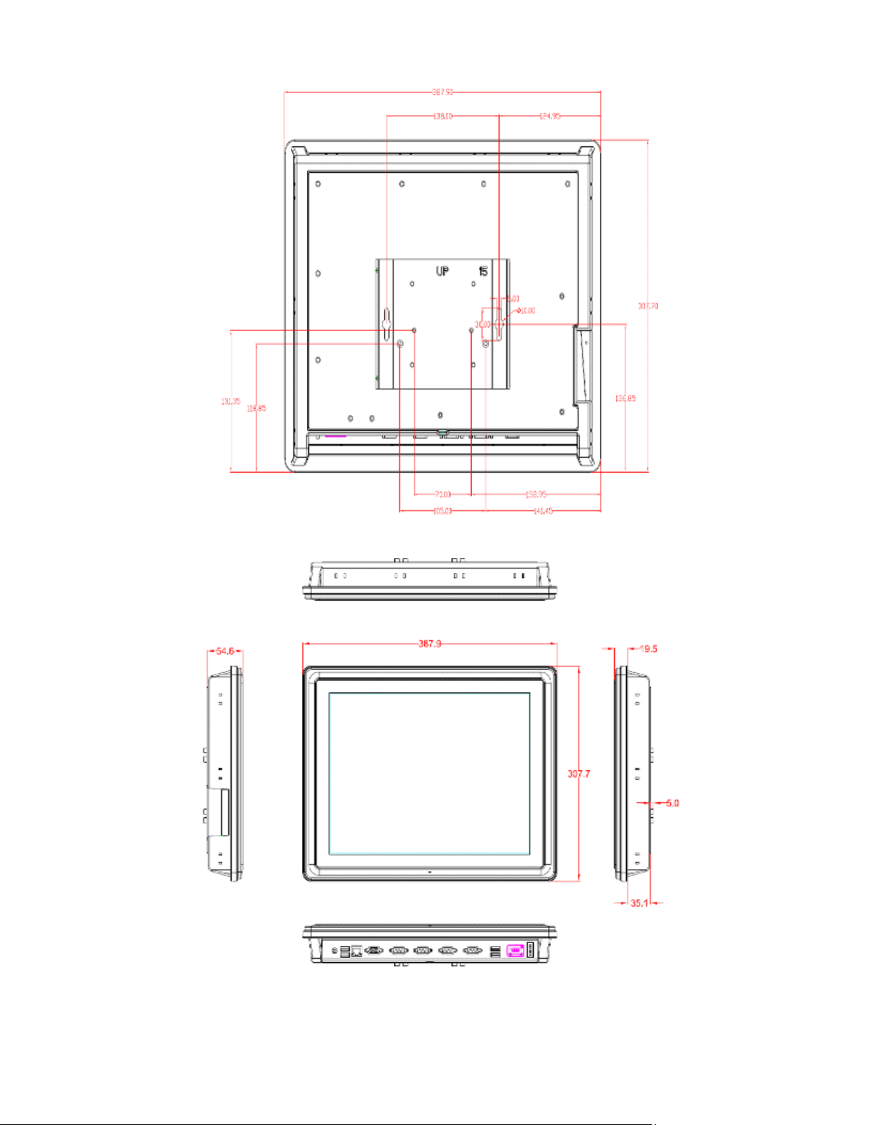
Dimension (Main Body Size)
387.9 x 307.7 x 54.6mm
Operation Temperature
0? to 50?
Relative Humidity
10% to 90% @ 40 , Non-Condensing
Vibration
2.0G, 5 to 500 Hz, 2.0 G random for CF card
Power input
10~30VDC with phoenix power connector
External 60W AC Adapter
— Power Input: 90VAC to 264VAC
— Power Output: 12VDC, Max. 5A
NOTE All s pe ci fic ati ons and i ma ge s ar e subj ec t t o c hange wi thout n otic e.
NOTE If the ope ra tion te mp er atur e i s highe r tha n 3 5? , the wide tempe r atur e
HDD is r e commend ed to be us ed on the dev ic e.
NOTE If the operation temperature is higher than 45 ? , the wide temperature RAM is
recommended to be used on the device.
Page 8
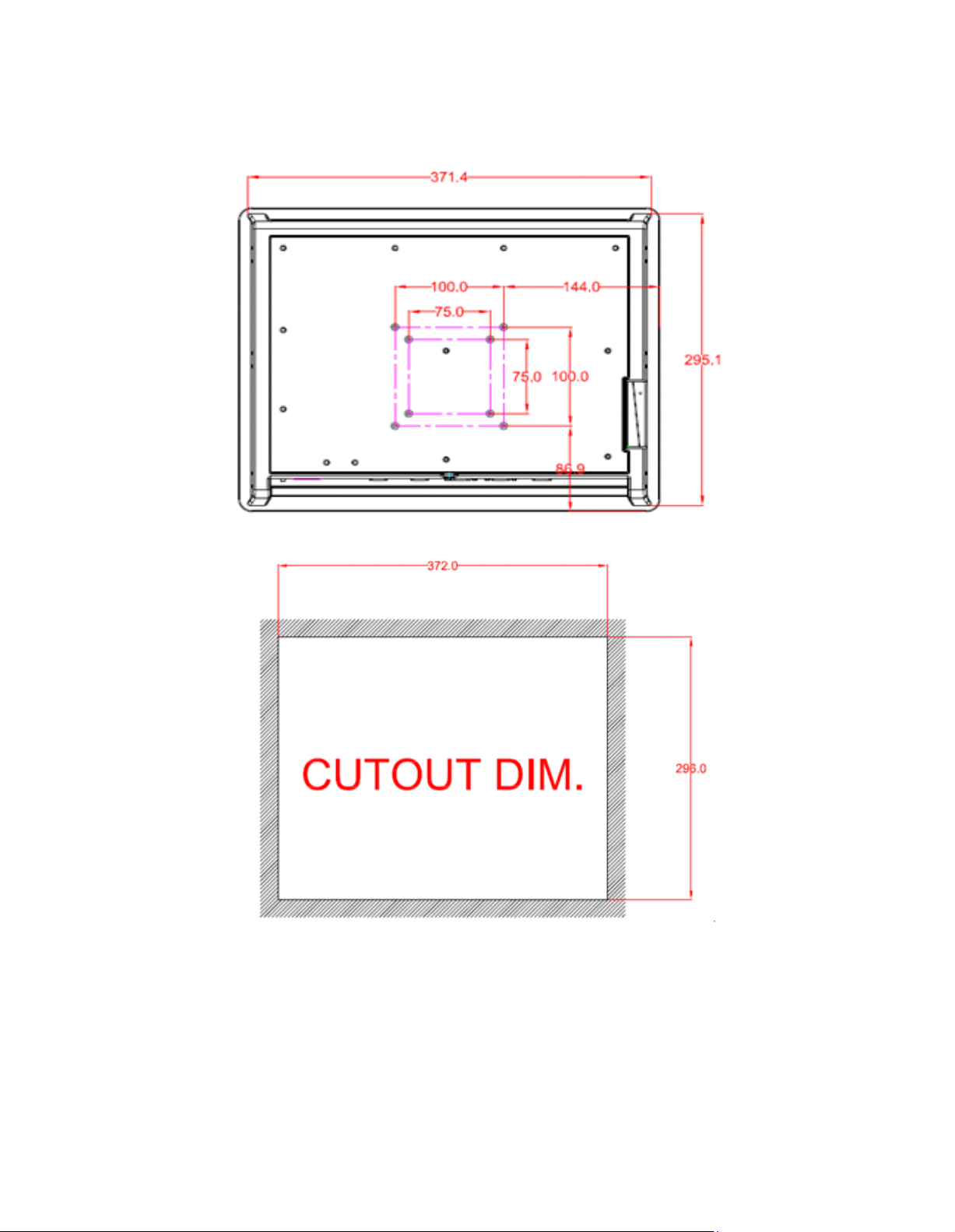
1.3 Dimensions
This di agram sho ws you d imens ions and outli nes of the FPC5 152.
Page 9
Page 10

1.4 I/O Outlets
Please refer to the following illustration for I/O locations of the FPC5152.
No Function
1 POWER SWITCH (ATX)
2.1 Power Input connector (screw type)
2.2 Power Input connector (phoenix type)
3 2xUSB 2.0
4 COM 3(RS-232)
5 VGA
6 COM 1(RS-232/422/485)
7 COM 2(RS-232)
8 2xETHERNET
9 2xUSB2.0
10 AUDIO (LINE-OUT)
Page 11

1.5 Packing List
When you receive the FPC5152, the bundled package should contain the following items:
FPC5152 x 1
Panel Mount Kit x 10
Driver CD x1
Wall-Mount Kit x1
If you cannot find the package or any items are missing, please contact Acnodes distributors
immediately.
Page 12

Chapter 2
Hardware and Installation
The FPC5152 provides rich I/O ports and flexible expansions for you to meet different
demand, for example, CF card. The chapter will show you how to install the hardware. It
includes:
CompactFlash™ Card
Serial Port
Ethernet
Mounting Way
Hard disk
DRAM
Wireless LAN Card
Page 13
h
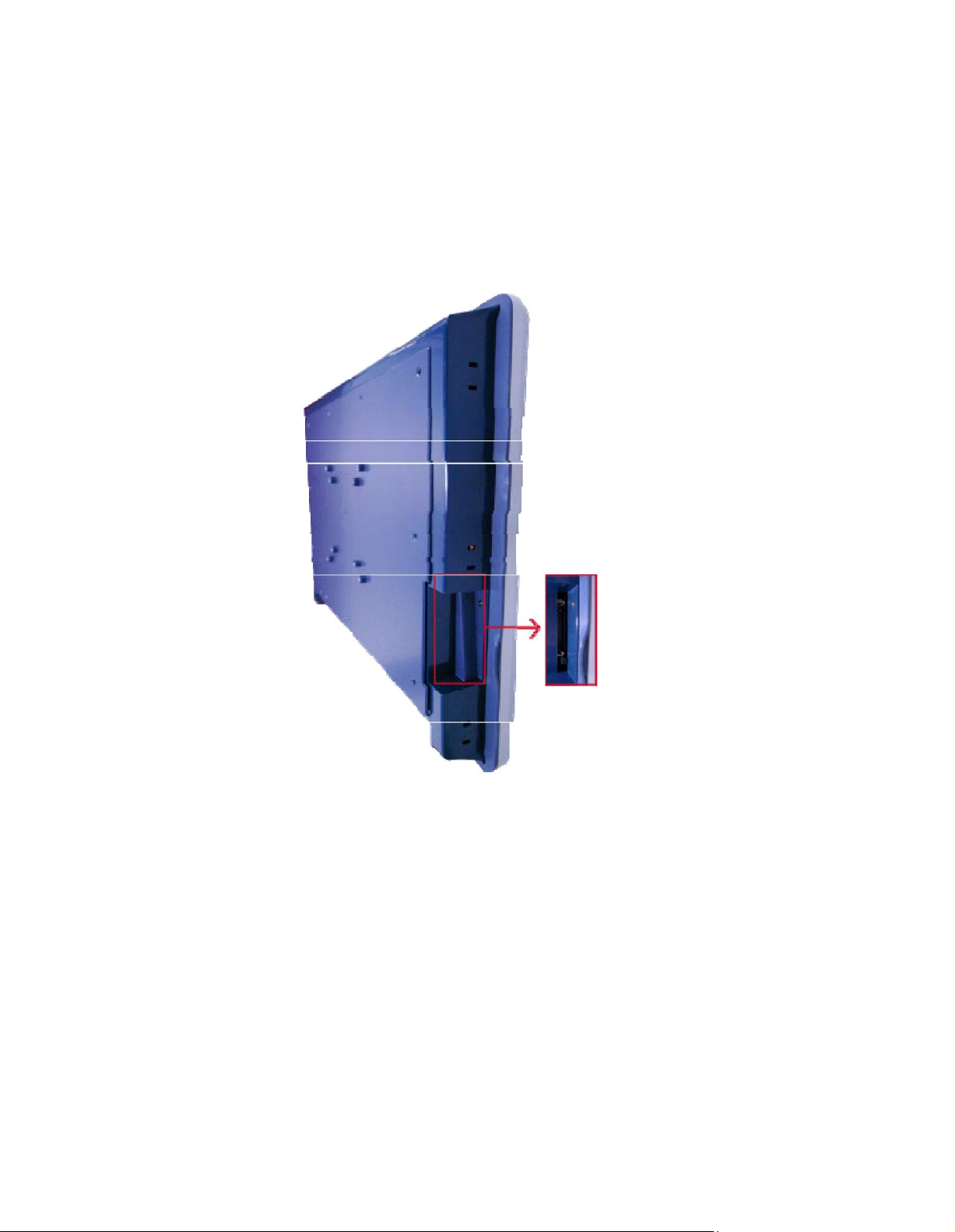
2.1 CF card Installation
The FPC5152 provides one CF slot for users to install CompactFlash™ card. Please refer
to the following instructions for installation:
Step 1 Turn off the system, and unplug the power cord.
Step 2 Remove the cover of CF socket.
Step 3 Locate the CompactFlas
TM
socket, and insert the card into the socket.
Page 14
P in
Signal
Pin
Signal
1
Dat a Ca rrier De tect (DCD)
6
Dat a Se t Re ad y (DSR)
2
Rece ive Da ta (RXD)
7
Req ue st To Se nd (R TS)
3
Tran smit D at a (TXD)
8
Clea r To Se nd (CTS)
4
Dat a Te rmina l R ea dy (DT R)
9
Ring I nd icat or (RI )
5
Gr ou nd (GND)
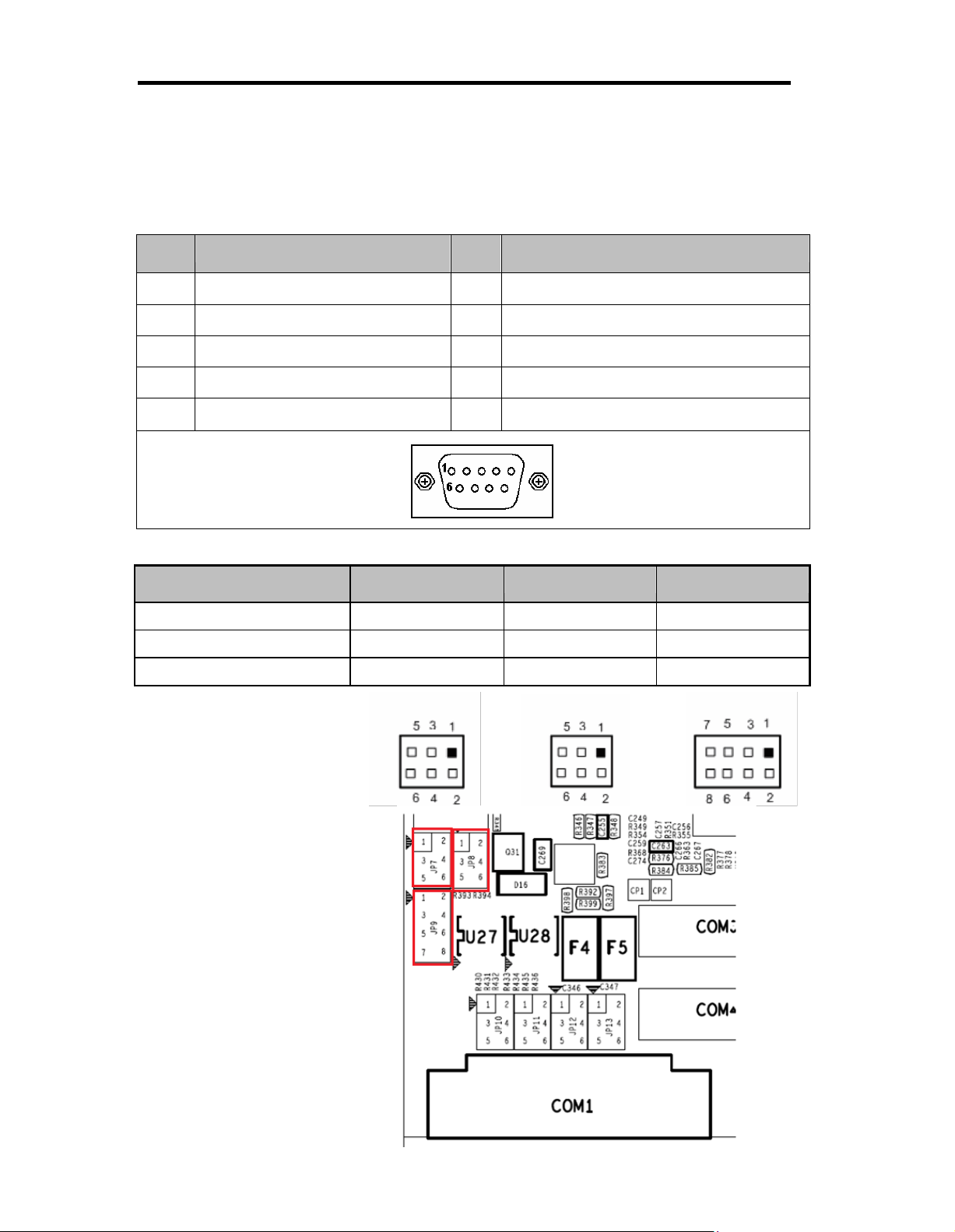
COM 1
JP 7
JP8
JP 9
RS-2 32 (d ef au lt )
3-5, 4-6
3-5, 4-6
1-2
RS-42 2
1-3, 2-4
1-3, 2-4
3-4, 7-8
RS-48 5
1-3, 2-4
1-3, 2-4
5-6, 7-8
2.2 Seria l Ports Interface
The FPC5152 has two onboard serial ports, COM1 (RS-232/ 422/ 485), COM2 (RS-232)
and COM3 (RS-232).
The following table shows you the pin assignments of this connector:
In addition, COM1 can be set for RS-232/422/485 by jumper. The jump setting is listed as below:
Page 15

Signa l
P in
RS- 422
RS- 485
1
TX-
DATA-
2
TX+
DATA+
3
RX+
No connector
4
RX-
No connector
5
No connector
No connector
6
No connector
No connector
7
No connector
No connector
8
No connector
No connector
9
GND
GND
P in
Signa l
1 2 3 4 5 6 7 8
RJ-45
1
TX+ (Data transmission positive
2
TX- (Data transmission negative)
3
Rx+(Data reception positive)
4
RJ45 termination
5
RJ45 termination
6
Rx- (Data reception negative)
7
RJ45 termination
8
RJ45 termination
When COM1 is set to RS-422 or RS-485, the pin assignments are listed below:
2.3 Etherne t
The FPC5152 is equipped with two high performance Plug and Play Ethernet interfaces, full
compliant with IEEE 802.3 standard, and can be connected with a RJ-45 LAN connector.
Please refer to detailed pin assignment list below:
Page 16

2.4 Mountings – Pane l/Wall/Des ktop/VES A
There are several mounting ways for the FPC5152, Panel, Wall, Desktop and VESA
mountings.
2.4.1 Panel Mounting
The FPC5152 is designed for panel mount application. A set of standard m ounting kit are
bundled with the system package that you can use it to mount the FPC5152.
Page 17

2.4.2 Wall-Mounting
The FPC5152 is designed for Wall mounting application. Please refer to the
following steps:
Fix wall mount bracket on the back of the unit.
2.4.3 Desktop-Mounting
The FPC5152 is designed for desktop mounting application. Please refer to the
following steps:
Step 1 Find out the screws as marked on the back side of chassis.
Page 18

Step 2 Assemble the desktop stand to the chassis, and fix the screws.
CAUTION USE RECOMMENDED/SUITABLE MOUNTING APPARATUS TO AVOID RISK OF
INJURY.
Page 19

2.4.4 VESA-ARM Mounting
CAUTION USE RECOMMENDED/SUITABLE MOUNTING APPARATUS TO AVOID RISK OF
INJURY.
Step 1 Find out the screws as marked on the back side of chassis.
Step 2 Assemble the VES A-ARM to the back side of the chassis, and fix the
screws.
Step 3 VESA mounting Installation completed.
Page 20

2.5 HDD Installation
The FPC5152 provides a convenient Hard Disk Drive (HDD) bracket for users to install
2.5” SATA HDD. Please follow the steps:
.
Step 1 Unscrew eight screws to remove the rear chassis.
Page 21

Step 2 Screw the 2.5” HDD to the HDD bracket.
Step 4 Fix the HDD bracket into the system, and plug the data and power cable to
HDD. Installation complete.
Page 22

2.6 DR AM Insta llation
The FPC5152 provides one 204-pin DDR3 SODIMM socket that support system
memory up to 4GB. Please follow steps below to install the memory modules:
Step 1 Open the back cover and find the SODIMM socket.
Step 2. Push down latches on each side of the DIMM socket.
Page 23

FPC 5152
Industrial Fanless Panel PC
Step 3 Install the memory module into the socket and push it firmly down until it is
fully seated. The socket latches are levered upwards and clipped on to the
edges of the DIMM.
14628 Central Ave,
Chin o, CA 91710
tel: 909.597.7588, fax:909.597.1939
© Copyrigh t 2013 Acnodes, Inc.
All rights reserved. Product description and product specifi cations
are subj ect to c han ge with out notic e. For l atest produ ct informati on,
please visit Acnodes’ web site at www.acnodes.c om.
Page 24

2.7 Wireless L AN Card Installation
The FPC5152 provides one Mini card slot for user to install one wireless LAN card. When
installing the wireless LAN card, refer to the following instructions and illustration:
Step 1 Open the back cover and find the WLAN slot.
Step 2 The socket latches are clipped on to the edges of the Mini card.Install
wireless LAN card to the socket.
Page 25

Step 3 Find the built-in Antenna cable.
Step 4 There are two connectors on wireless LAN card. One is MAIN, and the other is
auxiliary. Connect antenna cable to MAIN connector on wireless LAN card.
Page 26

Hot Keys
Description
Left/Right
The Left and Right <Arrow> keys allow you to select a setup screen.
Up/Down
The Up and Down <Arrow> keys allow you to select a setup screen or
sub-screen.
+ Plus/Minus
The Plus and Minus <Arrow> keys allow you to change the field value of a
particular setup item.
Tab
The <Tab> key allo ws you to select setup fields.
F1
The <F1> key allows you to display the general help screen.
F2
The <F2> key allows you to load previous values.
F3
The <F3> key allows you to load optimized defaults.
F4
The <F4> key allows you to save any changes you have made and exit
setup. Press the <F4> key to save your change s.
Esc
The <Esc> key allows you to discard any changes you have made and exit
the setup. Press the <Esc> key to exit the setup without saving your
changes.
Enter
The <Enter> key allows you to display or change the setup option listed for a
particular setup item. The <Enter> key can also allow you to display the
setup sub- screens.
Chapter 3
AMI BIOS Setup Utility
This chapter provides users with detailed description how to set up basic system configuration
through the AMIBIOS8 BIOS setup utility.
3.1 Starting
To enter the setup screens, follow the steps below:
Turn on the computer and press the <Del> key immediately.
After you press the <Delete> key, the main BIOS setup menu displays. You can access the
other setup screens from the main BIOS setup menu, such as the Chipset and Power menus.
3.2 Navigation Ke ys
The BIOS setup/utility uses a key-based navigation system called hot keys. Most of the BIOS
setup utility hot keys can be used at any time during the setup navigation process. These k eys
include <F1>, <F2>, <Enter>, <ESC>, <Arrow> keys, and so on.
Note: Some of the navigation keys differ from one screen to another.
Page 27

3.3 Main Menu
When you first enter the Setup Utility, you will enter the Main setup screen. You can always
return to the Main setup screen by selecting the Main tab. There are two Main Setup options.
They are described in this section. The Main BIOS Setup screen is shown below.
System Date/Time
Use this option to change the system time and date. Highlight System Time or System
Date using the <Arrow> keys. Enter new values through the keyboard. Press the <Tab>
key or the <Arrow> keys to move between fields. The date must be entered in MM/DD/YY
format. The time is entered in HH:MM:SS format.
Page 28

3.4 Adva nced Menu
Launch PXE OpROM
Use this item to enable or disable the boot ROM function of the onboard LAN chip when
the system boots up.
Launch Storage OpROM
This item can enable or disable boot option for legacy mass storage devices with option
ROM.
The Advanced menu also allows users to set configuration of the CPU and other system
devices. You can select any of the items in the left frame of the screen to go to the sub
menus:
ACPI Settings
CPU Configuration
IDE Configuration
USB Configuration
NCT6627UD Superior IO Configuration
NCT6627UD HW Monitor
JMB36X ATA Controller Configuration
For items marked with “”, please press <Enter> for more options.
Page 29

ACPI Settings
You can use this screen to select options for the ACPI Configuration, and change the value
of the selected option. A description of the selected item appears on the right side of the
screen.
ACPI Sleep State
Use this item to select the highest ACPI sleep state the system will enter.
Page 30

CPU Configuration
This screen shows the CPU Configuration, and you can change the value of the selected
option.
Hyper-Threading
Use this item to enable or disable Hyper-Threading Technology, which makes a single
physical processor perform multi-tasking function as two logical ones.
Execute Disable Bit
XD can prevent certain classes of malicious buffer overflow attacks when combine d with a
supporting OS (Windows Server 2003 SP1, Windows XP SP2, SuSE Linux 9.2, RedHat
Enterprise 3 Update 3).
Page 31

IDE Configuration
SATA Controller(s)
The optional settings are: [Disabled]; [Enabled].
Configure SATA as
The optional settings are: [IDE]; [AHCI].
Page 32

USB Configuration
You can use this screen to select options for the USB Configuration, and change the value of
the selected option. A description of the selected item appears on the right side of the screen.
Legacy USB Support
The optional settings are: [Auto]; [Disabled]; [Enabled].
Page 33

NCT6627UD Super IO Configuration
You can use this screen to select optio ns for the Super IO Configuration, and change the value
of the selected option. A description of the selected item appears on the right side of the
screen
Serial Port Configuration
Use this item to set parameters of serial port 0~3
Page 34

PC Health Status
This screen shows the Hardware Health Configuration, and a description of the selected item
appears on the right side of the screen.
Page 35

3.5 Chipset Menu
The Chipset menu allows users to change the advanced chipset settings. You can select any
of the items in the left frame of the screen to go to the sub menus:
Host Bridge
Host Bridge For items marked with “”, please press <Enter> for more options.
South Bridge
South Bridge For items marked with “”, please press <Enter> for more options.
Page 36

Memory Frequency and Timing
This item is for memory frequency and timing settings. Press <Enter> to go to the sub menu.
Page 37

Intel IGD Configuration
You can use this screen to select options for the Intel IGD Configuration, and change the value
of the selected option. A description of the selected item appears on the right side of the
screen.
Press [Enter] to make settings for Intel IGD Configuration:
IGFX-Boot Type
Use this item to set the video device which will be activated during POST.
This has no effect if external graphics presents.
The optional settings are: [Auto]; [CRT]; [DP]; [INT-LVDS];
LCD Panel Type:
The optional settings are: [640 x 480 18bit]; [800 x 600 18bit]; [1024 x 768 18bit]; [1280 x 1024
18bit]; [1366x768 18bit]; [1224x600 18bit]; [1280 x 800 18bit]
Page 38

3.6 Boot Menu
The Boot menu allows users to change boot options of the system.
Boot Settings Configuration
Setup Prompt Timeout
Use this item to set number of seconds to wait for setup activation key.
Bootup NumLock State
Use this item to select the power-on state for the NumLock.. The optional settings are: [On];
[Off].
GateA20 Active
If Upon Request is selected, GA20 can be disabled using BIOS serv ices. If Always is selected,
disabling G20 is not allowed; this option is useful when any RT code is executed above 1MB.
Option ROM Messages
Set displa y mode for option ROM. Configuration options are Force BIOS and Keep Current.
Interrupt 19 Capture
If this item is enabled, this function makes the option ROM to trap Interrupt 19.
Boot Option Priorities
These are settings for boot priority. Specify the boot device priority sequence from the
available de vices.
Page 39

3.7 Security Menu
The Security menu all ows users to change the security settings for the system.
Administrator Password
This item indicates whether an administrator password has been set. If the password has been
installed, Installed displays. If not, Not Installed displays.
User Password
This item indicates whether an user password has been set. If the pass word has been installed,
Installed displays. If not, Not Installed displays.
Page 40

3.8 Save & Exit Menu
The Save & Exit menu allows users to load your system configuration with optimal or fail-safe
default values.
Save Changes and Exit
When you have completed the system configuration changes, select this option to leave Setup
and reboot the computer so the new system configuration parameters can take effect. Select
Save Changes and Exit from the Exit menu and press <Enter>. Select Ok to save changes
and exit.
Discard Changes and Exit
Select this option to quit Setup without making any permanent changes to the system
configuration. Select Discard Changes and Exit from the Exit menu and press <Enter>. Select
Ok to discard changes and exit.
Save Changes and Reset
When you have completed the system configuration changes, select this option to leave Setup
and reboot the computer so the new system configuration parameters can take effect. Select
Save Changes and Reset from the Save & Exit menu and press <Enter>. Select Yes to save
changes and reset.
Discard Changes and Reset
Select this option to quit Setup without making any permanent changes to the system
configuration and reboot the computer. Select Discard Changes and Reset from the Save &
Exit menu and press <Enter>. Select Yes to discard changes and reset.
Save Changes
When you have completed the system configuration changes, select this option to save
changes. Select Save Changes from the Save & Exit menu and press <Enter>. Select yes to
save changes.
Page 41

Discard Changes
Select this option to quit Setup without making any permanent changes to the system
configuration. Select Discard Changes from the Save & Exit menu and press <Enter>. Select
Yes to discard changes.
Restore Defaults
It automatically sets all Setup options to a complete set of default settings when you select this
option. Select Restore Defaults from the Save & Exit m enu and press <Enter>.
Save as User Defaults
Select this option to save system configuration changes done so far as User Defaults. Select
Save as User Defaults from the Save & Exit menu and press <Enter>.
Restore User Defaults
It automatically sets all Setup options to a complete set of User Defaults when you select this
option. Select Restore User Defaults from the Save & Exit menu and press <Enter>.
Boot Override
Select a drive to immediately boot that device regardless of the current boot order.
Page 42

Touch Screen
5-wire Analog Resistive type
Touch Screen Controller
PenMount 6000 USB
Touch Screen Controller IC
Communications
USB Interface
Baud Rate
19200 baud rate fixed
Resolution
1024 x 1024 (10 bit A/D converter inside)
Power Input
5V
Power Consumption
Active: 24.6mA / Idle Mode: 13.4mA
Chapter 4
Drivers Installation
4.1 S ystem
FPC5152 supports Windows 7 32-bit. To facilitate the install ation of system driver,
please carefully read the instructions in this chapter before start installing.
Step 1 Insert Driver CD and select the “\Drivers”.
Step 2 Select all files and follow the installing procedure.
4.2 Touch Scre en
The FPC5152 uses the 5-wire analog resistve. There are the specification and driver
installation which are listed below.
Specification
Page 43

Driver Installation- Windows 7 32-bit
The FPC5152 provides a touch screen driver that users can install it under the operating
system Winodrws 7 32-bit. To facilitate installation of the touc h screen driver, you should read
the instructions in this chapter carefully before you attempt installation.
Step 1 Insert Driver CD and follow the path to select the “\Drivers\Step 5 - Touch”.
Step 2 Follow the installing procedure and press OK.
Click Start menu and select “PenMount Utilities”; and then, a “PenMount Control
Panel” pops out.
Step 3 Select the “Standard Calibrate”
Page 44

Step 4 Calibration:
To adjust the display with touch panel, click “Calibration” and follow the calibrate
point to do calibration; there are five points on screen for calibration.
Step 5 Press OK.
4.3 Embedde d O.S.
The FPC5152 provides the Windows 7 Embedded. The O.S. is supported devices which are
listed below.
WES 7
Here are supported onboard devices:
Onboa rd Mu lti I/O
S ATA HDD
US B
P S2 K eybo ard and m ous e
CRT/LCD dis pla y(D efault 18bits Re solu tion 1024x 768)
10 /1 00/1000 bas e-T Eth ernet
Co mpac t Fla s h
Onboa rd Au dio
Touc h Sc ree n
 Loading...