

Page 1

MCS
User Manual
MCS: Multi-display control solution
14628 Central Ave,
Chin o, CA 91710
tel: 909.597.7588, fax:909.597.1939
Multi-display Control Module Panel
© Copyrigh t 2013 Acnodes, Inc.
All rights re served. Product description and product specifi cations
are subj ect to chan ge without notic e. For latest product inf ormati on,
please visit Acnodes’ we b site at www.acnode s.com.
Page 2

< Part. 1 > Interface
1.1 Connection
Contents
P.1
1.2 Connection Standard
< Part. 2 > Command
2.1 CAN Bus Registry
2.2 Get Address
2.3 Get Name
2.4 Get Power Status
2.5 Get Display Status
2.6 Get Screen Status
2.7 Get PIP Status
2.8 Get Display ID
2.9 Get Display Name
2.10 Get Display ID & Name
2.11 Volume Control
2.12 Mute Control
2.13 Input Source Select
2.14 OSD Button Control
2.15 Infrared Remote Control
2.16 Sound Select Control
2.17 Contrast Control
2.18 Brightness Control
2.19 Auto Adjust Control
2.20 Power Control
2.21 PIP Control
2.22 PIP Source Control
2.23 PIP Swap Control
2.24 PIP Location Control
P.2 - 3
P.4
P.5
P.6
P.7
P.8
P.9
P.10
P.11
P.12
P.13
P.14
P.15
P.16
P.17
P.18
P.19
P.20
P.21
P.22
P.23
P.24
P.25
P.26 - 27
P.28
P.29
Page 3
< Part 1 > Interface
< 1.1 > Connection
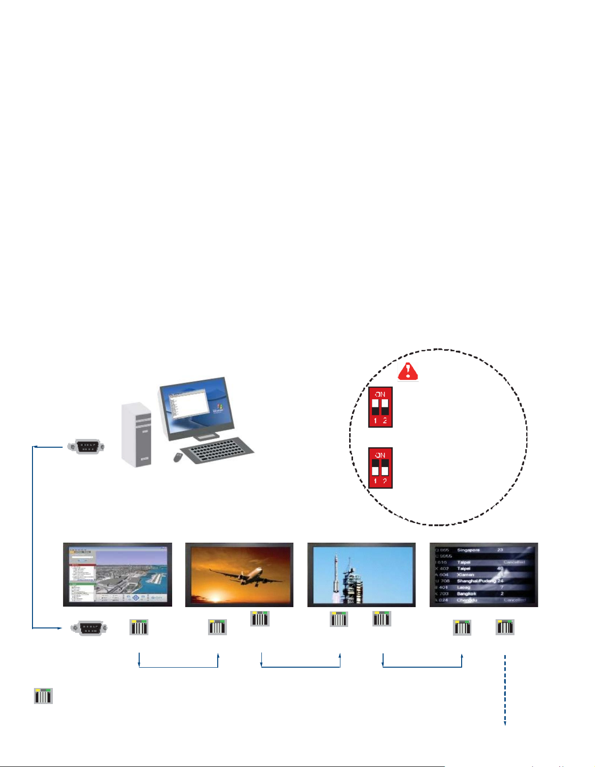
- As shown in Fig. 1-1, first, connect the personal computer ’s RS-232C serial port to the 1st LCD dis
play’s LINK port and then begin to add connections from a LCD display, starting from the OUT port.
- The first & last LCD displays located at both ends of dais y chain connection must be term inated by
setting the pin 1 & 2 of DIP switch ( Set ) to ON position, located next to OUT port. For other daisy
chain LCD display(s), please keep the pin 1 & 2 of DIP switc h at OFF position ( Pin 1 & 2 are
default at OFF position ).
*The new DIP switch setting requires a power cycle of LCD display to take effect.
- The MCS m odule of LCD display will automatically assign an available ID number from 1 to 64 to
each LCD display when connected to the daisy chain, to elim inate LCD displays tr ying to use the
same IDs simultaneously.
15 feet serial cable
( over 15 feet, extender re quired )
Fig. 1- 1 Connecting the PC & LCD Displays
RS-232C
Set switc h
For th e 1st and last display,
push the set switch upward
For other daisy chain displays,
push the set switch downward
RJ-45 jack
LINK OUT
Cat5 / 6
max. 300
IN OUT IN OUT IN OUT
cable
meters
Cat5 / 6 c
max. 300
meters
Daisy chain up to
meter s and 64
displays
able
1,000
Cat5 / 6
max. 300
cable
meters
up to 64 displays
Page 4
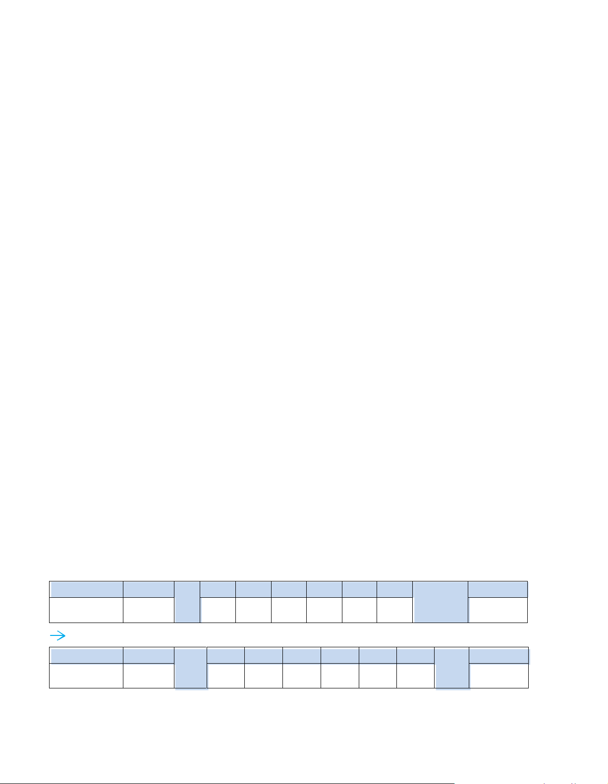
< 1.2 > Connection Standard
Header
Command
ID
Val 1
Val 2
Val 3
Val 4
Val 5
Val 6
Checksum
Footer
0x4D,
0x43,0x06
0 x04
Power
0x00
0x00
0x00
0x00
0x00
0x0D, 0x0A
Header
Command
0x01
Val 1
Val 2
Val 3
Val 4
Val 5
Val 6
0xFA
Footer
0x4D,
0x43,0x06
0 x04
0x01
0x00
0x00
0 x00
0x00
0x00
0x0D, 0x0A
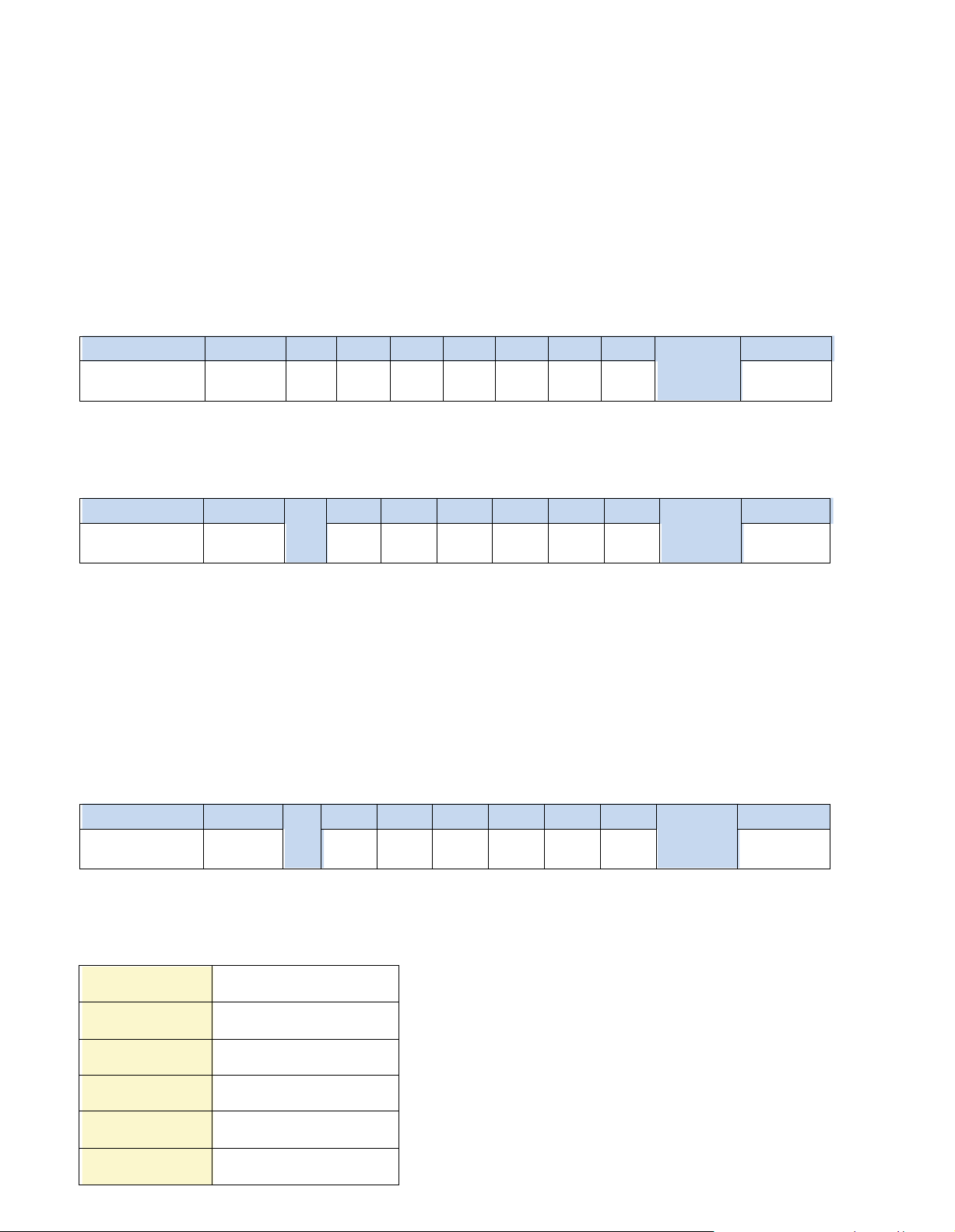
1) Computer to LCD display connection standard
- Conducts bi-direction al communication using serial RS232.
- Use three signal wires of TxD, ( pin 2 ), RxD ( pin 3 ) and GND ( pin 5 ), among the RS232
standard wires, as Fig.
2-1.
- Use DTR ( pin 4 ), RTS ( pin 7 ) for hot-plug detect.
- The distance between the PC computer to LCD display is limited 15m.
2) LCD display to LCD display conn ection standard
3) Command communications
- Conducts bi-direction al communication using CAN bus
- A maxim um of 64 LCD display units can be dais y chained to one CAN bus, up to 1,000 meters.
- The distance between LCD Displays is limited 300 meters via Cat 5/ 6 cable.
The CAN bus requires the MCS module of LCD display registration by sending command < 0x01 >
to add or remove the LCD display(s) from the CAN bus before com mand com munications. Please
refer to page 6 for m ore details.
All communications are conducted in the form of hexadec imal number, and the checksum c alculation
method as below :
Total = Command + ID + Val1 + Val2 + Val3 + Val4 + Val5 + Val6;
Checksum = 256 – Total;
* Unsigned character of Chec ksum, Total=0;
Get Power Status ( e.g. Power ON & ID=1 )
Here, each set functions according to the com mands received and responds with ACK at the same time.
Therefore, the operation of each set s hould be checked after this process.
Page 5
MCS
Port
Color
Activity
IN
Green
Solid LED indicates that the MSC board is powe red on.
No light indica tes the board is powered off.
IN
Orange
Blinkin g L ED indicated that the data is being transmitte d th rough the connection. No
lig ht indicates no data is transmitted
Bit Rate
9600 bps
Data Bits 8 bits
Parity None
Stop Bits 1 bit
Flow Control None
Multi-display Control Module Panel
< 1.2 > Connection Standard
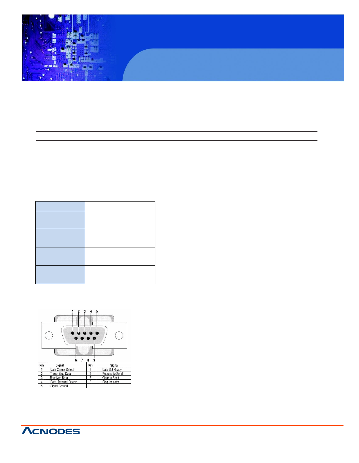
4) The status lights ( LED )
Table 2-1 RS-232 Communication Standards
Fig. 2-1 RS-232 pin out DB-9 pin used for Asynchronous Data
14628 Central Ave,
Chin o, CA 91710
tel: 909.597.7588, fax:909.597.1939
© Copyrigh t 2013 Acnodes, Inc.
All rights re served. Product description and product specifi cations
are subj ect to chan ge without notic e. For latest product inf ormati on,
please visit Acnodes’ we b site at www.acnode s.com.
Page 6
MCS
Multi-display Control Module Panel
© Copyrigh t 2013 Acnodes, Inc.
All rights rese rved. Product des cript ion and product speci ficat ions
are subj ect to chan ge without notic e. For latest product inf ormati on,
please visit Acnodes’ we b site at www.acnode s.com.
14628 Central Ave,
Chin o, CA 91710
tel: 909.597.7588, fax:909.597.1939
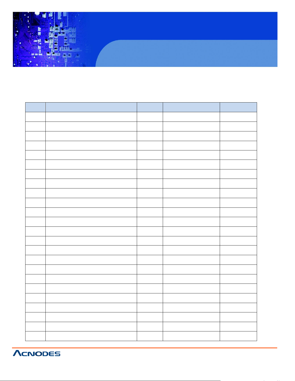
No.
Type of Command
Command
Range of Value ( Decimal )
Wait ACK (ms)
1
CAN Bu s Registry
0x01 --
2,000
2
Get Address
0x02
--
200
3
Get Name
0x03
--
200
4
Get Power Status
0x04
0 ~ 1
200
5
Get Display Status
0x05
--
200
6
Get Screen Sta tus
0x06 --
200
7
Get PIP Sta tus
0x07 --
200
8
Set Display ID
0x15 1 ~ 64
200
9
Set Display Name
0x16 --
200
10
Show Display ID & Name
0x17
5 ~ 255
200
11
Volume Control
0x20
0 ~ 100
200
12
Mute Control
0x21
0 ~ 100
200
13
I nput Source Select
0x22
--
2,000
14
OSD Button Control
0x23
0 ~ 1
200
15
I nfrared Remote Control
0x24 0 ~ 1
200
16
Sound Select Control
0x25 --
200
17
Contrast Control
0x26
0 ~ 100
200
18
Brightness Con trol
0x27
0 ~ 100
200
19
Auto Adjust
0x28 0 5,000
20
Power Control
0x45
0 ~ 1
7,000
21
PIP Control
0x50
--
200
22
PIP Source Select
0x51 --
200
23
Main-PIP Swap Co ntrol
0x52 0
200
24
PIP Locate Control
0x53
--
200
< Part 2 > Command
Page 7
Header
Command
ID
Val 1
Val 2
Val 3
Val 4
Val 5
Val 6
Checksum
Footer
0x06, 0x4D,0x43
0x01
0x00
0x00
0x00
0x00
0x00
0x00
0x00
0x0D, 0x0A
He ader
Command
ID
Val 1
Val 2
Val 3
Val 4
Val 5
Val 6
Checksum
Footer
0x4D, 0x43 ,0x06
0x01
MAC1
MAC2
MAC3
MAC4
0x00
0x00
0x0D, 0x0A
He ader
Co mmand
ID
Val 1
Val 2
Va l 3
Val 4
Val 5
Val 6
Checksum
Footer
0x4D, 0x43 ,0x15
0x01
ERR
0x0 0
0x00
0x00
0x00
0x00
0x0D, 0x0A
0x10
Display contro ller error
0x11
Serial controller error
0x12
Unsupported Command
0x13
Checksum error
0x14
Bad param ete r
0x15
Unknown error
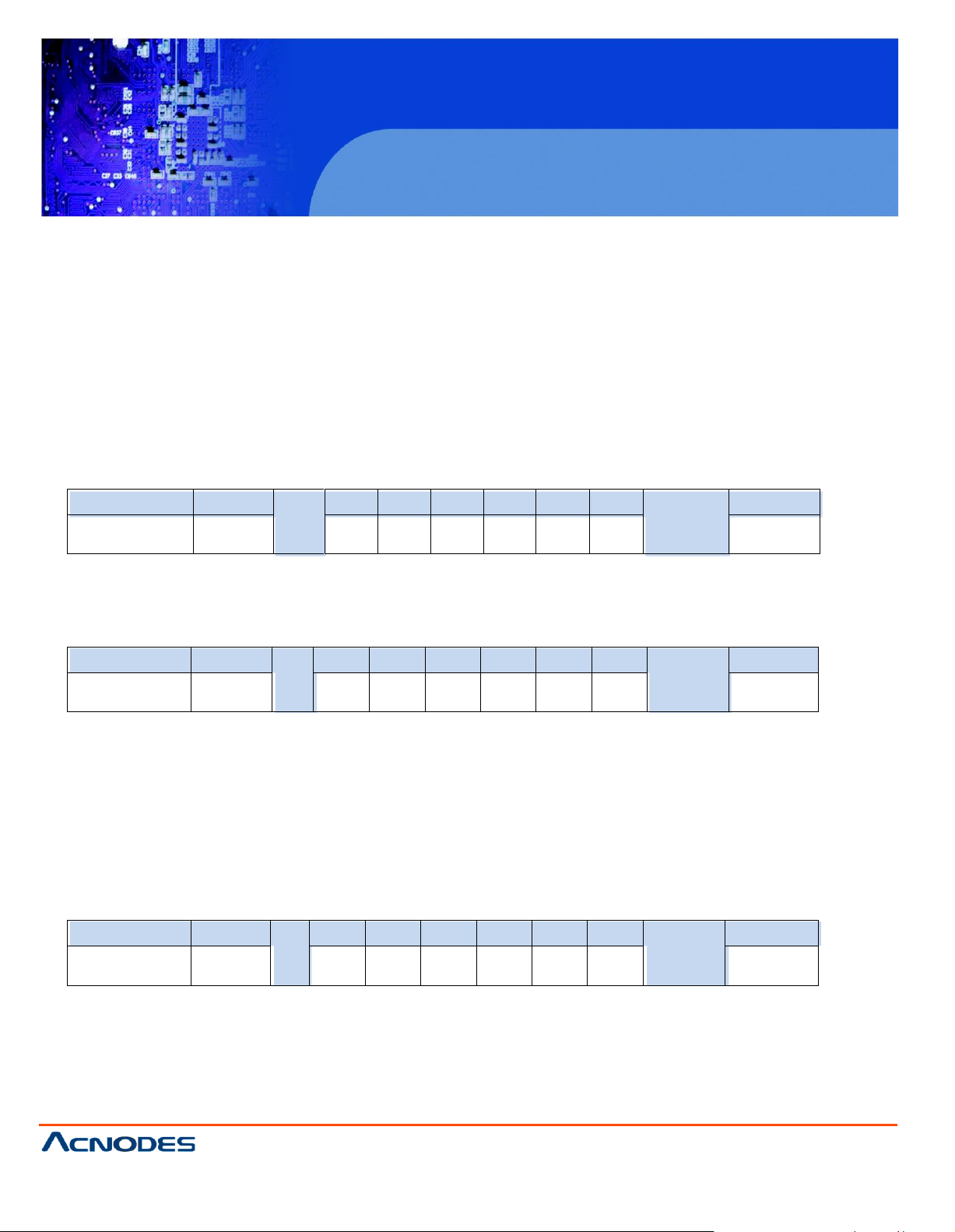
< 2.1 > Detailed Description of Commands
1) CAN Bus Registry
• Function
The computer registers the MCS module of LCD display(s) to CAN bus daisy chain c onnection.
*Registration requires when add or rem ove the LCD displays from the CAN bus connection.
• Register MCS Module(s)
• Ack
MAC1 : The 1st byte of MAC address for the LCD display
MAC2 : The 2nd byte of MAC address for the LCD display
MAC3 : The 3rd byte of MAC address for the LCD display
MAC4 : The 4th byte of MAC address for the LCD display
• Nak
ERR : Error code that shows the type of error that occurred
Page 8
MCS
Multi-display Control Module Panel
© Copyrigh t 2013 Acnodes, Inc.
All rights rese rved. Product des cript ion and product speci ficat ions
are subj ect to chan ge without notic e. For latest product inf ormati on,
please visit Acnodes’ we b site at www.acnode s.com.
14628 Central Ave,
Chin o, CA 91710
tel: 909.597.7588, fax:909.597.1939
Header
Command
ID
Val 1
Val 2
Val 3
Val 4
Val 5
Val 6
Checksum
Footer
0x06, 0x4D,0x43
0x02
0x00
0x00
0x00
0x00
0x00
0x00
0x0D, 0x0A
Header
Comm and
ID
Val 1
Va l 2
Val 3
Val 4
Val 5
Val 6
Checksum
Footer
0x4D, 0x43,0x06
0x02
MAC1
MAC2
MAC3
MAC4
0x00
0x00
0x0D, 0x0A
Header
Command
ID
Val 1
Val 2
Val 3
Val 4
Val 5
Val 6
Checksum
Footer
0x4D, 0x43,0x15
0x02
ERR
0x00
0x00
0x00
0x00
0 x00
0x0D, 0 x0A
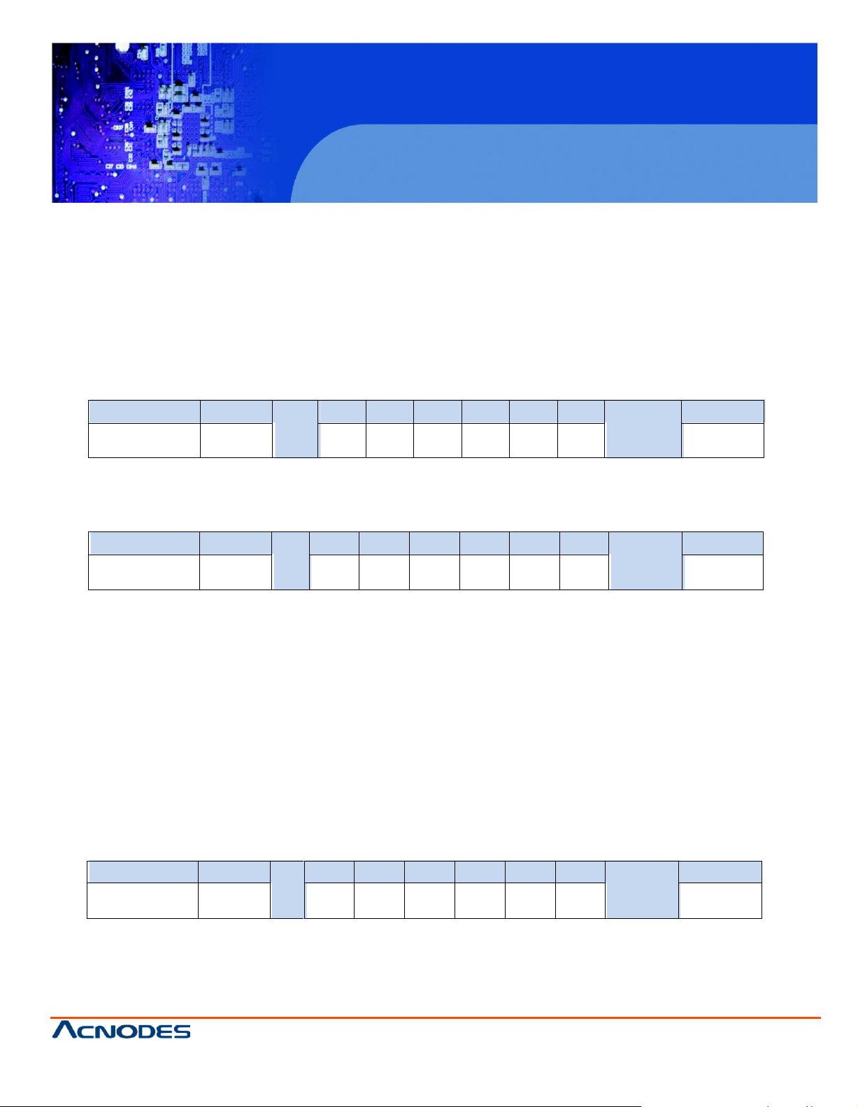
< 2.2 > Get Add ress
• Function
The com puter shows the 32-bit MAC addres s of the LCD display
• Get LCD Display Address
• Ack
• Nak
Page 9
MCS
Multi-display Control Module Panel
© Copyrigh t 2013 Acnodes, Inc.
All rights re served. Product description and product specifi cations
are subj ect to chan ge without notic e. For latest product inf ormati on,
please visit Acnodes’ we b site at www.acnode s.com.
14628 Central Ave,
Chin o, CA 91710
tel: 909.597.7588, fax:909.597.1939
Header
Command
ID
Val 1
Val 2
Val 3
Val 4
Val 5
Val 6
Checksum
Footer
0x06, 0 x4D,0x43
0x03
0x00
0x00
0x00
0x00
0x00
0x00
0x0D, 0 x0A
Header
Command
ID
Val 1
Val 2
Val 3
Val 4
Val 5
Val 6
Checksum
Footer
0x4D, 0x4 3,0x06
0x0 3
Char1
Char 2
Char3
Char4
Char5
Char6
0x0D, 0x0A
He ader
Co mmand
ID
Val 1
Val 2
Va l 3
Val 4
Val 5
Val 6
Checksum
Footer
0x4D, 0x43 ,0x15
0x03
ERR
0x0 0
0x00
0x00
0x00
0x00
0x0D, 0x0A
< 2.3 > Get Name
• Function
The computer shows the name of the LCD display
• Get LCD Display Address
• Ack
MCS
Multi-display Control Module Panel
Char1 : The 1st character of the name
Char2 : The 2nd character of the name
Char3 : The 3rd character of the name
Char4 : The 4th character of the name
Char5 : The 5th character of the name
Char6 : The 6th character of the name
*The default value of the character of the nam e is 0xFF
• Nak
Page 10
MCS
Multi-display Control Module Panel
© Copyrigh t 2013 Acnodes, Inc.
All rights rese rved. Product des cript ion and product speci ficat ions
are subj ect to chan ge without notic e. For latest product inf ormati on,
please visit Acnodes’ we b site at www.acnode s.com.
14628 Central Ave,
Chin o, CA 91710
tel: 909.597.7588, fax:909.597.1939
Header
Command
ID
Val 1
Val 2
Val 3
Val 4
Val 5
Val 6
Checksum
Footer
0x06, 0x4D,0x43
0x04
0x00
0x00
0x00
0x00
0x00
0x00
0x0D, 0x0A
Header
Command
ID
Val 1
Val 2
Val 3
Val 4
Val 5
Val 6
Checksum
Footer
0x4D, 0x43,0x06
0x04
P ower
0x00
0x00
0x00
0x00
0 x00
0x0D, 0 x0A
0x00 Power OFF
0x01 Power ON
Header
Command
ID
Val 1
Val 2
Val 3
Val 4
Val 5
Val 6
Checksum
Footer
0x4D, 0x43,0x15
0x04
ERR
0x00
0x00
0x00
0x00
0 x00
0x0D, 0 x0A
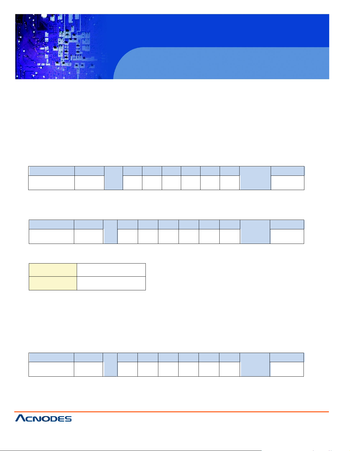
< 2.4 > Get Power Status
• Function
The computer shows the power status of the screen of LCD display
• Get Power Status
• Ack
Power : The power code for the LCD display
• Nak
Page 11

MCS
Multi-display Control Module Panel
© Copyrigh t 2013 Acnodes, Inc.
All rights re served. Product description and product specifi cations
are subj ect to chan ge without notic e. For latest product inf ormati on,
please visit Acnodes’ we b site at www.acnode s.com.
14628 Central Ave,
Chin o, CA 91710
tel: 909.597.7588, fax:909.597.1939
Header
Command
ID
Val 1
Val 2
Val 3
Val 4
Val 5
Val 6
Checksum
Footer
0x06, 0 x4D,0x43
0x05
0x00
0x00
0x00
0x00
0x00
0x00
0x0D, 0 x0A
Header
Command
ID
Val 1
Val 2
Val 3
Val 4
Val 5
Val 6
Check-
sum
Footer
0x4D, 0x4 3,0x06
0x0 5
Vol Mute
Input
OSDB IR
Sound
0x0D, 0x0A
He ader
Co mmand
ID
Val 1
Val 2
Va l 3
Val 4
Val 5
Val 6
Checksum
Footer
0x4D, 0x43 ,0x15
0x05
ERR
0x0 0
0x00
0x00
0x00
0x00
0x0D, 0x0A
< 2.5 > Get Display Status
• Function
The computer shows the current s etting of the LCD display
• Get LCD Display Address
• Ack
Vol : The volume value of the LCD display ( 1~100 )
Mute : The mute code for the LCD display
Input : The input source code for the LCD display
OSDB : The OSD button control code for the LCD display
IR : The infrared remote control code for the LCD display
Sound : The sound select code for the LCD display
• Nak
Page 12

MCS
Multi-display Control Module Panel
© Copyrigh t 2013 Acnodes, Inc.
All rights rese rved. Product des cript ion and product speci ficat ions
are subj ect to chan ge without notic e. For latest product inf ormati on,
please visit Acnodes’ we b site at www.acnode s.com.
14628 Central Ave,
Chin o, CA 91710
tel: 909.597.7588, fax:909.597.1939
Header
Command
ID
Val 1
Val 2
Val 3
Val 4
Val 5
Val 6
Che cksum
Footer
0x06, 0x4D,0x43
0x0 6
0x00
0x00
0x00
0x00
0x00
0x00
0x0D, 0x0A
Header
Command
ID
Val 1
Val 2
Val 3
Val 4
Val 5
Val 6
Checksum
Foo ter
0x4 D, 0 x43,0x06
0x06
Ctrast
Br ight
0x00
0x00
0x00
0x00
0x0D, 0x0A
Header
Command
ID
Val 1
Val 2
Val 3
Val 4
Val 5
Val 6
Checksum
Footer
0x4D, 0x43,0x15
0x0 6
ERR
0x00
0x00
0 x00
0x00
0x00
0x0D, 0 x0A
< 2.6 > Get Screen Status
• Function
The computer shows the current screen setting of the LCD display
• Get Sc reen Status
• Ack
Ctrast : The contrast value of the display
Bright : The brightness value of the display
• Nak
Page 13

MCS
Multi-display Control Module Panel
© Copyrigh t 2013 Acnodes, Inc.
All rights re served. Product description and product specifi cations
are subj ect to chan ge without notic e. For latest product inf ormati on,
please visit Acnodes’ we b site at www.acnode s.com.
14628 Central Ave,
Chin o, CA 91710
tel: 909.597.7588, fax:909.597.1939
Header
Command
ID
Val 1
Val 2
Val 3
Val 4
Val 5
Val 6
Checksum
Footer
0x06, 0 x4D,0x43
0x07
0x00
0x00
0x00
0x00
0x00
0x00
0x0D, 0 x0A
Header
Command
ID
Val 1
Val 2
Val 3
Val 4
Val 5
Val 6
Che cksum
Footer
0x4D, 0x4 3,0x06
0x07
PIP
P.Sour
P. Loc
0x00
0x00
0x00
0 x0D, 0x0A
He ader
Co mmand
ID
Val 1
Val 2
Va l 3
Val 4
Val 5
Val 6
Checksum
Footer
0x4D, 0x43 ,0x15
0x07
ERR
0x0 0
0x00
0x00
0x00
0x00
0x0D, 0x0A
< 2.7 > Get PIP Status
• Function
The computer shows the PIP setting of the LCD display
The PIP function may or not be av ailable on a particular LCD display depending on the model selected
• Get PIP Status
• Ack
PIP : The PIP status value code for the display
P.Sour : The PIP source code for the display
P.Loc : The PIP location code for the display
• Nak
Page 14

MCS
Multi-display Control Module Panel
© Copyrigh t 2013 Acnodes, Inc.
All rights rese rved. Product des cript ion and product speci ficat ions
are subj ect to chan ge without notic e. For latest product inf ormati on,
please visit Acnodes’ we b site at www.acnode s.com.
14628 Central Ave,
Chin o, CA 91710
tel: 909.597.7588, fax:909.597.1939
Header
Command
ID
Val 1
Val 2
Val 3
Val 4
Va l 5
Val 6
Checksum
Footer
0x06, 0x4D,0x43
0x1 5
NewID
0x00
0 x00
0x00
0x00
0x00
0x0D, 0x0A
Header
Command
ID
Val 1
Val 2
Val 3
Val 4
Val 5
Val 6
Checksum
Foo ter
0x4 D, 0 x43,0x06
0x15
NewID
0x00
0 x00
0x00
0x00
0x00
0x0D, 0x0A
Header
Command
ID
Val 1
Val 2
Val 3
Val 4
Val 5
Val 6
Checksum
Footer
0x4D, 0x43,0x15
0x1 5
ERR
0x00
0x00
0 x00
0x00
0x00
0x0D, 0 x0A
< 2.8 > Set Display ID
• Function
The computer changes the LCD display ID num ber.
• Set Dis play ID number
NewID : Changes the LCD dis play’s ID to New ID number (1~64).
*The new ID number will be treated as bad parameter, if the num ber is 0, 65 ~ 255 or the
new ID number already occupied by other LCD display.
• Ack
• Nak
Page 15

MCS
Multi-display Control Module Panel
© Copyrigh t 2013 Acnodes, Inc.
All rights re served. Product description and product specifi cations
are subj ect to chan ge without notic e. For latest product inf ormati on,
please visit Acnodes’ we b site at www.acnode s.com.
14628 Central Ave,
Chin o, CA 91710
tel: 909.597.7588, fax:909.597.1939
Head er
Command
ID
Val 1
Val 2
Val 3
Val 4
Val 5
Val 6
Checksum
Footer
0x06, 0x4D,0x43
0x16
Char1
Char2
Char3
Char 4
Char 5
Char6
0x0D, 0x0 A
Header
Command
ID
Val 1
Val 2
Val 3
Val 4
Val 5
Val 6
Che cksum
Footer
0x4D, 0x43,0x06
0x16
Char 1
Char2
Char3
Char4
Char5
Char 6
0x0D, 0 x0A
Heade r
Command
ID
Val 1
Val 2
Val 3
Val 4
Val 5
Val 6
Checksum
Foo ter
0x4D, 0x43,0x15
0x16
ERR
0x00
0x00
0x00
0x00
0x00
0x0D, 0x0A
< 2.9 > Set Display Name
• Function
The computer sets the name of the LCD display.
• Set Display Name
Char1 : The 1st character of the name
Char2 : The 2nd character of the name
Char3 : The 3rd character of the name
Char4 : The 4th character of the name
Char5 : The 5th character of the name
Char6 : The 6th character of the name
*Character of the nam e c an allow [ a~z ],[ A~Z] , [ 0-9 ] & space character.
• Ack
• Nak
Page 16

MCS
Multi-display Control Module Panel
© Copyrigh t 2013 Acnodes, Inc.
All rights rese rved. Product des cript ion and product speci ficat ions
are subj ect to chan ge without notic e. For latest product inf ormati on,
please visit Acnodes’ we b site at www.acnode s.com.
14628 Central Ave,
Chin o, CA 91710
tel: 909.597.7588, fax:909.597.1939
Header
Command
ID
Val 1
Val 2
Val 3
Val 4
Val 5
Va l 6
Checksum
Footer
0x06, 0x4D,0x43
0x17
Time
0x 00
0x00
0x00
0x00
0x00
0x0D, 0x0A
Header
Command
ID
Val 1
Val 2
Val 3
Val 4
Val 5
Val 6
Checksum
Foo ter
0x4D, 0x43,0x06
0x17
Time
0x00
0x00
0x00
0x00
0x00
0x0D, 0x0A
Header
Command
ID
Val 1
Val 2
Val 3
Val 4
Val 5
Val 6
Checksum
Footer
0x4D, 0x43,0x15
0x17
ERR
0x00
0x00
0x00
0x00
0 x00
0x0D, 0 x0A
< 2.10 > Show Display ID & Name
• Function
The LCD Display shows the ID number & name on the screen
• Show Display ID and Name
Tim e : The second value for the s creen shows the display ID no. & name ( 5~255 )
• Ack
• Nak
Page 17

MCS
Multi-display Control Module Panel
© Copyrigh t 2013 Acnodes, Inc.
All rights re served. Product description and product specifi cations
are subj ect to chan ge without notic e. For latest product inf ormati on,
please visit Acnodes’ we b site at www.acnode s.com.
14628 Central Ave,
Chin o, CA 91710
tel: 909.597.7588, fax:909.597.1939
Head er
Command
ID
Val 1
Val 2
Val 3
Val 4
Val 5
Val 6
Checksum
Footer
0x06, 0x4D,0x43
0x20
Vol
0x00
0x00
0x00
0x00
0x00
0x0D, 0x0 A
Header
Command
ID
Val 1
Val 2
Val 3
Val 4
Val 5
Val 6
Che cksum
Footer
0x4D, 0x43,0x06
0x20
Vol
0x0 0
0x00
0x00
0x00
0 x00
0x0D, 0 x0A
Heade r
Command
ID
Val 1
Val 2
Val 3
Val 4
Val 5
Val 6
Checksum
Foo ter
0x4D, 0x43,0x15
0x20
ERR
0x00
0x00
0x00
0x00
0x00
0x0D, 0x0A
< 2.11 > Volume Control
• Function
The computer change s the volume level of the LCD display
The audio function may or not be available on a partic ular LCD display depending on the model selected
• Set Volum e
Vol : The volume level value code of the LCD display (0~100)
• Ack
• Nak
Page 18

MCS
Multi-display Control Module Panel
© Copyrigh t 2013 Acnodes, Inc.
All rights rese rved. Product des cript ion and product speci ficat ions
are subj ect to chan ge without notic e. For latest product inf ormati on,
please visit Acnodes’ we b site at www.acnode s.com.
14628 Central Ave,
Chin o, CA 91710
tel: 909.597.7588, fax:909.597.1939
Header
Command
ID
Val 1
Val 2
Val 3
Val 4
Val 5
Val 6
Checksum
Footer
0x06, 0x4D,0x43
0x21
Mute
0x00
0x00
0x00
0x00
0x00
0x0D, 0x0A
0x00 Mute OFF
0x01 Mute ON
Header
Command
ID
Val 1
Val 2
Val 3
Val 4
Val 5
Val 6
Checksum
Footer
0x4D, 0x43,0x06
0x21
Mute
0x00
0x00
0x00
0x00
0 x00
0x0D, 0 x0A
Header
Command
ID
Val 1
Val 2
Val 3
Val 4
Val 5
Val 6
Checksum
Footer
0x4D, 0x43,0x15
0x21
ERR
0x00
0x00
0x00
0x00
0 x00
0x0D, 0 x0A
< 2.12 > Mute Control
• Function
The computer turns the mute ON or OFF of the LCD display
The audio function may or not be available on a particular LCD display depending on the model selected
• Set Mute Control
Mute : The mute code for the LCD display
• Ack
• Nak
Page 19

Header
Command
ID
Val 1
Val 2
Val 3
Val 4
Val 5
Val 6
Checksum
Footer
0x06, 0x4D,0x43
0x22
Input
0x00
0x00
0x00
0x00
0x00
0x0D, 0x0A
0x10 V GA
0x11 S-Vide o
0x12 Composite
0x13 DVI-D
0x14 HDMI
0x15 S DI
0x16 YPbPr
0x17 TV
Header
Command
ID
Val 1
Val 2
Val 3
Val 4
Val 5
Val 6
Checksum
Footer
0x4D, 0x43,0x06
0x22
Input
0x00
0x00
0x00
0x00
0 x00
0x0D, 0 x0A
Header
Command
ID
Val 1
Val 2
Val 3
Val 4
Val 5
Val 6
Checksum
Footer
0x4D, 0x43,0x15
0x22
ERR
0x00
0x00
0x00
0x00
0 x00
0x0D, 0 x0A
< 2.13 > Input Source Select
• Function
The computer changes the input source of the LCD display
Some of inputs may or not be availab le on a particular LCD display depending on the model selected
• Set Input Source
Input : The input source code for the LCD display
• Ack
• Nak
Page 20

MCS
Multi-display Control Module Panel
© Copyrigh t 2013 Acnodes, Inc.
All rights rese rved. Product des cript ion and product speci ficat ions
are subj ect to chan ge without notic e. For latest product inf ormati on,
please visit Acnodes’ we b site at www.acnode s.com.
14628 Central Ave,
Chin o, CA 91710
tel: 909.597.7588, fax:909.597.1939
Header
Command
ID
Val 1
Val 2
Val 3
Val 4
Val 5
Val 6
Checksum
Footer
0x06, 0x4D,0x43
0x23
OSDB
0x00
0x00
0x00
0x00
0x00
0x0D, 0x0A
0x00 OFF
0x01 ON
Header
Command
ID
Val 1
Val 2
Val 3
Val 4
Val 5
Val 6
Checksum
Footer
0x4D, 0x43,0x06
0x23
OSDB
0x00
0x00
0x00
0x00
0 x00
0x0D, 0 x0A
Header
Command
ID
Val 1
Val 2
Val 3
Val 4
Val 5
Val 6
Checksum
Footer
0x4D, 0x43,0x15
0x23
ERR
0x00
0x00
0x00
0x00
0 x00
0x0D, 0 x0A
< 2.14 > OSD Button Control
• Function
The computer switches the OSD button function ON /OFF
• Set OSD Button
OSDB : The OSD mem brane button control code for the LCD display
• Ack
• Nak
Page 21

MCS
Multi-display Control Module Panel
© Copyrigh t 2013 Acnodes, Inc.
All rights re served. Product description and product specifi cations
are subj ect to chan ge without notic e. For latest product inf ormati on,
please visit Acnodes’ we b site at www.acnode s.com.
14628 Central Ave,
Chin o, CA 91710
tel: 909.597.7588, fax:909.597.1939
Header
Command
ID
Val 1
Val 2
Val 3
Val 4
Val 5
Val 6
Checksum
Footer
0x06, 0 x4D,0x43
0x24
IR
0x00
0x00
0x00
0x00
0x00
0x0D, 0 x0A
0x00
Remote Disable
0x01
Remote Enable
Header
Comm and
ID
Val 1
Val 2
Va l 3
Val 4
Val 5
Val 6
Checksum
Footer
0x4D, 0x4 3,0x06
0x24
IR
0x0 0
0x00
0x00
0x00
0x00
0x0D, 0x0A
Header
Comm and
ID
Val 1
Val 2
Va l 3
Val 4
Val 5
Val 6
Checksum
Footer
0x4D, 0x4 3,0x15
0x24
ERR
0x0 0
0x00
0x00
0x00
0x00
0x0D, 0x0A
< 2.15 > Infrared Remote Control
• Function
The com puter enables and disables the infrared reception feature of the LCD display
• Set Infrared Remote
IR : Reception enable / disable code for the LCD display infrared remote control
• Ack
• Nak
Page 22

MCS
Multi-display Control Module Panel
© Copyrigh t 2013 Acnodes, Inc.
All rights rese rved. Product des cript ion and product speci ficat ions
are subj ect to chan ge without notic e. For latest product inf ormati on,
please visit Acnodes’ we b site at www.acnode s.com.
14628 Central Ave,
Chin o, CA 91710
tel: 909.597.7588, fax:909.597.1939
Header
Command
ID
Val 1
Val 2
Val 3
Val 4
Val 5
Val 6
Checksum
Footer
0x0 6, 0x4D,0x43
0x2 5
S.S el
0x00
0 x00
0x00
0x00
0x00
0x0D, 0x0A
0x01 Main
0x02 P IP
He ader
Co mmand
ID
Val 1
Val 2
Va l 3
Val 4
Val 5
Val 6
Checksum
Footer
0x4D, 0x43 ,0x06
0x25
S.Sel
0x0 0
0x00
0x00
0x00
0x00
0x0D, 0x0A
He ader
Co mmand
ID
Val 1
Val 2
Va l 3
Val 4
Val 5
Val 6
Checksum
Footer
0x4D, 0x43 ,0x15
0x25
ERR
0x0 0
0x00
0x00
0x00
0x00
0x0D, 0x0A
< 2.16 > Sound Select Control
• Function
The computer switches the sound setting of the LCD display
The PIP function may or not be available on a particular LCD dis play depending on the model selected
• Set Sound
S.Sel : The sound s elec t code for the LCD display
• Ack
• Nak
Page 23

MCS
Multi-display Control Module Panel
© Copyrigh t 2013 Acnodes, Inc.
All rights re served. Product description and product specifi cations
are subj ect to chan ge without notic e. For latest product inf ormati on,
please visit Acnodes’ we b site at www.acnode s.com.
14628 Central Ave,
Chin o, CA 91710
tel: 909.597.7588, fax:909.597.1939
Header
Command
ID
Val 1
Val 2
Val 3
Val 4
Val 5
Val 6
Checksum
Footer
0x06, 0x4D,0x43
0x2 6
ContV
0x00
0x0 0
0x00
0x00
0x00
0x0D, 0x0A
Header
Comm and
ID
Val 1
Val 2
Va l 3
Val 4
Val 5
Val 6
Checksum
Footer
0x4D, 0x4 3,0x06
0x26
ContV
0x0 0
0x00
0x00
0x00
0x00
0x0D, 0x0A
Header
Comm and
ID
Val 1
Val 2
Va l 3
Val 4
Val 5
Val 6
Checksum
Footer
0x4D, 0x4 3,0x15
0x26
ERR
0x0 0
0x00
0x00
0x00
0x00
0x0D, 0x0A
< 2.17 > Contrast Control
• Function
The com puter adjusts the c ontrast of the LCD display
• Set Contrast
ContV : The contras t value code for the LCD display ( 0~ 100 )
• Ack
• Nak
Page 24

MCS
Multi-display Control Module Panel
© Copyrigh t 2013 Acnodes, Inc.
All rights rese rved. Product des cript ion and product speci ficat ions
are subj ect to chan ge without notic e. For latest product inf ormati on,
please visit Acnodes’ we b site at www.acnode s.com.
14628 Central Ave,
Chin o, CA 91710
tel: 909.597.7588, fax:909.597.1939
Header
Command
ID
Val 1
Val 2
Val 3
Val 4
Val 5
Val 6
Checksum
Footer
0x06, 0x4D,0x43
0x27
Bright
0x00
0 x00
0x00
0x0 0
0x00
0x0D, 0x0A
Header
Command
ID
Val 1
Val 2
Val 3
Val 4
Val 5
Val 6
Checksum
Footer
0x4D, 0x43,0x06
0x27
Bright
0x00
0x00
0x00
0x00
0 x00
0x0D, 0 x0A
Header
Command
ID
Val 1
Val 2
Val 3
Val 4
Val 5
Val 6
Checksum
Footer
0x4D, 0x43,0x15
0x27
ERR
0x00
0x00
0x00
0x00
0 x00
0x0D, 0 x0A
< 2.18 > Brightness Control
• Function
The computer adjusts the brightness of the LCD display
• Set Brightness
Bright : The brightness value code for the LCD dis play ( 0~ 100 )
• Ack
• Nak
Page 25

MCS
Multi-display Control Module Panel
© Copyrigh t 2013 Acnodes, Inc.
All rights re served. Product description and product specifi cations
are subj ect to chan ge without notic e. For latest product inf ormati on,
please visit Acnodes’ we b site at www.acnode s.com.
14628 Central Ave,
Chin o, CA 91710
tel: 909.597.7588, fax:909.597.1939
Header
Command
ID
Val 1
Val 2
Val 3
Val 4
Val 5
Val 6
Checksum
Footer
0x06, 0 x4D,0x43
0x28
A.Adj
0x00
0x00
0x00
0x00
0x00
0x0D, 0 x0A
Header
Comm and
ID
Val 1
Val 2
Va l 3
Val 4
Val 5
Val 6
Checksum
Footer
0x4D, 0x4 3,0x06
0x28
A.Adj
0x0 0
0x00
0x00
0x00
0x00
0x0D, 0x0A
Header
Comm and
ID
Val 1
Val 2
Va l 3
Val 4
Val 5
Val 6
Checksum
Footer
0x4D, 0x4 3,0x15
0x28
ERR
0x0 0
0x00
0x00
0x00
0x00
0x0D, 0x0A
< 2.19 > Auto Adjust Control
• Function
Auto adjusts the VGA picture position on the screen
Available only when input sour ce is VGA
• Set Auto A dust
A.Adj : The auto adjust code for the LCD display ( 0x00 )
• Ack
• Nak
Page 26

MCS
Multi-display Control Module Panel
© Copyrigh t 2013 Acnodes, Inc.
All rights rese rved. Product des cript ion and product speci ficat ions
are subj ect to chan ge without notic e. For latest product inf ormati on,
please visit Acnodes’ we b site at www.acnode s.com.
14628 Central Ave,
Chin o, CA 91710
tel: 909.597.7588, fax:909.597.1939
Header
Command
ID
Val 1
Val 2
Val 3
Val 4
Val 5
Va l 6
Checksum
Footer
0x0 6, 0x4D,0x43
0x45
Power
0x00
0x00
0x00
0x00
0x00
0x0D, 0 x0A
0x00
Power OFF
0x01 Power ON
He ader
Co mmand
ID
Val 1
Val 2
Va l 3
Val 4
Val 5
Val 6
Checksum
Footer
0x4D, 0x43 ,0x06
0x45
Power
0x0 0
0x00
0x00
0x00
0x00
0x0D, 0x0A
He ader
Co mmand
ID
Val 1
Val 2
Va l 3
Val 4
Val 5
Val 6
Checksum
Footer
0x4D, 0x43 ,0x15
0x45
ERR
0x0 0
0x00
0x00
0x00
0x00
0x0D, 0x0A
< 2.20 > Power Control
• Function
The computer switches the power for the screen of LCD display
• Set Power
Power : The power code for the s creen of LCD display
• Ack
• Nak
Page 27

Head er
Command
ID
Val 1
Val 2
Val 3
Val 4
Val 5
Val 6
Checksum
Foo ter
0x06, 0x4D,0x43
0x50
P IP
0x00
0x00
0x00
0x00
0x00
0x0D, 0x0 A
0x10 PIP OFF
0x11 Small
0x12 Large
0x13 S ide by side
Header
Command
ID
Val 1
Val 2
Val 3
Val 4
Val 5
Val 6
Checksum
Footer
0x4D, 0x43,0x06
0x50
PIP
0x00
0x00
0x00
0x00
0 x00
0x0D, 0 x0A
Header
Command
ID
Val 1
Val 2
Val 3
Val 4
Val 5
Val 6
Checksum
Footer
0x4D, 0x43,0x15
0x50
ERR
0x00
0x00
0x00
0x00
0 x00
0x0D, 0 x0A
< 2.21 > PIP Control
• Function
The computer turns the PIP function of the LCD display.
The PIP function may or not be available on a particular LCD display depen ding on the m odel selected
• Set PIP Control
PIP : The PIP function code for the LCD display
• Ack
• Nak
Page 28

Header
Comm and
ID
Val 1
Val 2
Val 3
Val 4
Va l 5
Val 6
Checksum
Footer
0x06, 0 x4D,0x43
0x51
P.S our
0x00
0x00
0x00
0x00
0x00
0x0D, 0x0A
0x10 VGA
0x11 S-Video
0x12 Composite
0x13 DVI-D
0x14 HDMI
0x15 SDI
0x16 YPbP r
0x17 TV
Heade r
Comm and
ID
Val 1
Val 2
Val 3
Val 4
Val 5
Val 6
Check-
sum
Footer
0x4D, 0x43,0x06
0x51
P.Sour
0x00
0x00
0x00
0x00
0x00
0x0D, 0x0A
Heade r
Comm and
ID
Val 1
Val 2
Va l 3
Val 4
Val 5
Val 6
Checksum
Footer
0x4D, 0x43,0x15
0x51
ERR
0x0 0
0x00
0x00
0x00
0x00
0x0D, 0x0A
< 2.22 > PIP Source Control
• Function
The computer adjusts the PIP source of the LCD display
The PIP function may or not be available on a particular LCD display depending on the model selected
Available only when PIP function is ON
• Set PIP Source
P.Sour : The PIP source code for the LCD display
• Ack
• Nak
Page 29

MCS
Multi-display Control Module Panel
© Copyrigh t 2013 Acnodes, Inc.
All rights re served. Product description and product specifi cations
are subj ect to chan ge without notic e. For latest product inf ormati on,
please visit Acnodes’ we b site at www.acnode s.com.
14628 Central Ave,
Chin o, CA 91710
tel: 909.597.7588, fax:909.597.1939
PIP
Main
VGA
S-Video
Comp os-
ite
DVI-D
HDMI
SDI
YPbPr
TV
VGA
X O O O O O O
O
S-Video
O X X O O O O
X
Composite
O X X O O O O
X DVI-D
O O O X X O O
O
HDMI
O O O X X O O
O
SDI
O O O O O X X
O
YPbPr
O O O O O X X
O
TV
O X X O O O O
X
< 2.22 > PIP Source Control
**The PIP is operable in the following table:
Page 30

Header
Comm and
ID
Val 1
Val 2
Val 3
Val 4
Va l 5
Val 6
Checksum
Footer
0x06, 0 x4D,0x43
0x52
P.Swp
0x00
0x00
0x00
0x00
0x00
0x0D, 0x0A
Heade r
Comm and
ID
Val 1
Val 2
Va l 3
Val 4
Val 5
Val 6
Checksum
Footer
0x4D, 0x43,0x06
0x52
P.S wp
0x0 0
0x00
0x00
0x00
0x00
0x0D, 0x0A
Heade r
Comm and
ID
Val 1
Val 2
Va l 3
Val 4
Val 5
Val 6
Checksum
Footer
0x4D, 0x43,0x15
0x52
ERR
0x0 0
0x00
0x00
0x00
0x00
0x0D, 0x0A
< 2.23 > PIP Swap Control
• Function
The computer swaps the main screen with PIP screen
The PIP function may or not be available on a particular LCD display depending on the model selected
Available only when the PIP function is ON
• Set PIP Swap
P.Swp : 0x00 ( always )
• Ack
MCS
Multi-display Control Module Panel
• Nak
14628 Central Ave,
Chin o, CA 91710
tel: 909.597.7588, fax:909.597.1939
© Copyrigh t 2013 Acnodes, Inc.
All rights rese rved. Product des cript ion and product speci ficat ions
are subj ect to chan ge without notic e. For latest product inf ormati on,
please visit Acnodes’ we b site at www.acnode s.com.
Page 31

MCS
Multi-display Control Module Panel
© Copyrigh t 2013 Acnodes, Inc.
All rights re served. Product description and product specifi cations
are subj ect to chan ge without notic e. For latest product inf ormati on,
please visit Acnodes’ we b site at www.acnode s.com.
14628 Central Ave,
Chin o, CA 91710
tel: 909.597.7588, fax:909.597.1939
Head er
Command
ID
Val 1
Val 2
Val 3
Val 4
Val 5
Val 6
Checksum
Foo ter
0x06, 0x4D,0x43
0x53
P.Loc
0x00
0x00
0x00
0x00
0x00
0x0D, 0x0 A
0x10 Upper Left
0x11 Upper Right
0x12 Lower Left
0x13 Lower Right
Header
Command
ID
Val 1
Val 2
Val 3
Val 4
Val 5
Val 6
Checksum
Footer
0x4D, 0x43,0x06
0x53
P.Loc
0x00
0x00
0x00
0x00
0 x00
0x0D, 0 x0A
Header
Command
ID
Val 1
Val 2
Val 3
Val 4
Val 5
Val 6
Checksum
Footer
0x4D, 0x43,0x15
0x53
ERR
0x00
0x00
0x00
0x00
0 x00
0x0D, 0 x0A
< 2.24 > PIP Location Control
• Function
The computer adjusts the PIP position of the display
The PIP function may or not be available on a particular LCD display depending on the m odel selected
Available only wh en the PIP is in sm all or large size state
• Set PIP location
P.Loc : The PIP location code for the LCD display
• Ack
• Nak
 Loading...