

Page 1
ACID AC-H200-UCHR
User Manual
v1.0
Page 2

Thank You For Choosing
Ross
You've made a great choice. We expect you will be very
happy with your purchase of Ross Technology.
Our mission is to:
Provide a Superior Customer Experience
1.
• offer the best product quality and support
Make Cool Practical Technology
2.
• develop great products that customers love
Ross has become well known for the Ross Video Code
of Ethics. It guides our interactions and empowers our
employees. I hope you enjoy reading it below.
If anything at all with your Ross experience does not live
up to your expectations be sure to reach out to us at
know in your heart is right. (You may rent
helicopters if necessary.)
David Ross
CEO, Ross Video
Ross Video Code of Ethics
Any company is the sum total of the people that make
things happen. At Ross, our employees are a special
group. Our employees truly care about doing a great job
and delivering a high quality customer experience every
day. This code of ethics hangs on the wall of all Ross
Video locations to guide our behavior:
We will always act in our customers' best interest.
1.
We will do our best to understand our customers'
2.
requirements.
We will not ship crap.
3.
We will be great to work with.
4.
We will do something extra for our customers, as
5.
an apology, when something big goes wrong and
it's our fault.
We will keep our promises.
6.
We will treat the competition with respect.
7.
We will cooperate with and help other friendly
8.
companies.
We will go above and beyond in times of crisis. If
9.
there's no one to authorize the required action in
times of company or customer crisis - do what you
2 • Thank You For Choosing Ross — ACID AC-H200-UCHR User Manual (v1.0)
Page 3
Document Information
• Ross Part Number: 5000DR-100-04
• Release Date: Aug, 2016.
Caution: The symbol with the word “Caution” within
the equipment manual indicates a potentially
hazardous situation which, if not avoided, may result
in minor or moderate injury. It may also be used to
alert against unsafe practices.
Copyright
©
2016 Ross Video Limited, Ross®, CrossOver®,
MiniME™, and any related marks are trademarks or
registered trademarks of Ross Video Limited. All other
trademarks are the property of their respective companies.
PATENTS ISSUED and PENDING. All rights reserved.
No part of this publication may be reproduced, stored in
a retrieval system, or transmitted in any form or by any
means, mechanical, photocopying, recording or
otherwise, without the prior written permission of Ross
Video. While every precaution has been taken in the
preparation of this document, Ross Video assumes no
responsibility for errors or omissions. Neither is any
liability assumed for damages resulting from the use of
the information contained herein.
Microsoft®, Windows®, and Windows XP®are either
registered trademarks or trademarks of Microsoft
Corporation in the United States and/or other countries.
Important Regulatory and Safety
Notices to Service Personnel
Before using this product and any associated equipment,
refer to the “Important Safety Instructions” listed in
the front of this manual to avoid personnel injury and to
prevent product damage.
Product may require specic equipment, and/or
installation procedures to be carried out to satisfy certain
regulatory compliance requirements. Notices have been
included in this publication to call attention to these
specic requirements.
Symbol Meanings
Protective Earth: This symbol identifies a Protective
Earth (PE) terminal, which is provided for connection
of the supply system's protective earth (green or
green/yellow) conductor.
Important: This symbol on the equipment refers you
to important operating and maintenance (servicing)
instructions within the Product Manual Documentation.
Failure to heed this information may present a major
risk of damage or injury to persons or equipment.
Warning: The symbol with the word “Warning” within
the equipment manual indicates a potentially
hazardous situation which, if not avoided, could result
in death or serious injury.
Warning Hazardous Voltages: This symbol is
intended to alert the user to the presence of
uninsulated “dangerous voltage” within the product
enclosure that may be of sufficient magnitude to
constitute a risk of shock to persons.
ESD Susceptibility: This symbol is used to alert the
user that an electrical or electronic device or assembly
is susceptible to damage from an ESD event.
Important Safety Instructions
Read Instructions All the safety and operating
1.
instructions should be read before the product is
operated.
Retain Instructions The safety and operating
2.
instructions should be retained for future reference
Heed Warnings All warnings on the product and
3.
the operating instructions should be adhered to.
Follow Instructions All operating and use
4.
instructions should be followed.
Cleaning Unplug this product from the wall outlet
5.
before cleaning. Do not use liquid cleaners or aerosol
cleaners. Use a damp cloth for cleaning.
Attachments Do not use attachments not
6.
recommended by the product manufacturer as they
may cause hazards.
Water and Moisture Do not use this product near
7.
water - for example, near a bath tub, wash bowl,
kitchen sink, or laundry tub; in a wet basement; or
near a swimming pool; and the like.
Accessories Do not place this product on an unstable
8.
cart, stand, tripod, bracket, or table. The product
may fall, causing serious injury to a child or adult,
and serious damage to the product. Use only with a
cart, stand, tripod, bracket, or table recommended
by the manufacturer, or sold with the product. Any
mounting of the product should follow the
manufacturer's instructions, and should use a
mounting accessory recommended by the
manufacturer.
Moving A product and cart combination should be
9.
moved with care. Quick stops, excessive force, and
uneven surfaces may cause the product and cart
combination to overturn.
Ventilation Slots and openings in the cabinet are
10.
provided for ventilation and to ensure reliable
operation of the product and to protect it from
ACID AC-H200-UCHR User Manual (v1.0) — Document Information • 3
Page 4

overheating, and these openings must not be blocked
or covered. The openings should never be blocked
by placing the product on a bed, sofa, rug, or other
similar surface. This product should not be placed
in a built-in installation such as a bookcase or rack
unless proper ventilation is provided or the
manufacturer's instructions have been adhered to.
Power Sources This product should be operated
11.
only from the type of power source indicated on the
marking label. For products intended to operate from
battery power, or other sources, refer to the operating
instructions.
Grounding or Polarization This product is
12.
equipped with a three-wire grounding-type plug; a
plug having a third (grounding) pin. This plug will
only t into a grounding-type power outlet. This is
a safety feature. If you are unable to insert the plug
into the outlet, contact your electrician to replace
your obsolete outlet. Do not defeat the safety purpose
of the grounding-type plug.
Power-Cord Protection Power-supply cords should
13.
be routed so that they are not likely to be walked on
or pinched by items placed upon or against them,
paying particular attention to cords at plug,
convenience receptacles, and the point where they
exit from the product.
Lightning For added protection for this product
14.
during a lightning storm, or when it is left unattended
and unused for long periods of time, unplug it from
the wall outlet. This will prevent damage to the
product due to lightning and power-line surges.
Overloading Do not overload wall outlets, extension
15.
cords or integral convenience receptacles as this can
result in a risk of re or electric shock.
Object and Liquid Entry Never push objects of
16.
any kind into this product through openings as they
may touch dangerous voltage points or short-out
parts that could result in a re or electric shock.
Never spill liquid of any kind on the product.
Inammable and Explosive Substance Avoid
17.
using this product where there are gases, and also
where there are inammable and explosive
substances in the immediate vicinity.
Heavy Shock or Vibration When carrying this
18.
product around, do not subject the product to heavy
shock or vibration.
Servicing Do not attempt to service this product
19.
yourself as opening or removing covers may expose
you to dangerous voltage or other hazards. Refer all
servicing to qualied service personnel.
Damage Requiring Service Unplug this product
20.
from the wall outlet and refer servicing to qualied
service personnel under the following conditions:
• When the power-supply cord or plug is damaged.
• If liquid has been spilled, or objects have fallen
into the product.
• If the product has been exposed to rain or water.
• If the product does not operate normally by
following the operating instructions. Adjust only
those controls that are covered by the operating
instructions as an improper adjustment of other
controls may result in damage and will often
require extensive work by a qualied technician
to restore the product to its normal operation.
• If the product has been dropped or damaged in
any way.
• When the product exhibits a distinct change in
performance - this indicates a need for service.
Replacement Parts When replacement parts are
21.
required, be sure the service technician has used
replacement parts specied by the manufacturer or
have the same characteristics as the original part.
Unauthorized substitutions may result in re, electric
shock, or other hazards.
Safety Check Upon completion of any service or
22.
repairs to this product, ask the service technician to
perform safety checks to determine that the product
is in proper operating condition.
Wall or Ceiling Mounting The product should be
23.
mounted to a wall or ceiling only as recommended
by the manufacturer.
Heat The product should be situated away from heat
24.
sources such as radiators, heat registers, stoves, or
other products (including ampliers) that produce
heat.
EMC Notices
United States of America — FCC Part 15
These products have been tested and found to comply
with the limits for a Class A digital device, pursuant to
Part 15 of the FCC Rules. These limits are designed to
provide reasonable protection against harmful
interference when the equipment is operated in a
commercial environment. This equipment generates,
uses, and can radiate radio frequency energy and, if not
installed and used in accordance with the instruction
manual, may cause harmful interference to radio
communications. Operation of this product in a residential
area is likely to cause harmful interference in which case
the user will be required to correct the interference at his
own expense.
4 • Document Information — ACID AC-H200-UCHR User Manual (v1.0)
Page 5
Important: Changes or modifications to this
equipment not expressly approved by Hitachi Kokusai
Electric could void the user’s authority to operate the
equipment.
Canada
This product does not exceed the class A/class B limits
for radio noise emissions from digital apparatus as set
out in the radio interference regulations.
Le présent appareil n’émet pas de bruits radioélectriques
dépassant les limités applicable aux appareils numériques
de classe A prescrites dans le rVglement sur le brouillage
radioélectrique édicter par le ministére des
communications du Canada.
Warranty and Repair Policy
Ross Video Limited (Ross) warrants its switchers and
related options, to be free from defects under normal use
and service for a period of ONE YEAR from the date of
shipment. Fader handle assemblies are warranted for the
life of the product. If an item becomes defective within
the warranty period Ross will repair or replace the
defective item, as determined solely by Ross.
Warranty repairs will be conducted at Ross, with all
shipping FOB Ross dock. If repairs are conducted at the
customer site, reasonable out-of-pocket charges will
apply. At the discretion of Ross, and on a temporary loan
basis, plug in circuit boards or other replacement parts
may be supplied free of charge while defective items
undergo repair. Return packing, shipping, and special
handling costs are the responsibility of the customer.
This warranty is void if products are subjected to misuse,
neglect, accident, improper installation or application,
or unauthorized modication.
In no event shall Ross Video Limited be liable for direct,
indirect, special, incidental, or consequential damages
(including loss of prot). Implied warranties, including
that of merchantability and tness for a particular
purpose, are expressly limited to the duration of this
warranty.
This warranty is TRANSFERABLE to subsequent
owners, subject to Ross Video's notication of change
of ownership.
Environmental Information
The equipment that you purchased required the
extraction and use of natural resources for its
production. It may contain hazardous substances that
could impact health and the environment.
To avoid the potential release of those substances into
the environment and to diminish the need for the
extraction of natural resources, Ross Video encourages
you to use the appropriate take-back systems. These
systems will reuse or recycle most of the materials from
your end-of-life equipment in an environmentally friendly
and health conscious manner.
The crossed-out wheeled bin symbol invites you to use
these systems.
If you need more information on the collection, reuse,
and recycling systems, please contact your local or
regional waste administration.
You can also contact Ross Video for more information
on the environmental performances of our products.
Company Address
Ross Video Limited — 8 John Street Iroquois, Ontario,
Canada, K0E 1K0
Ross Video Incorporated — P.O. Box 880, Ogdensburg,
New York, USA, 13669-0880
(+1)613-652-4886General Business
Ofce:
(+1)613-652-4425Fax:
(+1)613-652-4886Technical
Support:
(+1)613-349-0006After Hours
Emergency:
E-Mail (Support):
E-Mail (General):
Website
www.rossvideo.com
Technical Support
At Ross Video, we take pride in the quality of our
products, but if a problem does occur, help is as close as
the nearest telephone.
Our 24-Hour Hot Line service ensures you have access
to technical expertise around the clock. After-sales
service and technical support are provided directly by
Ross Video personnel. During business hours (eastern
standard time), technical support personnel are available
by telephone. Outside of normal business hours and on
weekends, a direct emergency technical support phone
line is available. If the technical support personnel who
ACID AC-H200-UCHR User Manual (v1.0) — Document Information • 5
Page 6

is on call does not answer this line immediately, a voice
message can be left and the call will be returned shortly.
Our Technical support staff are available to react to any
problem and to do whatever is necessary to ensure
customer satisfaction.
6 • Document Information — ACID AC-H200-UCHR User Manual (v1.0)
Page 7

Contents
Features...............................................................8
Operational Cautions and Warnings................9
Camera Overview.............................................11
Camera and Lens Setup...................................12
To Install a Lens....................................................................12
To Adjust the Flange Back Distance......................................12
To Adjust the White Shading.................................................12
To Select a Filter Setting.......................................................12
To Adjust the White Balance.................................................13
To Adjust the Black Balance..................................................13
To Adjust the Grayscale Setup..............................................14
To Adjust the Shutter Mode...................................................14
Network Connections.......................................15
To Change the IP Address ...................................................15
Format....................................................................23
Remote..................................................................23
Check.....................................................................23
RLAC (Real-time Lens Aberration
Correction)......................................................24
File Menus.............................................................................24
Scene File..............................................................24
Lens File................................................................24
Auto Iris..................................................................24
Register..................................................................24
Viewfinder Menus..................................................................24
Viewfinder..............................................................25
Viewfinder Detail....................................................25
Viewfinder Marker..................................................25
Marker 1/2 Selection..............................................25
Cross Setting.........................................................25
Box 1/2 Setting.......................................................25
Other Settings........................................................25
Side Panel..............................................................25
Viewfinder Display.................................................26
Viewfinder Zebra Marker........................................26
Focus Indicator......................................................26
Serial Communications....................................27
Troubleshooting...............................................28
To Set the Video Format........................................................28
DashBoard........................................................16
Connecting to the Camera from DashBoard.........................16
To Connect to the Camera from
DashBoard......................................................16
Viewfinder Display............................................17
Menu System....................................................18
Color Menus..........................................................................18
Master Gain...........................................................18
White Gain.............................................................18
Black/Flare.............................................................19
Gamma..................................................................19
Knee/Clip...............................................................19
Masking..................................................................19
Details Menus........................................................................20
Detail......................................................................20
Skin Detail..............................................................21
High Chroma..........................................................21
Maintenance Menus..............................................................21
Auto Setup.............................................................22
White Shading........................................................22
Horizontal Shading.................................................22
Vertical Shading.....................................................22
Auto Iris..................................................................22
ALC Setting............................................................22
Shutter...................................................................23
System...................................................................23
Time/Date...............................................................23
Specifications...................................................29
Ports..................................................................30
LENS.....................................................................................30
REMOTE1.............................................................................30
VF OUT.................................................................................30
DC IN.....................................................................................30
ACID AC-H200-UCHR User Manual (v1.0) — Contents • 7
Page 8

Features
The AC-H200-UCHR is a high-performance HDTV
camera that is ideal for point of view (POV), remote
observation, and virtual set applications. With its native
1080p 3 x 2/3-inch MOS 2.6 megapixel sensor and
advanced digital processing technology, the
AC-H200-UCHR provides exceptionally sharp and clean
image quality in multiple formats; including 1080p,
1080i, and 720p.
Image Sensor
The 2.6 million pixels 2/3-inch native 1080p MOS image
sensor.
Multi-Definition
Formats include 1080p 59.95Hz, 1080p 50Hz, 1080i
50Hz, 720p 59.94Hz.
High Sensitivity and Signal to Noise Ratio
Low-noise circuit technology provides a signal to noise
ratio of 60dB. Even at high gain, clear images are
obtained with little noise. The standard sensitivity is
F12(59.94 Hz), F13(50 Hz) at 2000 lx. The sensitivity
can be increased by Master Gain and long exposure mode
to reproduce dark images with a minimum illumination
of 0.002 lx at F1.4.
Extensive User-Friendly Features
• Focus assist — Focus assist indicator can be displayed
on VF Out and viewnder for easy focusing
• Eight scene les — The scene le is provided to store
and recall functions such as gain, detail, masking,
gamma and other settings.
• Eight lens les — The lens le is provided to store
and recall such as white shading, iris speed, iris open
limit, and iris close limit.
• ECC (Electric Color Compensating) lter.
• IRIS control is available from on screen menu.
• Peak/average rate selection for auto level control.
UltraChromeHR
Designed to address the unique imaging needs of virtual
television studio productions. This patented solution
takes a standard 4:2:2 YCbCr SDI video signal and a full
bandwidth chroma 0:4:4 CbCr video signal into the
Carbonite UltraChromeHR chroma keyer to greatly
improve the quality of the already impressive
UltraChrome chroma key, including exceptional edge
quality.
Full Auto
The built-in Automatic Exposure System (AES),
Automatic Gain Control (AGC) and automatic iris
maintain the video level even with rapidly changing light
intensity.
Full-time Auto White balance (FAW) corrects in
real-time for color temperature variations due to changing
types of lighting conditions on the scene object.
DSP (Digital Signal Processing) provide
advanced image handling and adjustment
functions
• Real-time Lens Aberration Correction (RLAC) Lens
chromatic aberration of magnication is reduced by
digital processing with supporting lenses.
• Knee saturation and auto-knee
• 12-Vector and Linear Matrix masking
• Ultra Gamma
• Gray Scale Automatic Setup
• Automatic White Shading
• High Dynamic Range (HDR)
8 • Features — ACID AC-H200-UCHR User Manual (v1.0)
Page 9
Operational Cautions and Warnings
• Strong electromagnetic fields (e.g., near TV or
radio transmitters).
• Where exposed to rain.
Viewfinder Lens Hazards
Warning: Do not look directly towards the sun or
other bright light source. There is danger of physical
burns and loss of eyesight.
Warning: Do not point the viewfinder with the lens
directly toward the sun. There is a risk of burn damage
to the viewfinder interior.
Viewfinder High Voltage
Warning: Do not open the viewfinder cover. There
is a danger of touching internal high voltage
components.
Power Supply
Caution: The specified power supply input voltage
of this camera is 12VDC. Be sure to use the
designated power supply.
Do Not Disassemble or Modify
Caution: The camera contains precision internal
components. Do not open the cover or disturb
switches and controls other than designated. There
is a risk of impaired performance and damage of the
camera.
When Connecting and Disconnecting
Caution: When working with lens, microphone, and
other cables, always grasp the connector by the body,
not the attached cable. Cables can be damaged by
pulling on them.
When Transporting
Caution: When transporting by hand, use the
carrying case. If shipping by truck or other means,
pack the camera in the carrying case and then use
further cushioning to pack the carrying case in a
sturdy carton.
Tripod
Caution: Use a recommended tripod and install the
camera correctly.
Cleaning
Caution: Use a photographers air blower to clear
dust from the lens and filters. Wipe the case with a
soft dry cloth. Do not use volatile solvents, as these
may deform the materials the case is made of.
In Event of Difficulty
Keep Foreign Object Out of Interior
Caution: Entry of water, or metallic or other foreign
materials can cause failure and damage.
Select Use and Storage Locations Carefully
Caution: Avoid using or storing the equipment in the
following types of locations. Impaired performance
and damage can be caused.
• Extremely hot or cold locations (exceeding -10 to
45°C), such as in enclosed vehicles.
• Subject to strong vibration.
• Humid or dusty locations.
• Humid or dusty locations.
• Salt spray or corrosive gases.
ACID AC-H200-UCHR User Manual (v1.0) — Operational Cautions and Warnings • 9
Caution: Disconnect from power and contact Ross
Video Technical Support.
Proper Ventilation
Caution: Do not cover or otherwise obstruct camera
heat dissipation during operation.
MOS Image Sensor Characteristics
The following are innate characteristics of a MOS image
sensor and are not malfunctions. Be aware of these when
using a MOS camera for broadcast or other demanding
applications.
• When exposed to a very bright ash of light, the
picture may have a very bright portion and a very
dark portion in one frame and appear like a partial
exposure.
Page 10

• When shooting fast objects, the image of the object
might appear to wobble.
• A dead pixel can result from cosmic rays going
through an image sensor. In high temperature or high
gain, it is easier to see dead pixels than in normal
conditions.
Damage By Laser
Laser light may do damage to image sensor. When you
use laser light, be careful not to irradiate it on the image
sensor surface. Damage to the image sensor resulting
from laser light is not covered under warranty and must
be repaired at the customer's expense.
10 • Operational Cautions and Warnings — ACID AC-H200-UCHR User Manual (v1.0)
Page 11
Lens
Lock
Lever
Lens
Mount
AWB
FILTER
GLIN
POWER REMOTE1
LENS
UC OUT
DC IN(10.5-17V)
SDI OUT
MENU
RU
RS-232C
REMOTE2
VF OUT
ABB
U
D
L R
BAR
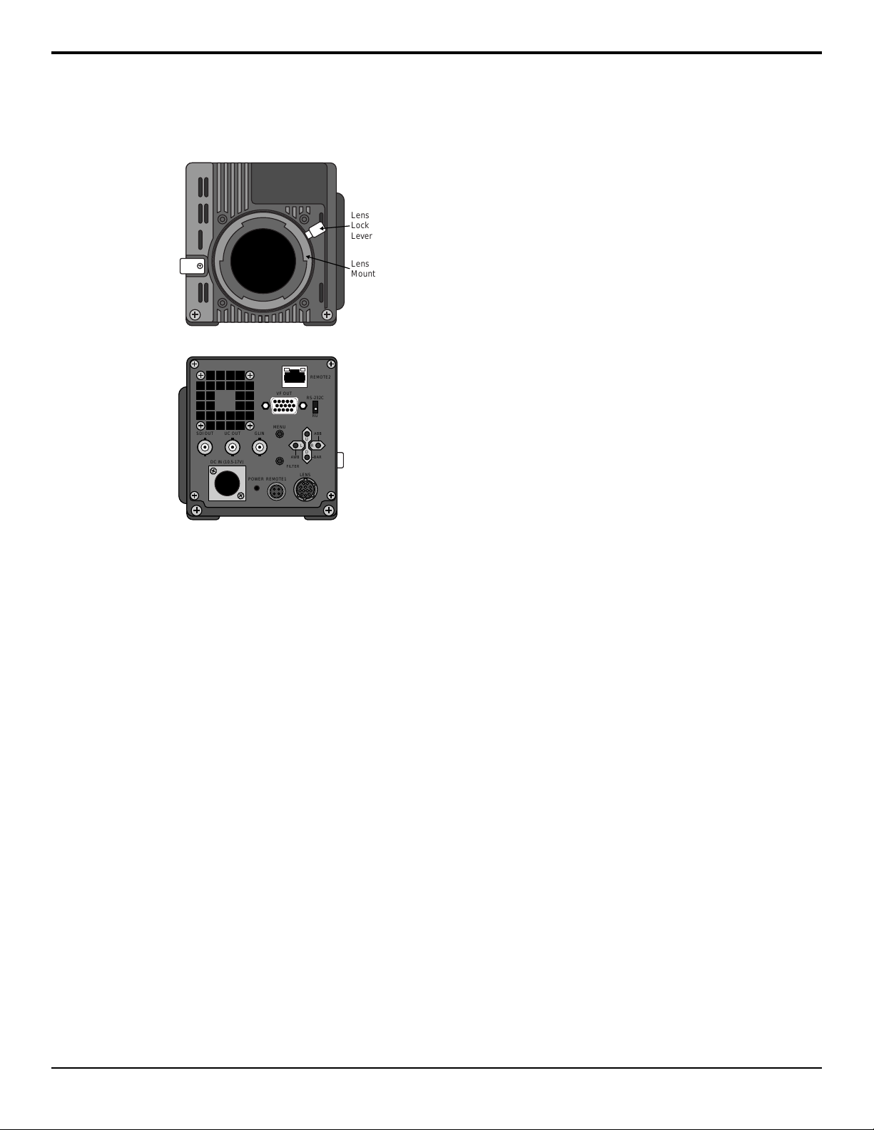
Camera Overview
Figure 1: AC-H200-UCHR Front
Figure 2: AC-H200-UCHR Back
• Lens Mount — Standard bayonet type lens mount.
• Lens Lock Lever — Locks the lens onto the camera.
• SDI OUT — BNC for HD/SD-SDI video output.
This is the main video output of the camera.
• UC OUT — BNC for UltraChromeHR signal.
• GL IN — BNC for Reference in. The camera accepts
Tri-level or Black burst sync.
• DC IN — 4-Pin XLR for 12V DC power (10.5V to
17V) from external brick. Use only the external power
supply provided with your camera.
• POWER — Power indicator shows that power is
being provided to the camera (green).
• REMOTE1 — 4-Pin Multi connector for Remote
Control Unit or direct serial control.
• LENS — 12-Pin Multi connector for lens control.
• FILTER — Button used to set lter control.
• D — Button used for menu navigation (down) or turn
on Color bar signal output. Press the button when the
menu is not active to turn on the color bars.
• R — Button used for menu navigation (right) or to
turn on Automatic Black Balance Adjustment (ABB)
if held for more than 2 seconds.
• U — Button used for menu navigation (up).
• L — Button used for menu navigation (left) or to turn
on Automatic White Balance (AWB) if held for more
than 2 seconds.
• MENU — Button used to access the menu system.
The menu is shown on the MON OUT.
• VF OUT — DB15 connector for external viewnder.
• REMOTE2 — RJ-45 connector for 10/100 BASE-T
ethernet control.
• RS-232C / RU — Switch to set REMOTE1
connector for direct RS-232 serial control or control
by a Remote Control Unit.
ACID AC-H200-UCHR User Manual (v1.0) — Camera Overview • 11
Page 12

Camera and Lens Setup
The camera does not come with a lens, but can easy
accept all Canon®or Fujinon®lenses.
To Install a Lens
1.
Disconnect power from the DC IN port at the back
of the camera.
2.
Rotate the Lens Lock Lever counter-clockwise
to unlock the mount cap.
Align the lens center mark with the indent at the
3.
upper part of the lense mark and install the lens.
4.
Rotate the Lens Lock Lever clock-wise to lock
the lense onto the camera.
Connect the lense control cable from the lens to the
5.
LENS port on the back of the camera.
Note: A cable clamp is provided at the front of the camera
for cable management.
Following the installation of the lens you may need to
adjust the lens ange back, white shading, auto iris speed,
or iris close limit, depending on the lens you are
installing.
To Adjust the Flange Back Distance
You will need a Flange Back Adjust Chart for this
procedure.
The Flange Back Distance (FBD) is the distance between
the mounting ange on the camera mount and the lm
plane. This is the point where the lens focuses the image
onto the image sensor. When you install a new lens on
the camera mount, or there is an extreme change in
temperature, the lens may need to be adjusted.
Set the Iris control on the lens to manual.
1.
Set up the camera and the ange back adjustment
2.
chart about 10 feet (3 metres) away from each other.
Open the iris all the way and adjust the light to
3.
obtain the correct video input level.
Tip: If the video level is too high, use an ND filter or
increase the shutter speed.
Adjust the ange back adjustment ring until the
8.
image sharp.
Repeat these steps until the image is consistently
9.
sharp at both zoom settings.
Tighten the setscrew on the ange back adjustment
10.
ring.
To Adjust the White Shading
You will need an HD waveform monitor and a very even
light source.
The white shading is the adjustment of the individual
red, green, and blue color channels in the camera to
compensate for uneven color distribution across an image.
Each lens and image sensor have their own characteristics
that need to be compensated for to produce a consistent
color distribution.
White shading is measured both horizontally and
vertically across the image.
Tip: If you notice flickering on the monitor, this can be the result
of fluorescent or mercury lighting.
1.
Press MENU and select MAINTENANCE >
SHUTTER > SHUTTER and select OFF.
2.
Press MENU and select COLOR > MASTER
GAIN > PRESET and select 0dB.
3.
Press MENU and select MAINTENANCE > WHT
SHADING > EXTENDER and select OFF.
4.
Press MENU and select MAINTENANCE > WHT
SHADING > H SHADING and use the RGB
settings to adjust each color channel until they are
equal in the waveform monitor.
5.
Repeat these last steps for the V SHADING.
Navigate back to the WHT SHADINGmenu.
6.
7.
Select WHT SHADING and press the R button for
1 second.
Boxes will appear on the viewnder and ash,
indicating that the automatic white shading is being
performed.
If present, turn the extender on and repeat the
8.
procedure.
Loosen the setscrew on the ange back adjust ring
4.
on your lens.
Zoom in on the chart.
5.
Adjust the focus until the image is sharp. If you are
6.
using a ange back adjustment chart, the center of
the chart will appear blurry.
Zoom out from the chart.
7.
12 • Camera and Lens Setup — ACID AC-H200-UCHR User Manual (v1.0)
To Select a Filter Setting
The lter helps to correct for different lighting conditions
and sources. The proper lter needs to be selected in the
camera for proper white balancing.
1.
Press and hold the FILTER button and use the L
and R buttons to select the Neutral Density (ND)
lter you are using.
Page 13
•
1 — Clear
•
2 — 1/4ND
•
3 — 1/16ND
•
4 — 1/64ND
2.
Press and hold the FILTER button and use the U
and D buttons to select the Color Compensation
(ECC) lter you are using.
•
A — 3,200K
•
B — 4,300K
•
C — 5,600K
•
D — 6,300K
•
E — 8,000K
Note: The ECC filter does not operate when W.BAL MODE
is set to AUTO on the WHITE GAIN menu.
To Adjust the White Balance
You will need a white balance card that you can zoom
in on to take up at least 1/5 of the screen width and hight.
The card should be placed in the same lighting conditions
as the scene you want to shoot, without any high
luminosity sources (such as a spotlight) in the scene.
The White Balance (WB) adjusts the colors in the image
to compensate for various light sources that can tint the
image. White will appear as white, without other color
tints, when the image is properly white balanced.
Tip: You should adjust the white balance whenever there has
been a change in lighting conditions.
Ensure that the ltering is set for the current lighting
1.
conditions.
2.
Press MENU and select COLOR > WHITE GAIN
> W. BAL MODE and select MEMORY.
Zoom the camera in on the white balance card and
3.
adjust the iris control as required.
4.
Press MENU to close the menu system and hold the
L button for 2 seconds.
The camera will adjust the white balance
automatically over several seconds. When the
adjustment is complete the display will show the
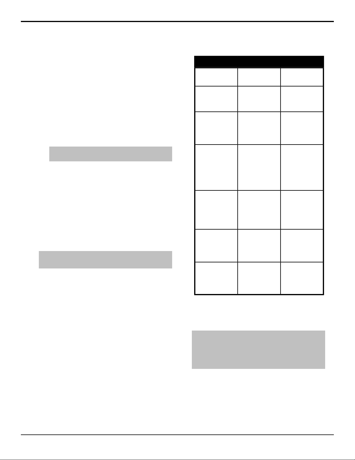
results of the white balance adjustment. Refer to
Table 1: Auto White Balance Adjustment Results on
page 13 for a list of messages.
Take any corrective action and repeat the procedure
5.
if required.
Table 1: Auto White Balance Adjustment Results
CorrectionCauseMessage
AUTO WHITE: OK
C. TEMP: ####K
AUTO WHITE: NG
CHANGE TO CAM
TRY AGAIN
AUTO WHITE: NG
CHANGE WHITE
BAL TO MEM TRY
AGAIN
AUTO WHITE: NG
LOW LIGHT TRY
AGAIN
AUTO WHITE: NG
LEVEL HIGH TRY
AGAIN
AUTO WHITE: NG
C. TEMP. HIGH
CHANGE FILTER
TRY AGAIN
AUTO WHITE: NG
C. TEMP. LOW
CHANGE FILTER
TRY AGAIN
was successful.
Camera is
outputting color
bars.
W.BAL MODE is
set to PRESET or
AUTO.
Light levels are too
low.
Light levels are too
high.
Color temperature
adjustment is too
high.
Color temperature
adjustment is too
low.
--Auto white balance
Press the D button
to turn off color bars.
Set W.BAL MODE
to MEMORY.
Increase the light
levels or the master
gain. If manual iris
control is being
used, adjust the iris
stop.
Decrease the
master gain. If
manual iris control is
being used, adjust
the iris stop.
Change the ECC
filter.
Change the ECC
filter.
To Adjust the Black Balance
The Black Balance (BB) is similar to white balance
except that it is performed on black instead of white.
Note: You should adjust the white balance both before and after
adjusting the black balance. Black balance should be adjusted
when the camera has been idle for an extended period of time,
there is a large change in ambient temperature, or when the
gamma setting has changed.
Ensure that the ltering is set for the current lighting
1.
conditions.
2.
With the menu system off, press and hold the R
button for 2 seconds.
The lens iris will close and the camera will adjust
the black balance automatically over several seconds.
When the adjustment is complete the display will
ACID AC-H200-UCHR User Manual (v1.0) — Camera and Lens Setup • 13
Page 14
show the results of the black balance adjustment.
Gate
Marker
Refer to Table 2: Auto Black Balance Adjustment
Results on page 14 for a list of messages.
Take any corrective action and repeat the procedure
3.
if required.
Table 2: Auto Black Balance Adjustment Results
AUTO BLACK: OK
AUTO BLACK: NG
CHANGE TO CAM
TRY AGAIN
AUTO BLACK: NG
IRIS NOT CLOSED
TRY AGAIN
AUTO BLACK: NG
??? TRY AGAIN
was successful.
Camera is
outputting color
bars.
The iris is not
closed.
Range is exceeded,
cannot adjust.
CorrectionCauseMessage
--Auto black balance
Press the D button
to turn off color bars.
If manual iris control
is being used, adjust
the iris to fully
closed. The camera
will adjust the gain
automatically during
the test. Flicker or
noise may appear
on screen during the
adjustment, this is
normal.
Check the lens
cable connection. If
the cable is correct
there is a fault in the
lens or the camera.
Contact technical
support.
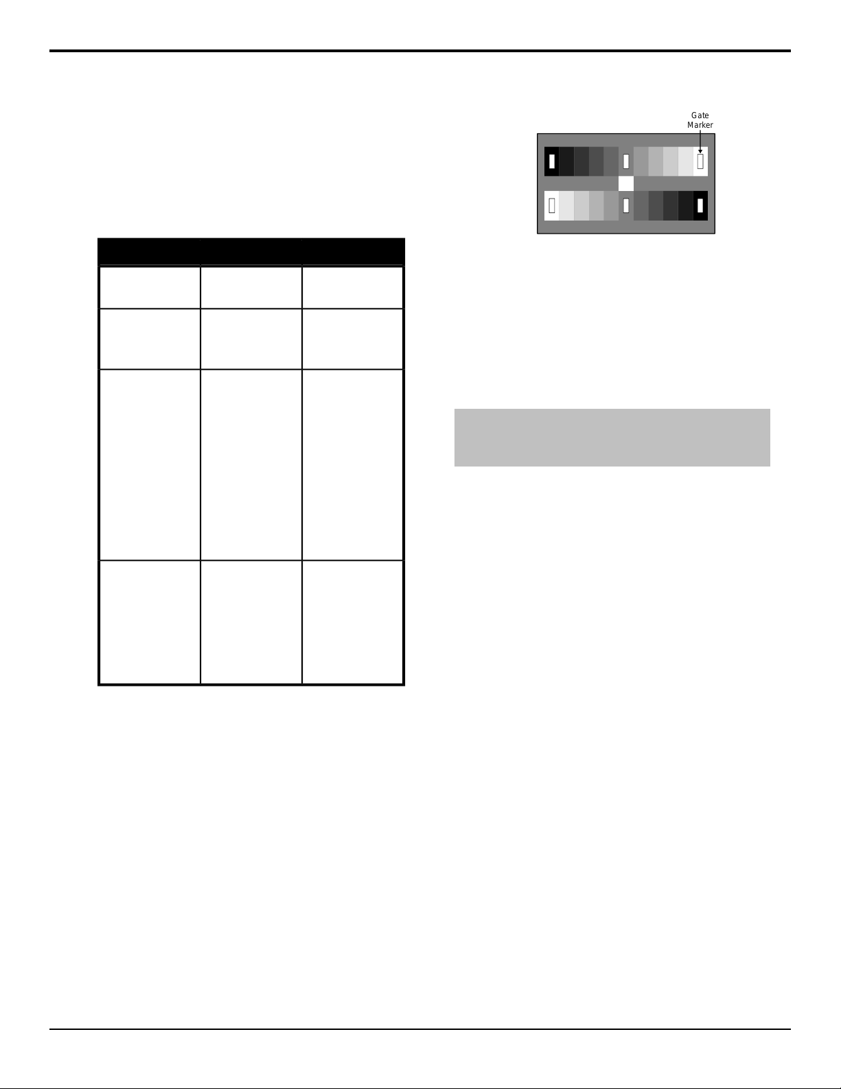
Figure 3: Gate Marker Alignment
3.
Press and hold the R button for 1 second.
The camera will automatically align Black, Gain,
Flare, and Gamma to preset values.
To Adjust the Shutter Mode
Select the shutter mode and speed for the environment
you are shooting.
Note: Camera sensitivity declines as shutter speed increases.
If the iris is set to auto, the iris opens at increased shutter speed
and the depth of focus decreases.
1.
Press MENU and select MAINTENANCE >
SHUTTER > SHUTTER and select the shutter
mode for your environment.
•
OFF — shutter is off.
•
PRESET — clear image of quick moving
objects.
•
VARIABLE — prevent rolling bar when
shooting a computer monitor or TV by matching
the refresh rate of display.
•
AES — shutter speed is automatically adjusted.
2.
Select SHUTTER PRE or SHUTTER VAR and
select the shutter speed you want to use.
To Adjust the Grayscale Setup
You will need an 11-Step Grayscale Chart for this
procedure.
The Grayscale adjusts the exposure levels of the camera
across all the steps in the grayscale chart to ensure proper
color reproduction across the entire range of tones.
1.
Press MENU and select MAINTENANCE > AUTO
SETUP > GRAY SCALE.
Frame the camera on the Grayscale chart to align
2.
the 6 cursors shown on the monitor display as shown
on the gure below. The camera will adjust the iris
automatically once the setup is executed.
14 • Camera and Lens Setup — ACID AC-H200-UCHR User Manual (v1.0)
Page 15

Network Connections
The UltraChromeHR camera can be controlled either
through a menu system on the viewnder output of the
camera, or using DashBoard. To connect to the camera
from DashBoard, you must establish a network
connection to the camera from the DashBoard computer.
The UltraChromeHR camera comes set with a static IP
address from the factory. The IP address is set to
192.168.1.10 by default and can be changed using the
menu system.
You need the IP address of the camera to be able to
connect to it from DashBoard.
To Change the IP Address
1.
Press MENU and select MAINTENANCE > LAN
SETTING
The current network setting for the camera are shown
on the menu.
2.
Select IP CONF and press the R button.
3.
Select OCTET1, press the R and L button to select
the rst part of the address.
Repeat these steps for the remaining octets you want
4.
to set.
5.
Select SEND and press the R button to store the
new value to the temporary buffer.
Return to the LAN SETTING menu.
6.
7.
Select SUBNET CONF and press the R button.
8.
Select OCTET1, press the R and L button to select
the rst part of the address.
Repeat these steps for the remaining octets you want
9.
to set.
10.
Select SEND and press the R button to store the
new value to the temporary buffer.
Return to the LAN SETTING menu.
11.
12.
Select GATEWAY CONF and press the R button.
13.
Select OCTET1, press the R and L button to select
the rst part of the address.
Repeat these steps for the remaining octets you want
14.
to set.
15.
Select SEND and press the R button to store the
new value to the temporary buffer.
Return to the LAN SETTING menu.
16.
Verify the new temporary network setting that are
17.
shown on the CONF line for the IP address, subnet
mask, and gateway.
18.
Select SET DATA and press the R button to set the
new network values.
ACID AC-H200-UCHR User Manual (v1.0) — Network Connections • 15
Page 16

DashBoard
The DashBoard control system allows remote access to
multiple pieces of Ross Video equipment, including
openGear®cards, Carbonite production switchers,
BlackStorm video servers, and ACID UltraChromeHR
cameras.
Download and install the latest version of DashBoard
from http://www.opengear.tv/. Review the documentation
that comes with DashBoard for information on installing
and launching DashBoard.
Tip: For detailed instructions on using DashBoard with ACID
UltraChromeHR, navigate to the online help at
http://help.rossvideo.com/acid.
Connecting to the Camera from DashBoard
You must manually connect to the camera from
DashBoard using the IP address of the camera. Once
connected, DashBoard will remember the connection
until you remove it
To Connect to the Camera from DashBoard
You need the IP address of your camera to connect to it
manually from DashBoard.
1.
Click File > New > Other....
2.
Expand the Camera Control folder.
3.
Select New Camera and click Next.
4.
In the IP Address eld, enter the IP address of the
camera.
5.
Click Finish.
The camera appears in the Tree View.
16 • DashBoard — ACID AC-H200-UCHR User Manual (v1.0)
Page 17
Viewfinder Display
E
1 A M 0dB F8. 0
1 / 1000 Z : 99 F : 255
1
5 6 7 8 9
2 3 4
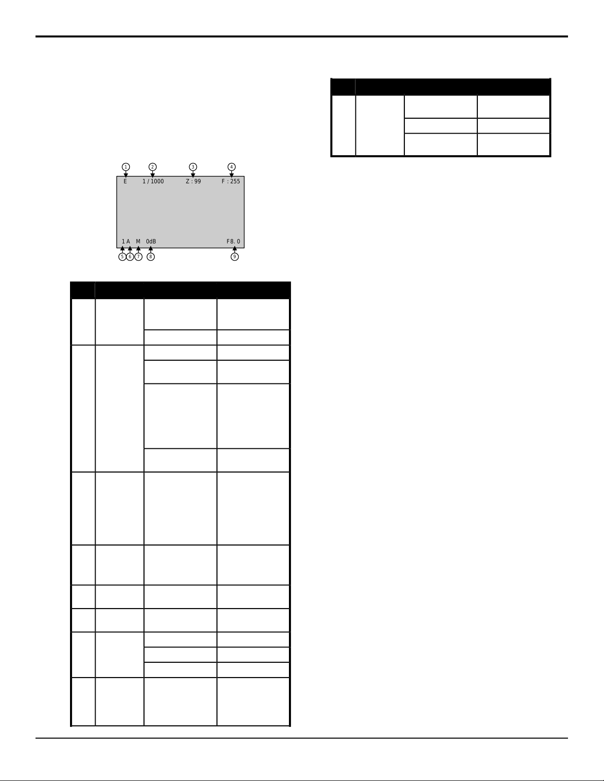
The status overlay provides information related to camera
setting and operation. You can select what and where
information is presented on the display from the VF
menu.
Figure 4: Viewfinder Display Overlay
-no indication-Extender1
or 1/60 (50i/p)
1/2000, 1/4000,
1/10,000 1.07s to
1/59.94, 60.15 to
1/9633 (59.94i/p, 60i/p)
1.28s to 1/50, 1/50.17
to 1/11,250 (50i/p)
AES
0 - 99Zoom3
0 - 255Focus4
1 - 4ND Filter5
A - EECC Filter6
Master Gain8
-6dB, -3dB, 0dB, 3dB,
6dB, 9dB, 12dB, 15dB,
18dB, 21dB, 24dB,
27dB, 30dB, 33dB,
36dB
DescriptionStatusItem#
Extender is at X1 or
lens cable is not
connected.
Extender is at X2.E
OffOFFShutter2
PRESET1/100 (59.94i/p, 60i/p)
VARIABLE1/250, 1/500, 1/1000,
Automatic Electronic
Shutter
Indicates the
approximate zoom
position of the lens
between wide angle (0)
and telephoto (99).
Value is relative
closeness to telephoto
side.
Indicates the focus
position of the lens as
a numeric value (255 =
infinity).
Shows the type of ND
filter currently selected.
Shows the type of ECC
filter currently selected.
Preset ModePWhite Balance7
Memory ModeM
Auto ModeA
Shows the current
value of the master
gain.
F1.4 - F22Iris F-Stop9
***
DescriptionStatusItem#
Current Iris F-Stop
setting.
Iris is closed.CLS
Lens cable is not
connected.
ACID AC-H200-UCHR User Manual (v1.0) — Viewfinder Display • 17
Page 18
Menu System
The menu system is displayed on the SDI OUT output
BNC or the viewnder and allows you to set up and
congure various aspects of the camera. The menu
system is accessed by pressing the MENU button and
using the L, R, U, and D buttons to make selections.
A menu item with a > symbol indicates that there is a
sub-menu below this selection or another page of the
current menu. Press R to go into this sub-menu, or the
next page. Press L where you see a < symbol to go to the
previous page in a menu or up a level in the menu tree.
Tip: The number of > symbols next to a menu item indicate the
number of pages in that sub-menu.
Color Menus
Color Menu
├ Master Gain
│ ├ Preset
│ ├ Mode
│ ├ AGC Limit
│ ├ ACL Setting
│ ├ Low Set
│ ├ Mid Set
│ └ High Set
├ White Gain
│ ├ W. Bal Mode
│ ├ R Gain
│ ├ G Gain
│ ├ B Gain
│ └ Video CTemp
├ Black/Flare
│ ├ R Black
│ ├ G Black
│ ├ B Black
│ ├ R Flare
│ ├ G Flare
│ ├ B Flare
│ ├ Flare
│ └ M Black
├ Gamma
│ ├ R Gamma
│ ├ G Gamma
│ ├ B Gamma
│ ├ Total Gamma
│ ├ Gamma Table
│ ├ Gamma
│ ├ U Gamma TBL
│ ├ Ultra Gamma
│ ├ HDR
│ ├ HDR Select
│ ├ Blk Str Lev
│ ├ Blk Stretch
│ ├ R Blk Gamma
│ ├ G Blk Gamma
│ ├ B Blk Gamma
│ ├ M Blk Gamma
│ ├ Gamma Range
│ └ Black Gamma
├ Knee/Clip
│ ├ Total Knee
│ ├ R Knee
│ ├ B Knee
│ ├ Total Slope
│ ├ R Slope
│ ├ B Slope
│ ├ Knee
│ ├ Auto Knee
│ ├ Knee Sat
│ ├ Knee Sat
│ ├ White Clip
│ └ White Clip
└ Masking
├ R Hue/Sat
├ Y-R Hue/Sat
├ Y Hue/Sat
├ G-Y Hue/Sat
├ G Hue/Sat
├ C-G Hue/Sat
├ C Hue/Sat
├ B-C Hue/Sat
├ B Hue/Sat
├ M-B Hue/Sat
├ M Hue/Sat
├ R-M Hue/Sat
├ Masking
├ Linear R-G
├ Linear R-B
├ Linear G-R
├ Linear G-B
├ Linear B-R
├ Linear B-G
├ Preset Type
├ Auto Chroma
├ A. Chrom Lev
├ Masking
├ S. Mask Sat/Hue
├ Skin Mask
├ Chroma Sat
└ Chroma Sat
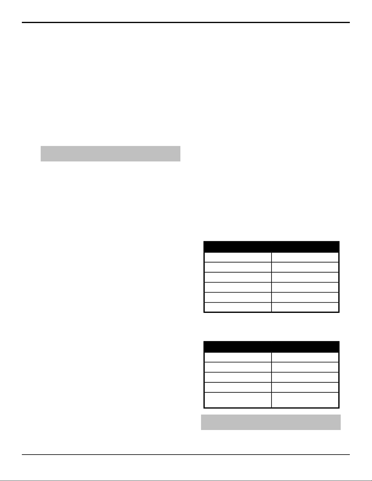
Master Gain
Press MENU and select COLOR > MASTER GAIN
SettingsItem
-6dB to 36dBPRESET
PRESET, AGCMODE
-6dB to +36dBAGC LIMIT
-6dB, -3dB, 0dBLOW SET
0dB to +21dBMID SET
+3dB to +36dBHIGH SET
White Gain
Press MENU and select COLOR > WHITE GAIN
SettingsItem
PRESET, MEMORY, AUTOW. BAL MODE
-128 to 127R GAIN (red gain)
-128 to 127G GAIN (green gain)
-128 to 127B GAIN (blue gain)
VIDEO CTEMP
Note: When W. BAL MODE is set to AUTO the R GAIN, G
GAIN, B GAIN, and ECC filter settings are not available.
(shows current color
temperature)
18 • Menu System — ACID AC-H200-UCHR User Manual (v1.0)
Page 19
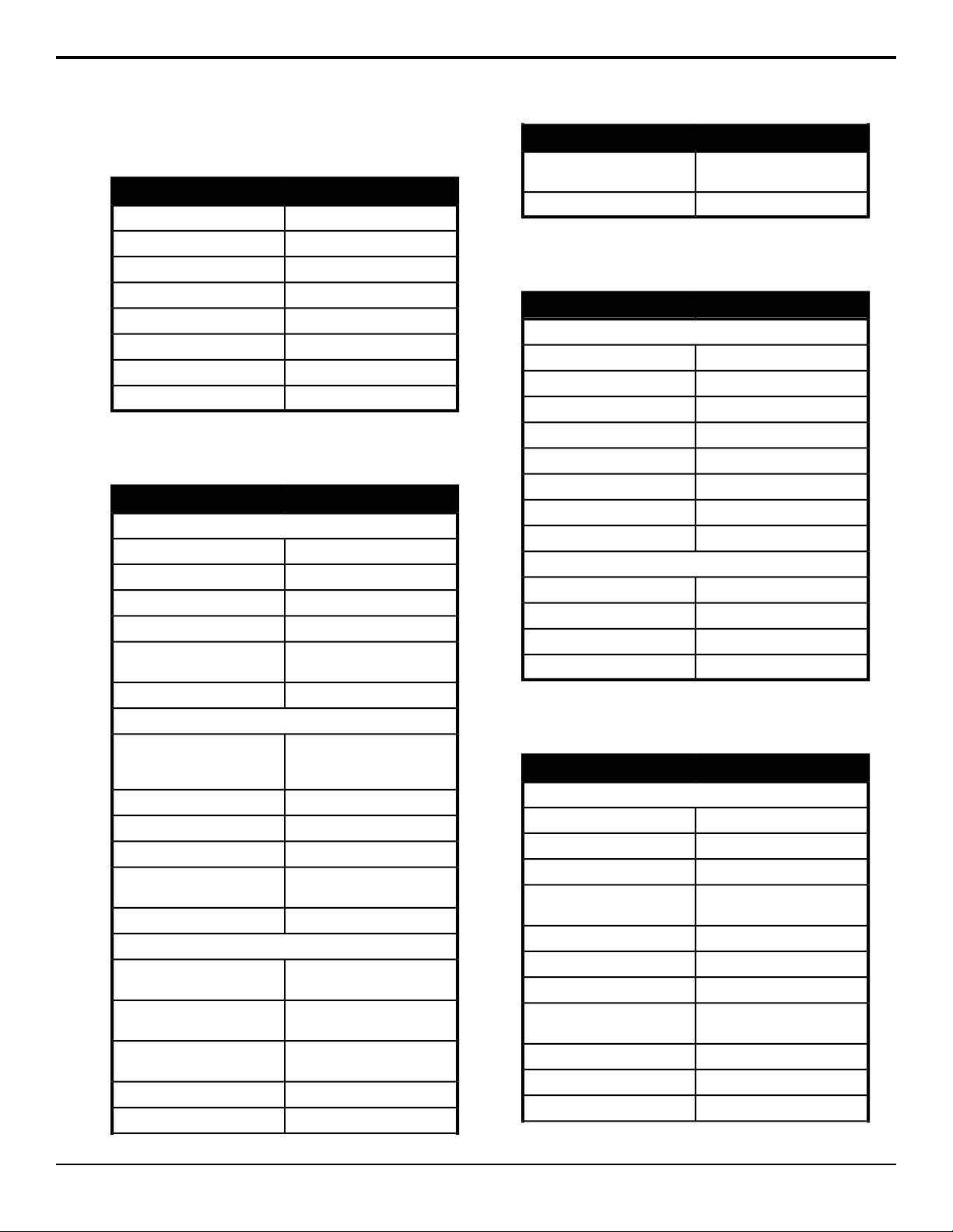
Black/Flare
Press MENU and select COLOR > BLACK/FLARE
SettingsItem
-128 to 127R BLACK (red black level)
-128 to 127G BLACK (green black level)
-128 to 127B BLACK (blue black level)
-128 to 127R FLARE (red flare level)
-128 to 127G FLARE (green flare level)
-128 to 127B FLARE (blue flare level)
ON, OFFFLARE
-128 to 127M. BLACK (master black)
Gamma
Press MENU and select COLOR > GAMMA
SettingsItem
GAMMA 1
R GAMMA (red gamma)
curve value)
U. GAMMA TBL (ultra gamma
curve)
level)
gamma)
gamma)
gamma)
-128 to 127
-128 to 127G GAMMA (green gamma)
-128 to 127B GAMMA (blue gamma)
-128 to 127TOTAL GAMMA
3.0 to 8.0GAMMA TABLE (gamma
ON, OFFGAMMA
GAMMA 2
1(90%), 2(85%), 3(80%),
4(75%), 5(70%), 6(65%),
7(50%)
ON, OFFULTRA GAMMA
ON, OFFHDR (high dynamic range)
HLG600, HLG1200, HPQHDR SELECT
0 to 11BLK STR LEV (black stretch
ON, OFFBLK STRETCH
GAMMA 3
-128 to 127R. BLK GAMMA (red black
-128 to 127G. BLK GAMMA (green black
-128 to 127B. BLK GAMMA (blue black
-128 to 127M. BLK GAMMA
-128 to 127GAMMA RANGE
SettingsItem
(AC-H200-UCHR only)
-128 to 127Gamma Range
ON, OFFBLACK GAMMA
Knee/Clip
Press MENU and select COLOR > KNEE/CLIP
SettingsItem
KNEE/CLIP 1
TOTAL KNEE
-128 to 127
-128 to 127R KNEE
-128 to 127B KNEE
-128 to 127TOTAL SLOPE
-128 to 127R SLOPE
-128 to 127B SLOPE
ON, OFFKNEE
ON, OFFAUTO KNEE
KNEE/CLIP 2
-128 to 127KNEE SAT
ON, OFFKNEE SAT
-128 to 127WHITE CLIP
ON, OFFWHITE CLIP
Masking
Press MENU and select COLOR > MASKING
SettingsItem
MASKING 1
R HUE (red hue)
saturation)
saturation)
-64 to 63
-64 to 63R SAT (red saturation)
-64 to 63Y-R HUE (yellow-red hue)
-64 to 63Y-R SAT (yellow-red
-64 to 63Y HUE (yellow hue)
-64 to 63Y SAT (yellow saturation)
-64 to 63G-Y HUE (green-yellow hue)
-64 to 63G-Y SAT (green-yellow
-64 to 63G HUE (green hue)
-64 to 63G SAT (green saturation)
-64 to 63C-G HUE (cyan-green hue)
ACID AC-H200-UCHR User Manual (v1.0) — Menu System • 19
Page 20
SettingsItem
SettingsItem
saturation)
saturation)
saturation)
saturation)
matrix offset)
matrix offset)
matrix offset)
matrix offset)
matrix offset)
matrix offset)
PRESET TYPE
matrix saturation offset)
color saturation)
hue)
-64 to 63C-G SAT (cyan-green
-64 to 63C HUE (cyan hue)
-64 to 63C SAT (cyan saturation)
-64 to 63B-C HUE (blue-cyan hue)
-64 to 63B-C SAT (blue-cyan
-64 to 63B HUE (blue hue)
-64 to 63B SAT (blue saturation)
-64 to 63M-B HUE (magenta-blue hue)
-64 to 63M-B SAT (magenta-blue
-64 to 63M HUE (magenta hue)
-64 to 63M SAT (magenta saturation)
-64 to 63R-M HUE (red-magenta hue)
-64 to 63R-M SAT (red-magenta
ON, OFFMASKING
MASKING 2
-64 to 63LINEAR R-G (red-green linear
-64 to 63LINEAR R-B (red-blue linear
-64 to 63LINEAR G-R (green-red linear
-64 to 63LINEAR G-B (green-blue linear
-64 to 63LINEAR B-R (blue-red linear
-64 to 63LINEAR B-G (blue-green linear
STANDARD, ITU-709,
SMPTE-240M, SMPTE-WIDE,
NTSC, EBU, OFF
ON, OFFAUTO CHROMA
-64 to 63A. CHROMA LEV (linear
ON, OFFMASKING
MASKING 3
-64 to 63S. MASK. SAT (skin masking
-64 to 63S. MASK. HUE (skin masking
ON, OFFSKIN MASK
-64 to 63CHROMA SAT
ON, OFFCHROMA SAT
Details Menus
Detail Menu
├ Detail
│ ├ Level
│ ├ H Gain
│ ├ V Gain
│ ├ H Crisp
│ ├ V Crisp
│ ├ Level Dep
│ ├ D. Knee Wht
│ ├ D. Knee Blk
│ ├ Detail Knee
│ ├ P/N Balance
│ ├ Knee Detail
│ ├ DTL Source
│ └ Detail
├ Skin DTL
│ ├ Ch Select
│ ├ Chx A. Phase
│ ├ S.DTL Level
│ ├ S.DTL Phase
│ ├ S.DTL Width
│ ├ Threshold
│ ├ Skin Detail
│ ├ Skin Gate
│ ├ Gate Ind.
│ ├ Zoom Depend
│ ├ Sens
│ └ Range
└ High Chroma
├ R
├ G
├ B
└ High Chroma
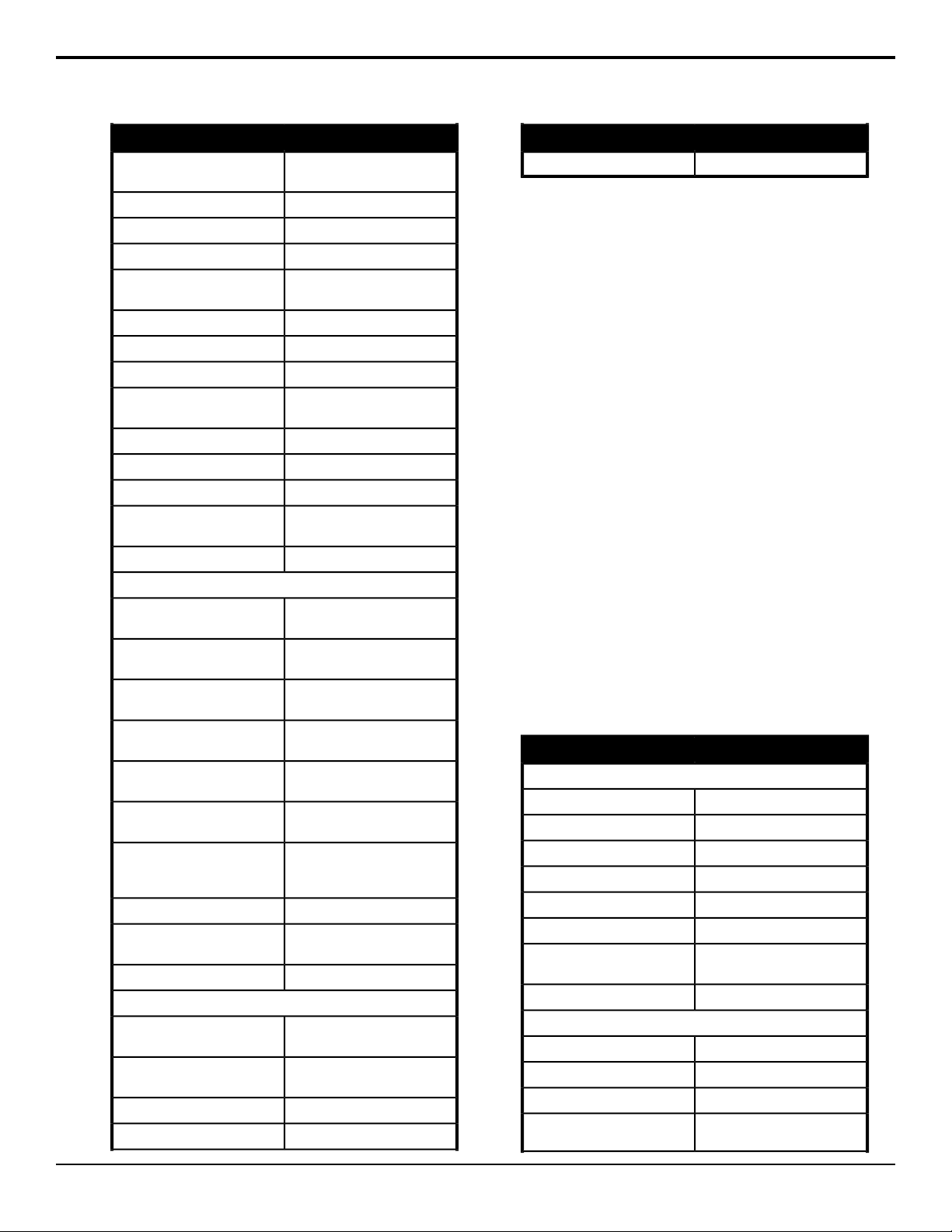
Detail
Press MENU and select DETAIL > DETAIL
SettingsItem
DETAIL 1
LEVEL (detail level)
of detail)
(positive/negative)
-128 to 127
-128 to 127H GAIN (horizontal gain)
-128 to 127V GAIN (vertical gain)
-128 to 127H CRISP (horizontal crispness)
-128 to 127V CRISP (vertical crispness)
-128 to 127LEVEL DEP
13MHz to 19MHzDTL FREQ (boost frequency
ON, OFFDETAIL
DETAIL 2
-128 to 127D. KNEE WHT
-128 to 127D. KNEE BLK
ON, OFFDETAIL KNEE
4/8, 5/8, 6/8, 8/8, 8/6, 8/5, 8/4P/N BALANCE
20 • Menu System — ACID AC-H200-UCHR User Manual (v1.0)
Page 21
SettingsItem
-128 to 127KNEE DETAIL
G, R+G, R+G+BDTL SOURCE
ON, OFFDETAIL
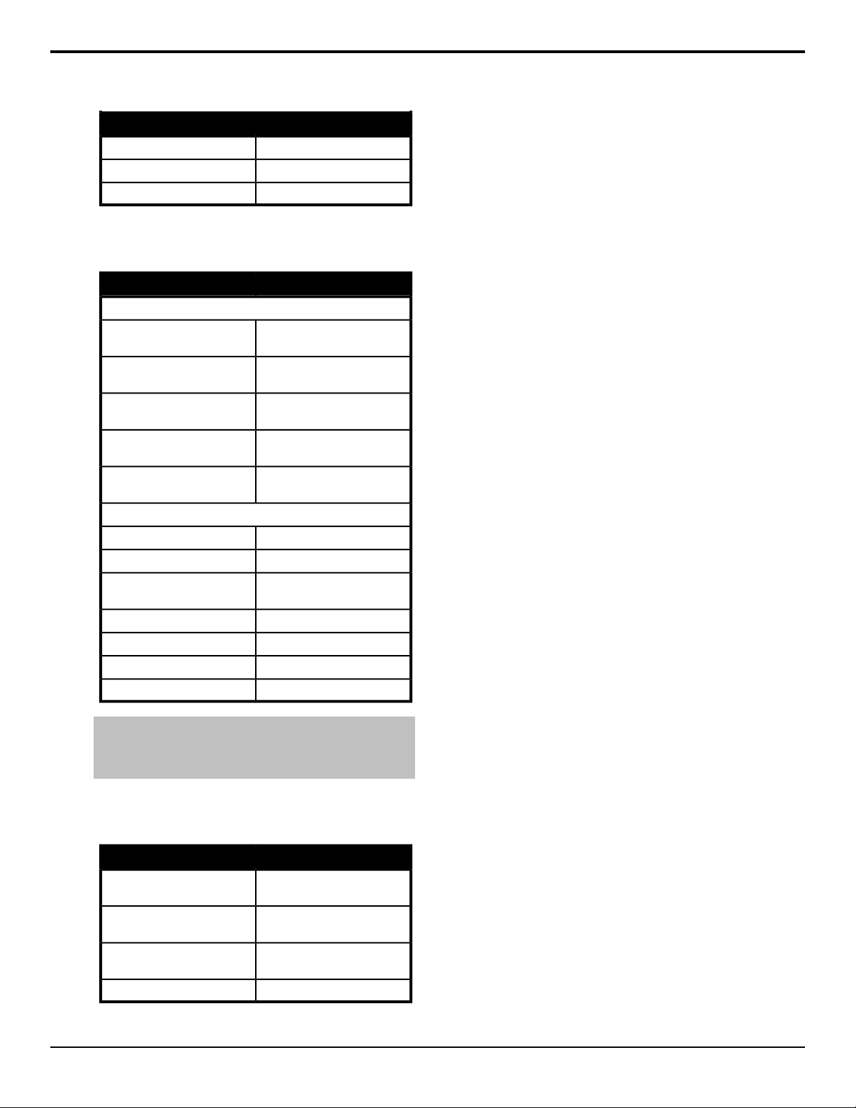
Skin Detail
Press MENU and select DETAIL > SKIN DTL
SettingsItem
SKIN DTL 1
CH SELECT (channel select
for skin tone detail)
PHASE
level)
S. DTL PHASE (skin tone
detail phase)
detail phase range)
gate)
Note: * When you select CHX A. PHASE a marker is shown
on the monitor. Move the camera to place the marker over the
skin tone you want to detect and press R for 1 second. This
functionality can also be accessed from the AUTO SETUP menu.
1ch, 2ch, 1ch+2ch
(see note*)CH1. A. PHASE/CH2. A.
-128 to 127S. DTL LEVEL (skin tone detail
-128 to 127 (R-Mg, Mg-B,
B-Cy, Cy-G, G-Ye, Ye-R)
-128 to 127S. DTL WIDTH (skin tone
SKIN DTL 2
-128 to 127THRESHOLD
ON, OFFSKIN DETAIL
ON, OFFSKIN GATE (skin tone detail
1ch, 2chGATE IND.
ON, OFFZOOM DEPEND
0 to 99SENS
0 to 99RANGE
High Chroma
Press MENU and select DETAIL > HIGH CHROMA
SettingsItem
red)
green)
blue)
-128 to 127R (detail in high-chrominance
-128 to 127G (detail in high-chrominance
-128 to 127B (detail in high-chrominance
ON, OFFHIGH CHROMA
Maintenance Menus
Maintenance Menus
├ Auto Setup
│ ├ Chx.A.Phase
│ ├ Gray Scale
│ ├ Black Lev
│ ├ Flare Lev
│ └ Gamma Lev
├ White Shading
│ ├ Lens File
│ ├ Extender
│ └ Wht Shading
├ Horizontal Shading
│ ├ Lens File
│ ├ Extender
│ ├ R H Saw
│ ├ G H Saw
│ ├ B H Saw
│ ├ R H Para
│ ├ G H Para
│ └ B H Para
├ Vertical Shading
│ ├ Lens File
│ ├ Extender
│ ├ R V Saw
│ ├ G V Saw
│ ├ B V Saw
│ ├ R V Para
│ ├ G V Para
│ └ B V Para
├ Auto Iris
│ ├ Auto Iris
│ ├ Iris Cont
│ ├ Lens File
│ ├ Iris Speed
│ ├ Open Limit
│ └ Close Limit
├ ALC Setting
│ ├ Shutter
│ ├ Auto Iris
│ ├ M. Gain Mode
│ ├ ALC Trim
│ ├ Iris Speed
│ ├ Peak/Ave
│ └ ALC Gate
├ Shutter
│ ├ Shutter
│ ├ Shutter Pre
│ └ Shutter Var
├ System
│ ├ Camera ID
│ ├ Fan Mode
│ ├ GL H Phase
│ └ Para Mode
├ LAN Setting
│ ├ IP Setting
│ ├ Subnet Setting
│ └ Gateway Setting
├ Time/Date
│ ├ (mode)
│ ├ Date Disp
│ ├ Time Disp
│ ├ Year
│ ├ Month
│ ├ Day
│ ├ Hour
│ ├ Minute
│ └ Set Data
├ Format
│ ├ SDI Out
│ ├ UC Out
│ ├ UC Mode
│ ├ Scan Rate
│ └ Set Data
├ Remote
│ ├ Baud Rate
ACID AC-H200-UCHR User Manual (v1.0) — Menu System • 21
Page 22
│ └ Iris Return
├ Check
│ ├ Test
│ ├ Gamma
│ ├ Detail
│ ├ Masking
│ ├ Knee
│ ├ Character
│ ├ Model
│ ├ CPU Ver.
│ ├ Check Sum
│ └ Video Ver.
└ RLAC
├ RLAC
└ Status
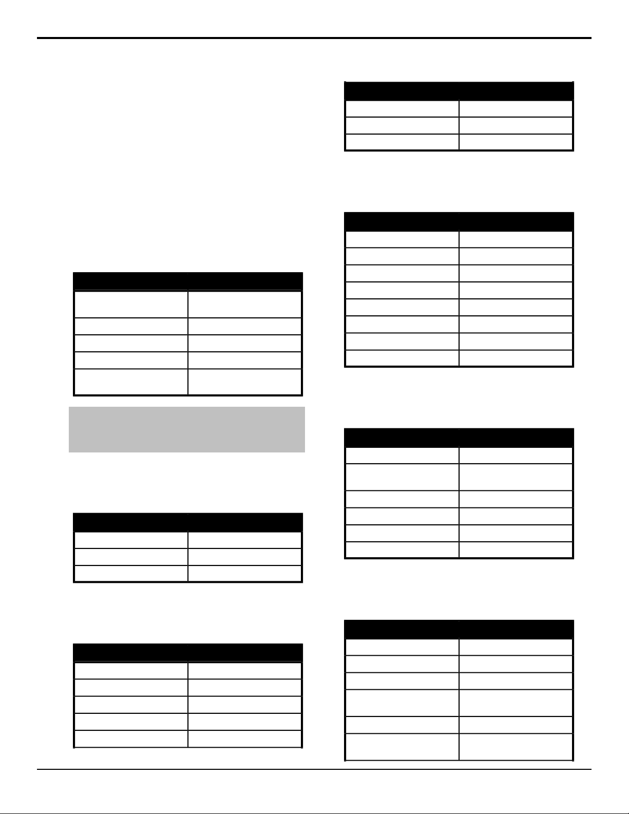
Auto Setup
Press MENU and select MAINTENANCE > AUTO
SETUP
SettingsItem
PHASE
GAMMA LEV
Note: * When you select CHX A. PHASE a marker is shown
on the monitor. Move the camera to place the marker over the
skin tone you want to detect and press R for 1 second. This
functionality can also be accessed from the SKIN DTL menu.
(see note*)CH1. A. PHASE/CH2. A.
(auto gray scale setup)GRAY SCALE
0.0% to 12.35% (0.5% steps)BLACK LEV
0.0% to 24.70% (0.1% steps)FLARE LEV
42.20% to 67.70% (0.1%
steps)
White Shading
Press MENU and select MAINTENANCE > WHT
SHADING
SettingsItem
LENS 1 to LENS 8LENS FILE
OFF, **, x2, x0.8EXTENDER
(auto white shading)WHT SHADING
Horizontal Shading
Press MENU and select MAINTENANCE > WHT
SHADING > H SHADING
SettingsItem
LENS 1 to LENS 8LENS FILE
OFF, **, x2, x0.8EXTENDER
-128 to 127R H SAW (red horizontal)
-128 to 127G H SAW (green horizontal)
-128 to 127B H SAW (blue horizontal)
SettingsItem
-128 to 127R H PARA (red horizontal)
-128 to 127G H PARA (green horizontal)
-128 to 127B H PARA (blue horizontal)
Vertical Shading
Press MENU and select MAINTENANCE > WHT
SHADING > V SHADING
SettingsItem
LENS 1 to LENS 8LENS FILE
OFF, **, x2, x0.8EXTENDER
-128 to 127R V SAW (red vertical)
-128 to 127G V SAW (green vertical)
-128 to 127B V SAW (blue vertical)
-128 to 127R V PARA (red vertical)
-128 to 127G V PARA (green vertical)
-128 to 127B V PARA (blue vertical)
Auto Iris
Press MENU and select MAINTENANCE > AUTO
IRIS
SettingsItem
REMOTE, AUTOAUTO IRIS
IRIS CONT
-128 to 127 (not available when
using RU unit)
LENS 1 to LENS 8LENS FILE
-128 to 127IRIS SPEED
0 to 127OPEN LIMIT
-128 to -1CLOSE LIMIT
ALC Setting
Press MENU and select MAINTENANCE > AUTO
IRIS > ALC SETTING
SettingsItem
OFF, ONSHUTTER
REMOTE, AUTOAUTO IRIS
PRESET, AUTOM. GAIN MODE
ALC TRIM
average)
-128 to 127 (not available when
using RU unit)
-128 to 127IRIS SPEED
0/10, 1/9, 2/8, 3/7, 4/6, 5/5PEAK/AVE (peak and
22 • Menu System — ACID AC-H200-UCHR User Manual (v1.0)
Page 23
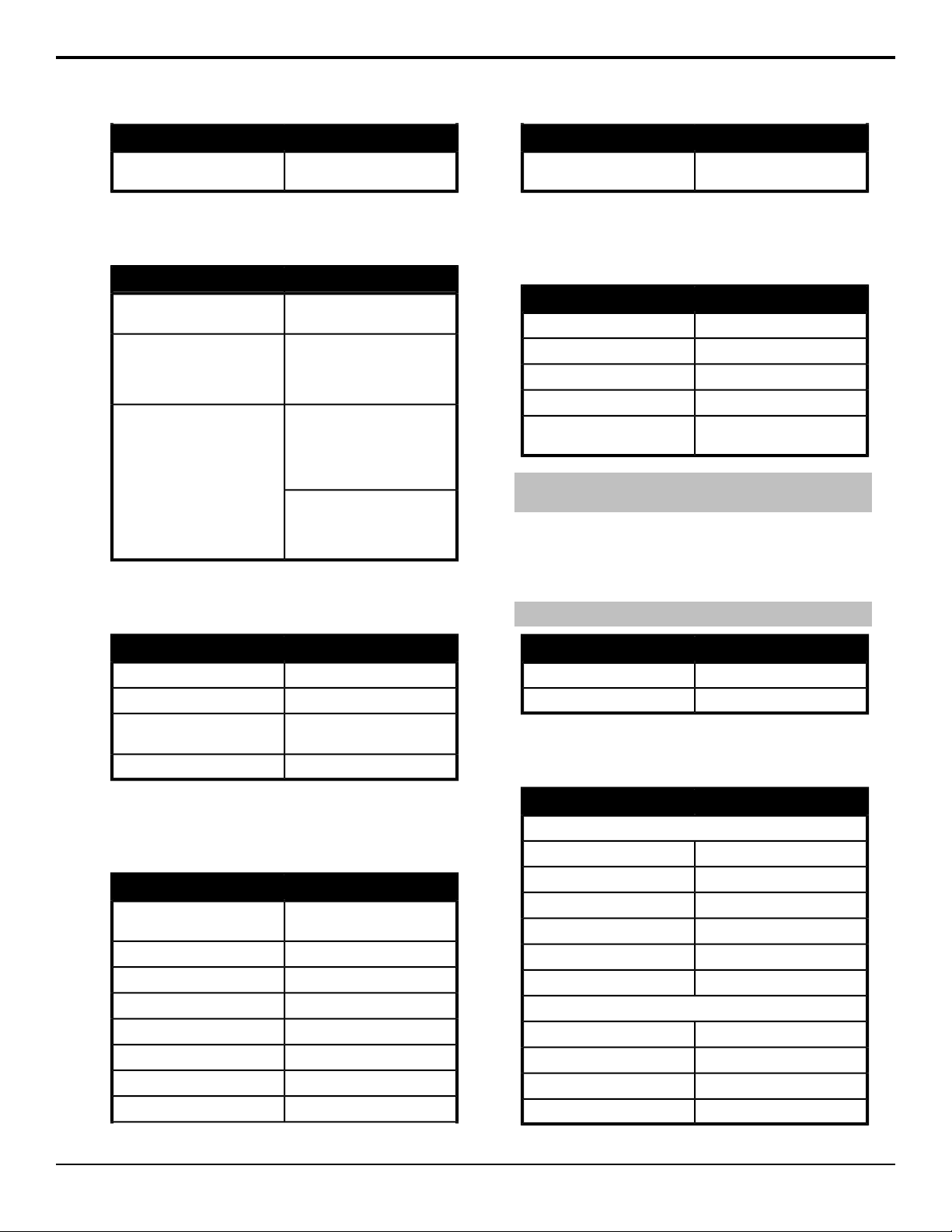
SettingsItem
SettingsItem
shape/size)
1 to 6ALC GATE (auto iris gate
Shutter
Press MENU and select MAINTENANCE > SHUTTER
SettingsItem
SHUTTER
SHUTTER PRE
SHUTTER VAR
OFF, PRESET, VARIABLE,
AES
1/60 (50i,50p), 1/100
(59.94i,59.94p,60i, 60p), 1/250,
1/500, 1/1000, 1/2000, 1/4000,
1/10000
59.94i, 59.94p, 60i, 60p —
1.07s(36dB), 0.53s(30dB),
0.27s(24dB), 0.13s(18dB),
0.07s(12dB), 0.03s(6dB),
1/60.15 to 1/9633
50i, 50p — 1.28s(36dB),
0.64s(30dB), 0.32s(24dB),
0.16s(18dB), 0.08s(12dB),
0.04s(6dB), 1/50.17 to 1/11250
System
Press MENU and select MAINTENANCE > SYSTEM
SET DATA
(press R button to set date and
time)
Format
Press MENU and select MAINTENANCE > SYSTEM
> FORMAT
SettingsItem
1080i, 1080p, 720pSDI OUT
1080i, 1080p, 720pUC OUT
4:2:2, 0:4:4*UC MODE
59.94Hz, 50Hz, 60HzSCAN RATE
SET DATA
Note: * When UC MODE is set to 0:4:4, the SDI OUT is locked
to the same format as the UC OUT.
(press R button to set output
formats)
Remote
Press MENU and select MAINTENANCE > SYSTEM
> REMOTE
Note: These setting apply to the REMOTE1 port only.
SettingsItem
1 - 99CAMERA ID
OFF, AUTO, LOW, HIGHFAN MODE
horizontal phase)
-512 to 511GL H PHASE (gen-lock
OFF, ONPARA MODE
Time/Date
Press MENU and select MAINTENANCE > SYSTEM
> TIME/DATE
SettingsItem
(mode)
DD-MM-YYYY, MM-DD,YYYY,
YYYY-MM-DD
OFF, ONDATE DISP
OFF, ONTIME DISP
2000 to 2099YEAR
1 to 12MONTH
1 to 31DAY
0 to 23HOUR
0 to 59MINUTE
SettingsItem
9600bps, 19200bpsBAUD RATE
OFF, ONIRIS RETURN
Check
Press MENU and select MAINTENANCE > CHECK
SettingsItem
CHECK 1
TEST (test signal)
OFF, ON
OFF, ONGAMMA
OFF, ONDETAIL
OFF, ONMASKING
OFF, ONKNEE
OFF, ONCHARACTER*
CHECK 2
(camera model)MODEL
(CPU firmware version)CPU Ver.
(CPU firmware checksum)Check SUM
(video FPGA firmware version)VIDEO Ver.
ACID AC-H200-UCHR User Manual (v1.0) — Menu System • 23
Page 24
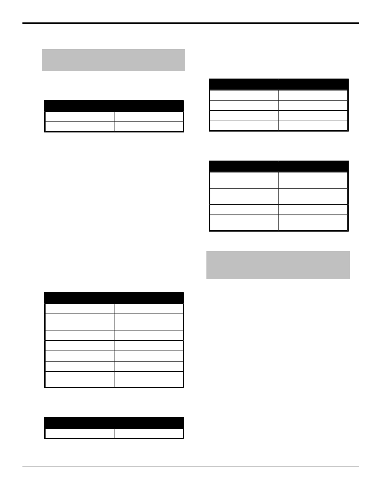
Note: * If you turn Character off, the onscreen menu is turned
off. You must press and hold the MENU button to turn the menus
back on (this turns Character back to on).
Auto Iris
Press MENU and select FILE > LENS FILE > AUTO
IRIS
RLAC (Real-time Lens Aberration Correction)
Press MENU and select MAINTENANCE > RLAC
SettingsItem
OFF, ONRLAC
DISABLE, ENABLE, READINGSTATUS
File Menus
File Menus
├ Scene File
│ ├ Scene File
│ ├ Store File
│ ├ Store
│ ├ Lens File
│ ├ Black Lev
│ ├ Flare Lev
│ └ Gamma Lev
├ Lens File
│ └ Lens File
├ Auto Iris
│ ├ Lens File
│ ├ Iris Speed
│ ├ Open Limit
│ └ Close Limit
└ Register
├ R H Regi
├ G H Regi
├ R V Regi
└ G V Regi
Scene File
Press MENU and select FILE > SCENE FILE
SettingsItem
0 to 8, PRESETSCENE FILE (load scene file)
to store to)
GAMMA LEV
Lens File
Press MENU and select FILE > LENS FILE
0 to 8STORE FILE (select location
(press R to store scene)STORE
LENS 1 to LENS 8LENS FILE
0.0% to 12.35% (0.5% steps)BLACK LEV
0.0% to 24.70% (0.1% steps)FLARE LEV
42.20% to 67.70% (0.1%
steps)
SettingsItem
LENS 1 to LENS 8LENS FILE
SettingsItem
LENS 1 to LENS 8LENS FILE
-128 to 127IRIS SPEED
0 to 127OPEN LIMIT
-128 to -1CLOSE LIMIT
Register
Press MENU and select FILE > LENS FILE > REGI
SettingsItem
-24 to 24R H REGI (red horizontal
phase)
-24 to 24G H REGI (green horizontal
phase)
-24 to 24R V REGI (red vertical phase)
-24 to 24G V REGI (green vertical
phase)
Viewfinder Menus
Note: The Viewfinder menus can only be viewed on the VF
OUT rear connector as analog HD video or as HD-SDI on the
SDI OUT BNC by selecting Character ON from the Maintenance
menu.
Viewfinder Menus
├ Viewfinder
│ └ VF Out Sel
├ Viewfinder Detail
│ ├ VF Detail
│ ├ DTL Level
│ └ Crisp
├ Viewfinder Marker
│ ├ User Sel
│ ├ Marker1 SW
│ └ Marker2 SW
├ Marker1/2 Selection
│ ├ Center Mar
│ ├ Safety Mark
│ ├ Side 4:3
│ ├ Side 13:9
│ ├ Side 14:9
│ ├ Side 15:9
│ ├ Cross
│ ├ Box1
│ └ Box2
├ Cross Settings
│ ├ H Position
│ └ V Position
├ Box 1/2 Setting
│ ├ H Position
│ ├ V Position
│ ├ H Size
│ └ V Size
├ Other Settings
│ ├ Center Mark
│ ├ Safety Mark
│ ├ Safety Area
│ └ Marker Lev
24 • Menu System — ACID AC-H200-UCHR User Manual (v1.0)
Page 25
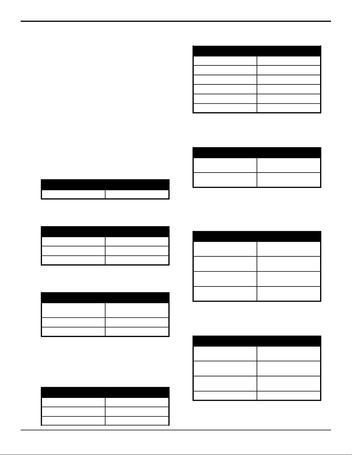
├ Side Panel
│ ├ Side Panel
│ ├ Contrast
│ └ Bright
├ Viewfinder Display
│ ├ Extender
│ ├ Shutter
│ ├ Zoom
│ ├ Focus
│ ├ Filter
│ ├ White Bal
│ ├ M. Gain
│ └ Iris
└ Viewfinder Zebra Marker
├ Zebra Type1
├ Level
├ Zebra Type2
├ High Level
├ Low Level
├ Indicator
├ Marker
└ Peak Hold
SettingsItem
OFF, ONSIDE 13:9
OFF, ONSIDE 14:9
OFF, ONSIDE 15:9
OFF, ONCROSS
OFF, ONBOX1
OFF, ONBOX2
Cross Setting
Press MENU and select VF > VF MARKER > CROSS
SET
SettingsItem
Viewfinder
Press MENU and select VF
SettingsItem
COLOR, Y, R, G, BVF OUT SEL
Viewfinder Detail
Press MENU and select VF > VF DETAIL
SettingsItem
OFF, ONVF DETAIL
-128 to 127DTL LEVEL
-128 to 127CRISP
Viewfinder Marker
Press MENU and select VF > VF MARKER
SettingsItem
USER SEL
USER1, USER2, USER3,
USER4
OFF, ONMARKER1 SW
OFF, ONMARKER2 SW
Marker 1/2 Selection
Press MENU and select VF > VF MARKER >
MARKER1 SEL
The Marker 2 Selection menu is identical to the Marker
1 Selection.
SettingsItem
OFF, ONCENTER MARK
OFF, ONSAFETY MARK
OFF, ONSIDE 4:3
position of cross-hair)
of cross-hair)
0 to 255H POSITION (horizontal
0 to 255V POSITION (vertical position
Box 1/2 Setting
Press MENU and select VF > VF MARKER > BOX1
SET
The Box 1 Setting menu is identical to the Box 2 Setting.
SettingsItem
position of the box)
of the box)
box)
box)
0 to 255H POSITION (horizontal
0 to 255V POSITION (vertical position
0 to 255H SIZE (horizontal size of the
0 to 255V SIZE (vertical size of the
Other Settings
Press MENU and select VF > VF MARKER > OTHER
SET
SettingsItem
CENTER MARK (type of
center mark)
action area)
action area)
TYPE1, TYPE2, TYPE3,
TYPE4
TYPE1, TYPE2, TYPE3SAFETY MARK (type of safe
80.0%, 90.0%, 92.5%, 95.0%SAFETY AREA (size of safe
0 to 100MARKER LEV
Side Panel
Press MENU and select VF > SIDE PANEL
ACID AC-H200-UCHR User Manual (v1.0) — Menu System • 25
Page 26
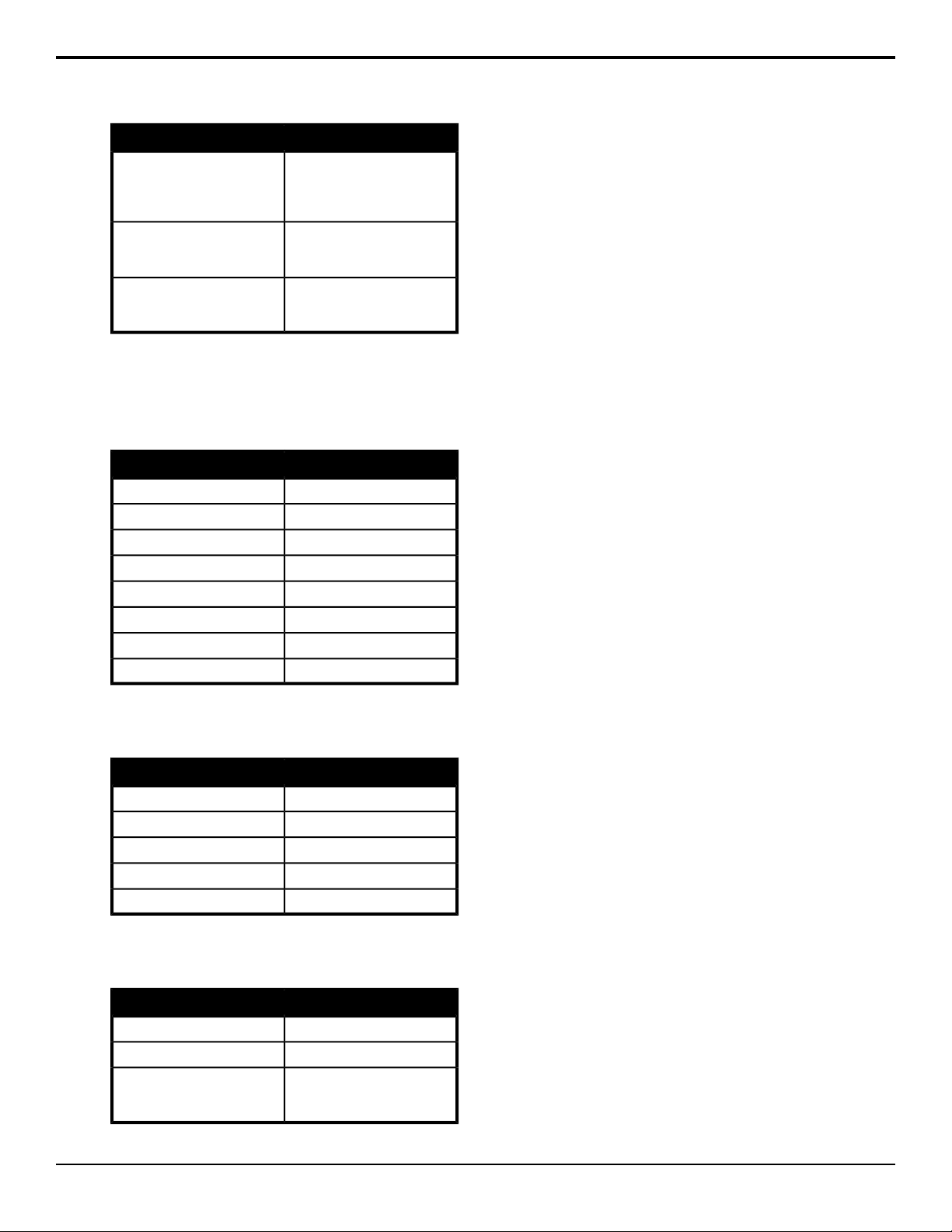
SettingsItem
image on monitor out - only
available when monitor is set
to 16:9)
pillarboxes on either side of the
image)
pillarboxes on either side of the
image)
OFF, 4:3, 13:9, 14:9, 15:9SIDE PANEL (aspect ratio of
1 to 5CONTRAST (contrast of
1 to 5BRIGHT (brightness of
Viewfinder Display
Press MENU and select VF > VF DISPLAY
This menu turns individual status items on or off for the
viewnder.
SettingsItem
OFF, ONEXTENDER
OFF, ONSHUTTER
OFF, ONZOOM
OFF, ONFOCUS
OFF, ONFILTER
OFF, ONWHITE BAL
OFF, ONM. GAIN
OFF, ONIRIS
Viewfinder Zebra Marker
Press MENU and select VF > VF ZEBRA
SettingsItem
OFF, ONZEBRA TYPE1
75% to 105%LEVEL
OFF, ONZEBRA TYPE2
55% to 100%HIGH LEVEL
50% to 99%LOW LEVEL
Focus Indicator
Press MENU and select VF > FOCUS IND
SettingsItem
OFF, ONINDICATOR (focus level bar)
OFF, ONMARKER (focus area marker)
focus level - displayed for 4
seconds)
OFF, ONPEAK HOLD (peak position of
26 • Menu System — ACID AC-H200-UCHR User Manual (v1.0)
Page 27

Serial Communications
The camera can be controlled over a serial connection
to the REMOTE1 port either by a remote control unit
or a device using standard RS-232.
The RS-232C/RU switch at the back of the camera must
be set to RU for communications with a remote control
unit, or RS-232C for communications with a device
using the RS-232C transmission standard.
ACID AC-H200-UCHR User Manual (v1.0) — Serial Communications • 27
Page 28

Troubleshooting
To Set the Video Format
If the video output format of the camera does not match
a format supported by your monitor, you can switch the
video output format using the menu buttons on the back
of the camera.
Disconnect power from the camera.
1.
Press and hold the menu buttons for the required
2.
video format and re-connect power to the camera.
•
1080p 59.94Hz — press FILTER + LEFT
•
1080i 59.94Hz — press FILTER + DOWN
•
720p 59.94Hz — press FILTER + RIGHT
•
1080p 50Hz — press MENU + LEFT
•
1080i 50Hz — press MENU + DOWN
•
720p 50Hz — press MENU + RIGHT
28 • Troubleshooting — ACID AC-H200-UCHR User Manual (v1.0)
Page 29
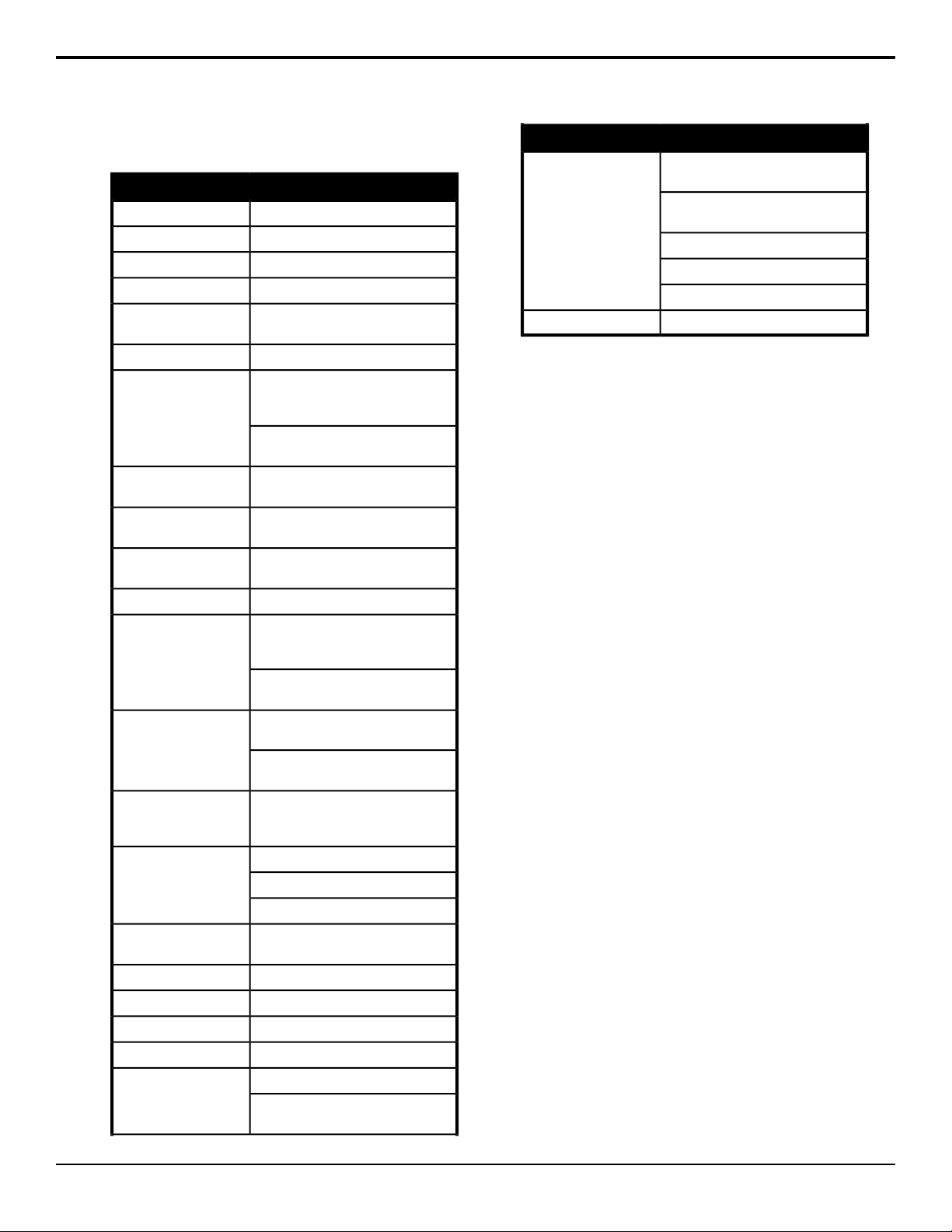
Specifications
SpecificationItem
2/3-inch MOSImage Sensor
2.6 Million (2,270×1,144)Total Pixels
1,920×1,080Effective Pixels
16:9 (HD/SD), 4:3 (SD) switchableAspect Ratio
TV Signal Format
Standard Sensitivity
Minimum Illumination
HD SNR
Optical Filter
Shutter (Preset Mode)
Shutter (Variable Scan
Mode)
Shutter (AES Mode)
Dimensions (W×H×L)
1080p 59.94Hz, 1080p 50Hz, 1080i
50Hz, 720p 59.94Hz
1100TVLHD Resolution
F12 at 2000lx, 3200K, 89.9%
reflectance (1080p 59.94Hz, 1080p
60Hz, 1080i 59.94Hz, 1080i 60Hz)
F13 at 2000lx, 3200K, 89.9%
reflectance (1080p 50Hz, 1080i 50Hz)
0.002lx at F1.4, 36dB Video Gain
+36dB frame accumulation mode
60dB (HD-SDI Output Decode Y
Channel)
Clear, 1/4ND, 1/16ND, 1/64ND (single
motorized filter wheel)
3200K, 4300K, 5600K, 6300K, 8000KECC Filter
1/100, 1/250, 1/500, 1/1000, 1/2000,
1/4000, 1/10000 second (59.94p,
59.94i, 60p, 60i)
1/60, 1/250, 1/500, 1/1000, 1/2000,
1/4000, 1/10000 second (50p, 50i)
1/60.15 to 1/9633, 0.03 to 1.07
second (59.94p, 59.94i, 60p, 60i)
1/50.17 to 1/11,250, 0.04 to 1.28
second (50p, 50i)
Automatic video level control by
shutter speed. AES controls amount
of light in equivalent to 4 lens F-stops.
L (low) -6dB, -3dB, 0dBGain Select
M (medium) 0 to +21dB, 3dB steps.
H (high) +3 to +36dB, 3dB steps.
99×105×155mm (excluding
protrusions)
-10 to 45°COperating Temperature
-20 to 60°CStorage Temperature
~18W (12VDC)Power Consumption
~1.3kg (2.9lbs)Weight
UC OUT — HD-SDI BNCInputs/Outputs
SDI OUT — HD-SDI BNC (Character
On/Off)
SpecificationItem
GL IN — BNC (Tri-Level or Black
Burst)
REMOTE1 — 4-Pin Multi (remote
control panel)
REMOTE2 — RJ-45 (remote control)
VF OUT — DB15 (viewfinder)
LENS — 12-pin Multi (lens control)
192.168.1.10Default IP Address
ACID AC-H200-UCHR User Manual (v1.0) — Specifications • 29
Page 30
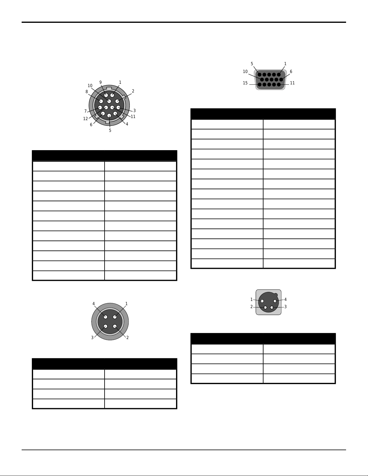
Ports
1
2
3
11
4
5
6
12
7
8
10
9
1
2
4
3
15
610
1115
1
2
4
3
LENS
Table 3: LENS Port Pinouts
SignalPin
AUX SW1
CALL TRG2
GND3
ENF AUTO4
IRIS CONTROL5
+12V6
IRIS POSITION7
IRIS A/R8
EXTENDED9
ZOOM POS10
F POS / L TX11
L RX12
VF OUT
Table 5: VF OUT Port Pinouts
SignalPin
Pr OUT1
Y OUT2
Pb OUT3
SYNC OUT4
VF DET5
GND6
Y SHIELD7
PEAKING CONT8
+12V OUT9
+12V OUT10
CPU DATA IN11
STRB1/R TALLY12
STRB2/G TALLY13
CPU DATA OUT14
CPU CLK/PEAKING SEL15
DC IN
REMOTE1
Table 6: DC IN Port Pinouts
SignalPin
Table 4: REMOTE1 Port Pinouts
SignalPin
+12V output1
SD input2
SD output3
SD GND4
30 • Ports — ACID AC-H200-UCHR User Manual (v1.0)
GND1
NC2
NC3
+12V In4
Page 31

Index
B
Back Focus 12
Black Balance 13
D
DashBoard, connecting 16
F
Filter 12
Flange Back Distance (FBD) 12
G
Grayscale Adjustment 14
I
IP Address 15
L
Lenses 12
M
Menu System 18
N
Network Settings 15
R
RS-232 27
S
Serial Communications. 27
Shutter Mode 14
V
Viewnder Display 17
W
White Balance 13
White Shading 12
ACID AC-H200-UCHR User Manual (v1.0) — Index • 31
 Loading...