


ICONIA Tab A100/A101
SERVICE GUIDE

Revision History
Refer to the table below for the updates made to this service guide.
Date Chapter Updates
Service guide files and updates are available on the ACER/CSD Website. For more
information, go to http://csd.acer.com.tw
without notice.
. The information in this guide is subject to change
Copyright
Copyright © 2011 by Acer Incorporated. All rights reserved. No part of this publication may be
reproduced, transmitted, transcribed, stored in a retrieval system, or translated into any
language or computer language, in any form or by any means, electronic, mechanical,
magnetic, optical, chemical, manual or otherwise, without the prior written permission of Acer
Incorporated.
Disclaimer
The information in this guide is subject to change without notice.
There are no representations or warranties, either expressed or implied, with respect to the
contents hereof and specifically disclaims any warranties of merchantability or fitness for any
particular purpose. The software described in this manual is sold or licensed "as is". Should
the programs prove defective following their pur ch as e, th e bu ye r (n ot the ma n uf ac tur e r,
distributor, or its dealer) assumes the entire cost of all necessary servicing, repair, and any
incidental or consequential damages resulting from any defect in the software.
ii

Conventions
WARNING:
!
CAUTION:
!
IMPORTANT:
+
IMPORTANT:
+
The following conventions are used in this manual:
Indicates a potential for personal injury.
Indicates a potential loss of data or damage to equipment.
Indicates information that is important to know for the proper completion of a
procedure, choice of an option, or completing a task.
Follow local regulations for battery and circuit board disposal. Batteries and
Circuit Boards >10 cm² have been highlighted with a yellow rectangle.
The following typographical conventions are used in this document:
Book titles, directory names, file names, path names, and program/process names are
shown in italics.
Example:
the DRS5 User's Guide
/usr/local/bin/fd
the /TPH15spool_M program
Computer output (text that represents information displayed on a computer screen,
such as menus, prompts, responses to input, and error messages) are shown in
constant width.
Example:
[01] The server has been stopped
User input (text that represents information entered by a computer user, such as
command names, option letters, and words) are shown in constant width bold.
Variables contained within user input are shown in angle brackets (< >).
Example:
At the prompt, type run <file name> -m
Keyboard keys are shown in bold italics.
Example:
After entering data, press Enter.
iii

General Information 0
This service guide provides all technical information relating to the basic configuration for Acer
global product offering. To better fit local market requirements and enhance product
competitiveness, your regional office may have decided to extend the functionality of a
machine (such as add-on cards, modems, or extra memory capabilities). These localized
features are not covered in this generic service guide. In such cases, contact your regional
offices or the responsible personnel/channel to provide further technical details.
When ordering FRU parts:
Check the most up-to-date information available on your regional Web or channel. If, for
whatever reason, a part number change is made, it may not be noted in this printed service
guide.
Acer-authorized Service Providers:
Your Acer office may have a differ ent part num ber code than those given in the FRU list in this
service guide. The list provided by your regional Acer office must be used to order FRU parts
for repair and service of customer machines.
iv

CHAPTER 1
Hardware Specifications
Features . . . . . . . . . . . . . . . . . . . . . . . . . . . . . . . . . . . . . . . . . . . .1-5
Form Factor. . . . . . . . . . . . . . . . . . . . . . . . . . . . . . . . . . . . . . . 1-5
CPU . . . . . . . . . . . . . . . . . . . . . . . . . . . . . . . . . . . . . . . . . . . . . 1-5
Memory. . . . . . . . . . . . . . . . . . . . . . . . . . . . . . . . . . . . . . . . . . 1-5
LCM . . . . . . . . . . . . . . . . . . . . . . . . . . . . . . . . . . . . . . . . . . . . . 1-5
Network . . . . . . . . . . . . . . . . . . . . . . . . . . . . . . . . . . . . . . . . . 1-5
GPS . . . . . . . . . . . . . . . . . . . . . . . . . . . . . . . . . . . . . . . . . . . . . 1-5
Camera . . . . . . . . . . . . . . . . . . . . . . . . . . . . . . . . . . . . . . . . . . 1-6
Connectivity . . . . . . . . . . . . . . . . . . . . . . . . . . . . . . . . . . . . . . 1-6
Input . . . . . . . . . . . . . . . . . . . . . . . . . . . . . . . . . . . . . . . . . . . . 1-6
Output. . . . . . . . . . . . . . . . . . . . . . . . . . . . . . . . . . . . . . . . . . . 1-6
Audio. . . . . . . . . . . . . . . . . . . . . . . . . . . . . . . . . . . . . . . . . . . . 1-7
Operation System. . . . . . . . . . . . . . . . . . . . . . . . . . . . . . . . . . 1-7
Dimension and Weight . . . . . . . . . . . . . . . . . . . . . . . . . . . . . 1-7
Expansion Slot . . . . . . . . . . . . . . . . . . . . . . . . . . . . . . . . . . . . 1-7
AC Adapter and Battery. . . . . . . . . . . . . . . . . . . . . . . . . . . . . 1-7
Environemental Requirements . . . . . . . . . . . . . . . . . . . . . . . 1-7
Others . . . . . . . . . . . . . . . . . . . . . . . . . . . . . . . . . . . . . . . . . . . 1-8
Accessories . . . . . . . . . . . . . . . . . . . . . . . . . . . . . . . . . . . . . . . 1-8
Notebook Tour. . . . . . . . . . . . . . . . . . . . . . . . . . . . . . . . . . . . . . . 1-9
Front View . . . . . . . . . . . . . . . . . . . . . . . . . . . . . . . . . . . . . . . 1-9
Rear View . . . . . . . . . . . . . . . . . . . . . . . . . . . . . . . . . . . . . . . . 1-10
Top View. . . . . . . . . . . . . . . . . . . . . . . . . . . . . . . . . . . . . . . . . 1-11
Left View. . . . . . . . . . . . . . . . . . . . . . . . . . . . . . . . . . . . . . . . . 1-12
Right View . . . . . . . . . . . . . . . . . . . . . . . . . . . . . . . . . . . . . . . 1-13
System Block Diagram . . . . . . . . . . . . . . . . . . . . . . . . . . . . . . . . . 1-15
Specification Tables . . . . . . . . . . . . . . . . . . . . . . . . . . . . . . . . . . . 1-16
Computer specifications . . . . . . . . . . . . . . . . . . . . . . . . . . . . . 1-16
System Board Major Chips . . . . . . . . . . . . . . . . . . . . . . . . . . . 1-17
Processor. . . . . . . . . . . . . . . . . . . . . . . . . . . . . . . . . . . . . . . . . 1-17
Processor Specifications . . . . . . . . . . . . . . . . . . . . . . . . . . . . . 1-18
System Memory. . . . . . . . . . . . . . . . . . . . . . . . . . . . . . . . . . . . 1-18
Video Interface (Integrated). . . . . . . . . . . . . . . . . . . . . . . . . . . 1-19
LAN Interface. . . . . . . . . . . . . . . . . . . . . . . . . . . . . . . . . . . . . . 1-20
LED 7.1”. . . . . . . . . . . . . . . . . . . . . . . . . . . . . . . . . . . . . . . . . . 1-22
Display Supported Resolution (LCD). . . . . . . . . . . . . . . . . . . . 1-23
Display Supported Resolution (GPU) . . . . . . . . . . . . . . . . . . . 1-23
Bluetooth Interface. . . . . . . . . . . . . . . . . . . . . . . . . . . . . . . . . . 1-23
Bluetooth Module. . . . . . . . . . . . . . . . . . . . . . . . . . . . . . . . . . . 1-24
Camera . . . . . . . . . . . . . . . . . . . . . . . . . . . . . . . . . . . . . . . . . . 1-24
Mini Card . . . . . . . . . . . . . . . . . . . . . . . . . . . . . . . . . . . . . . . . . 1-24
3G Card. . . . . . . . . . . . . . . . . . . . . . . . . . . . . . . . . . . . . . . . . . 1-24
v

Audio Codec and Amplifier . . . . . . . . . . . . . . . . . . . . . . . . . . . 1-24
Audio Interface. . . . . . . . . . . . . . . . . . . . . . . . . . . . . . . . . . . . . 1-25
Wireless Module 802.11b/g/n . . . . . . . . . . . . . . . . . . . . . . . . . 1-25
Battery . . . . . . . . . . . . . . . . . . . . . . . . . . . . . . . . . . . . . . . . . . . 1-25
VRAM . . . . . . . . . . . . . . . . . . . . . . . . . . . . . . . . . . . . . . . . . . . 1-25
USB Port . . . . . . . . . . . . . . . . . . . . . . . . . . . . . . . . . . . . . . . . . 1-26
HDMI Port . . . . . . . . . . . . . . . . . . . . . . . . . . . . . . . . . . . . . . . . 1-26
AC Adapter . . . . . . . . . . . . . . . . . . . . . . . . . . . . . . . . . . . . . . . 1-26
System Power Management . . . . . . . . . . . . . . . . . . . . . . . . . . 1-26
Card Reader . . . . . . . . . . . . . . . . . . . . . . . . . . . . . . . . . . . . . . 1-27
System LED Indicator . . . . . . . . . . . . . . . . . . . . . . . . . . . . . . . 1-27
System DMA Specification . . . . . . . . . . . . . . . . . . . . . . . . . . . 1-27
System Interrupt Specification (N/A) . . . . . . . . . . . . . . . . . . . . 1-28
System IO Address Map . . . . . . . . . . . . . . . . . . . . . . . . . . . . . 1-29
System I/O Address Specifications . . . . . . . . . . . . . . . . . . . . . 1-30
CHAPTER 2
Diagnostic Utilities
Introduction . . . . . . . . . . . . . . . . . . . . . . . . . . . . . . . . . . . . . . . . . 2-3
Diagnostic Tools. . . . . . . . . . . . . . . . . . . . . . . . . . . . . . . . . . . . . . 2-3
NGA EUU Installation Procedure. . . . . . . . . . . . . . . . . . . . . . . . . 2-3
Picasso Diagnostic Tool . . . . . . . . . . . . . . . . . . . . . . . . . . . . . . . . 2-11
CHAPTER 3
Maintenance Procedures
Introduction . . . . . . . . . . . . . . . . . . . . . . . . . . . . . . . . . . . . . . . . . 3-3
General Information . . . . . . . . . . . . . . . . . . . . . . . . . . . . . . . . . . 3-3
Recommended Equipment . . . . . . . . . . . . . . . . . . . . . . . . . . . . . 3-3
Maintenance Flowchart. . . . . . . . . . . . . . . . . . . . . . . . . . . . . . . . 3-4
Getting Started . . . . . . . . . . . . . . . . . . . . . . . . . . . . . . . . . . . . . . 3-5
SIM/Micro-SD Card Removal . . . . . . . . . . . . . . . . . . . . . . . . . 3-6
SIM/Micro-SD Card Installation . . . . . . . . . . . . . . . . . . . . . . . 3-7
Lower Case Removal . . . . . . . . . . . . . . . . . . . . . . . . . . . . . . . 3-8
Lower Case Installation . . . . . . . . . . . . . . . . . . . . . . . . . . . . . 3-15
Battery Removal . . . . . . . . . . . . . . . . . . . . . . . . . . . . . . . . . . . 3-16
Battery Installation. . . . . . . . . . . . . . . . . . . . . . . . . . . . . . . . . 3-18
3G Module Removal. . . . . . . . . . . . . . . . . . . . . . . . . . . . . . . . 3-19
3G Module Installation . . . . . . . . . . . . . . . . . . . . . . . . . . . . . 3-21
DC-In Cable Removal . . . . . . . . . . . . . . . . . . . . . . . . . . . . . . . 3-22
DC-In Cable Installation . . . . . . . . . . . . . . . . . . . . . . . . . . . . . 3-23
Speaker Module Removal . . . . . . . . . . . . . . . . . . . . . . . . . . . 3-24
Speakers Installation . . . . . . . . . . . . . . . . . . . . . . . . . . . . . . . 3-26
IO Board FPC Removal . . . . . . . . . . . . . . . . . . . . . . . . . . . . . . 3-27
IO Board FPC Installation . . . . . . . . . . . . . . . . . . . . . . . . . . . . 3-28
vi

IO Board Removal. . . . . . . . . . . . . . . . . . . . . . . . . . . . . . . . . . 3-29
IO Board Installation . . . . . . . . . . . . . . . . . . . . . . . . . . . . . . . 3-30
Microphone Module Removal. . . . . . . . . . . . . . . . . . . . . . . . 3-32
Microphone Module Installation. . . . . . . . . . . . . . . . . . . . . . 3-32
3G Antenna Removal . . . . . . . . . . . . . . . . . . . . . . . . . . . . . . . 3-33
3G Antenna Installation. . . . . . . . . . . . . . . . . . . . . . . . . . . . . 3-33
Light Sensor Module Removal. . . . . . . . . . . . . . . . . . . . . . . . 3-34
Light Sensor Module Installation . . . . . . . . . . . . . . . . . . . . . 3-34
GPS Antenna Removal . . . . . . . . . . . . . . . . . . . . . . . . . . . . . . 3-35
GPS Antenna Installation . . . . . . . . . . . . . . . . . . . . . . . . . . . . 3-35
Mainboard Removal. . . . . . . . . . . . . . . . . . . . . . . . . . . . . . . . 3-36
Mainboard Installation . . . . . . . . . . . . . . . . . . . . . . . . . . . . . 3-39
Rear CCD Board Removal. . . . . . . . . . . . . . . . . . . . . . . . . . . . 3-40
Rear CCD Board Installation . . . . . . . . . . . . . . . . . . . . . . . . . 3-42
WLAN Antenna Removal . . . . . . . . . . . . . . . . . . . . . . . . . . . . 3-43
WLAN Antenna Installation. . . . . . . . . . . . . . . . . . . . . . . . . . 3-43
Home Key Board Removal . . . . . . . . . . . . . . . . . . . . . . . . . . . 3-44
Home Key Board Installation. . . . . . . . . . . . . . . . . . . . . . . . . 3-45
CHAPTER 4
Troubleshooting
Introduction . . . . . . . . . . . . . . . . . . . . . . . . . . . . . . . . . . . . . . . . . 4-3
General Information . . . . . . . . . . . . . . . . . . . . . . . . . . . . . . . . . . 4-3
Power On Issues . . . . . . . . . . . . . . . . . . . . . . . . . . . . . . . . . . . 4-4
No Display Issues. . . . . . . . . . . . . . . . . . . . . . . . . . . . . . . . . . . 4-5
LCD Picture Failure . . . . . . . . . . . . . . . . . . . . . . . . . . . . . . . . . 4-6
Touch Screen Failure . . . . . . . . . . . . . . . . . . . . . . . . . . . . . . . 4-7
Internal Speaker Failure. . . . . . . . . . . . . . . . . . . . . . . . . . . . . 4-8
Internal Microphone Failure . . . . . . . . . . . . . . . . . . . . . . . . . 4-9
USB Failure/mini-USB Failure . . . . . . . . . . . . . . . . . . . . . . . . . 4-10
Front Camera Failure . . . . . . . . . . . . . . . . . . . . . . . . . . . . . . . 4-11
Back Camera Failure. . . . . . . . . . . . . . . . . . . . . . . . . . . . . . . . 4-12
P-Sensor Failure . . . . . . . . . . . . . . . . . . . . . . . . . . . . . . . . . . . 4-13
3G Function Failure . . . . . . . . . . . . . . . . . . . . . . . . . . . . . . . . 4-14
Wireless Function Test Failure . . . . . . . . . . . . . . . . . . . . . . . . 4-15
GPS Function Test Failure (Wi-Fi SKU). . . . . . . . . . . . . . . . . . 4-16
GPS Function Test Failure (3G SKU). . . . . . . . . . . . . . . . . . . . 4-17
Docking Station Test Failure . . . . . . . . . . . . . . . . . . . . . . . . . 4-18
Other Functions Failure . . . . . . . . . . . . . . . . . . . . . . . . . . . . . 4-19
vii

CHAPTER 5
Jumper and Connector Locations
Mainboard Top . . . . . . . . . . . . . . . . . . . . . . . . . . . . . . . . . . . . . . 5-3
Mainboard Bottom . . . . . . . . . . . . . . . . . . . . . . . . . . . . . . . . . . . 5-4
CHAPTER 6
Field Replaceable Unit List
Exploded Diagrams . . . . . . . . . . . . . . . . . . . . . . . . . . . . . . . . . . . 6-4
Main Assembly . . . . . . . . . . . . . . . . . . . . . . . . . . . . . . . . . . . . 6-4
FRU List . . . . . . . . . . . . . . . . . . . . . . . . . . . . . . . . . . . . . . . . . . . . . 6-6
Screw List . . . . . . . . . . . . . . . . . . . . . . . . . . . . . . . . . . . . . . . . . . . 6-9
CHAPTER 7
Model Definition and Configuration
A100 . . . . . . . . . . . . . . . . . . . . . . . . . . . . . . . . . . . . . . . . . . . . . . . 7-3
A101 . . . . . . . . . . . . . . . . . . . . . . . . . . . . . . . . . . . . . . . . . . . . . . . 7-14
CHAPTER 8
Test Compatible Components
Android OS Environment Test. . . . . . . . . . . . . . . . . . . . . . . . . . . 8-4
A100/A101. . . . . . . . . . . . . . . . . . . . . . . . . . . . . . . . . . . . . . . . 8-4
CHAPTER 9
Online Support Information
Introduction . . . . . . . . . . . . . . . . . . . . . . . . . . . . . . . . . . . . . . . . . 9-3
viii

CHAPTER 1
Hardware Specifications

Features . . . . . . . . . . . . . . . . . . . . . . . . . . . . . . . . . . . . . . . . . . . . 1-5
Form Factor. . . . . . . . . . . . . . . . . . . . . . . . . . . . . . . . . . . . . . . 1-5
CPU . . . . . . . . . . . . . . . . . . . . . . . . . . . . . . . . . . . . . . . . . . . . . 1-5
Memory. . . . . . . . . . . . . . . . . . . . . . . . . . . . . . . . . . . . . . . . . . 1-5
LCM . . . . . . . . . . . . . . . . . . . . . . . . . . . . . . . . . . . . . . . . . . . . . 1-5
Network . . . . . . . . . . . . . . . . . . . . . . . . . . . . . . . . . . . . . . . . . 1-5
GPS . . . . . . . . . . . . . . . . . . . . . . . . . . . . . . . . . . . . . . . . . . . . . 1-5
Camera . . . . . . . . . . . . . . . . . . . . . . . . . . . . . . . . . . . . . . . . . . 1-6
Connectivity . . . . . . . . . . . . . . . . . . . . . . . . . . . . . . . . . . . . . . 1-6
Input . . . . . . . . . . . . . . . . . . . . . . . . . . . . . . . . . . . . . . . . . . . . 1-6
Output. . . . . . . . . . . . . . . . . . . . . . . . . . . . . . . . . . . . . . . . . . . 1-6
Audio. . . . . . . . . . . . . . . . . . . . . . . . . . . . . . . . . . . . . . . . . . . . 1-7
Operation System. . . . . . . . . . . . . . . . . . . . . . . . . . . . . . . . . . 1-7
Dimension and Weight . . . . . . . . . . . . . . . . . . . . . . . . . . . . . 1-7
Expansion Slot . . . . . . . . . . . . . . . . . . . . . . . . . . . . . . . . . . . . 1-7
AC Adapter and Battery. . . . . . . . . . . . . . . . . . . . . . . . . . . . . 1-7
Environemental Requirements . . . . . . . . . . . . . . . . . . . . . . . 1-7
Others . . . . . . . . . . . . . . . . . . . . . . . . . . . . . . . . . . . . . . . . . . . 1-8
Accessories . . . . . . . . . . . . . . . . . . . . . . . . . . . . . . . . . . . . . . . 1-8
Notebook Tour. . . . . . . . . . . . . . . . . . . . . . . . . . . . . . . . . . . . . . . 1-9
Front View . . . . . . . . . . . . . . . . . . . . . . . . . . . . . . . . . . . . . . . 1-9
Rear View . . . . . . . . . . . . . . . . . . . . . . . . . . . . . . . . . . . . . . . . 1-10
Top View. . . . . . . . . . . . . . . . . . . . . . . . . . . . . . . . . . . . . . . . . 1-11
Left View. . . . . . . . . . . . . . . . . . . . . . . . . . . . . . . . . . . . . . . . . 1-12
Right View . . . . . . . . . . . . . . . . . . . . . . . . . . . . . . . . . . . . . . . 1-13
System Block Diagram . . . . . . . . . . . . . . . . . . . . . . . . . . . . . . . . . 1-15
Specification Tables . . . . . . . . . . . . . . . . . . . . . . . . . . . . . . . . . . . 1-16
Computer specifications . . . . . . . . . . . . . . . . . . . . . . . . . . . . . 1-16
Processor. . . . . . . . . . . . . . . . . . . . . . . . . . . . . . . . . . . . . . . . . 1-17
Processor Specifications . . . . . . . . . . . . . . . . . . . . . . . . . . . . . 1-18
System Memory. . . . . . . . . . . . . . . . . . . . . . . . . . . . . . . . . . . . 1-18
Video Interface (Integrated). . . . . . . . . . . . . . . . . . . . . . . . . . . 1-19
LAN Interface. . . . . . . . . . . . . . . . . . . . . . . . . . . . . . . . . . . . . . 1-20
LED 7.1”. . . . . . . . . . . . . . . . . . . . . . . . . . . . . . . . . . . . . . . . . . 1-22
Display Supported Resolution (LCD). . . . . . . . . . . . . . . . . . . . 1-23
Display Supported Resolution (GPU) . . . . . . . . . . . . . . . . . . . 1-23
Bluetooth Interface. . . . . . . . . . . . . . . . . . . . . . . . . . . . . . . . . . 1-23
Camera . . . . . . . . . . . . . . . . . . . . . . . . . . . . . . . . . . . . . . . . . . 1-24
Mini Card . . . . . . . . . . . . . . . . . . . . . . . . . . . . . . . . . . . . . . . . . 1-24
3G Card. . . . . . . . . . . . . . . . . . . . . . . . . . . . . . . . . . . . . . . . . . 1-24
Audio Codec and Amplifier . . . . . . . . . . . . . . . . . . . . . . . . . . . 1-24
Audio Interface. . . . . . . . . . . . . . . . . . . . . . . . . . . . . . . . . . . . . 1-25
Wireless Module 802.11b/g/n . . . . . . . . . . . . . . . . . . . . . . . . . 1-25
Battery . . . . . . . . . . . . . . . . . . . . . . . . . . . . . . . . . . . . . . . . . . . 1-25
VRAM . . . . . . . . . . . . . . . . . . . . . . . . . . . . . . . . . . . . . . . . . . . 1-25
HDMI Port . . . . . . . . . . . . . . . . . . . . . . . . . . . . . . . . . . . . . . . . 1-26
1-2

AC Adapter . . . . . . . . . . . . . . . . . . . . . . . . . . . . . . . . . . . . . . . 1-26
System Power Management . . . . . . . . . . . . . . . . . . . . . . . . . . 1-26
Card Reader . . . . . . . . . . . . . . . . . . . . . . . . . . . . . . . . . . . . . . 1-27
System LED Indicator . . . . . . . . . . . . . . . . . . . . . . . . . . . . . . . 1-27
System DMA Specification . . . . . . . . . . . . . . . . . . . . . . . . . . . 1-27
1-3

1-4

Hardware Specifications and Configurations
Features 0
The following is a summary of the computer’s many features:
Form Factor 0
7" Tablet
CPU 0
Tegra 250 Dual cortex A9, 1GHz
GPU Ultra Low Power GeForce
Memory 0
RAM: LP DDR2 up to 1GB, POP type, discrete on board
eMMC: 8G(default)
LCM 0
7" WSVGA LCM (1024*600 CMI and CPT)
View angle 70 degree at least at each 4 site
LVDS interface
®
GPU
Network 0
2G: GSM/GPRS/EDGE 850MHz / 900MHz / 1800Mhz / 1900Mhz
3G Module Erisson F5521gw (with GPS/AGPS)
UMTS /WCDMA 1, 2, 5, 8 2100/1900/850/900
HSPA+ : HSDPA up to 21Mbps/ HSUPA up to 5.76Mbps
GSM/GPRS/EDGE 850MHz / 900MHz / 1800Mhz / 1900Mhz
GPS 0
WIFI SKU : Broadcom 4751 - stand alone, no AGPS
3G SKU : on 3G module
Cold-start TTFF: < 50sec
Hardware Specifications and Configurations 1-5

Camera 0
Rear camera: 5M Camera with Auto focus (Chicony / Aptina 5140)
with flash lights (single LED)
Detail spec
Focus speed < 0.7 sec at 5 lux
with flash lights (single LED)
Min exposure time: 1/15 sec
720p H.264 @ 30fps/14Mbps recording
VGA H.264 @ 60fps/7Mbps recording
Min Recording FPS: 15fps @ 30 lux
Digital Image Stabilization
Fast shots in 5MP mode
Fast camera ready time (2 sec from camera key press to ready-to-capture state)
Front camera : 2M FF
Connectivity 0
BRCM 4329 Wi-Fi IEEE 802.11b/g/n and Bluetooth
USB
Micro USB 2.0 support
®
2.1(extendable to 3.0)
Input 0
Capacitive Multi-Touch Screen (5 4 points)(control IC: Cypress)
Function buttons
Side (mechanical key):
Volume Up, Volume Down, screen lock
Power :with back light-white/orange , Lighting Behaviors V1.0
Android Home touch key
Sensors
G-Sensor
Capacitive Sensor(for SAR issue)
E-Compass
L Sensor
Gyro-meter
mini SIM (Support MM-SIM) push-push type
Output 0
HDMI D-type (support Dual Display)
1-6 Hardware Specifications and Configurations

Audio 0
Single analog Microphone (Noise / echo cancellation)
Dual Speaker: above 1.0W/pcs, chamber size is 1cc around each
3.5mm Audio Jack 4ring (with Mic)
Dolby
Operation System 0
Gingerbread
Dimension and Weight 0
Dimensions
195 (L) x 117 (W) x 13.1 (H) mm
Weight
WIFI SKU < 410g(target)
3G SKU < 430g(target)
Expansion Slot 0
MicroSD memory card up to 32G (SDHC 2.0 compatible)
AC Adapter and Battery 0
Battery
Rechargeable Lithium-ion or polymer battery (Sony 454261 Polymer cell / Sanyo
484462 prismatic cell)
Capacity: 11.3W (1530 mAh cell, 2S1P)
Battery-life (TBD)
Video playback: 5 hours when play 720P H.264 video playback on system (not
streaming, Wifi/3G/BT off, 50% brightness )
Stand-by: 250 hours(LCD off)
Web surfing : WIFI SKU up to 5 hours, 3G SKU up to 4 hours
Youtube playback 720p video for 5.2h o ur s via WIF I; 3. 6 ho ur s v ia 3G
Charging time: 1 hour to reach 50% (when in sleep mode)
AC Adapter
Voltage range/frequency: 100 ~ 240V AC, 50/60 Hz
DC output: 12V and 1.5 A, 18W
Environemental Requirements 0
Rohs compliance
WEEE compliance
Hologen free, at least PVC free
SMT Green process
Hardware Specifications and Configurations 1-7

Others 0
Reset hole
Docking support (HDMI, power, audio)
Accessories 0
In Box
Charger + Plug
QSG
Optional
Earphone
Micro SD Card
Docking + IR remote
Pouch
1-8 Hardware Specifications and Configurations
Notebook Tour 0
1
2
3
4
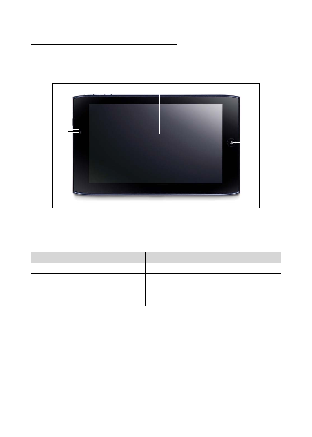
Front View 0
Figure 1-1. Front View
Table 1-1. Front View
# Icon Item Description
1 Front Camera 2M Pixel CCD
2 Light Sensor
3 Touch Window
4 Home Button
Hardware Specifications and Configurations 1-9
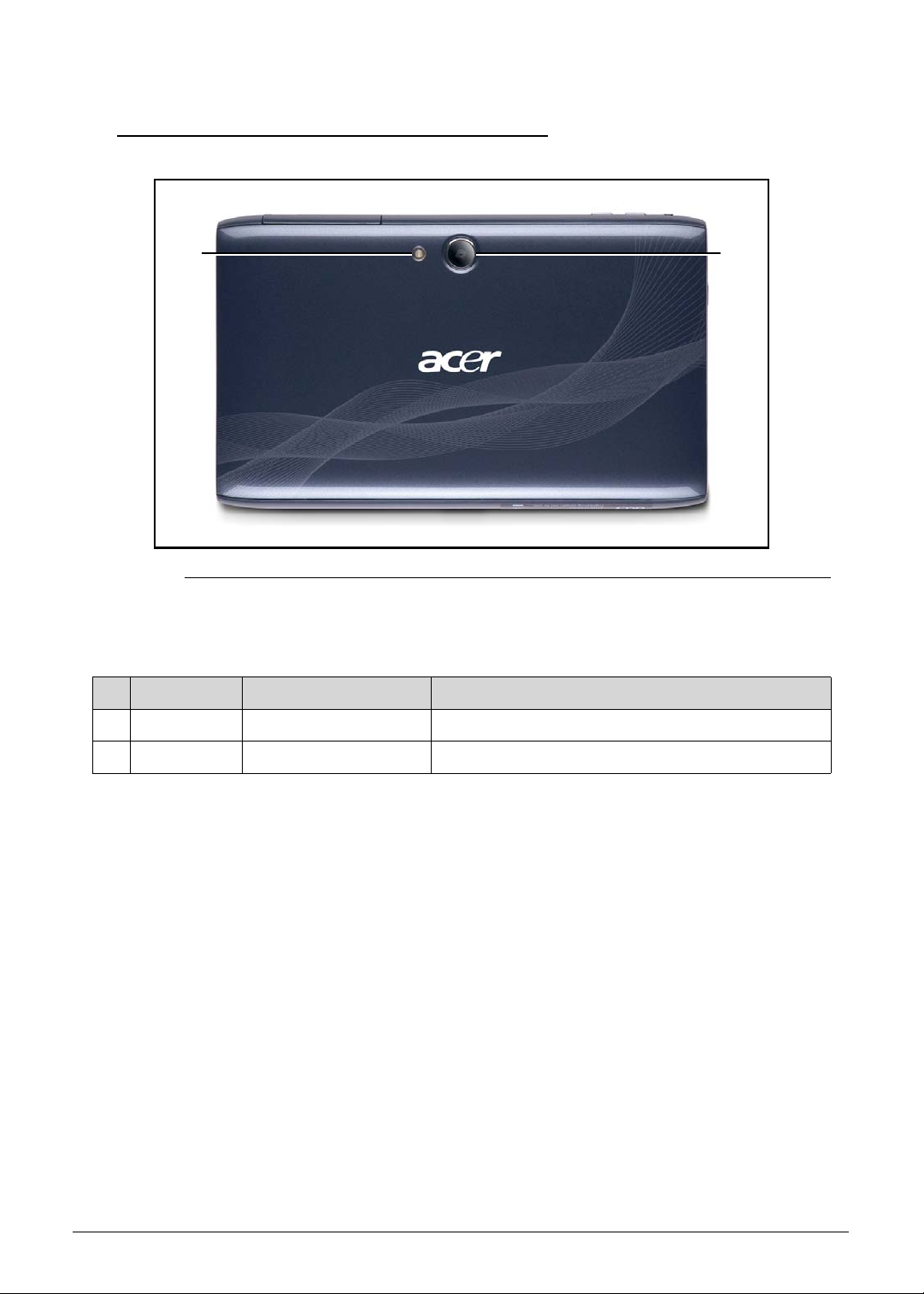
Rear View 0
2
1
Figure 1-2. Front View
Table 1-2. Front View
# Icon Item Description
1 Rear Camera 5M Pixel CCD
2LED Flash
1-10 Hardware Specifications and Configurations
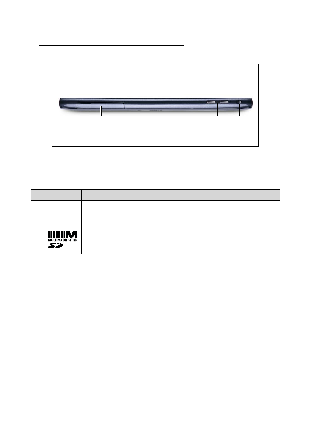
Top View 0
12
3
Figure 1-3. Top View
Table 1-3. Top View
# Icon Item Description
1 Rotation Lock switch Screen Rotation Control Lock switch
2 Volume Control Key
3 Card Slots SIM*/microSD card slot
(* only for A101)
Hardware Specifications and Configurations 1-11
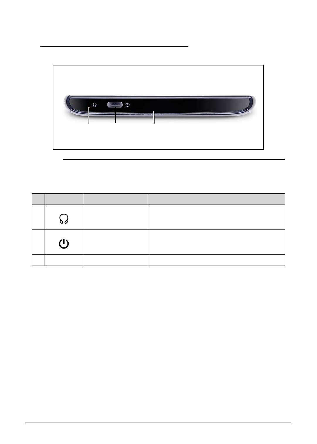
Left View 0
1 2 3
Figure 1-4. Left View
Table 1-4. Left View
# Icon Item Description
1 Headphones/ S peaker
Jack
2 Power/ Resume
Button
3 Microphone
Power on machine or resume from sleep mode.
1-12 Hardware Specifications and Configurations
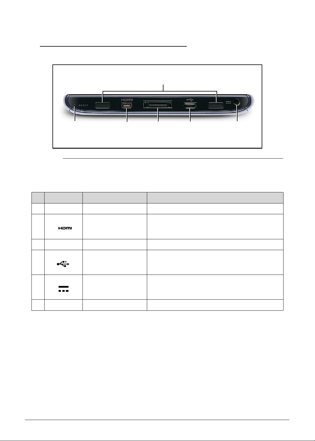
Right View 0
1
6
2
3
4
5
Figure 1-5. Right View
Table 1-5. Right View
# Icon Item Description
1 Reset Button
2 micro-HDMI Port Micro (Type D) HDMI port.
3 Docking Port
4 micro-USB Connector
5 DC-IN Jack
6 Speakers
Hardware Specifications and Configurations 1-13
Bottom View (N/A) 0
Figure 1-6. Bottom View
Table 1-6. Bottom View
# Icon Item Description
1-14 Hardware Specifications and Configurations
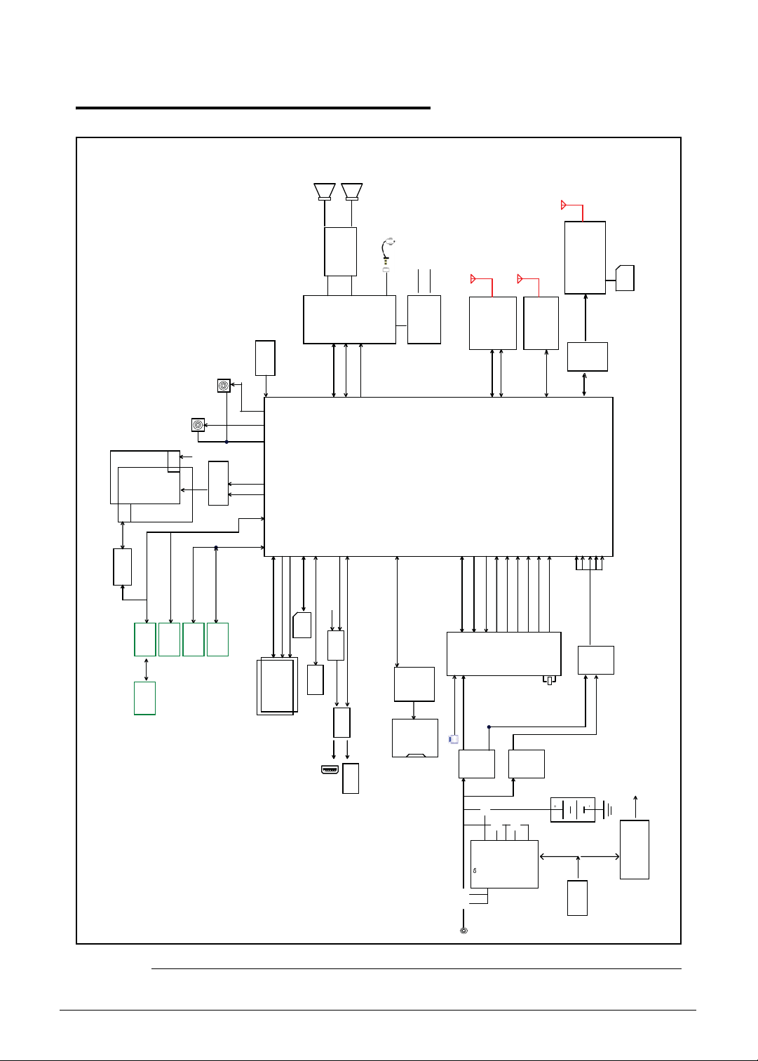
System Block Diagram 0
Level Shift
TP
Control
(1.8V/3.3V)
7"
1024*600
CMI
GEN1_I2C
Gyro Sensor
Invensense
MPU-3050
IME_I2C
KXTF9-4100
G-Sensor
(AT070TNA2)
Light Sensor
Backlight
GEN1_I2C
AL3000A
5M
Driver
Capacitive
(Chicony CJAA525)
Touch Panel
PWR_I2C
NCT1008
Temp Sensor
2M
(Chicony CBFA152)
LVDS Bridge
PWR_I2C
E-Compass
CAM_I2C
SN75LVDS83B
AKM8975
SPEAKERx2 1W
SPK_R
SPK_L
ALC105
Audio Am p
LOP/N
Earphone
(Option)
INT MIC*1
EXT MIC*1
BT/WLAN Antenna
(Option)
GPS Antenna
ROP/N
HPOUTR/L
AzureWave
CODEC
Wolfson
Debug
Test Point
JTAG
MIPI
(CSIB)
MIPI
(CSIA)
CAM_I2C
(1.8V)
LCDC
(RGB)
SPI
GEN1_I2C
(1.8V)
SDIO3(3.3V)
CS0
Memory I/F
PWR_I2C(1.8V)
SDIO4(1.8V)
CS1
NVIDIA Tegra250(T20)
WM8903
I2S
(23mm x 23mm)
GPIO
MCLK
Fortemedia
FM2018
GEN1_I2C
DAP_MCLK1
FCBGA
HS USB D+/D-(USB1)/ Client
HDMI
HS USB D+/D-(USB3)/ Host
AW-NH611
PWR_I2C(1.8V)
CPU_PWR_REQ
CORE_PWR_REQ
BCM4751
SDIO
UART
BT
WLAN
UART3
(1.8V)SDIO1
VDD_RTC
CLK_32K_IN
PWR_INT_N
SYS_RESET_N
(Option)
3G Modem Antenna
3G Modem Module
UART
SIM
with HSPA+
(MSM6290/U335/F3607gw)
USB D+/D-(USB2)
ULPI PHY
SMSC
USB3315
GPS
UART2
VDD_CPU
VDD_CORE
ULPI_Reset
DAP_MCLK2
ULPI DATA(USB2)
VDDIO_SDIO
VDDIO_UART
VDDIO_DDR
VDD_NAND
VDD_LCD
VDD_AUDIO
VDD_BB
PWR_I2C
5V
Micro SD
Slot
Power Switch
(Current Limit)
eMMC 4.4
4G/8G/16G/32G
LPDDR POP 512MB/1GB
Client
Signal Switch
SM0_EN
SM1_EN
32K_OUT
SCLK/SDAT
PMIC
TPS658621
VIN
SM1
SM0
nINT
LDO2
nRESET
LDO
32KHz
Signal Switch
PS8122
Micro- USB
CNN
Dock
+5VALW
+3VALWS
T20
+
-
System input
GND
HIDRV
BTST
LODRV
nBATDRV
Charger IC
BQ24725
nACDRV
SMBUS
ENE KBC
KB930
Android HomeKey
Touch-key
ENE 3534
Adapter in(12V/1.5A)18W
Figure 1-7. System Block Diagram
Hardware Specifications and Configurations 1-15
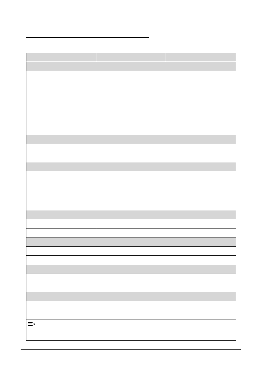
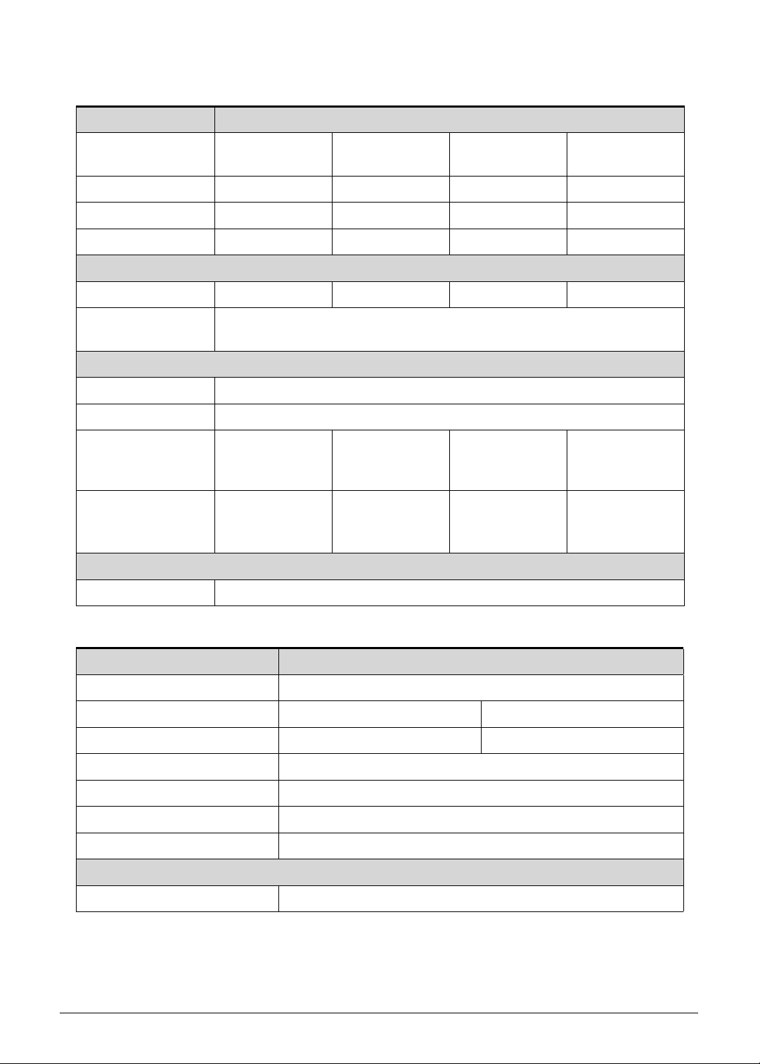
Specification Tables 0
NOTE:
Computer specifications
Item Metric Imperial
Dimensions
Length 195.0 mm 7.68 inch
Width 117 mm 4.61 in
Height
(front to rear)
Weight (equipped with optical
drive, flash drive, and battery)
Weight (equipped with optical
drive, flash drive, and battery)
Input power
Operating voltage 12.0 V dc @ 1.5 A - 18 W
Operating current 1.5A
Temperature
Operating (not writing to
optical disc)
Operating (writing to optical
disc)
Nonoperating -20°C to 60°C -4°F to 140°F
Relative humidity
Operating 10% to 90%
Nonoperating 5% to 95%
13.1mm 0.52in
~405 g 0.9 lbs
Build-in battery Build-in battery
0°C to 50°C 32°F to 122°F
0°C to 50°C 32°F to 122°F
Maximum altitude (unpressurized)
Operating -15 m to 3,048 m -50 ft to 10,000 ft
Nonoperating -15 m to 12,192 m -50 ft to 40,000 ft
Shock
Operating 125 g, 2 ms, half-sine
Nonoperating 200 g, 2 ms, half-sine
Random vibration
Operating 0.75 g zero-to-peak, 10 Hz to 500 Hz, 0.25 oct/min sweep rate
Nonoperating 1.50 g zero-to-peak, 10 Hz to 500 Hz, 0.25 oct/min sweep rate
Applicable product safety standards specify thermal limits for plastic surfaces. The comp uter
operates well within this range of temperatures.
1-16 Hardware Specifications and Configurations
System Board Major Chips
Item Specification
Core logic Tegra 250 Dual cortex A9, 1GHz
VGA Integrated with CPU
LAN N/A
USB 2.0 Controller integrated with CPU
Super I/O controller Integrated with CPU
Bluetooth Broadcom BCM4329
Wireless Broadcom BCM4329
PCMCIA N/A
Audio codec Wolfson WM8903
Card reader SD card controller integrated with CPU
LVDS transmitter SN75LVDS83B
PMU TI TI TPS658621C
LDDR2 Elpida EDB8132B2PB 1GB
ULPI Phy for USB SMSC USB3315
GPS Broadcom BCM4751
TOUCH controller Cypress
eMMC 8GB
CAMERA
Chicony CJAA525: 5M pixel
Chicony CJFB21120003350LH: 2M pixel
Thermal Sensor Onsemi NTC1008
Battery Charger TI BQ24617
Compass Asahi Kasei AKM8975C
Gyro Invensense MPU-3050
ALS/Proximity Lite On AL3000A / AZOTEK IQS128
Processor
Item Specification
CPU type
Dual-core ARM
®
Coretex-A9 MPcore Processor
CPU package 23 x 23 FCBGA
Core Logic CPU: nVidia Tegra T20
Chipset Integrated with CPU
Hardware Specifications and Configurations 1-17
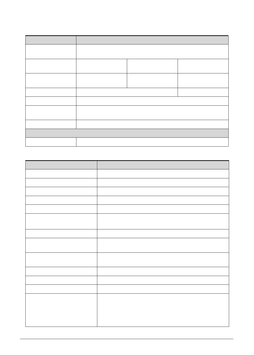
Processor Specifications
Item CPU Speed
(GHz)
T20 1 GHz 2 Cores 64 bits 40 nm 1 MB 23x23
CPU Fan True Value Table (N/A)
CPU Temperature Fan Speed (RPM) SPL Spec (dBA)
60
70
80
90
100
System Memory
Item Specification
Memory controller Build in CPU
Cores/
Threads
Bus
Speed
(FSB/
DMI/QBI)
Mfg
Tech
(nm)
Cache
Size
Package Voltage
FCBGA
1.0-1.2V
Memory size 1GB LPDDRII
DIMM socket number N/A
Supports memory size per socket N/A
Supports maximum memory size N/A
Supports DIMM type N/A
Supports DIMM Speed N/A
Support DIMM voltage N/A
Supports DIMM package N/A
1-18 Hardware Specifications and Configurations
Memory Combinations (N/A)
Slot 1 (MB) Slot 2 (MB) Total Memory (MB)
Video Interface (Integrated)
Item Specification
Chipset
Package
Interface
Compatibility
Sampling rate
Hardware Specifications and Configurations 1-19
BIOS (N/A)
Item Specification
BIOS vendor
BIOS Version
BIOS ROM type
BIOS ROM size
Features
LAN Interface
Item Specification
LAN Chipset N/A (No LAN Port)
LAN connector type N/A (No LAN Port)
LAN connector location N/A (No LAN Port)
Features UMTS /WCDMA a. 3G dual band / b. 3G qual band / c. LTE
n HSDPA up to 7.2Mbps/ HSUPA up to 5.76Mbps
n GSM/GPRS/EDGE 850MHz / 900MHz / 1800Mhz / 1900Mhz
Keyboard (N/A)
Item Specification
Type
Total number of keypads
Windows logo key
Internal & external keyboard
work simultaneously
Features
1-20 Hardware Specifications and Configurations
Hard Disk Drive (AVL components) (N/A)
Item Specification
Vendor & Model
Name
Capacity (GB)
Bytes per sector
Data heads
Drive Format
Disks
Spindle speed
(RPM)
Performance Specifications
Buffer size
Interface
Fast data transfer
rate (Mbits / sec,
max)
Media data transfer
rate
(Mbytes/sec max)
DC Power Requirements
Voltage tolerance
Super-Multi Drive (N/A)
Item Specification
Vendor & Model name
Performance Specification
Transfer rate (KB/sec)
Buffer Memory
Interface
Applicable disc format
Loading mechanism
Power Requirement
Input Voltage
Hardware Specifications and Configurations 1-21
BD Drive (N/A)
Items Specifications
Vendor & Model
name
Performance
Specification
Transfer rate
(KB/sec)
Buffer Memory
Interface
Applicable disc
format
Loading mechanism
Power Requirement
Input Voltage
LED 7.1”
Item Specification
Vendor/Model name CMI/AT070TNA2
Screen Diagonal (mm) 255.52 mm
Active Area (mm) 222.72 mm x 125.28 mm
Display resolution (pixels) 1024 x 3(RGB) x 600
Pixel Pitch (mm) 0.2175mm × 0.2088 mm
Typical White Luminance
2
(cd/m
) also called Brightness
200 cd/m
2
Contrast Ratio 400 min / 500 type
Response Time (Optical Rise
8 ms / 12 ms
Time/Fall Time) msec
Typical Power Consumption
2.17 W
(watt)
Weight (without inverter) 190g max
Physical Size (mm) 235.5 mm x 143.5 mm x 5.2mm max
Electrical Interface 1 channel LVDS
Viewing Angle (degree)
70 (Right) / 70 (Left) / 60 (Upper) / 60 (Lower) min.
Horizontal (Right) CR = 10
(Left)
Vertical (Upper) CR = 10
(Lower)
1-22 Hardware Specifications and Configurations

LCD Inverter (N/A)
Item Specification
Vendor & Model name
Brightness conditions
Input voltage (v)
Input current (mA)
Output voltage (V, RMS)
Output current (mA, RMS)
Output voltage frequency
(KHz)
Display Supported Resolution (LCD)
Resolution 16 bits 32 bits Intel NVIDIA ATI
1024x 3(RGB) x 600 X X X V X
Graphics Controller (N/A)
Item Specification
VGA Chip
Supports
Display Supported Resolution (GPU)
Resolution 16 bits 32 bits Intel NVDIA ATI
1024x 3(RGB) x 600 X X X V X
Bluetooth Interface
Item Specifications
Chipset Aruzewave AW-NH611 (SiP module)
Data throughput
TX 1.2Mbits/sec
RX 1.2Mbits/sec
Protocol 2.1+EDR
Interface SiP
Connector type SiP
Supported protocol A2DP
Hardware Specifications and Configurations 1-23

Bluetooth Module
Item Specifications
Controller Azurewave AW-NH611 - Broadcom BCM43 29 SoC
Features
Fully support BT 2.1 +EDR
UART Interface
Camera
Item Specification
Vendor and Model Chicony CJAA525
Type 5M
Mini Card
Item Specification
Number supported 1
Features 1 mini card slot (for WWAN module)
3G Card
Item Specification
Features 3G Module with Ericsson 5521gw
Audio Codec and Amplifier
Item Specification
Audio Controller Audio codec: Wolfson WM8903
Features
4.5mW Power consumption for DAC to headphone playback
DAC SNR 96dB typical , THD -86dB typical
ADC SNR 92dB typical , THD -80dB typical
Control sequencer for pop minimized start-up and shut-down
Single register write for default start-up sequ ence
Stereo digital microphone input
3 single ended inputs per stereo channel
2 pseudo differential inputs per stereo channel
1 fully differential mic inputs per stereo channel
Digital Dynamic Range Controller
Digital sidetone mixing
Ground-referenced headphone driver
Ground-referenced line input
Stereo differential line driver for direct interface to WM9001
speaker driver
40-pin5x5mm QFN package
Amplifier N/A
Features N/A
1-24 Hardware Specifications and Configurations

Audio Interface
Item Specification
Audio Controller Wolfson WM8903
Audio onboard or optional On board
Mono or Stereo Stereo
Resolution Support 24bit
Compatibility I2S audio Interface
Sampling rate Sample rate up to 44.1KHz
Internal microphone Yes
Internal speaker/quantity Yes/(1W speakers x2)
Wireless Module 802.11b/g/n
Item Specification
Chipset Azurewave AW-NH611 - Broadcom BCM4329 SoC
Data throughput
802.11b/g: 11~54 Mbps
802.11n: MCS 0-7
Protocol IEEE 802.11b/g/n
Interface SDIO/SPI interface.
Battery
Item Specification
Vendor & Model name SANYO BAT-711
Battery Type Li-ion
Pack capacity 1530 mAh
Number of battery cell 2
Package configuration 2S1P
VRAM
Item Specification
Chipset T20 UMA architecture
Memory size Share 16 ~ 256MB
Interface LPDDR2
Hardware Specifications and Configurations 1-25

USB Port
Item Specification
USB compliance level USB2.0
Protocol EHCI
Number of USB port(s) 1
Location one at the right side
Output Current
HDMI Port
Item Specification
Compliance level HDMI1.3a
Data throughput Up to 16.7 million colors
Number of HDMI port(s) 1
Location one at the right side
AC Adapter
Item Specification
Input rating 18W
Maximum input AC current 0.5A(RMS) at 100Vac
Inrush current 60A Max. @230Vac
Efficiency Refer to EPS 2.0 standard level V
System Power Management
Item Specification
Mech. Off (G3) Only EC working.
Soft Off (G2/S5) Only EC working.
Working (G0/S0) Individual devices such as the CPU and eMMC may be power
managed in this state.
Suspend to RAM (S3)
CPU suspend
Audio Power Down
eMMC Power Down
LCD power off
MIC power off
Save to Disk (S4) N/A
1-26 Hardware Specifications and Configurations

Card Reader
Item Specification
Chipset Embedded in T20 SOC.
Package FCBGA -664 23 X 23
Maximum supported size SD: 32G
Features Storage cards with adapter: mirco SD™
System LED Indicator
Item Specification
Lock N/A
System state
White color : Flash on booting
White color and amber color off : System off / suspend
Amber color : Battery in charging
HDD access state N/A
Wireless stat e N/A
Power button backlight Amber while charging; Blue while charging complete
Battery state Power button: Amber while charging; Blue while charging
complete
System DMA Specification
Legacy Mode Power Management
DMA0 Not applicable
DMA1 Not applicable
DMA2 Not applicable
DMA3 Not applicable
DMA4 Direct memory access controller
DMA5 Available for ExpressCard
DMA6 Not Assigned
DMA7 Not Assigned
*ExpressCard controller can use DMA 1, 2, or 5.
Hardware Specifications and Configurations 1-27

System Interrupt Specification (N/A)
NOTE:
Hardware IRQ System Function
IRQ0
IRQ1
IRQ2
IRQ3
IRQ5*
IRQ6
IRQ7*
IRQ8
IRQ9*
IRQ10*
IRQ11
IRQ12
IRQ13
IRQ14
IRQ15
*Default configuration; audio possible configurations are IRQ5, IRQ7, IRQ9, IRQ10, or none.
ExpressCards may assert IRQ3, IRQ4, IRQ5, IRQ7, IRQ9, IRQ10, IRQ11, or IRQ15. Either
the infrared or the serial port may assert IRQ3 or IRQ4
1-28 Hardware Specifications and Configurations

System IO Address Map
I/O address (hex) System function (shipping configuration)
000 - 00F DMA controller no. 1
010 - 01F Unused
020 - 021 Interrupt controller no. 1
022 - 024 Opti chipset configuration registers
025 - 03F Unused
02E - 02F 87334 "Super I/O" configuration for CPU
040 - 05F Counter/timer registers
044 - 05F Unused
060 Keyboard controller
061 Port B
062 - 063 Unused
064 Keyboard controller
065 - 06F Unused
070 - 071 NMI enable/RTC
072 - 07F Unused
080 - 08F DMA page registers
090 - 091 Unused
092 Port A
093 - 09F Unused
0A0 - 0A1 Interrupt controller no. 2
I/O Address (hex) System function (shipping configuration)
0A2 - 0BF Unused
0C0 - 0DF DMA controller no. 2
0E0 - 0EF Unused
0F0 - 0F1 C op r oce ss or bus y clea r/r e set
0F2 - 0FF Unused
100 - 16F Unused
170 - 177 Secondary fixed disk controller
178 - 1EF Unused
1F0 - 1F7 P rim ary fixe d disk controller
1F8 - 200 Unused
201 JoyStick (decoded in ESS1688)
202 - 21F Unused
Hardware Specifications and Configurations 1-29

System I/O Address Specifications
I/O address (hex) System function (shipping configuration)
220 - 22F Entertainment audio
230 - 26D Unused
26E - 26 Unused
278 - 27F Unused
280 - 2AB Unused
2A0 - 2A7 Unused
2A8 - 2E7 Unused
2E8 - 2EF Reserved serial port
2F0 - 2F7 Unused
2F8 - 2FF Infrared port
300 - 31F Unused
320 - 36F Unused
370 - 377 Secondary diskette drive controller
378 - 37F Parallel port (LPT1/default)
380 - 387 Unused
388 - 38B FM synthesizer-OPL3
38C - 3AF Unused
3B0 - 3BB VGA
3BC - 3BF Reserved (parallel port/no EPP support)
3C0 - 3DF VGA
3E0 - 3E1 ExpressCard controller in CPU
3E2 - 3E3 Unused
3E8 - 3EF Internal modem
3F0 - 3F7 "A" diskette controller
3F8 - 3FF Serial port (COM1/default)
CF8 - CFB PCI configuration index register (PCIDIVO-1)
CFC - CFF PCI configuration data register
1-30 Hardware Specifications and Configurations

CHAPTER 2
Diagnostic Utilities

Introduction . . . . . . . . . . . . . . . . . . . . . . . . . . . . . . . . . . . . . . . . . 2-3
Diagnostic Tools. . . . . . . . . . . . . . . . . . . . . . . . . . . . . . . . . . . . . . 2-3
NGA EUU Installation Procedure. . . . . . . . . . . . . . . . . . . . . . . . . 2-3
Picasso Diagnostic Tool . . . . . . . . . . . . . . . . . . . . . . . . . . . . . . . . 2-11
2-2

Diagnostic Utilities
NOTE:
NOTE:
Introduction 0
The ICONIA Tab A100/A101 has a set of software tools designed to diagnose problems with
its hardware components.
Diagnostic Tools 0
To access the diagnostic tools utility guide, click here.
NGA EUU Installation Procedure 0
Before installing EEU software, make sure ICONIA tablet is not connected to a
computer.
1. Install EUU software on a PC. When the following dialog is shown, click OK to continue.
Figure 2-1. Starting Installation
2. Select installation procedure language from drop-down list. Click Next to continue or
Cancel to exit program.
Figure 2-2. Installation Procedure Language
Diagnostic Utilities 2-3

3. Install USB driver. (Figure 2-3)
Figure 2-3. USB Driver Installation
4. To enable USB debugging, on the device, go to the Settings/Applications/Development
menu and click the USB debugging checkbox. (Figure 2-4.)
Figure 2-4. USB Debugging
2-4 Diagnostic Utilities

5. Follow the instructions shown in Figure 2-5 to find OS image version.
Figure 2-5. Finding OS Image Version
6. If image version is not available, follow instructions in Figure 2-6 to manually reset device.
When procedure is complete, go to Step 1 of this procedure.
Figure 2-6. Device Reset Instructions
Diagnostic Utilities 2-5

7. If image version is available, current and new version information is shown. Click Next to
NOTE:
NOTE:
continue. (Figure 2-7)
Figure 2-7. Image Versions
8. Enter CPU ID of device. Click Next to continue. (Figure 2-8)
Maximum number of characters for ID is sixteen (16).
Figure 2-8. CPU ID
2-6 Diagnostic Utilities

9. Upgrade process begins as shown in Figure 2-9
IMPORTANT:
+
Upgrade process will not complete if USB cable is unplugged.
Figure 2-9. Upgrade Process
10. If upgrade process is successful, Figure 2-10 is shown. If an upgrade error is shown, go to
step 12, If a CPU ID value error is identified, go to step 19.
Diagnostic Utilities 2-7
Figure 2-10. Upgrade Process Success
11. Click Finish to exit.

12. If CPU ID is correct but upgrade process is not successful, Figure 2-11 is shown.
Figure 2-11. Upgrade Process Failure
13. Click Retry to start upgrade process. Go to Step 8.
14. Click Exit to cancel upgrade process.
15. If upgrade process is cancelled, a confirmation dialog is shown. (Figure 2-12)
Figure 2-12. Upgrade Process Cancellation Confirmation Dialog
16. Click No to return to Retry dialog in Step 12.
17. Click Yes to confirm cancellation.
2-8 Diagnostic Utilities

18. Click OK to exit the program. (Figure 2-13)
Upgrade process failed because wrong CPU ID
value was entered. Follow instructions for
recovery.
Figure 2-13. Final Cancellation Dialog
19. If CPU ID value is not correct, Figure 2-14 is shown.
Figure 2-14. Wrong CPU ID
20. Click Retry to start upgrade process. Go to Step 8.
21. Click Exit to cancel upgrade process.
Diagnostic Utilities 2-9

22. If upgrade process is cancelled, a confirmation dialog is shown. (Figure 2-15)
Figure 2-15. Upgrade Process Cancellation Confirmation Dialog
23. Click No to return to Retry dialog in Step 19.
24. Click Yes to confirm cancellation.
25. Click OK to exit program. (Figure 2-16)
Figure 2-16. Final Cancellation Dialog
2-10 Diagnostic Utilities

Picasso Diagnostic Tool 0
Diagnostic Utilities 2-11

2-12 Diagnostic Utilities


 Loading...