


Remote Diagnostic Manager
(RDM) Version 4.0
User’s Guide

Document EDITION PART NUMBER DATE
History First Edition 49.AB330.400 November 1998
Copyright
Notice
Copyright © 1998 by Acer America Corporation. All rights reserved. No part of this publication
may be reproduced, transmitted, transcribed, stored in a retrieval system, or translated into any language
or computer language, in any form or by any means, electronic, mechanical, magnetic, optical, chemical,
manual or otherwise, without the prior written permission of Acer America Corporation.
Programs Copyright
All rights reserved.
Printed in U.S.A
©1998 Acer America Corporation.
Trademarks Acer and the Acer logo are registered trademarks of Acer Incorporated.
SCO is a registered trademark of The Santa Cruz Operation, Inc.
NetWare is a registered trademark of Novell, Inc.
Windows NT is a registered trademark of Microsoft Corporation.
Other brand and product names are trademarks are registered trademarks or trademarks of their
respective holders.
Disclaimer Acer and its suppliers make no representations or warranties, either expressed or implied, with respect to the
contents hereof and specifically disclaim any warranties of merchantability or fitness for a particular purpose.
Further, Acer reserves the right to revise this publication and to make changes from time to time in the
contents hereof without obligation to notify any person of such revisions or changes. Acer reserves the right
to make changes to the products described in this manual at any time and without notice.
RDM User’s Guideii

Warranty/Limitation of Liability
Any software described in this manual is licensed “as is” and Acer and its suppliers disclaim any and
all warranties, express or implied, including but not limited to any warranty of non-infringement of
third party rights, merchantability or fitness for a particular purpose. Acer does not warrant that the
operation of the software will be uninterrupted or error free. Should the programs prove defective, the
buyer (and not Acer, its distributor, or its dealer) assumes the entire cost of all necessary service, repair,
and any incidental or consequential damages resulting from any defect in the software. Please see the
Acer Limited Product Warranty for details of Acer’s limited warranty on hardware products. IN NO
EVENT SHALL ACER BE LIABLE FOR ANY INDIRECT OR CONSEQUENTIAL DAMAGES,
INCLUDING LOSS OF PROFITS OR DATA, EVEN IF ACER HAS BEEN ADVISED OF THE
POSSIBILITY OF SUCH DAMAGES.
Acer grants you a personal, non-transferable, non-exclusive license to use the software that accompanies
your computer system only on a single computer. You may not (a) make copies of the software except
for making one (1) backup copy of the software which will also be subject to this license, (b) reverse
engineer, decompile, disassemble, translate or create derivative works based upon the software, (c)
export or re-export the software to any person or destination which is not authorized to receive them
under the export control laws and regulations of the United States, (d) remove or alter in any way the
copyright notices, or other proprietary legends that were on the software as delivered to you or (e)
sublicense or otherwise make the software available to third parties. The software is the property of
Acer or Acer’s supplier and you do not have and shall not gain any proprietary interest in the software
(including any modifications or copies made by or for you) or any related intellectual property rights.
Additional restrictions may apply to certain software titles. Please refer to any software licenses that
accompany such software for details.
Software License
Join Us to Fight Against Piracy
The Acer Group has been implementing a policy to respect and protect legitimate intellectual property
rights. Acer firmly believes that only when each and every one of us abides by such policy, can this
industry provide quality service to the general public.
Acer has become a member of the Technology Committee of the Pacific Basin Economic Council which
is encouraging the protection and enforcement of legitimate intellectual property rights worldwide.
Moreover, in order to ensure quality service to all of our customers, Acer includes an operating system
in Acer computer systems which is duly licensed by the legitimate proprietors and produced with
quality.
Acer commits itself and urges all of its customers to join the fight against intellectual property piracy
wherever it may occur. Acer will pursue the enforcement of intellectual property rights and will strive
to fight against piracy.
iii

About this Manual
Purpose
This system guide aims to give you all the information you need to know about
RDM.
Manual Structure
This user’s guide consists of five chapters and three appendices.
Chapter 1 Overview
This chapter contains a brief introduction about RDM and the special features
that it offers.
Chapter 2 RDM Installation
This chapter describes how to install the RDM module., the RDM agent, and the
RDM Station Manager software.
Chapter 3 Configuring the RDM Server
This chapter describes the different RDM operation modes. It also describes how
to configure the server via RDM BIOS setup.
Chapter 4 Using the RDM Manager Station
This chapter discusses how to use the RDM manager station software.
RDM User’s Guideiv

Chapter 5 Troubleshooting
This chapter lists the common problems and the BIOS messages that you may
encounter during RDM operation. It also provides corrective actions.
Appendix A RDM Module Test Utility
This appendix gives instructions on how to run the RDM module test utility
(RDMDRV) to verify that the module is working properly.
Appendix B SCO OpenServer Installation
This appendix gives special instructions on how to install SCO OpenServer while
preserving the RDM hidden partition.
Appendix C System Event Types
This appendix describes all the events of RDM v4.0 support.
How to Use the Manual
Before you install the product, read Chapters 1 (Overview) and 2 (RDM
Installation). Follow the installation instructions in Chapter 2 accordingly. After
installing, read Chapters 3 (configuring RDM Server) and 4 (Using RDM manager
station) for detailed information on RDM’s capabilities. In case you encounter
problems during RDM operation, refer to Chapter 5 (Troubleshooting) for tips
and countermeasures. Appendices A, B, and C serve as references.
v

Conventions
The following are the conventions used in this manual:
Screen messages
, , , etc.
Denotes actual messages that
appear onscreen.
Represent the actual keys that you
have to press on the keyboard.
NOTE
Gives bits and pieces of additional
information related to the current
topic.
WARNING
Alerts you to any consequences
that might result from doing or not
doing specific actions.
CAUTION
Gives precautionary measures to
avoid possible hardware or
software problems.
IMPORTANT
Reminds you to do specific actions
relevant to the accomplishment of
procedure at hand.
TIP
Tells how to accomplish a
procedure with minimum steps
through little shortcuts.
RDM User’s Guidevi

Glossary of Terms
The following terms are used throughout this manual:
Heartbeat
A signal to represent the status of the RDM server. The server sends a
heartbeat signal to the RDM module at predefined intervals. In the event of a
server failure, the server stops sending heartbeat signals to the RDM module,
and then it allows RDM to take control of the system.
Hidden RDM partition
A hidden DOS partition in the server hard disk drive that allows you to
install any diagnostic and system utilities. To access the system utilities in the
hidden partition, you must enable the Hidden RDM Partition in the RDM
BIOS Setup. When enabled, the system boots to the hidden RDM partition.
For more details on the RDM BIOS, see Chapter 3.
Password
A case-sensitive, alphanumeric string consisting of 3 to 16 characters used by
both the RDM manager station and server to make connections and to
prevent unauthorized access to the server.
POST
Power-On Self-Test. A series of diagnostic tests that run automatically when
you turn on your computer.
RDM agent
A part of the RDM software to be installed in the target server system which
is monitored by the RDM manager station. Throughout this manual, the
terms RDM agent, RDM server, and RDM-enabled server are used
interchangeably.
vii

RDM BIOS
A server system BIOS which supports RDM functionality. The RDM BIOS
setup menu contains the RDM configuration settings, such as pager phone
number, communication settings, and password, etc.
RDM manager station
RDM manager station is used to monitor RDM-enabled servers remotely.
Throughout this manual, the terms RDM manager station and RDM station
are used interchangeably.
RDM driver
A part of the RDM software which is required for an RDM-enabled server to
operate in the RDM Runtime mode. The RDM driver is loaded as part of the
ASM agent installation. For instructions on installing the ASM agent
software, refer to the ASM Pro User’s Guide.
RDM host
Also refers to RDM agent.
RDM LED indicator
A front-panel indicator displaying the RDM status. The RDM LED indicator
remains lit whenever RDM is activated in Runtime Remote mode. See
Chapter 2 for details.
RDM module
A daughterboard that functions as the RDM controller which contains a
microprocessor and the RDM firmware. The RDM module must be installed
to make your server RDM-enabled.
RDM User’s Guideviii

Table of Contents
Chapter 1 Overview
1.1 RDM Architecture.....................................................................................1-2
1.1.1 RDM Agent..................................................................................... 1-3
1.1.2 RDM Manager Station....................................................................1-3
1.1.3 RDM Connectivity .......................................................................... 1-3
RDM Features ............................................................................................1-4
1.2
1.2.1 Remote Management Features ......................................................1-4
1.2.2 RDM Manager Station Features ....................................................1-5
Chapter 2 RDM Installation
2.1 System Requirements................................................................................2-1
2.1.1 RDM Server Requirements............................................................2-1
2.1.2 RDM Manager Station Requirements........................................... 2-2
2.2 RDM Server Setup..................................................................................... 2-2
2.2.1 Installing the RDM Module........................................................... 2-2
2.2.2 Connecting Communication Peripherals ...................................... 2-6
2.2.3 Installing RDM Agent Software ....................................................2-7
2.3 RDM Manager Station Setup.................................................................. 2-11
2.3.1 Installing the RDM Manager Station Software .......................... 2-11
2.3.2 Uninstalling the RDM Manager Station Software ..................... 2-13
ix

Chapter 3 Configuring the RDM Server
3.1 RDM Operation Modes .............................................................................3-1
3.1.1 RDM Local Mode............................................................................3-1
3.1.2 RDM Remote Mode........................................................................3-1
3.1.3 RDM Runtime Mode.......................................................................3-2
3.2 RDM BIOS ..................................................................................................3-2
3.2.1 Entering RDM BIOS ........................................................................3-2
3.2.2 RDM 4.0 BIOS Version ...................................................................3-4
3.2.3 Remote Console...............................................................................3-4
3.2.4 Hidden Partition .............................................................................3-4
3.2.5 Communication Protocol................................................................3-5
3.2.6 COM Port Baud Rate......................................................................3-5
3.2.7 Telephone Type...............................................................................3-5
3.2.8 Remote Console Phone Number ....................................................3-6
3.2.9 Dial Out Retry Times......................................................................3-6
3.2.10 Modem Initialization Commands ..................................................3-7
3.2.11 RDM Daughter Board Version.......................................................3-7
3.2.12 RDM Work Mode............................................................................3-8
3.2.13 Waiting Mode Password................................................................3-8
3.2.14 System Critical Paging Numbers...................................................3-9
3.2.15 Paging Times .................................................................................3-10
3.2.16 RDM Host Name...........................................................................3-10
3.2.17 RDM Location...............................................................................3-10
3.2.18 Administrator................................................................................3-11
3.2.19 Phone Number ..............................................................................3-11
3.2.20 Email Address...............................................................................3-11
3.3 Setting RDM Operation Modes ..............................................................3-11
3.3.1 RDM Local Mode..........................................................................3-11
3.3.2 RDM Remote Mode......................................................................3-12
RDM User’s Guidex

3.3.3 RDM Runtime Mode.................................................................... 3-14
xi

Chapter 4 Using the RDM Manager Station
4.1 Running the RDM Manager Station.........................................................4-1
4.1.1 Starting the RDM Manager Station ...............................................4-1
4.1.2 Connecting to the RDM Server......................................................4-2
4.2 RDM Agent Information ...........................................................................4-3
4.2.1 RDM Agent Information Buttons ..................................................4-4
4.2.2 RDM Agent Information Functions ...............................................4-7
4.2.3 RDM Reboot Options......................................................................4-8
4.2.4 RDM Manager Station Options....................................................4-10
4.3 RDM Manager Station Utility .................................................................4-11
4.3.1 RDM Manager Station Utility Menus.......................................... 4-11
4.3.2 RDM Manager Station Toolbar Buttons ......................................4-14
4.4 RDM Manager Station Functions ...........................................................4-16
4.4.1 Viewing a Snapshot File ...............................................................4-16
4.4.2 Clearing the Screen .......................................................................4-18
4.4.3 Saving a Log File...........................................................................4-18
4.4.4 Disabling the Saving Log File Function.......................................4-20
4.4.5 Configuring RDM Manager Station Settings..............................4-20
4.4.6 Setting the Font Properties...........................................................4-21
4.4.7 Creating a New RDM Agent........................................................4.22
4.4.8 Sending Files..................................................................................4-26
4.4.9 Receiving Files...............................................................................4-28
4.4.10 Refreshing the Screen.................................................................... 4-30
4.4.11 Running the Talk Utility...............................................................4-30
4.4.12 Rebooting the Server.....................................................................4-31
RDM User’s Guidexii

Chapter 5 Troubleshooting
5.1 RDM Agent Troubleshooting ...................................................................5-1
5.2 RDM Station Manager Troubleshooting..................................................5-2
5.3 Modem Troubleshooting ..........................................................................5-2
5.4 Hidden Partition Troubleshooting........................................................... 5-2
5.5 BIOS Messages...........................................................................................5-3
Appendix A RDM Module Test Utility
A.1 Testing Utility ...........................................................................................A-1
A.2 Simulating a Server Failure......................................................................A-1
A.3 RDM 4.0 Utility.........................................................................................A-2
A.3.1 AFLASH.........................................................................................A-2
Appendix B SCO OpenServer Installation
B.1 SCO OpenServer 5.....................................................................................B-1
Appendix C System Event Types
C.1 System Event Types ................................................................................. C-1
C.2 POST Error Events ...................................................................................C-2
C.3 System Limit Exceeded Events................................................................ C-4
C.4 RDM Events.............................................................................................. C-5
Index
xiii

List of Figures
1-1 Typical RDM Configuration......................................................................1-1
1-2 RDM Block Diagram..................................................................................1-2
2-1 RDM Module Layout.................................................................................2-4
2-2 Installing the RDM Module.......................................................................2-5
2-3 User Information Dialog Box..................................................................2-12
3-1 Agent Information Window.................................................................... 3-17
4-1 RDM Station Utility Window ...................................................................4-2
4-2 Agent Information Window......................................................................4-3
4-3 DMI Information Window........................................................................4-5
4-4 Event Log Window....................................................................................4-5
4-5 Failure Snapshot Window.........................................................................4-6
4-6 Current Status Window.............................................................................4-6
4-7 Reboot Options Dialog Box .......................................................................4-8
4-8 Smart Reboot Message Box.......................................................................4-9
4-9 Successful Normal Reboot Message Box..................................................4-9
4-10 Normal Reboot Fall Message Box...........................................................4-10
4-11 Open System Information File Dialog Box.............................................4-16
4-12 Snapshot File Sample...............................................................................4-17
4-13 Save Log File Dialog Box.........................................................................4-19
4-14 Communication Settings Dialog Box......................................................4-20
4-15 Font Dialog Box........................................................................................ 4-22
4-16 Agent Phone Book Window....................................................................4-23
4-17 Agent Connection Wizard (Screen 1).....................................................4-24
4-18 Agent Connection Wizard (Screen 2).....................................................4-25
4-19 Dialing Message Box................................................................................4-26
4-20 Remote Directory Path Dialog Box.........................................................4-27
4-21 File Transfer Status Dialog Box...............................................................4-27
4-22 Receive File Name Dialog Box................................................................4-29
4-23 Confirm RDM Server Reboot Dialog Box..............................................4-31
RDM User’s Guidexiv

List of Tables
3-1 RDM Work Modes.................................................................................... 3-8
5-1 BIOS Status and Error Messages.............................................................. 5-3
C-1 System Event Types .................................................................................C-1
C-2 POST Error Events ................................................................................... C-2
C-3 System Limit Exceeded Events................................................................ C-4
C-4 RDM Events.............................................................................................. C-5
xv

Chapter 1 Overview
Remote Diagnostic Manager (RDM) is a server service program that provides
remote server management. It uses modems and telephone lines to monitor and
analyze server conditions through a remote RDM manager station. It allows you
to update system BIOS settings and restore the system to normal operation
quickly. It also uses a pager to notify the system administrator of server failures.
This “quick response” feature of RDM minimizes system down time due to
system failures, and provides the best solution to the distance barrier of remote
server management. A typical RDM configuration is shown in Figure 1-1.
Figure 1-1 Typical RDM Configuration
Chapter 1 - Overview
1-1

1.1 RDM Architecture
The RDM architecture consists of three main components:
• RDM agent
• RDM manager station
• RDM connectivity
Figure 1-2 shows the RDM block diagram.
RDM
Figure 1-2 RDM Block Diagram
During normal operation, the RDM driver sends a heartbeat signal to the RDM
module periodically. If the server fails, the RDM driver stops sending heartbeat
signals to the RDM module. If the module processor does not receive any signal
for a certain period of time, the RDM LED lights up, signaling that RDM is
activated.
When RDM is activated, the module takes control of the COM port occupied by
the modem and acts as the modem controller. RDM notifies the system
administrator (through paging) that the server has failed. RDM operates
according to the RDM Work Mode specified in BIOS Setup (refer to Chapter 3).
RDM User’s Guide
1-2

1.1.1 RDM Agent
The RDM agent refers to the system with an RDM module. An RDM module
contains a microprocessor that acts as an RDM controller. See Chapter 2 for more
details on the RDM module.
To enable the RDM module, the RDM agent driver must be installed in the RDM
agent and the system BIOS must include the RDM BIOS. Chapter 2 tells how to
install the RDM drivers. Chapter 3 tells how to configure the RDM BIOS.
For information on how to configure the system BIOS, see the User’s Guide that
came with the system.
1.1.2 RDM Manager Station
The RDM manager station can be any standard PC system with RDM manager
station software installed and the necessary peripherals connected. For details on
how to install the RDM manager station software and the necessary peripherals,
refer to Chapter 2.
1.1.3 RDM Connectivity
This refers to the RDM connection. For the RDM agent to establish connection, it
must have the RDM module, RDM LED, and the RDM agent driver installed in
the server. For the RDM manager station to connect, it must have the RDM
manager station software installed.
Peripherals such as a modem and pager are needed for RDM to function
properly. The RDM agent and the RDM manager station communicate via
modem protocol. Chapter 2 describes how to connect the peripherals to the
system.
Make sure that the modem and other
peripherals are turned ON. Otherwise, the
RDM agent will not be able to establish
connection with the RDM manager station.
For information on how to install a modem,
Chapter 1 - Overview
1-3

refer to section 2.2.2.
1.2 RDM Features
The following features explain how RDM offers efficient server diagnostic service
to reduce server down time.
1.2.1 Remote Management Features
• Offers remote server diagnostic service, eliminating the distance barrier for
remote server management
• Informs the system administrator if a server hangs
• Allows automatic system reboot once a failure is detected
• Supports SCO OpenServer, Windows NT, and Novell Netware operating
systems.
• Monitors and displays server status information (such as model name,
contact person, health log, critical event, CPU information, temperature,
voltage, fuse, CPU critical event, power supply, etc.) and configuration, even
in the event of server failure
• Automatically powers off the system when there is a system failure or the
processor temperature exceeds the maximum limit
• Supports full DMI information (all DMI information can be viewed when the
system fails)
• Allows the server to boot from any available processor through its smart
reboot feature
• Can power on/off the server from the RDM manager station
RDM User’s Guide
1-4

1.2.2 RDM Manager Station Features
• Monitors the system boot sequence
• Allows remote updating of the system BIOS or changing of the CMOS setup
• Allows the system to boot normally or to the RDM partition
• Allows remote access to the server’s diagnostic utility
• Supports file transfers
• Displays the RDM server screen after connection is established when BIOS
supports an ANSI terminal
• Allows users at both server and RDM manager station sites to communicate
easily using the features of the Talk utility
Chapter 1 - Overview
1-5

Chapter 2 RDM Installation
This chapter describes how to install the RDM module, the RDM agent and RDM
manager station software.
2.1 System Requirements
Before you begin the installation, make sure that you have the following:
2.1.1 RDM Server Requirements
Hardware
External modem
•
• RDM module
• RDM LED indicator
• Pager
Software
• Novell NetWare v4.1 or later, and/or
• SCO OpenServer 4.0 or later, and/or
• Microsoft Windows NT 3.51 or later, and/or
• SCO UnixWare 2.0 or later
• ASM (Advanced Server Manager) agent with RDM driver
• RDM v4.0 package
Chapter 2 - RDM Installation
2-1

2.1.2 RDM Manager Station Requirements
Hardware
• Pentium or faster PC
• At least 16MB RAM
• At least 5MB free hard disk space
• Modem
Software
• Microsoft Windows 95 or 98
• Microsoft NT Workstation 4.0
• RDM v4.0 package
2.2 RDM Server Setup
This section describes how to set up the RDM server.
2.2.1 Installing the RDM Module
RDM User’s Guide
2-2
The RDM module and LED are pre-installed
at the Acer factory. The following RDM
module and LED instructions are provided in
the event you need to reinstall the RDM
module and LED.
See the Connecting Communication
Peripherals section for information about
installing a modem, telephone, or pager.

ESD Precautions
Electrostatic discharge (ESD) can damage your processor, disk drives, expansion
boards, and other components. Always observe the following precautions before
you install a system component.
• Do not remove a component from its protective packaging until you are
ready to install it.
• Wear a wrist grounding strap and attach it to a metal part of the system
unit before handling components. If a wrist strap is not available,
maintain contact with the system at all times.
Pre-installation Instructions
Before you install a system component, do the following:
Turn off and unplug the system and all the peripherals connected to the unit
1.
before opening it.
Open the system according to the instructions in the user's guide that came
2.
with the system.
Follow the ESD precautions listed in the previous section before handling a
3.
system component.
Remove any expansion boards or peripherals that block access to system
4.
components.
Post-installation Instructions
After installing a system component, do the following:
1.
Make sure that the components are installed according to the instructions for
each component.
Replace any expansion boards or peripherals that were removed earlier.
2.
Replace the system cover.
3.
Connect the necessary cables.
4.
Chapter 2 - RDM Installation
2-3

5. Turn on the system and the peripherals connected to it.
RDM User’s Guide
2-4

Installing the RDM Module
The following figure shows the RDM module layout:
RDM controller
module connector
Figure 2-1 RDM Module Layout
module connector
Chapter 2 - RDM Installation
2-5

To install the RDM module, do the following:
1.
Open the system housing. See the system housing chapter of the User's
Guide for more information.
Align the module connectors with their corresponding connectors on the
2.
system board.
Gently insert the module. Make sure not to bend the pins and that the
3.
module is properly seated.
Replace the housing cover. See the system housing chapter of the User's
4.
Guide for more information.
Enter BIOS Setup to set the RDM Work Mode. See Chapter 3 for more
5.
information.
Figure 2-2 Installing the RDM Module
RDM User’s Guide
2-6

2.2.2 Connecting Communication Peripherals
Modem
The RDM server and the RDM manager station communicate through a modem
protocol. You need to connect an external modem with a baud rate of at least
9600 bps to both systems. To connect an external modem, connect the RS232C
serial cable to the modem data port and the appropriate COM port of the system.
The modem on the RDM server side must be
connected to the COM2 port, while the modem
on the RDM manager station side can be
connected to either the COM1 or COM2 port.
Use only modems that can be purchased locally
to ensure compatibility with your telephone
system. The modem must have at least a
28.8K transfer rate.
When the modem is turned ON, the CD/DCD (Carrier Detect/Data Carrier
Detect) signal light on the front panel must be OFF for RDM to function properly.
If this is not the case, refer to the section on DIP switches in the modem User’s
Guide to see how to adjust the CD/DCD light. If your modem does not have a
DIP switch, then we recommend that you replace it with a model that supports
DIP switches.
Telephone
To connect the modem to a telephone outlet, plug the telephone connector into
the telephone outlet. Then, insert the telephone line connector into the modem
line port.
Pager
The pager is needed for notification purposes only.
Chapter 2 - RDM Installation
2-7

2.2.3 Installing RDM Agent Software
You must do the following to ensure successful installation of the RDM agent
software:
Create a hidden RDM partition.
The hidden RDM partition is a DOS partition on the hard disk that allows you to
run pre-installed diagnostic tools when necessary, without using a diskette or a
CD. It also allows you to access your system from a remote RDM manager
station.
When you create the RDM partition, you erase all
of the files on the hard disk.
If you are using an IDE hard disk with a capacity less
than 540 MB, make sure that you disable the LBA
mode. Otherwise, you will be required to use the
LBA mode that you set for the other operating
systems when you create the hidden RDM partition.
To create a hidden RDM partition, do the following:
Prepare a “clean” hard disk, i.e., a hard disk without any operating system
1.
installed on it.
Insert the bootable Startup 4.0 system CD-ROM.
2.
To create the RDM partition, double click on the RDM Restoration Utility,
3.
under System Configuration.
After you have created the hidden partition, you can install other operating
systems on the same hard disk. But first make sure that the Hidden Partition
parameter in the RDM BIOS is set to Disabled. For more information on RDM
BIOS, refer to Chapter 3.
When you boot the system to the hidden partition,
you cannot use other utilities (e.g., FDISK.EXE) to
change the hidden partition settings.
RDM User’s Guide
2-8

Chapter 2 - RDM Installation
2-9

Deleting the Hidden Partition
You cannot recreate the RDM hidden
partition once you delete it. Before
proceeding, make sure that you will not need
to create a hidden partition in the future.
Follow these steps to delete the hidden partition:
1.
Insert a bootable diskette into the diskette drive.
Enter the BIOS Setup and set the Hidden Partition parameter in the RDM
2.
BIOS to Enabled.
After the system boots from the diskette drive, use FDISK to delete the RDM
3.
hidden partition. Do not delete other partitions or change or reformat the
active partition.
Exit FDISK and reboot the system.
4.
Enter the BIOS Setup and set the Hidden Partition parameter in the RDM
5.
BIOS to Disabled.
Installing an Operating System.
RDM supports the following operating systems:
• Novell NetWare
• Microsoft Windows NT
• SCO OpenServer
You can install any or all of the operating systems listed above. For the
installation instructions, refer to the documentation that came with the operating
system package.
RDM User’s Guide
2-10

Installing the RDM Agent Driver.
Before you proceed, make sure that you
have installed the necessary components
and peripherals for both the RDM server
and RDM station.
The RDM agent driver or the server driver is contained in the Advanced Server
Management (ASM) software package. To install the RDM agent driver, you
need to install the ASM agent software. For information on how to install the
ASM software, refer to the documentation that comes with the ASM package.
Enabling the Driver
After installing the ASM Agent driver, the system enables the RDM driver. You
do not need to enable the RDM driver manually unless you have previously
disabled it for some reason.
We strongly recommend that you do NOT
disable the RDM driver. If you disable the
RDM driver, RDM manager station will not
be able to establish remote access to the
server in the event of a system failure.
Chapter 2 - RDM Installation
2-11

NetWare
To enable the RDM driver in a Netware environment, type:
# LOAD MAGENT
To disable the driver, type:
# UNLOAD MAGENT
Windows NT
To enable the RDM driver in a Windows NT environment, open a command
prompt and type:
STARTRDM.EXE
To disable the RDM driver in a Windows NT environment, open a command
prompt and type:
CANCEL.EXE
SCO OpenServer
To enable the RDM drivers in an SCO OpenServer environment, type:
#/XSNMPD/RDMTESTTART
where #/XSNMPD is the directory that contains the RDM drivers.
To disable, type:
#/XSNMPD/RDMTEST CANCEL
RDM User’s Guide
2-12

2.3 RDM Manager Station Setup
This section describes how to install and uninstall the RDM manager station
software.
2.3.1 Installing the RDM Manager Station Software
Before you proceed, make sure that you
have installed the necessary components
and peripherals, both for the RDM server
and RDM manager station.
The RDM v4.0 manager station software can
be installed only under Windows NT
4.0/Workstation or Windows 9X.
The RDM package comes with a separate diskette that contains the RDM
manager station software.
Follow these steps to install the RDM manager station software:
1.
Turn on the system.
2.
Turn on the peripherals connected to the system such as the monitor, modem,
etc.
Insert the RDM manager station utility diskette into the diskette drive.
3.
4.
Enter the diskette drive directory: \station
5.
Run the installation program, i.e., SETUP.EXE. The Setup Program Welcome
screen appears.
Chapter 2 - RDM Installation
2-13

6. Click on Next. The Software License Agreement screen appears.
7.
Read the Software License Agreement, then click on Yes to proceed. The
RDM Station Information box appears.
Read the Software License Agreement, then click on Next to proceed. The
8.
User Information dialog box appears.
Figure 2-3 User Information Dialog Box
9. Enter your name or the user’s name in the Name textbox and your company
in the Company textbox, then click on Next. The Choose Destination
Location dialog box appears.
Check the specified location in the Destination Directory box. If you want to
10.
accept the default location, click on Next
. If not, click on Browse, then enter
the location where you want the setup program to copy the necessary files,
then click on Next. The Select Program Folder dialog box appears.
In the Select Program Folder dialog box, specify the program folder for the
11.
RDM station software. Then click on Next to proceed with the installation.
RDM User’s Guide
2-14

12. Click on Choose to launch the RDM station option, then click on Finish. The
program exits once the installation is completed.
2.3.2 Uninstalling the RDM Manager Station Software
To uninstall the RDM manager station software, follow these steps:
1.
From Windows 9X, select Control Panel, then double-click on Add/Remove
Programs.
Select RDM Station and click on the Add/Remove button.
2.
3.
When prompted to confirm the uninstallation, click on Yes. The screen
displaying the uninstallation process appears.
When the uninstallation is completed, click on Ok to finish.
4.
Chapter 2 - RDM Installation
2-15

Chapter 3 Configuring the RDM
Server
This chapter describes the different RDM operation modes. It also describes the
RDM BIOS features, and how to configure RDM functions via RDM BIOS.
3.1 RDM Operation Modes
The RDM enabled servers can run in three different RDM operation modes:
• RDM Local mode
• RDM Remote mode
• RDM Runtime mode
3.1.1 RDM Local Mode
In RDM Local mode, the hidden RDM partition is activated, and the server boots
up to the activated RDM partition. This allows you to run diagnostics and other
test programs locally on the server. In this mode, there is no remote connection.
All RDM features are only available locally on the server console. This mode is
useful only if you are physically located next to the server.
3.1.2 RDM Remote Mode
In this mode, the hidden RDM partition is activated, the system boots up to the
activated RDM partition, and a remote connection is established to the prespecified RDM manager station. This makes all RDM features available to both
the local server and the RDM manager station. You can run any of the RDM
utilities remotely from the RDM manager station. This requires operator
intervention, because Remote mode can only be activated through the server’s
RDM BIOS Setup.
Chapter 3 – Configuring the RDM Server
3-1

3.1.3 RDM Runtime Mode
RDM Runtime mode is the normal RDM operation mode. In this mode, the
system operates under its installed operating system. If there is a system failure,
the driver stops sending a heartbeat signal to the RDM module. The RDM
module then takes over the COM port, and dials the pager number(s) prespecified in the Remote Diagnostic Configuration menu.
There are two types of Runtime mode operations:
• Runtime Reboot Mode (Smart Reboot)
• Runtime Remote Mode (Waiting Mode)
The procedures to setup and to make use of the RDM operation modes are
described in the sections that follow.
3.2 RDM BIOS
This section explains how to configure the RDM functions in RDM BIOS. The
settings entered in RDM BIOS determine how RDM handles a server failure.
3.2.1 Entering RDM BIOS
To enter RDM BIOS, press to enter the BIOS Setup utility.
Highlight the Remote Diagnostic Configuration option and press
of the Remote Diagnostics Configuration appears on screen. This page is for
configuring the RDM manager station functions.
RDM User’s Guide
3-2
. Page one
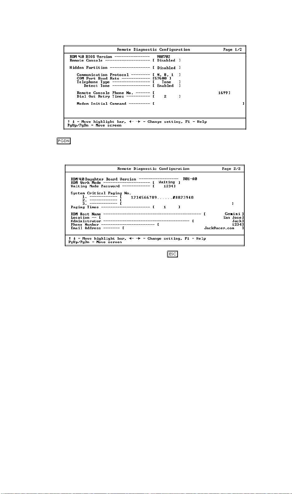
Press to view page two of the Remote Diagnostic Configuration menu. This
page is for configuring the RDM module functions.
After entering all the required settings, press to exit the RDM BIOS setup.
Chapter 3 – Configuring the RDM Server
3-3

3.2.2 RDM 4.0 BIOS Version
This parameter specifies the version of the RDM BIOS.
3.2.3 Remote Console
This parameter lets you enable or disable a connection to the RDM manager
station. If enabled and conditions are met, the RDM enabled server dials the
RDM manager station using the phone number specified in the Remote Console
Phone No. parameter (see section 3.2.8) when the server reboots.
Once a connection is established, both the RDM server and RDM manager station
display the same screen which enables the RDM manager station to function the
same as the server console. Setting this to Disabled deactivates the RDM
manager station.
3.2.4 Hidden Partition
If you want the hidden partition to become accessible, set this parameter to
Enabled. When enabled, the server boots to the hidden partition.
To disable the hidden partition and return to the normal booting procedure, set
this parameter to Disabled.
We recommend that you set this parameter
to Enabled especially when you are
troubleshooting system problems.
RDM User’s Guide
3-4

3.2.5 Communication Protocol
This parameter specifies the parity, stop bits, and data length for the COM port to
be used for the RDM connection. This is fixed at N (none), 8, 1 setting and is nonconfigurable.
3.2.6 COM Port Baud Rate
This parameter lets you set the transfer rate of the COM for the RDM connection.
The parameter setting depends on your modem specification; therefore, before
you change the setting of this parameter, check your modem user guide.
Check your System Security Configuration
settings in the BIOS Setup and make sure
that you have assigned a port to serial 2.
Otherwise, RDM will not function.
3.2.7 Telephone Type
Telephone types vary for every country or area. Though the Tone type is the
most common, there are still other areas that use the Pulse type. Check your
telephone type before resetting this parameter.
Detect Tone
This parameter becomes configurable only if the Telephone Type parameter is set
to Tone. When enabled, RDM checks for the existence of the telephone tone first
before it dials out. When disabled, RDM proceeds with the dialing process
without checking for the telephone tone.
We recommend that you leave this
parameter to its default setting (Enabled).
Chapter 3 – Configuring the RDM Server
3-5

3.2.8 Remote Console Phone Number
This parameter allows you to set the phone number of the RDM manager station
that the RDM module must dial once RDM is activated and the Remote Console
is enabled. To set it, highlight the parameter and enter the Remote Console phone
number.
Remote Console Phone No.... ...........[ 5455299 ]
Remote Console Number
If the remote console phone number is using a Private Branch eXchange1 (PBX)
line, then you must enter six commas (,) after the phone number and before the
extension number, if any. When entering the extension number, we recommend
that you insert a comma after each number. The commas specify delay.
Extension Number
Remote Console Phone No... ............[5455299,,,,,,6,6,4,9]
Delay
If this parameter is left blank, the Remote Console calling function is disregarded.
3.2.9 Dial Out Retry Times
This parameter allows you to specify the maximum number of times the RDM
server must retry to connect to the RDM manager station once the server fails and
RDM is activated. If the server has completed the specified number of tries and
the connection still fails, the server bypasses RDM and goes into normal mode.
1
PBX is a telephone switching system that requires manual operation to get an outside line. This is
synonymous to PABX - Private Automatic Branch eXchanges.
RDM User’s Guide
3-6

3.2.10 Modem Initialization Commands
Some modems require specific commands for initialization. This parameter
allows you to specify the required command to enable your system to support
special types of modems. If you do not specify a command, BIOS uses the default
method to initialize the modem.
Specify an initialization command only when
you receive a Modem Initial Command Fail
error message. Otherwise, leave this
parameter blank.
3.2.11 RDM Daughter Board Version
This parameter displays the version number of your RDM daughter board.
Chapter 3 – Configuring the RDM Server
3-7
3.2.12 RDM Work Mode
Before you set this parameter, make sure
that you have an RDM module. Otherwise,
you cannot set this parameter.
This parameter lets you specify the RDM work mode or the notification
procedure. The mode options are listed in the following table:
Table 3-1 RDM Work Modes
Mode Description
Waiting
(Runtime
Remote mode)
Reboot Once RDM is activated, the server dials the pager
Disabled Deactivates RDM.
Once RDM is activated, the server dials the pager
number(s) specified in the System Critical Paging
No. parameters (see section 3.2
the RDM manager station to call in. When the
RDM manager station calls in with the specified
phone number and password, the Agent
Information appears on the RDM manager station
screen.
number(s) specified in the System Critical Paging
No. parameters (see section 3.2
the system to its original operating system.
.14) and waits for
.14) and reboots
Once the server hangs, the RDM LED lights
automatically.
3.2.13 Waiting Mode Password
This parameter prevents unauthorized access to the server. To set a password,
highlight the parameter and enter your code. Your password may contain at least
RDM User’s Guide
3-8

three, but no more than eight, alphanumeric characters (i.e., the 26 letters of the
alphabet plus the numbers 0-9). You cannot use special characters.
Make sure to remember your password. Before the server grants RDM manager
station access, you will be prompted to enter this password.
You must set a password; otherwise, the
server will not establish connection with the
RDM manager station.
3.2.14 System Critical Paging Numbers
These parameters allow you to set the pager numbers that the RDM module must
dial once the server fails or hangs.
Entering the Pager Number
To enter the pager number, do the following:
Highlight 1, 2 or 3.
1.
Type in the pager number followed by commas ‘,’ which specify the delay.
2.
The number of commas to enter varies for every country depending on the
communication switch used.
Make sure that you enter the appropriate number of commas; otherwise, the
pager may not receive the complete message.
Determining the Number of Commas
You can use any modem utility to determine the number of commas to enter. For
example, to determine the number of commas via Windows Terminal:
Initialize the COM port assigned for the modem function.
1.
Enter the system administrator’s pager number (for example: 54555499, , , ,
2.
XXXX#). The default is four commas (, , , ,). If paging is successful, that
means that the number of commas entered is enough. If not, add one comma
to your entry. Repeat the procedure until paging is successful.
You may also include the server modem number or the message that you want to
send in the pager notification. To do this, enter a # sign after the commas. Then,
Chapter 3 – Configuring the RDM Server
3-9

enter your message. At the end of the message, type another # sign. The message
entry must start and end with # sign.
To bypass this feature, do not enter any number after the comma.
(,) Delay
System Critical Paging No.
1. [ 123456789,,,,,,8823940#]
2. [ 847982493,,,,,,3442442#]
3. [ ]
Pager Number Message (valid entries: 0-9,
)
*
Leave this parameter blank to disregard this function.
You can enter a maximum of three sets of
pager numbers. Each line accommodates a
maximum of 45 characters.
Follow the same procedure to set the
additional pager numbers.
3.2.15 Paging Times
Similar to the Dial Out Retry Times parameter, this parameter lets you specify the
number of times the server must dial the pager number(s) specified in the System
Critical Paging No. parameters (see section 3.2.14) once the server fails and RDM
is activated.
3.2.16 RDM Host Name
This parameter allows you to specify your server host name.
3.2.17 RDM Location
This parameter allows you to specify your server location.
RDM User’s Guide
3-10

3.2.18 Administrator
This parameter allows you to specify your administrator’s name.
3.2.19 Phone Number
This parameter lets you specify your administrator’s phone number.
3.2.20 Email Address
This parameter lets you specify your administrator’s email address.
3.3 Setting RDM Operation Modes
The RDM server can be set to run in one of three different RDM operation modes:
local mode, remote mode, and runtime mode. These sections will describe how
to configure the RDM server and RDM manager station to run in different RDM
operation modes.
3.3.1 RDM Local Mode
In RDM Local mode, the RDM server boots to the hidden RDM partition, which
allows you to run diagnostics and other test programs on the server locally.
Enabling Local Mode
To enable the Local mode, do the following:
1.
Reboot the server and enter the BIOS Setup.
From the main menu, select Remote Diagnostic Configuration.
2.
Set the Hidden Partition parameter to Enabled.
3.
Save your changes and exit the BIOS Setup. The server reboots automatically.
4.
Chapter 3 – Configuring the RDM Server
3-11

Exiting from Local Mode
After running the diagnostics, you can return the system to normal operation by
exiting from RDM Local mode.
To exit from RDM Local mode, do the following:
Reboot the server and enter the BIOS Setup.
1.
From the main menu, select the Remote Diagnostic Configuration option.
2.
Set the Hidden Partition parameter to Disabled.
3.
Save your changes and exit the BIOS Setup.
4.
3.3.2 RDM Remote Mode
In RDM remote mode, the system boots to the hidden RDM partition and
establishes a remote connection, which makes all the RDM features available to
both the RDM server and RDM manager station sites. However, the RDM
Remote mode can only be activated by a local operator in the server BIOS Setup.
Enabling Remote Mode
To enable the RDM Remote mode, do the following:
Reboot the server and enter the BIOS Setup.
1.
From the main menu, select the Remote Diagnostic Configuration option.
2.
Set the Remote Console parameter to Enabled.
3.
Set the Dial Out Retry Times parameter to the number of times the server
4.
must attempt to call the RDM manager station to make a connection.
In the Remote Console Phone No. parameter, enter the RDM manager station
5.
phone number.
Save your changes and exit the BIOS Setup. The server reboots and dials the
6.
specified RDM manager station phone number to establish remote
connection.
RDM User’s Guide
3-12

Remotely Accessing the RDM Server
Once the RDM server is rebooted into the RDM Remote mode, the RDM server
will try to establish a connection with the RDM manager station, with the
following screen on the server console:
BIOS v2.1
0032384 KB Memory Good
RDM Module Detected
Remote Console Dialing Out. Please Wait…
Connect Successfully
Check Point: 88
Enter Setup, Remote Site press ! key, Local Site press CTRL_ALT_ESC
ACR45E00-Io8-9709701-R01-B0-T3.RC311
If the remote RDM connection is successfully established, you can access all RDM
utilities from the RDM manager station.
From the RDM manager station, you can do one of the following:
• Press to view the server BIOS Setup. For details on BIOS Setup, refer
to the system’s documentation.
• Boot to the hidden partition.
RDM manager station supports VGA text mode
only.
Chapter 3 – Configuring the RDM Server
3-13

Exiting from Remote Mode
If you want to resume the server system to normal operation mode, the server
needs to exit from the RDM Remote mode.
To exit from RDM Remote mode, do the following:
1.
Run the RDM manager station program (See Chapter 4).
From the menu bar, select Agent.
2.
Select the Reboot Agent command. The Confirm RDM Server Reboot dialog
3.
box appears.
Click on Disconnect. The server system reboots, terminates connection, and
4.
returns back to normal operating mode.
If you click on the Keep Monitoring option,
the server reboots without disabling the
connection with the remote RDM manager
station.
3.3.3 RDM Runtime Mode
The RDM Runtime mode is the normal RDM operation mode in which the server
system operates under its installed operating system. In the event of server
system failure, the RDM driver stops sending heartbeat signals to the RDM
module which, then, takes over the control of the server system and the COM
port, and dials the pager number(s) to notify the specified system administrator.
RDM User’s Guide
3-14

Activating RDM
When the server system fails or hangs, the RDM driver stops sending heartbeat
signal to the RDM module. When the RDM module does not receive any
heartbeat signal for a certain period of time, the RDM LED lights up indicating
that RDM has been activated. However, if the temperature of any processors in
the system exceed their limit, the RDM module will immediately turn off the
system for safety purpose.
When RDM is enabled, the RDM module takes control of the COM port
connected to the modem and functions as the modem controller. It notifies the
system administrator (through paging) of the server failure. RDM operates
according to the RDM Work Mode specified in BIOS Setup and allows the system
administrator to access the server remotely from the RDM manager station.
There are two types of Runtime mode operations:
• Runtime Reboot Mode (Reboot Mode), and
• Runtime Remote Mode (Waiting Mode)
The sections below discuss how each mode operates.
Make sure that the modems are turned ON
during remote RDM operation.
Runtime Reboot Mode (Smart Reboot)
In this mode, RDM checks the status of all processors installed in the server. If
there is at least one processor in good condition, the server reboots automatically.
If the temperatures of all processors in the system are higher than the maximum
limit, the RDM module will not reboot the system until the temperature of at least
one of the processors returns to normal.
To minimize system down time, we recommend
that you set the RDM Work Mode parameter in
the BIOS Setup to Reboot. This setting
enables the server to start paging and reboot
immediately in the event of system failure.
Take note that it is normal to hear a beep
Chapter 3 – Configuring the RDM Server
3-15

sound during reboot.
Enabling Runtime Reboot Mode
Follow these steps to enable the Runtime Reboot mode:
1.
Enter the BIOS Setup.
Highlight the Remote Diagnostic Configuration option.
2.
Go to page 2 of the RDM Configuration menu.
3.
Set the RDM Work Mode parameter to Reboot.
4.
After Smart reboot, the processors with very
high temperatures will be disabled. To
enable the processors, you need to turn off
the system.
5. Specify the system administrator’s pager number in the System Critical
Paging Number parameter. You may enter a maximum of three pager
numbers.
Specify the setting for the Paging Times parameter.
6.
Save your changes and exit the BIOS Setup. The server reboots and runs in
7.
Runtime Reboot mode.
RDM User’s Guide
3-16

Runtime Remote Mode
In this mode, the RDM module starts paging, when the server hangs or fails.
Once the page is received, the administrator can establish a connection from the
RDM manager station to the RDM Server. Once the connection is established, the
RDM Agent Information window appears on the screen, as shown in Figure 3-1.
Figure 3-1 Agent Information Window
Through the RDM manager station, the system administrator can access the
following from the remote RDM-enabled server:
• Agent Information
• DMI
• Event Log
Chapter 3 – Configuring the RDM Server
3-17

• Failure Snapshot
• RDM Information
• Current Status
• Exit
For detailed descriptions of these items, see the next chapter, Using the RDM
Manager Station.
Enabling Runtime Remote Mode
To enable the Runtime Remote mode, do the following:
1.
Enter the BIOS Setup.
Highlight the Remote Diagnostic Configuration option.
2.
Go to page 2 of the RDM Configuration menu.
3.
Set the RDM Work Mode parameter to Waiting.
4.
Enter a password in the Waiting Mode Password parameter. You will use
5.
this password to access the RDM server from an RDM manager station.
Specify the system administrator’s pager number in the System Critical
6.
Paging Number parameter. You may enter a maximum of three pager
numbers.
Specify the setting for the Paging Times parameter.
7.
Save your changes and exit the BIOS Setup. The server reboots automatically,
8.
and runs in Runtime Remote mode on the event of server system failure.
RDM User’s Guide
3-18

Chapter 4 Using the RDM Manager
Station
This chapter describes how to use the RDM manager station.
4.1 Running the RDM Manager Station
To optimize the screen resolution, select
800x600.
4.1.1 Starting the RDM Manager Station
To start the RDM manager station, connect to the RDM server by doing the
following:
From Windows, click on the RDM icon.
1.
The RDM manager station starts initializing the COMx port which has been
connected to the modem. The message Initialize COM1 successfully
displays if the initialization is successful.
Click on OK to continue.
2.
This process is followed by the initialization of the modem. The message
Initialize modem successfully appears if the modem initialization is
successful.
Click on OK.
3.
The screen displays the RDM station window.
Chapter 4 – Using the RDM Manager Station
4-1

4.1.2 Connecting to the RDM Server
To access the remote server from the RDM manager station, do the following:
From a remote location, launch the RDM station program. The RDM Station
1.
Utility window appears on the screen.
Figure 4-1 RDM Station Utility Window
For more details on the RDM Station Utility, see section 4.3.
Do one of the following:
2.
• Click on the Connection button ( ) from the Toolbar, or
• Click on the Phone menu and select the Agent Phone Book command
If the RDM agent icon already exists, double-click it. The station dials to the
3.
RDM agent automatically. Otherwise, create a new RDM agent. See section
4.4.7 for details on creating a new RDM agent.
When the call is successful, the RDM module verifies the entered password.
If the password matches the RDM agent password for remote connection, the
station displays the Agent Information window on the screen automatically.
See Figure 4-2.
RDM User’s Guide
4-2

4.2 RDM Agent Information
Once the RDM connection is established, the RDM Agent Information window is
displayed on the RDM manager station screen, as shown in Figure 4-2. Click on
the RDM Agent Information buttons for RDM agent information. Click on the
function buttons to perform RDM functions.
Figure 4-2 Agent Information Window
Chapter 4 – Using the RDM Manager Station
4-3
4.2.1 RDM Agent Information Buttons
From the RDM Agent Information window, you can do the following by clicking
the respective RDM Agent Information button:
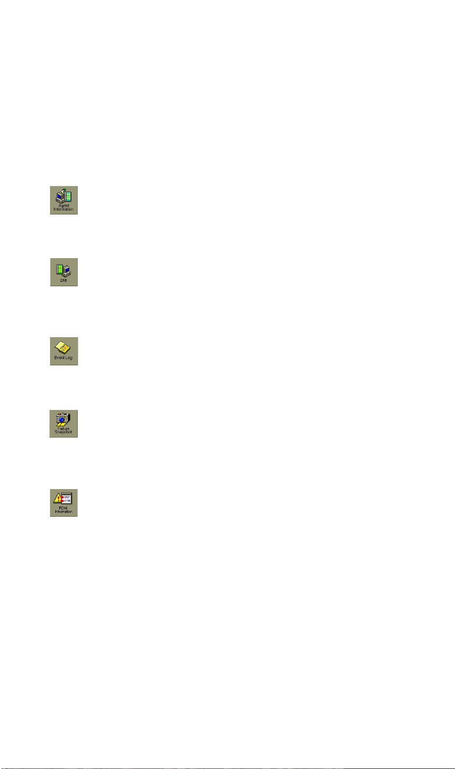
Agent Information
Displays important agent information (see Figure 4-
2).
DMI
Desktop Management Information displays detailed
information regarding the system board and system
components (see Figure 4-3).
Event Log
Displays the system event log (see Figure 4-4).
Failure Snapshot
Displays the System Failure Snapshot window (see
Figure 4-5). This window contains important
information about the server.
RDM Information
Displays the RDM settings in CMOS setup, such as
pager number, RDM working mode, password, etc.
RDM User’s Guide
4-4

Figure 4-3 DMI Information Window
Figure 4-4 Event Log Window
Chapter 4 – Using the RDM Manager Station
4-5

Figure 4-5 Failure Snapshot Window
Figure 4-6 Current Status Window
RDM User’s Guide
4-6
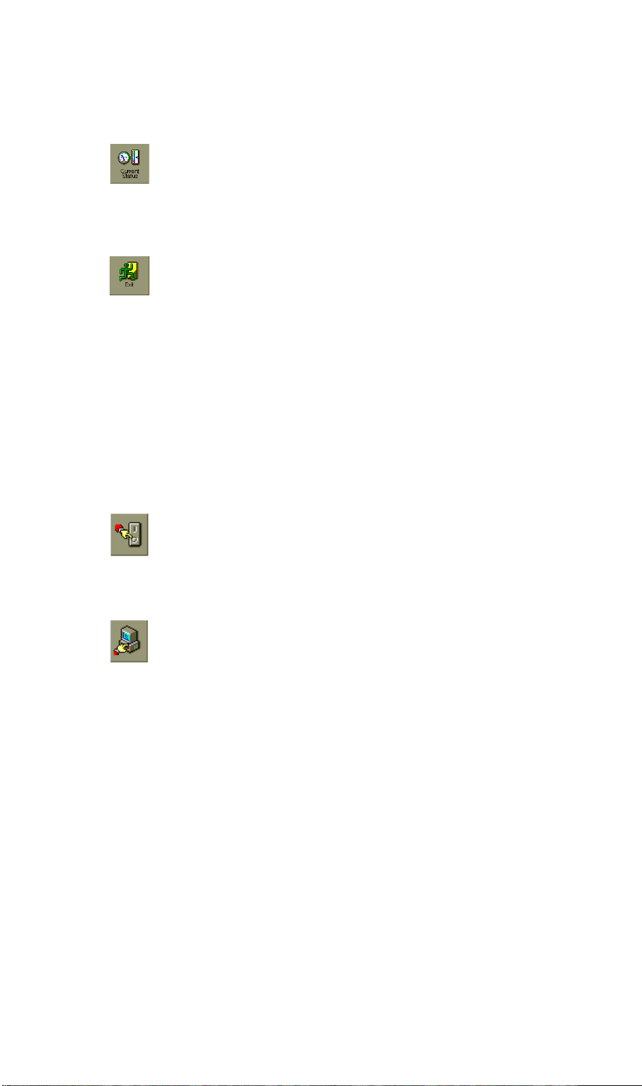
Current Status
Displays the current hardware component (CPU,
system voltage, system temperature, fan, fuse, etc.)
status of the server (see Figure 4-6).
Exit
If you click this button, a message box appears to ask:
Do you want to keep waiting? If you select Yes, the
RDM manager station cuts off the existing connection
with the server, and allows the server to remain
available for other RDM connections.
4.2.2 RDM Agent Information Functions
From the RDM Agent Information window, you can invoke the following RDM
Agent Information functions:
Power On/Off
Reboot
Turns off the server. If you click this button, the
message System turned off appears. Click on OK.
Displays the Reboot Options dialog box and reboots
the server according to the specified reboot options
(see Figure 4-7).
Chapter 4 – Using the RDM Manager Station
4-7
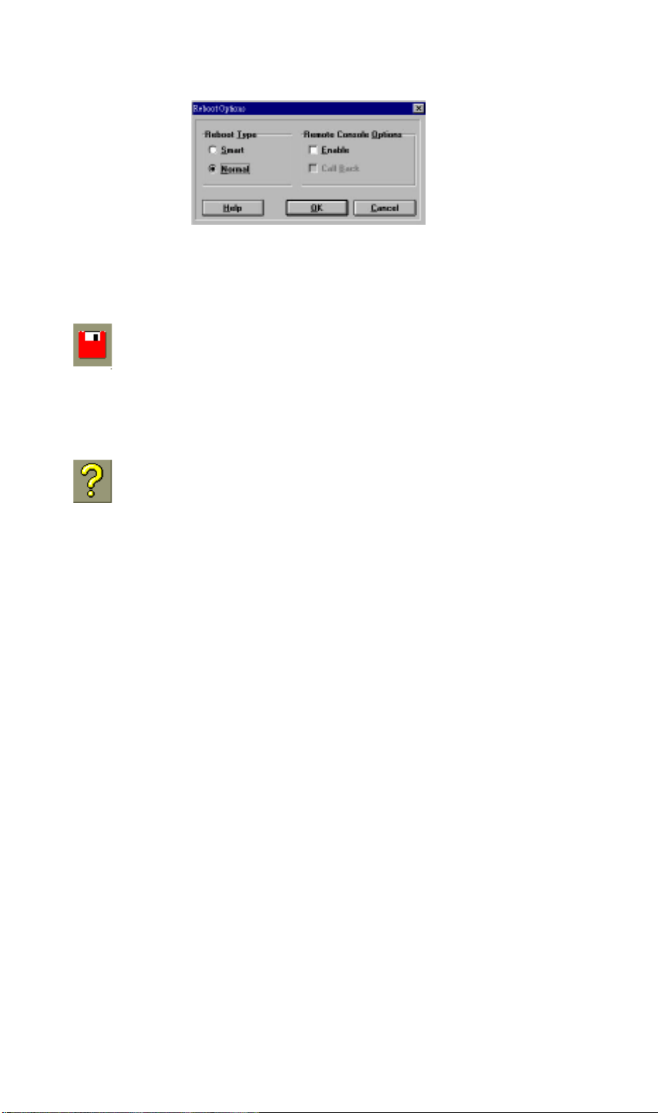
Figure 4-7 Reboot Options Dialog Box
Save
Saves a Snapshot as a file with .TXT extension.
Help
Displays the Help information.
4.2.3 RDM Reboot Options
From the RDM reboot options dialog box, the following reboot options are
available:
RDM User’s Guide
4-8
Smart Reboot
When the Smart Reboot option is selected, RDM checks the status of all
processors installed in the server. If there is at least one processor that is in good
condition, the system reboots to that processor automatically. After reboot, the
following message box appears:
Figure 4-8 Smart Reboot Message Box
If all processors are in bad condition, a message informing you of the condition of
the processor(s) appears, asking if you still want to force to reboot the system.
Click Yes to “force” the reboot of the server. The system will use all the
processors installed in it to reboot.
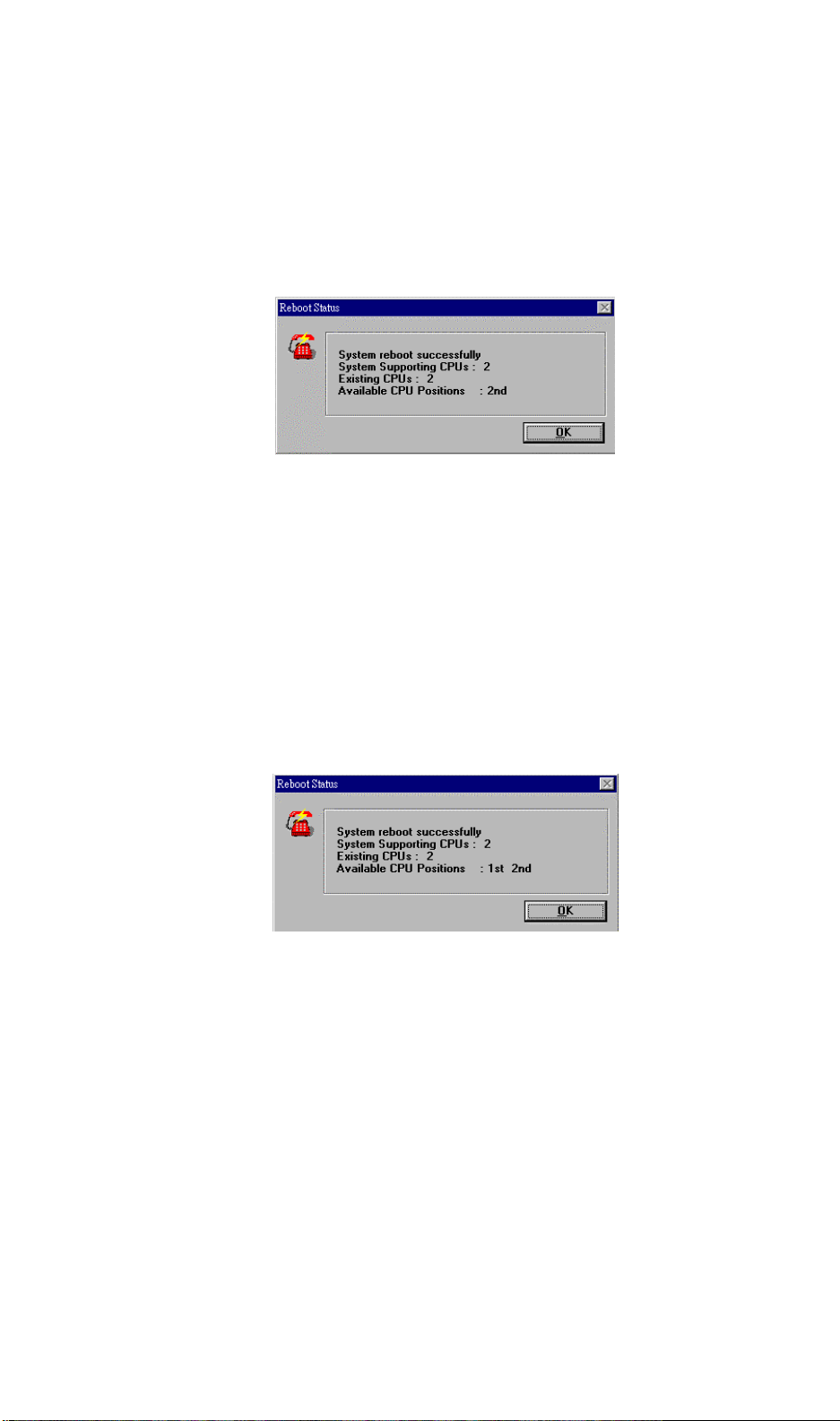
Normal Reboot
When selected, RDM checks the status of all the processors installed in the
server. If all processors are in good condition, the system reboots and shows the
following message:
Figure 4-9 Successful Normal Reboot Message Box
Chapter 4 – Using the RDM Manager Station
4-9

If any of the processors are in bad condition, a message informing you of the
condition of the processor(s) appears.
Figure 4-10 Normal Reboot Fail Message Box
Click on OK, and then another message box appears to confirm if you want to
force a reboot.
use all the processors installed to reboot.
Click on Yes to “force” the reboot of the server. The system will
4.2.4 RDM Manager Station Options
From the RDM reboot options dialog box, the following RDM manager station
options are available:
Enable
Maintains remote connection after server reboots and allows the RDM manager
station to fully control the server.
CallBack
When selected, remote connection cuts off before the server reboots. After
reboot, the server dials back to the RDM manager station to resume connection.
This option is recommended if you want to pass the connection charges to the
server.
After verifying your settings, click on OK. The server reboots according to your
specified settings.
RDM User’s Guide
4-10

4.3 RDM Manager Station Utility
This section describes the functions available through the RDM manager station
utility.
4.3.1 RDM Manager Station Utility Menus
File Menu
The File menu contains the following commands:
View Snapshot File…
Exit
Displays a saved Snapshot file.
Closes the RDM station utility.
Edit Menu
The Edit menu contains the following commands:
Clear Window
Save Log File
Stop Saving Log
Clears the utility screen.
Saves the current screen as .LOG file.
This is very useful especially if you are
debugging or troubleshooting. By
default, this option is grayed out, i.e.,
disabled.
Disables the Saving Log File function.
By default, this option is grayed out,
i.e., disabled.
Chapter 4 – Using the RDM Manager Station
4-11

View Menu
The View menu contains the following options:
Toolbar
Status bar
Shows or hides the utility Toolbar.
Shows or hides the status bar, i.e., the
bar located at the bottom of the utility
window.
Settings Menu
The Settings menu contains the following options:
Communication
Lets you configure the default settings
for the communication port for the
RDM manager station.
Font
Allows you to change your font
properties.
Phone Menu
The Phone menu contains the following commands:
Hang Up
Disables the telephone connection. By
default, this option is grayed out, i.e.,
disabled. Once remote connection is
established, this option becomes
enabled.
Agent Phone Book
RDM User’s Guide
4-12
Allows you to add a new agent. To
dial to the agent, double-click on its
icon.

Transfer Menu
The Transfer menu enables the RDM manager station and the RDM server to
send and receive files.
Send File
Enables the RDM manager station to
send files to the server.
Receive File
Enables the RDM manager station to
receive files from the server.
By default, these options are grayed out, i.e.,
disabled. Once remote connection is
established and server boots to hidden partition,
the options become available.
Agent Menu
The Agent menu contains the following commands:
Install TSR
Uninstall TSR
Refresh Screen
Allows you to install Terminate and
Stay Resident (TSR) program. This
program is stored in RAM so that it
can be activated easily. This option is
available only in RDM v1.X.
Removes or uninstalls the TSR
program from the memory. This
option is available only in RDM v1.X.
Updates the current screen.
RDM Talk
Reboot Agent
About Agent
Runs the Talk utility. This utility
allows users located at
RDM manager
station and RDM agent to
communicate online.
Allows you to reboot the server from
the RDM manager station.
Displays the copyright and version
Chapter 4 – Using the RDM Manager Station
4-13

number of the server’s RDM driver.
By default, all options are grayed out, i.e.,
disabled. Once a remote connection is
established and the server boots to the
hidden partition, these options become
available.
Help Menu
The Help menu contains the following commands:
Index
Displays the Help index. The index
helps you to find the information that
you want easily.
Using Help
About RDM
Manager Station
Opens the RDM online help.
Displays the copyright, version number
and release date of the RDM station
utility.
4.3.2 RDM Manager Station Toolbar Buttons
CLS
Connection
Clears the screen.
Dials the server phone
number automatically when
the system fails. The button
becomes gray or disabled
after remote connection is
established.
RDM User’s Guide
4-14

Talk
Refresh Screen
Opens the Talk utility. This
utility allows the users
located at the RDM manager
station and RDM agent to
communicate online.
Updates the current screen.
Start Log
Stop Log
Send File
Receive File
Reboot
Help
Saves the current screen as a
.LOG file. This is very useful
if you are debugging or
troubleshooting. By default,
this button is grayed out, i.e.,
disabled. Once remote
connection is established, it
becomes available.
Stops the logging function.
By default, this button is
disabled. Once the Start Log
function is enabled, this
button becomes available.
Enables the RDM manager
station to send files to the
server.
Enables the RDM manager
station to receive files from
the server.
Allows you to reboot the
server from the RDM
manager station.
Opens the RDM online help.
Chapter 4 – Using the RDM Manager Station
4-15

4.4 RDM Manager Station Functions
This subsection describes the various RDM manager station functions you can
perform through the RDM manager station utility.
4.4.1 Viewing a Snapshot File
To view a previously saved Snapshot file, do the following steps:
1.
From the menu bar, select the File menu.
2.
Select the View Snapshot File command. The Open System Information File
dialog box appears.
Figure 4-11 Open System Information File Dialog Box
3. From the Folders box, select the path where the Snapshot file is located.
RDM User’s Guide
4-16

4. From the File Name list box, select the Snapshot file.
5.
After making your selection, click on Open. The screen displays the selected
Snapshot file.
Figure 4-12 Snapshot File Sample
Chapter 4 – Using the RDM Manager Station
4-17

4.4.2 Clearing the Screen
To clear the screen, you can do one of the following:
• Click on the Clear button ( ) from the Toolbar.
• From the menu bar, click on the Edit menu and select the Clear Window
command.
4.4.3 Saving a Log File
If you want to save the current screen as a .LOG file, do the following:
1.
Do one of the following:
• Click on the Log button ( ) from the Toolbar.
• Click on the Edit menu and select the Save Log File command.
The Save Log File dialog box appears.
RDM User’s Guide
4-18

Figure 4-13 Save Log File Dialog Box
2. Enter a filename in the File Name box, and specify the path where you want
to save the .LOG file in the Save in box.
Click on Save to save the configuration to the specified filename, or click on
3.
Cancel to disregard the entries and quit the Save Log File dialog box.
The Save Log File function of RDM v1.X
differs from RDM v3.0X. In RDM v1.X, all
screens that appear from the time you clicked
the Save Log File button (
) will be saved to
the specified filename, until you click on the
Disable Save Log File button ( ).
In RDM v3.0X, only the current screen on
display when you clicked the
Save Log File
button ( ) will be saved. To save the
following screens, you must click the Save
Log File button after each screen. All saved
screens will be appended to the specified Log
filename.
Chapter 4 – Using the RDM Manager Station
4-19

4.4.4 Disabling the Saving Log File Function
To disable the Saving Log File function, do one of the following steps:
• Click on the Stop Log button ( ) from the Toolbar.
• From the menu bar, click on the Edit menu and select the Stop Saving
Log command.
4.4.5 Configuring RDM Manager Station Settings
To configure RDM, follow these steps:
1.
Select Settings from the menu bar.
2.
Select the Communication command. The Communication Settings dialog
box appears.
Figure 4-14 Communication Settings Dialog Box
RDM User’s Guide
4-20

3. If the modem currently in use requires a special command for initialization,
specify the command in the Initialize Command box. We recommend that
you use the default modem initialization command. To do this, click on the
Load Default button.
If the modem initialization fails, check your
modem’s manual for the proper initialization
command and enter it in the Initialize
Command box.
4. Click on the down arrow of the COM Port box and select the COM port that
you want to assign for the modem function.
Click on the down arrow of the Baud Rate box and select the baud rate that
5.
you want to support. The default setting is 57600.
We suggest that you use the default settings
for all of the other parameters.
4.4.6 Setting the Font Properties
You can select the font that you want to appear on the RDM manager station
window for displaying text.
To select a font, do the following:
1.
In the menu bar, select the Settings menu.
2.
Select the Font command. The Font dialog box appears.
Chapter 4 – Using the RDM Manager Station
4-21

Figure 4-15 Font Dialog Box
3. In the Font box, select the font type.
4.
In the Font Style box, select the font style.
5.
In the Size box, select the font size.
6.
After you have made your selections, the character type appears in the
Sample box. Verify your settings, and click on OK.
4.4.7 Creating a New RDM Agent
To create a new RDM agent, do the following:
1.
From the menu bar, click on the Phone menu and select the Agent Phone
Book option. The Agent Phone Book window appears.
RDM User’s Guide
4-22

Figure 4-16 Agent Phone Book Window
2. Click on the Add Agent Here icon. The Agent Connection Wizard appears
on the screen.
Chapter 4 – Using the RDM Manager Station
4-23

Figure 4-17 Agent Connection Wizard (Screen 1)
3. Enter the RDM agent in the Agent Name textbox, RDM agent phone number
in the Phone No. to Dial textbox, RDM manager station’s phone number in
the Phone No. to Dial Back textbox, and the correct password in the RDM
Password textbox.
The RDM password entries must match with
that specified in BIOS.
4. Then click on Next to proceed. The following screen appears:
RDM User’s Guide
4-24

Figure 4-18 Agent Connection Wizard (Screen 2)
5. In this screen, you can set your speaker volume, enable the Auto-answer and
Detect Dial Tone features, and specify the modem initialization command,
COM port occupied by the modem, and the baud rate. If you do not know
how to set the modem initialization command, click on the Load Default
button. This sets the default modem initialization command automatically.
After you have entered the necessary settings, click on Next.
6.
7.
The next screen asks if you wish to connect to the agent immediately. If you
do, click on the Automatically Dial to Agent Now checkbox, then click on
Finish. The RDM manager station dials the server number automatically.
When the call is successful, the RDM module verifies the entered password
and the following message box appears:
Chapter 4 – Using the RDM Manager Station
4-25

Figure 4-19 Dialing Message Box
8. If the password matches the server’s password for remote connection, the
Agent Information window appears (see Figure 4-2). This window displays
general information about the server.
After verifying your settings, click on Exit. The server boots according to
9.
your specified settings.
4.4.8 Sending Files
Before you send files, make sure that the agent is
in DOS command mode and that the files to be
transferred are stored on the local hard disk.
To send files to the server, follow these steps:
1.
D o either of the following:
• From the menu bar, click on the Transfer menu and select the Send File
command.
• Click on the Send button ( ) from the Toolbar.
The Open File dialog box appears.
RDM User’s Guide
4-26

2. Choose the file(s) that you want to send and then click on OK . You may
choose as many files as you want. Then the Remote Directory Path dialog
box appears.
Figure 4-20 Remote Directory Path Dialog Box
3. Enter the directory in the server where you want to copy the selected files in
the Full path name of remote directory entry box.
After verifying the entered path, click on OK. The File Transfer Status dialog
4.
box appears.
Figure 4-21 File Transfer Status Dialog Box
5. To stop the sending operation of the file that the RDM manager station is
currently transferring, click on the Terminate button. To stop the sending of
all the selected files, click on the Terminate All button.
Chapter 4 – Using the RDM Manager Station
4-27

If the file(s) already exist, a message box prompting you to confirm the
replacement of the files will appear.
Click on Yes to confirm the replacement of the file that is currently being
transferred.
Click on Yes to All to confirm the replacement of all the common files.
Click on No if you do not want to replace the file.
Notice that the OK button remains grayed until the file transfer is completed.
The Cancel button becomes grayed if the file transfer fails.
To close the Transfer Status dialog box, click on OK. To disregard the operation
that has been performed previously, click on Cancel.
The maximum file size that can be
transferred is 18 MB.
4.4.9 Receiving Files
Before you receive files, make sure that the
agent is in DOS command mode.
To receive files from the server, follow these steps:
Do one of the following:
1.
• From the menu bar, click on the Transfer menu and select the Receive
File command.
• Click on the Receive button ( ) from the Toolbar.
The Receive File Name dialog box appears.
RDM User’s Guide
4-28

Figure 4-22 Receive File Name Dialog Box
2. Enter the path where the files are located in the Full path name of remote file
entry box and then click on OK. The File Receive Status dialog box appears.
Notice that the OK button remains grayed until the transfer of file(s) is
3.
completed. To stop the transfer of file(s) or to disregard the operation that
has been performed previously, click on Cancel.
If the file(s) already exist, a message box prompting you to confirm the
replacement of the files will appear.
Click on Yes to confirm the replacement of the file that is currently being
transferred.
Click on Yes to All to confirm the replacement of all the common files.
Click on No if you do not want to replace the file.
When the file transfer is finished, click on the OK button to close the Receive
4.
Status dialog box.
The maximum file size that can be
transferred is 18 MB.
Chapter 4 – Using the RDM Manager Station
4-29

4.4.10 Refreshing the Screen
To “refresh” the screen, you can click on the Agent menu from the menu bar and
select the Refresh Screen command, or click on the Refresh Screen button (
from the Toolbar. This updates the RDM manager station screen.
4.4.11 Running the Talk Utility
The Talk utility allows the user at the RDM manager station to directly
communicate with the user at the server site via PC. Users at both sites can send
messages by typing in the text.
To run the Talk utility, follow these steps:
Do one of the following:
1.
• From the menu bar, click on the Agent menu and select the RDM Talk
command.
• Click on the Talk button ( ) from the Toolbar.
The Talk Utility screen appears both on the server site and on the local site
monitors.
)
Type in the messages that you want to send. The messages from the server
2.
site appear in the upper portion of the screen, while the messages from the
RDM manager station appears in the lower portion
To exit this utility, the user at the RDM manager station must press .
3.
RDM User’s Guide
4-30

4.4.12 Rebooting the Server
To reboot the server, do the following:
1.
Do one of the following:
• From the menu bar, click on the Agent menu and select the Reboot Agent
command.
• Click on the Reboot button ( ) from the Toolbar.
The Confirm RDM Server Reboot dialog box appears.
Figure 4-23 Confirm RDM Server Reboot Dialog Box
2. Click on the Disconnect button to disable RDM and reboot the server to
normal mode.
Click on the Keep Monitoring button to reboot the server. If you suddenly
decide not to reboot the server, click on Cancel.
After making your choice, the dialog box disappears from the screen and the
3.
selected reboot option is performed.
Chapter 4 – Using the RDM Manager Station
4-31

Chapter 5 Troubleshooting
This chapter lists the common problems that you may encounter during RDM
operation, followed by the possible corrective action(s).
5.1 RDM Agent Troubleshooting
The RDM LED indicator is not lit while running RDM in either Local or
Remote mode.
The LED indicator lights up in Runtime Remote mode only. After the server
reboots itself, the LED indicator will turn off. The Runtime Remote mode is
active only during a server failure.
The RDM Work Mode parameter is grayed out.
Check the RDM module and make sure that it is properly plugged into its socket.
The message “No RDM Hidden Partition” appears.
Do the following:
1.
Enter the BIOS Setup.
Set the Hidden Partition to Enabled.
2.
Exit the BIOS Setup and save your changes.
3.
4.
Make sure that you have created the hidden partition. Refer to section 2.2.3
for instructions. If you need to recreate the RDM hidden partition, do not
forget to back up all important files before you proceed. RDM partition
creation destroys all data on the hard disk because the RDM hidden partition
must be the first partition on the primary hard disk.
Chapter 5 - Troubleshooting
5-1

5.2 RDM Station Manager Troubleshooting
When running any DOS application that requires + hotkey, RDM manager
station cannot transmit
system interception.
key to the agent site due to the Windows operating
Instead of just pressing
Shadows appear on the screen.
Do one of the following:
• Click on the Refresh button to refresh the screen.
• Click on the Hang-up button to disconnect.
+ hotkey, press + followed by the hotkey.
5.3 Modem Troubleshooting
The RDM program does not run properly.
Check the baud rate of your modem. The recommended baud rate is 57600 Kbps.
5.4 Hidden Partition Troubleshooting
If there are bad sectors or other damage in the hidden partition, do the following:
1.
Insert a bootable diskette into the diskette drive.
2.
Enter the BIOS Setup and set the Hidden Partition parameter in the RDM
BIOS to Enabled.
After the system boots from the diskette drive, use the Disk Repair tool to
3.
troubleshoot the partition.
RDM User’s Guide
5-2

5.5 BIOS Messages
The following table lists the BIOS status and error messages that you might
encounter when using RDM.
Table 5-1 BIOS Status and Error Messages
BIOS Message Description
RDM Module Detected BIOS detected an RDM module in the
system.
RDM Enabled But
Modem Not Ready
RDM Dialing Out.
Please Wait…
Connect Fail: Serial 2
Disabled
RDM Work Mode is set to Reboot or
Waiting; however there is no modem
available for the RDM module. Check if
there is a modem connected to serial
port 2. Make sure that it is ON.
RDM manager station function has
been enabled. BIOS will dial out to
connect to the RDM manager station.
This process will take a couple of
minutes.
Serial 2 is disabled. Enter the BIOS
Setup, select the System Security
option, and set an I/O port for serial 2.
Chapter 5 - Troubleshooting
5-3

Table 5-1 BIOS Status and Error Messages (continued)
BIOS Message Description
Connect Fail: Modem
Off
Connect Fail: Modem
Initial Command Fail
Modem is OFF. Check if modem is
connected to serial 2. Make sure that it is
ON.
The default modem initial command
failed. Consult your modem’s manual.
The BIOS default command is
AT&F1&C1V0X0M1L2S7=120
Connect Fail: No Dial
Tone
Connect Fail: Line
Busy
Connect Fail: No
Answer
Connect Fail: No
Telephone to Dial
Connect Fail: User
Stop Dialing Out
No RDM Hidden
Partition
Modem cannot detect a dial tone. Make
sure that the telephone is working
properly.
RDM manager station is busy now. Wait
for a few minutes, then try reconnecting.
No response from the RDM manager
station. Make sure that the RDM
manager station phone number is correct.
RDM manager station is enabled, but no
RDM manager station phone number is
set. Enter the BIOS Setup, select the
Remote Diagnostic Configuration option,
and enter the RDM manager station
number in the Remote Console parameter
screen.
The key is pressed during the RDM
dialing out process. Do not press
while RDM is dialing out unless you want
to stop the connection process.
RDM hidden partition is enabled, but no
hidden partition is created on the hard
disk. Enter BIOS Setup, select the
Remote Diagnostic Configuration option,
and disable the Hidden Partition
parameter. This returns your system to
its normal booting process. For more
details on the Hidden Partition, see
Chapter 2.
RDM User’s Guide
5-4

Appendix A RDM Module Test
Utility
This appendix describes how to run the RDM module test utility: RDMDRV.
This helps you verify that the module is working properly.
A.1 Testing Utility
RDM is equipped with one RDM module testing utility:
RDMDRV This utility simulates a server crash,
allowing you to verify that the RDM work
mode is running properly. For details, see
section A.2.
A.2 Simulating a Server Failure
You need to run a test that simulates a server failure in order to determine
whether the Runtime Remote mode is functioning properly.
To simulate a server failure, do the following:
1.
Insert a bootable diskette that contains the RDMDRV.EXE file in the diskette
drive and boot the server.
Enable the Runtime Remote mode. Refer to section 3.1.3.
2.
Appendix A - RDM Module Test Utility A-1

3. After the system boots, at the DOS prompt, type:
RDMDRV
The following message appears on the screen:
RDM daughter board test program RDMDRV v4.0, 98-05-29
Copyright 1996-1998 Acer Inc. all rights reserved.
RDM module will be active after 30 seconds.
The server is now simulating a failure. Check if the RDM LED indicator lights
up.
Once the LED lights up, RDM starts dialing the specified pager numbers. When
paging is successfully completed, you can now call the server from the RDM
manager station to establish connection. Refer to section 4.1.2 for detailed
instructions.
A.3 RDM 4.0 Utility
The RDM 4.0 Utility includes the AFLASH program that allows you to flash the
BIOS ROM.
A.3.1 AFLASH
The AFLASH program allows you to flash the BIOS ROM. When you select this
option, the screen displays a list of Flash options.
RDM User’s GuideA-2

To run the program, do the following:
1.
Select Load BIOS File to Buffer to load the BIOS binary file into the buffer.
2.
Select Program Flash ROM to flash the ROM binary file into the BIOS ROM
chip.
Press to exit.
3.
Appendix A - RDM Module Test Utility A-3

Appendix B SCO OpenServer
Installation
This appendix describes how to do a fresh installation of the SCO OpenServer
while preserving the RDM hidden partition.
B.1 SCO OpenServer 5
The default option for Hard Disk Setup is Unix only: Bad blocking 0 FF. Do
NOT accept this default option. This will overwrite the RDM partition.
Follow these steps to install SCO OpenServer 5:
1.
Boot the system with the SCO OpenServer boot diskette and the SCO
OpenServer CD-ROM loaded in their respective drives.
Follow all onscreen instructions until you reach the Hard Disk Setup entry.
2.
3.
Choose Interactive fdisk/divvy.
Appendix B - SCO OpenServer Installation B-1

4. Choose either Use the Rest of the Disk for Unix for allocating the remaining
space to Unix, or Display Partition Table to customize it.
Continue to follow all onscreen instructions to complete the installation.
5.
If you are using the SCO OSR 5 Easy Install
on the Startup CD, it will automatically detect
and preserve the existing RDM partition in
the system. If you are doing the manual
installation, you must perform steps 2
through 4 to ensure that you do not overwrite
the RDM hidden partition.
RDM User’s GuideB-2

Appendix C System Event
Types
This appendix lists all possible system events.
C.1 System Event Types
Table C-1 System Event Types
System Event Types
Single-bit ECC memory error
Multi-bit ECC memory error
POST memory resize
POST error (see Table C-2)
PCI parity error
PCI system error
System limit exceeded (see Table C-3)
System re-configuration (ESCD data changed)
Log area Reset/Cleared
Setup password fail
Power on password fail
RDM events (see Table C-4)
CPU disabled by BIOS
I/O Check Error
Appendix C – System Event Types
C-1

C.2 POST Error Events
Table C-2 POST Error Events
POST Error Events
PS/2 Keyboard Interface Error
PS/2 Keyboard Error or Not Connected
PS/2 Keyboard Locked
PS/2 Point Device Error
PS/2 Point Device Interface Error
Floppy Disk Controller Error
Floppy Drive A Error
Floppy Drive B Error
IDE 1st Channel Master Drive Error
IDE 1st Channel Slave Drive Error
IDE 2nd Channel Master Drive Error
IDE 2nd Channel Slave Drive Error
CPU BIOS Update Code Mismatch
Real Time Clock Error
CMOS Battery Bad
CMOS Checksum Error
NVRAM Checksum Error
I/O Resource Conflict(s)
Memory Resource Conflict(s)
IRQ Setting Error
Expansion ROM Allocation Failed
Onboard Serial 1 IRQ Conflict(s)
Onboard Serial 2 IRQ Conflict(s)
Onboard Parallel Port IRQ Conflict(s)
Onboard Floppy Drive IRQ Conflict(s)
Onboard Point Device IRQ Conflict(s)
RDM User’s Guide
C-2

Table C-2 POST Error Events (continued)
POST Error Events
Onboard IDE Secondary Channel IRQ Conflict(s)
Onboard ECP Parallel Port DMA Conflict(s)
Onboard Floppy Drive DMA Conflict(s)
Onboard Floppy Drive I/O Address Conflict(s)
Onboard IDE Secondary Channel I/O Address Conflict(s)
Onboard Serial Port 1 I/O Address Conflict(s)
Onboard Serial Port 2 I/O Address Conflict(s)
Onboard Parallel I/O Address Conflict(s)
Onboard Serial 1 Conflict(s)
Onboard Serial 2 Conflict(s)
Onboard Parallel Conflict(s)
Onboard IDE Primary Channel IRQ Conflict(s)
Onboard IDE Primary Channel I/O Address Conflict(s)
I2C Interface or Device(s) Error
System Management RAM Bad
CPU Clock Mismatch
Appendix C – System Event Types
C-3

C.3 System Limit Exceeded Events
Table C-3 System Limit Exceeded Events
Events
CPU temperature out of warning degree
CPU temperature out of fatal degree
CPU fan bad
CPU voltage out of range
CPU IERR# Signal issued
CPU Thermtrip# Signal issued
System voltage out of range
System temperature out of range
Chassis secure switch activated
Housing fan bad
Redundant power supply bad
Redundant power supply fan bad
Fuse bad
Hot Swap Cage Fan Bad
RDM User’s Guide
C-4

C.4 RDM Events
Table C-4 RDM Events
RDM Events
Failure time
Power off
Power on
Reboot
Remote login password fail
Remote login successfully
Remote power off
Remote reboot
CPU IERR# issued
CPU Thermtrip# issued
CPU disabled by RDM
Appendix C – System Event Types
C-5

Index
A
Disabling the saving log file
function, 4-20
Administrator, 3-11
AFLASH, A-2
B
BIOS messages, 5-3
C
Clearing the screen, 4-18
COM port baud rate, 3-5
Communication protocol, 3-5
Configuring RDM manager station
settings, 4-20
Configuring the RDM server, 3-1
RDM BIOS, 3-2
RDM operation modes, 3-1
Setting RDM operation modes, 3-
11
Connecting communication
peripherals, 2-6
Modem, 2-6
Pager, 2-6
Telephone, 2-6
Connecting to the RDM server, 4-2
Creating a new RDM agent, 4-22
D
Dial out retry times, 3-6
E
Email address, 3-11
Entering RDM BIOS, 3-2
H
Hidden partition, 3-4
Hidden partition troubleshooting, 5-
2
I
Installing RDM agent software, 2-7
Creating a hidden RDM partition,
2-7
Deleting the hidden partition, 2-8
Enabling the driver, 2-9
Installing an operating system, 2-9
Installing the RDM agent driver,
2-9
NetWare, 2-10
SCO OpenServer, 2-10
Windows NT, 2-10
Installing the RDM manager station
software, 2-11
Installing the RDM module, 2-2, 2-4
ESD precautions, 2-3
Installing, 2-4
Post-installing instruction, 2-3
Pre-installation instructions, 2-3
Index
1

M
Modem initialization commands, 3-7
Modem troubleshooting, 5-2
O
Overview, 1-1
RDM architecture, 1-2
RDM features, 1-4
P
Paging times, 3-10
Phone number, 3-11
POST error events, C-2
R
RDM 4.0 BIOS version, 3-4
RDM 4.0 utility, A-2
AFLASH, A-2
RDM agent, 1-3
RDM agent information, 4-3
Information buttons, 4-4
Information functions, 4-7
RDM manager station options, 4-
10
RDM reboot options, 4-8
RDM agent information buttons, 4-4
Agent information, 4-4
Current status, 4-7
DMI, 4-4
Event log, 4-4
Exit, 4-7
Failure snapshot, 4-4
RDM information, 4-4
RDM agent information functions, 4-
7
Help, 4-8
Power on/off, 4-7
Reboot, 4-7
Save, 4-8
RDM agent troubleshooting, 5-1
RDM architecture, 1-2
RDM agent, 1-3
RDM connectivity, 1-3
RDM manager station, 1-3
RDM BIOS, 3-2
Administrator, 3-11
COM port baud rate, 3-5
Communication protocol, 3-5
Dial out retry times, 3-6
Email address, 3-11
Entering RDM BIOS, 3-2
Hidden partition, 3-4
Modem initialization commands,
3-7
Paging times, 3-10
Phone number, 3-11
RDM 4.0 BIOS version, 3-4
RDM daughter board version, 3-7
RDM Host name, 3-10
RDM location, 3-10
RDM work mode, 3-8
Remote console, 3-4
Remote console phone number, 3-
6
System critical paging numbers, 3-
9
Telephone type, 3-5
Waiting mode password, 3-8
RDM connectivity, 1-3
RDM daughter board version, 3-7
RDM events, C-5
RDM User’s Guide
2
 Loading...