


Veriton 7900Pro/6900Pro/5900Pro
Service Guide
Service guide files and updates are available
on the AIPG/CSD web; for more information,
please refer to http://csd.acer.com.tw
PRINTED IN TAIWAN

Revision History
Please refer to the table below for the updates made on Verition 7900Pro/6900Pro/5900Pro service guide.
Date Chapter Updates
II

Copyright
Copyright © 2006 by Acer Incorporated. All rights reserved. No part of this publication may be reproduced,
transmitted, transcribed, stored in a retrieval system, or translated into any language or computer language, in
any form or by any means, electronic, mechanical, magnetic, optical, chemical, manual or otherwise, without
the prior written permission of Acer Incorporated.
III

Disclaimer
The information in this guide is subject to change without notice.
Acer Incorporated makes no representations or warranties, either expressed or implied, with respect to the
contents hereof and specifically disclaims any warranties of merchantability or fitness for any particular
purpose. Any Acer Incorporated software described in this manual is sold or licensed "as is". Should the
programs prove defective following their purchase, the buyer (and not Acer Incorporated, its distributor, or its
dealer) assumes the entire cost of all necessary servicing, repair, and any incidental or consequential
damages resulting from any defect in the software.
Acer is a registered trademark of Acer Corporation.
Intel is a registered trademark of Intel Corporation.
Other brand and product names are trademarks and/or registered trademarks of their respective holders.
IV

Conventions
The following conventions are used in this manual:
Screen messages
NOTE Gives bits and pieces of additional
WARNING Alerts you to any damage that might
CAUTION Gives precautionary measures to
IMPORTANT Reminds you to do specific actions
Denotes actual messages that appear
on screen.
information related to the current
topic.
result from doing or not doing specific
actions.
avoid possible hardware or software
problems.
relevant to the accomplishment of
procedures.
V

Preface
Before using this information and the product it supports, please read the following general information.
1. This Service Guide provides you with all technical information relating to the BASIC CONFIGURATION
decided for Acer's "global" product offering. To better fit local market requirements and enhance product
competitiveness, your regional office MAY have decided to extend the functionality of a machine (e.g.
add-on card, modem, or extra memory capability). These LOCALIZED FEATURES will NOT be covered
in this generic service guide. In such cases, please contact your regional offices or the responsible
personnel/channel to provide you with further technical details.
2. Please note WHEN ORDERING FRU PARTS, that you should check the most up-to-date information
available on your regional web or channel. If, for whatever reason, a part number change is made, it will
not be noted in the printed Service Guide. For ACER-AUTHORIZED SERVICE PROVIDERS, your Acer
office may have a DIFFERENT part number code to those given in the FRU list of this printed Service
Guide. You MUST use the list provided by your regional Acer office to order FRU parts for repair and
service of customer machines.
VI

System Specifications
Overview
Acer Verition 7900Pro/6900Pro/5900Pro are bussiness-ready desktop PCs built with latest high-performance
technology for managing demanding workload. The series of products are standalone or network-ready for
SMB. They include video and audio features for business multimedia.
Veriton 7900Pro/6900Pro/5900Pro comply with all requirements of Intel vProTM platform. The series of
products support Conroe CPU and employ Intel ICH8-DO and Nineveh LAN controller (82566DM).
Chapter 1
Chapter 1 1

Features
CPU
T Socket Type : Intel (R) Socket T LGA 775 pin
T Intel (R) CedarMill/Prester/Conroe FSB 533/800/1066 MHz
T L2 Cache varies with CPU
Chipset
T Northbridge: Intel (R) Q965
T Southbridge: Intel (R) ICH8DO
Memory
T Socket Type : DDR II so-DIMM,1.8 Voltage
T Socket Quantity : 4
T Capacity support : 256MB ~ 2GB Unbuffered ECC SDRAM module, support dual channel
T Support Memory Speed : DDR II 800/667/533 MHz
On-Board Graphic Solution
T Intel Broadwater-G on die graphic solution
T DVMT technology support
T Dual View function support (by Intel ADD2/ADD2+)
T 1 VGA port on rear side (co-lay for DVI-I required for Vista premium)
PCI Express/PCI Slot
T Slot Type: PCI Express X16
T Slot Quantity: 1
T Slot Type: PCI Express X1
T Slot Quantity: 1
T Slot Type: PCI 2.3 slot
T Slot Quantity: 2
SATA IDE
T Slot Type: SATA IDE slot
T Slot Quantity : 6
T Storage Type Support : HDD/CD-ROM/DVD-ROM/DVD-RW/DVD+RW/DVD Dual/DVD
SuperMultiPlus
2 Chapter 1

Audio
LAN
USB
T Codec : Realtek ALC888
T Compliant with Microsoft’s UAA (Universal Audio Architecture) support (rear only)
T 7.1+2 Channel Audio Support (ALC833 codec series provide 10 DAC channels that
simultaneously suppport 7.1 soud playback, plus 2 channels of independent stereo sound output
through the front panel stereo output).
T 16/20/24 bit S/PDIF-OUT supports 44.1K/48K/96K/192KHz sample rate; 16/20/24bit S/PDIF-IN
supports 44.1K/48K/96KHz sample rate
T Reserved disable function on BIOS side. Default is enabled.
T Controller : PCI-E Giga LAN chip with manageability function
T LAN Chip : Intel(R) Nineveh 82566DM
T Reserved disable functionon BISO side. Default is enabled. (Intel (R) Nineveh LAN doesn’t
support LAN disable function via HW GPIO)
T Should be worked under 10/100/1000 Mbs environment
T Controller : Intel (R) ICH8DO
T Connectors Quantity : 10
T On-board (for non-1394 SKU): 10 ports, 4 for front daughter board, 4 for rear I/O (2 co-lay with rear
I/O, under RJ45 port), 2 reserved header
T USB 2.0/1.1
System LED Definition
T Power state LED
T S0: Blue Steady
T S1/S3: Blue Blinking
T S4/S5: Off
T Storage state LED
T IDE active: Blue Blinking
T IDE idle: Off
T LAN state LED
T LAN active: Blue Blinking
T LAN idle: Off
On-Board Connector
T Rear I/O Connectors
T 1 PS/2 Keyboard port
T 1 PS/2 Mouse port
T 1 Parallel port
T 1 Serial port
T 1 VGA (CRT) port (or DVI-I for Vista Premium SKU)
T 1 RJ45 LAN port
T 4 USB ports
Chapter 1 3

T 7.1 channel phone jack (6 audio jacks, with MIC in, Line-in definition)
T On-Board Connectos
T 1 CPU Socket
T 4 DDR2 Memory Socket
T 1 PCIE x16 slot
T 1PCIE x1 slot
T 2 PCI slots
T 1FDD slot
T 6 SATA2 IDE connectors
T 3 2*5 pin Intel FPIO specification USB pin connectors (follow Intel (R) FPIO standard
specification)
T 1 2*5 pin Intel (R) FPIO spec. Microphone In/Headphone Out pin connectors
T 1 serial prot 2*5 pin connector (2nd serial port)
T 1Aux-in 4 pin connector
T 14 pin CPU fan connector
T 13 pin system FAN connector with linear circuit
T 12 pin Intrusion Alam connector
T 1 24 pin+4pin ATX interface PS3/PS2 SPS connector
T 1 2*7 pin front panel IO header
T 2 reserved 2 pin GPIO connector
T 2 reserved USB header
T 1 on board buzzer
T 1 2-pin OBR header
T 1 2*5 pin connector (2nd serial port)
4 Chapter 1
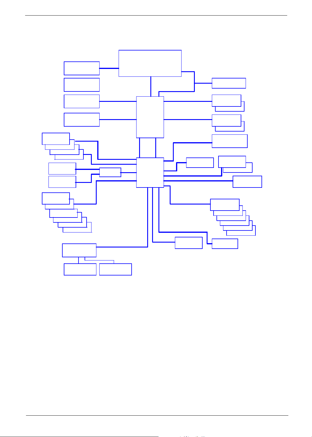
System Block Diagram
VRD 11
4 Phase PWM
Intel ADD2/+ Card
or
Back Panel
USB2.0 Port 0
USB2.0 Port 1
USB2.0 Port 2
USB2.0 Port 3
Back Panel
1394a Port 1
Front Panel
1394a Port 2
Header
USB2.0 Port 4
USB2.0 Port 5
USB2.0 Port 6
USB2.0 Port 7
USB2.0 Port 8
PCI Express x 16
External Graphics
Card
VGA Connector
USB2.0 Port 9
Super I/O
ITE8718
PCI Express x16 Port
Direct Media Interface (DMI)
TI43AB23
4 Lanes
PCI I/F
LPC I/F
Cedar Mill, Presler ,
Conroe & Allendale
LGA775 Processor
Socket T
GMCH
Broadwater
Controller Link
ICH8
1066/800/533 FSB
DDR2 533/667/800
DDR2 533/667/800
PCI Express x1 port
LPC I/F
Firmware HUB
Channel A DDR2
Channel B DDR2
SPI Flash
(BIOS)
PCI Express x1 port
Serial ATA
SATA Connector 1
AHCI, RAID0,1,5,10
SATA Connector 2
HDA Codec
Realtek ALC888
CK-505 Clock
DIMM1
DIMM2
DIMM1
DIMM2
LAN NINEVEH LAN
PCI Slot 1
PCI Slot 2
PCI Express x1
Slot 1
Ş
SATA Connector 3
SATA Connector 4
SATA Connector 5
ESATA Connector 6
Serial/LPT/KB/MS
Floppy
Drive Connector
Chapter 1 5
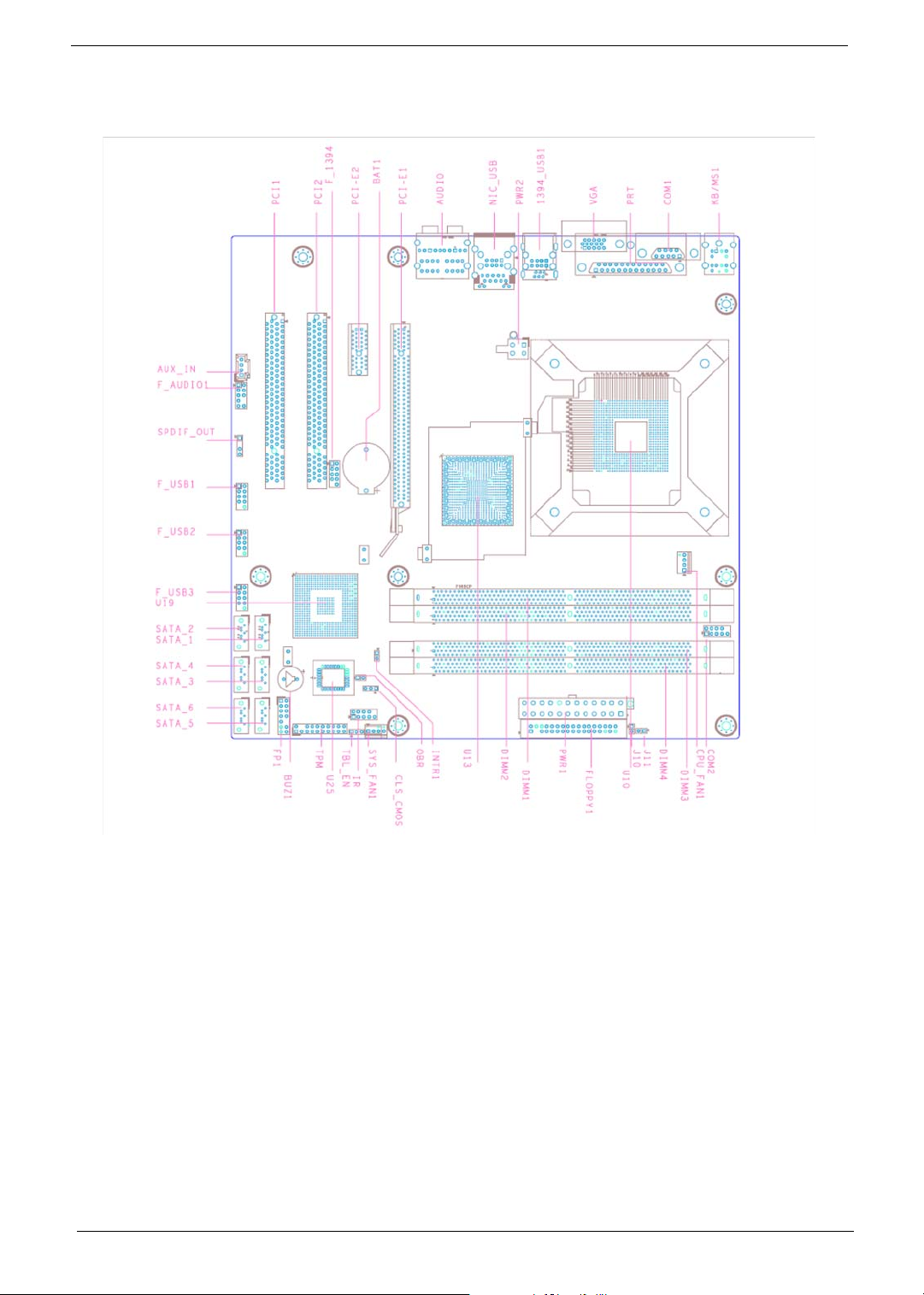
Main Board Layout
1 CPU_FAN1 CPU fan header 24 BIOS_SEL1 SPI & FWH BIOS select
2 COM2 COM Header 2 25 PWR2 4 pin power connector
3 J11 Acer special requirement 26 KB/MS1 Keyboard & Mouse PS2 port
4 J10 Acer special requirement 27 COM1 COM port
5 PWR1 24 pin power connector 28 PRT Printer port
6 FLOPPY1 Floppy connector 1 29 VGA VGA port
7 SYS_FAN1_1 System fan header 1_1(3
pin)
8 CLR_CMOS Clear CMOS 31 NIC_USB Lan and USB*2 port
9 OBR One Button Recovery 32 Audio Audio port
10 INTR1 Chassis Intruder 33 PCI-E1 PCI-Express X16 connector
11 FP1 Front Panel Switch/LED 34 BAT1 Battery connector
12 TPM Trusted Platform Module
Interface
30 1394_USB1 1394 and USB*2 ports
35 PCI-E2 PCI-Express X1 connector
6 Chapter 1

13 SATA_5 SATA data transfer
connector 5
14 SATA_6 SATA data transfer
connector 6
15 SATA_3 SATA data transfer
connector 3
16 SATA_4 SATA data transfer
connector 4
17 SATA_1 SATA data transfer
connector 1
18 SATA_2 SATA data transfer
connector 2
19 F_USB3 Front panel USB header 3 42 DIMM1,DIMM2,DIM
20 F_USB2 Front panel USB header 2 43 IR Infrared function header
21 F_USB1 Front panel USB header 1‘ 44 FLOPPY1 Floopy connector
22 F_AUDIO1 Front panel Audio header 45 BUZ1 Buzzer
23 AUX_IN Audio Aux input
36 F_1394 Front 1394 header
37 PCI1, PCI2 PCI connector
38 U25 FWH BIOS socket
39 U19 ICH8 series south bridge
40 U13 965 series nouth bridge
41 U10 LGA775 CPU socket
DDR2 memory connector
M3,DIMM4
Chapter 1 7
Your Acer Desktop tour
After knowing your computer features, let us show you around your new Veriton series computer.
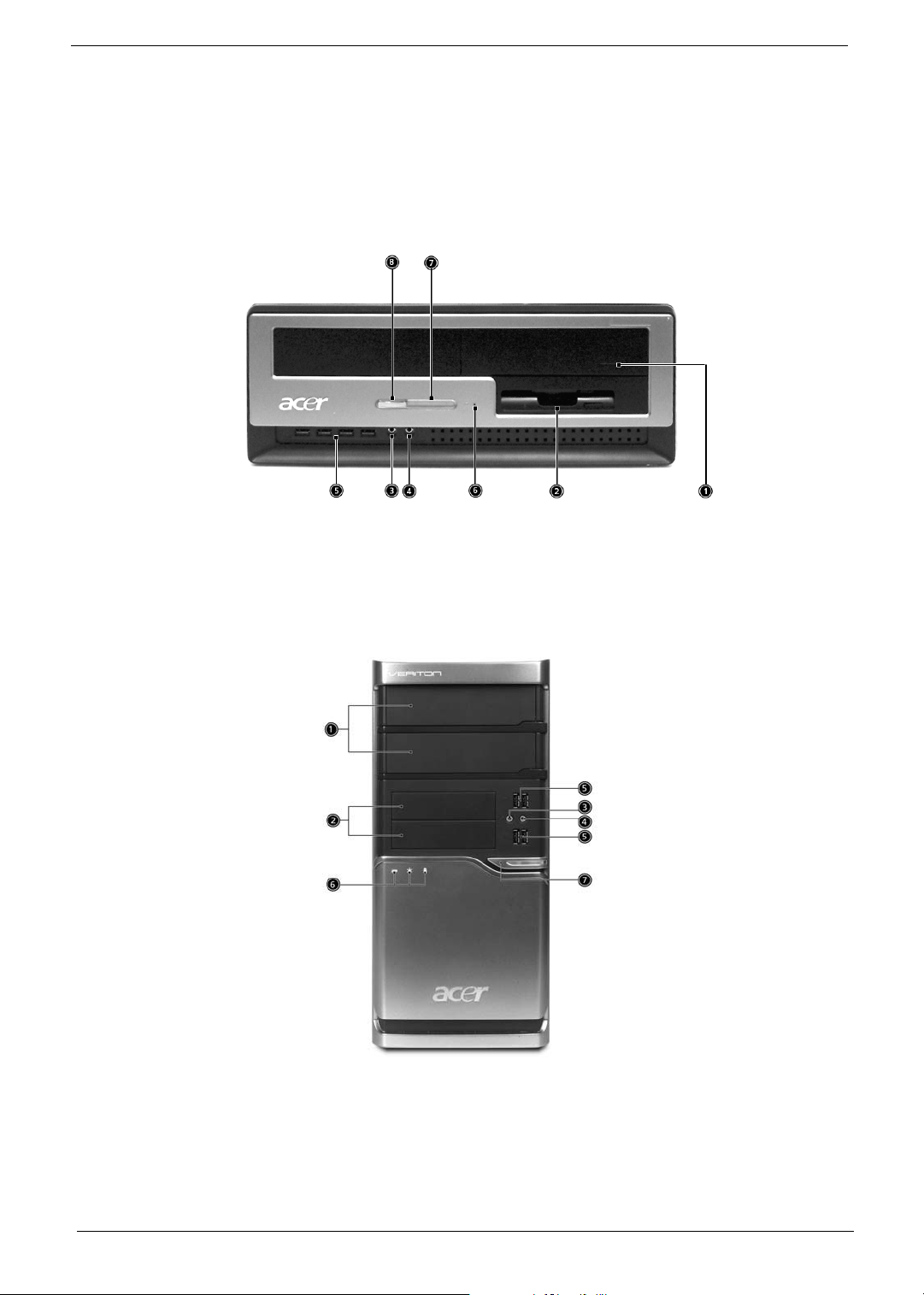
Front panel
Veriton 5900Pro front view
Veriton 6900Pro front view
8 Chapter 1
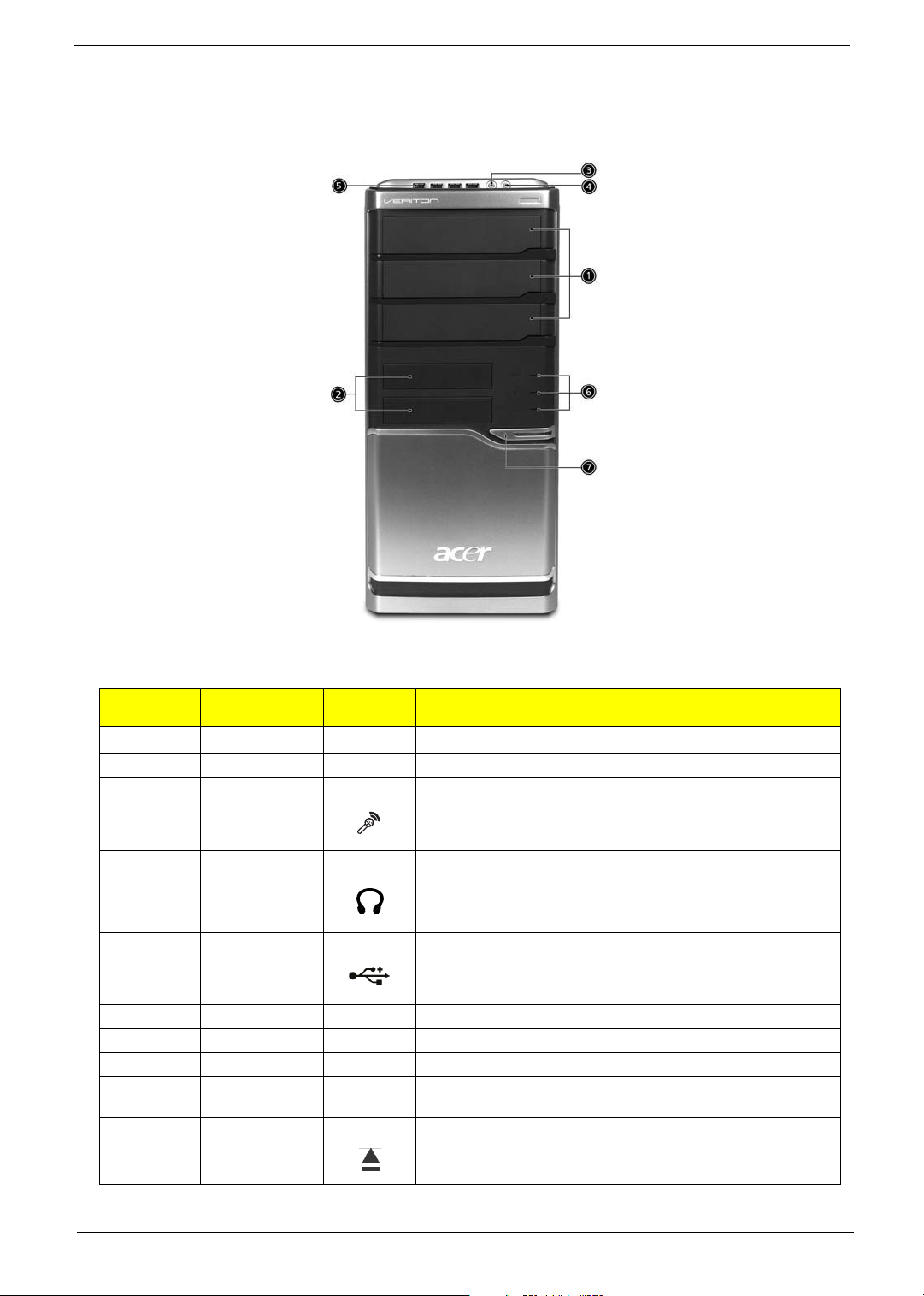
Veriton 7900Pro front view
Ver ito n
5900Pro
1 1 5.25” drive bay(s)
2 2 3.5 floppy drive
3 3 Microphone-in jack
4 4 Speaker-out/line-out
5 5 USB ports Connect to USB 2.0 devices (e.g., USB
6 Hardware reset button
7 6 Indicators
8 7 Power button Power on or off the system.
Veriton 6900Pro/
7900Pro
1 Optical disk drive (for
2 Eject button Ejects optical disks.
Icon Component Description
Accepts input from external microphones.
(front)
Connects to audio line-out devices (e.g.,
port
selected models)
speakers).
mouse, USB camera).
Accepts CDs or DVDs.
Chapter 1 9
3 Power button Power on or off the system.
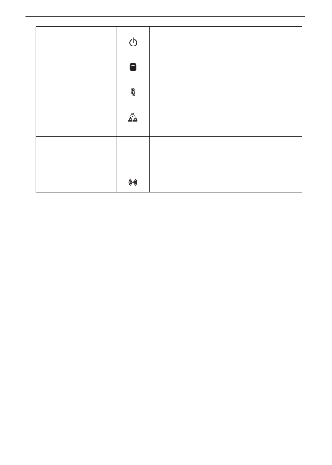
Icon Component Icon Component
4 Hard disk drive
indicator
5 Optical disk drive
indicator
6 LAN indicator Press to enable/disable Wireless function.
7 USB ports
8 Microophone-in jack
(front)
9 Headphone/Speaker-
out/line-out port
10/11 Line-in jack Accepts audio line-in devices (e.g., audio
Lights to indicate hard disk drive status.
Lights to Indicate optical disk drive status.
Lights to indicate the status of wireless
LAN communications.
CD player, stereo walkman).
10 Chapter 1
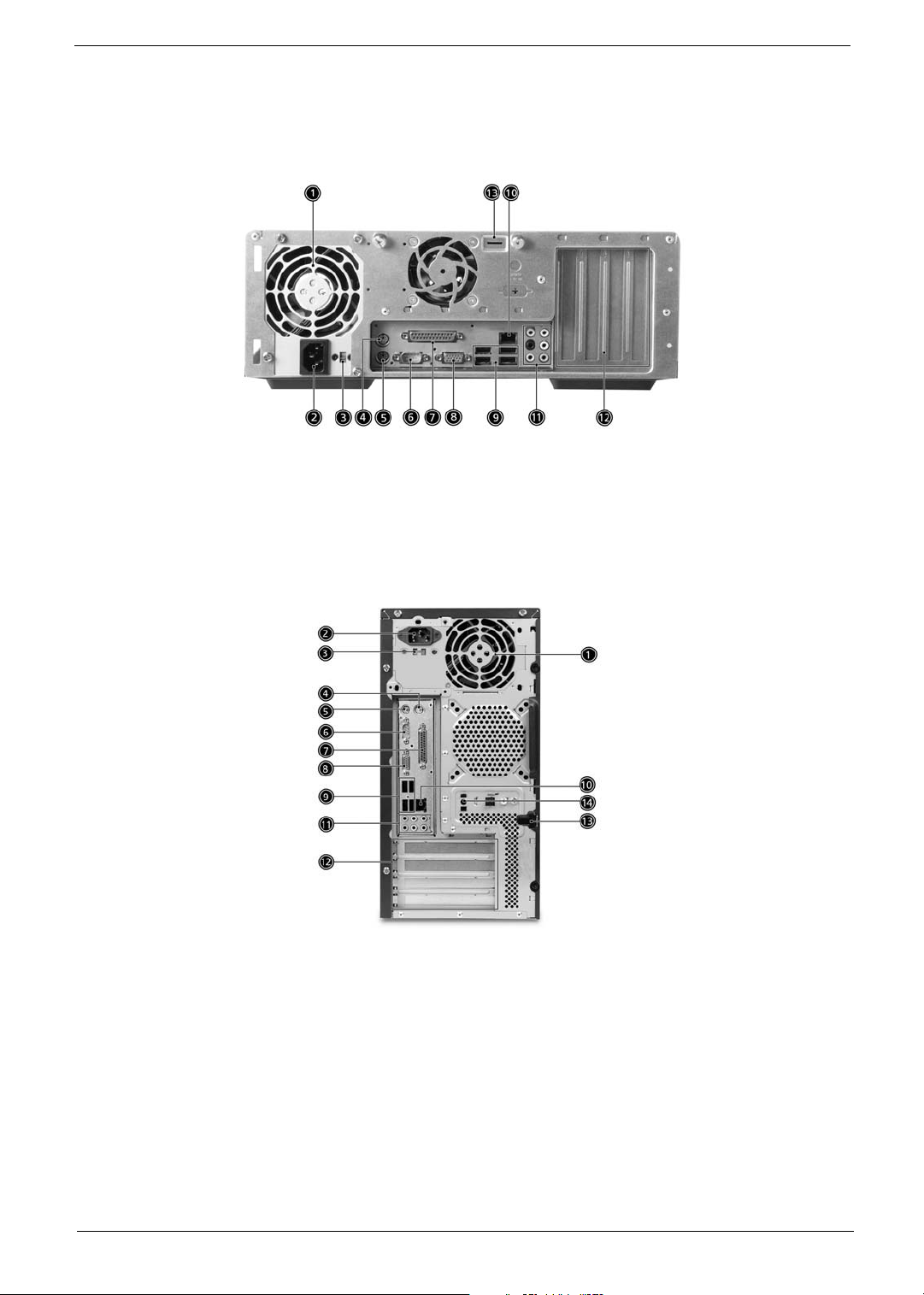
Rear panel
Veriton 5900Pro rear view
Veriton 6900Pro rear view
Chapter 1 11
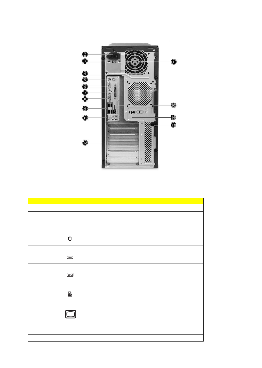
Veriton 7900Pro rear view
Icon Component
Veriton
5900Pro/6900Pro/7900Pro
Icon Component
Veriton
5900Pro/6900Pro/7900Pro
Icon Component
Veriton
5900Pro/6900Pro/7900Pro
Icon Component
Veriton
5900Pro/6900Pro/7900Pro
# Icon Component Description
1 Power supply
2 Power coard socket Connects to a power cord.
3 Voltage selector switch
4 PS/2 mouse port Accepts input from PS/2 mouses.
5 PS/2 keyboard port Accepts input from PS/2 keyboards.
6 Serial port Connects to a serial device (e.g., external
serial mouse or keyboard).
7 Parallel/printer port Connects to a parallel device (e.g., printer).
8 CRT/LCD monitor port Connects to a display device (e.g., external
monitor, LCD projector).
9 USB ports Connect to USB 2.0 devices (e.g., USB
10
mouse, USB camera).
12 Chapter 1
11
Icon Component Icon Component
12
13
14
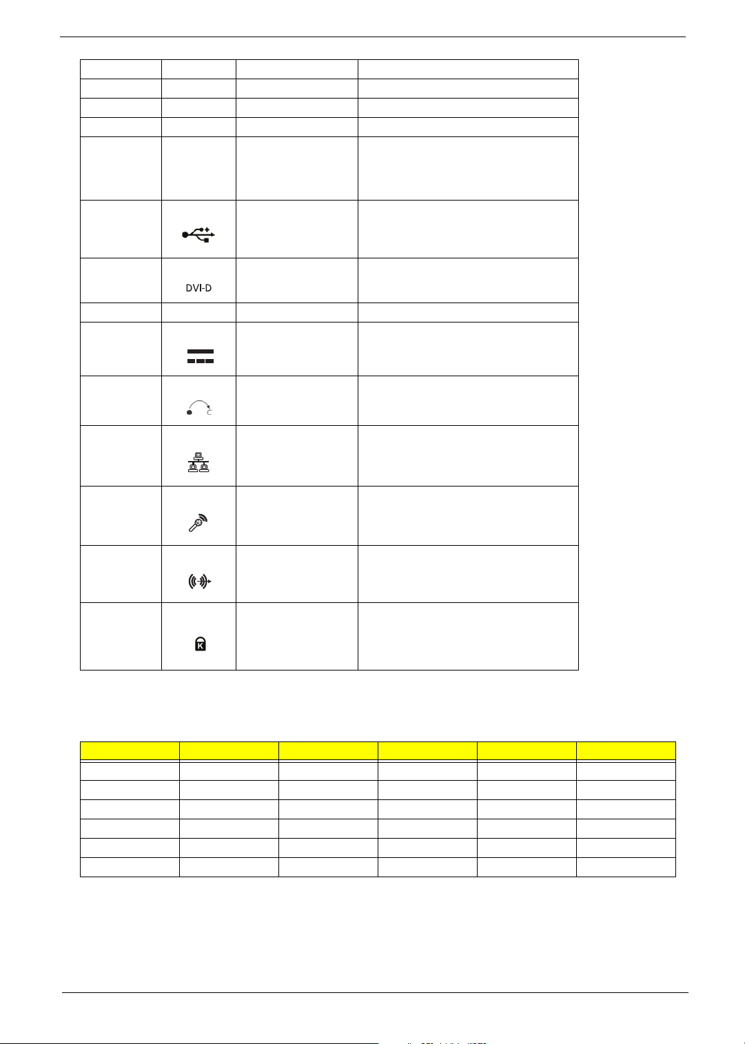
1 Ventilation slots Enable the computer to stay cool, even
after prolonged use.
Note: Do not cover or obstruct the opening
of the fan.
2 USB ports
3 DVI por Supports digital video connections.
4 CRT/LCD monitor port
5 DC-in jack Connects to an AC adapter.
6 OBR (One Button
Recovery) button
7 Network port Lights to indicate the status of wireless
LAN communications.
8 Mic-in jack Accepts input from external microphones.
9 Line-out jack
10/11 Kensington lock Connects to a Kensington-compatible
Audio Jack Function Table
Color/Use Headphone 1.1 CH 3.1 CH 5.1 CH 7.1 CH
Blue Line-in Line-in Line-in Line-in Line-in
Green Headphone Line-out Front Front Front
Pink N/A Mic-in Mic-in Mic-in Mic-in
Orange N/A N/A N/A Rear Rear
Black N/A N/A Center & woofer Center & woofer Center & woofer
Gray N/A N/A N/A N/A Side
computer security lock.
Chapter 1 13
System Peripherals
Note:
The Aspire T630 and AcerPower F3 computer consist of the system itself, and system peripherals, like a
mouse, keyboard and a set of speakers (optional). This section provides a brief description of the basic
system peripherals.
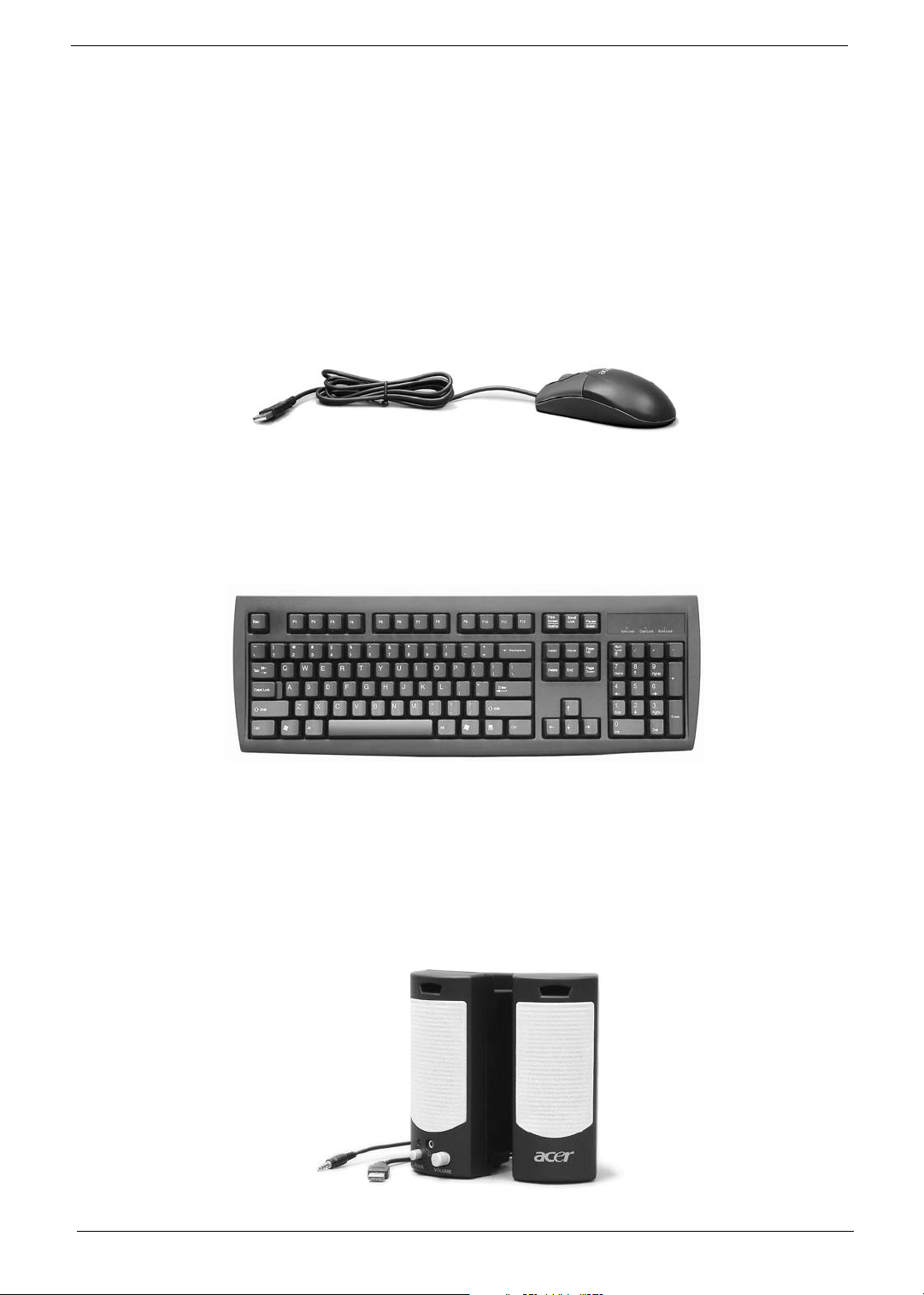
Mouse (PS/2 or USB, manufacturing option)
The included mouse is a standard two-button wheel mouse. Connect the mouse to the PS/2 mouse port or
USB port on the back panel of the system.
Keyboard (PS/2 or USB, manufacturing option)
Connect the keyboard to the PS/2 keyboard port or USB port on the back panel of the system.
Speakers
For systems bundled with speakers, before powering on the system, connect the speaker cable to the audio
out (external speaker) port on the back panel of the system.
For more detailed information about the speakers, please refer to the included operating instructions.
NOTE: speakers are optional and the appearance might be different depending on the actual product.
14 Chapter 1
Acer Empowering Technology
Acer’s innovative Empowering Technology makes it easy for you to access frequently used functions and
manage your new Acer notebook. It features the following handy utilities:
• Acer eSettings Management accesses system information and adjusts settings easily.
• Acer eLock Management (for slected models) limits access to external storage media.
• Acer eDataSecurity Management protects data with passwords and advanced encryption algorithms.
• Acer ePerformance Management improves system performance by optimizing disk space, memory and
registry settings.
• Acer eAcoustics Management offers a useful tool to balance your computing power needs with your
desired level of quietness.
• Acer eRecovery Management backs up and recovers data flexibly, reliably and completely.
• Acer eProtection Management provides exceptional protection against viruses and other malware.
For more information, press the < > key to launch the Empowering Technology menu, then click on the
appropriate utility and select the Help or Tutorial function.
Empowering Technology password
Before using Acer eLock Management and Acer eRecovery Management, you must initalize the Empowering
Technology password. Right-click on the Empowering Technology toolbard and select “Password Setup” to do
so. If you do not initialize the Empowering Technology password, you will be prompted to do so when running
Acer eLock Management or Acer eRecovery Management for the first time.
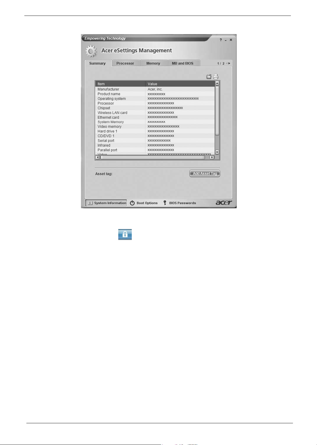
Acer eSettings Management
Acer eSettings Management allows you to inspect hardware specifications, change BIOS passwords or other
Windows settings, and to monitor the system health status.
Acer eSettings Management also:
• Provides a simple graphical user interface for navigating.
• Displays general system status and advanced monitoring for power users on Acer computer.
Chapter 1 15
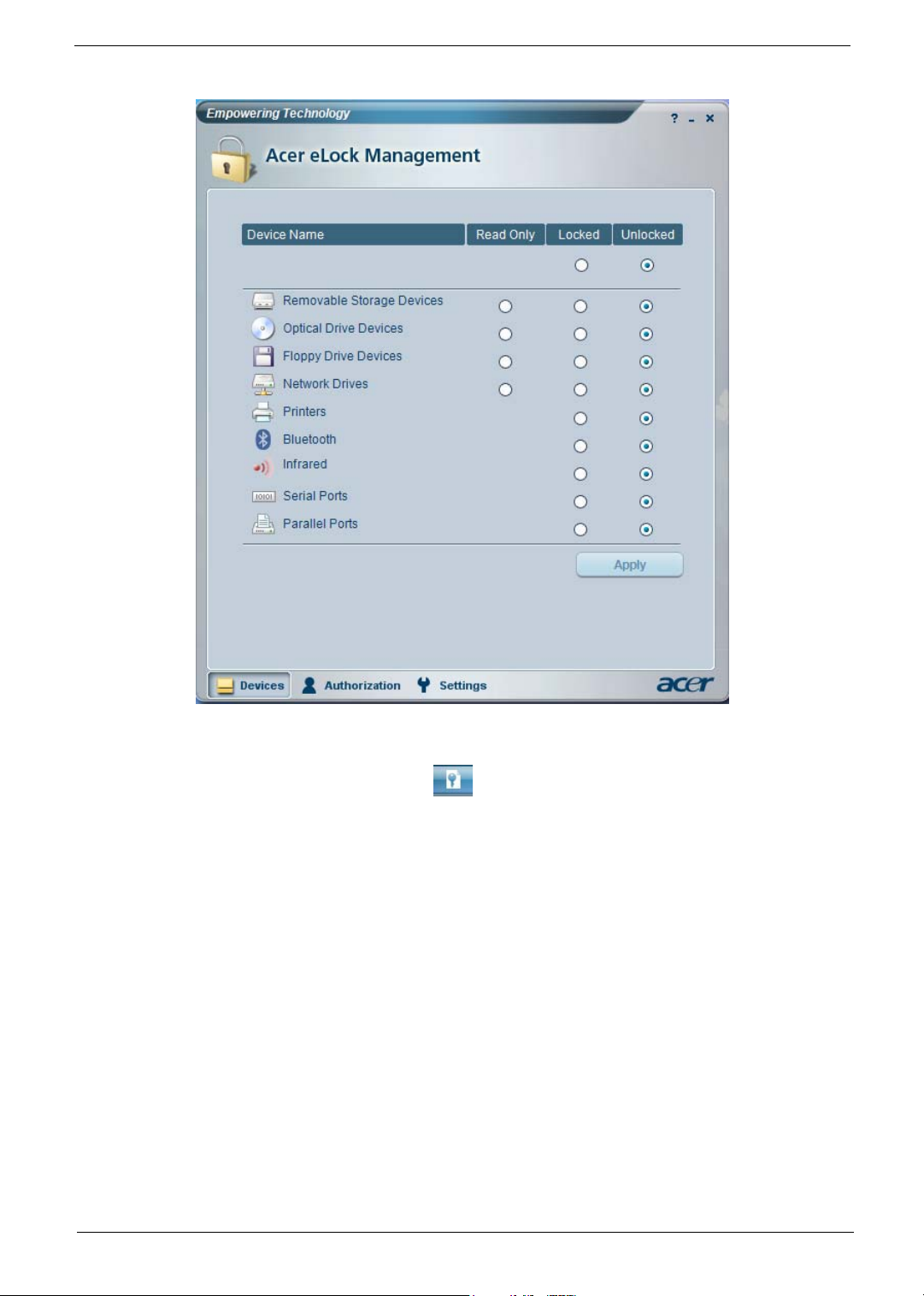
Acer eLock Management
Acer eLock Management is a security utility that allows you to lock your removable data, optical and floppy
drives to ensure that data can’t be stolen while your notebook is unattended.
• Removable data devices - includes USB disk drives, USB pen drives, USB flash drives, USB MP3 drives,
USB memory card readers, IEEE 1394 disk drives and any other removable disk drives that can be
mounted as a file system when plugged into the system.
• Optical drive deivces - includes any kind of CD-ROM or DVD-ROM drives.
• Floppy disk drives - 3.5-inch disks only.
• Interfaces - includes serial ports, parallel port, infrared (IR), and Bletooth.
To activate Acer eLock Management, a password must be set first. Once set, you can apply locks to any of the
devices. Lock(s) will immediately be set without any reboot necessary, and will remain locked after rebooting,
until unlocked.
NOTE: If you lose your password, there is no method to reset it except by reformatting your notebook or taking
your notebook to anAcer Customer Serivce Center. Be sure to remember or write down your password.
16 Chapter 1
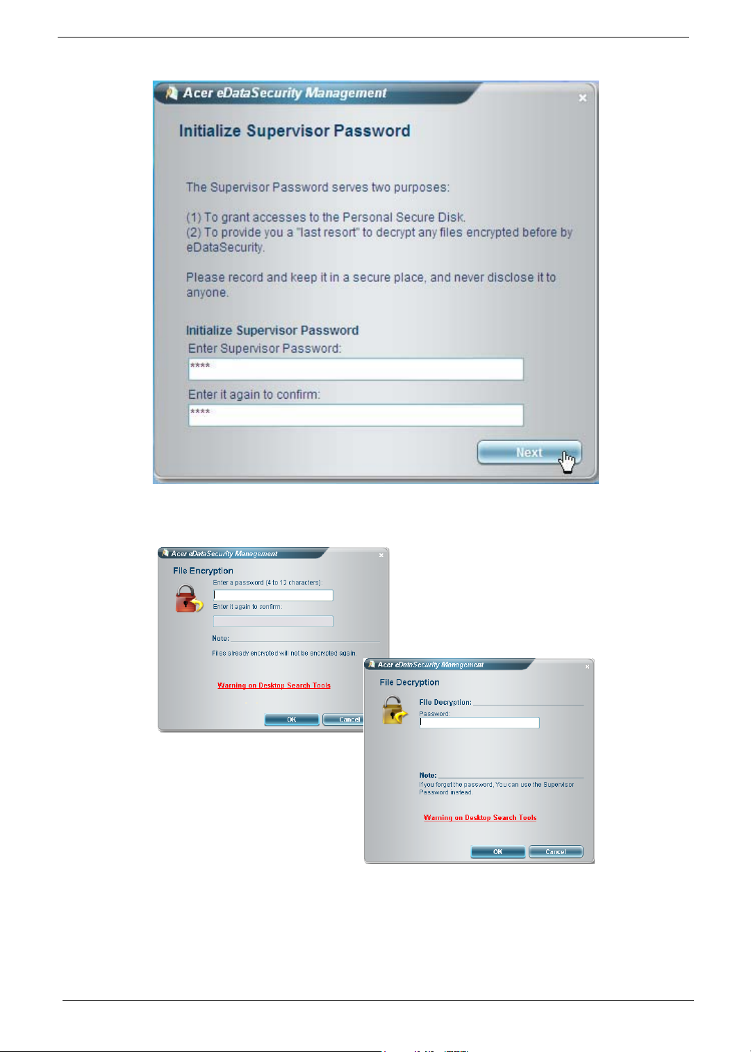
Acer eDataSecurity Management
Acer eDataSecurity Management is handy file encryption utility that protexts your files from being accessed by
unauthorized persons. It is conveniently integrated with Windows explorer as a shell extension for quick and
easy data encryption/decryption and also supports on-the-fly file encryption for MSN Messager and Microsoft
Outlook.
The Acer eDataSecurity Management setup wizard will prompt you for a suvervisor password and default
encryption. This encryption will be used to encrypt files by default, or you can choose to enter your won filespecific password when encrypting a file.
NOTE: The password used encrypt a file is the unique key that the system needs to decrypt it. If you lose the
password, the supervisor password is the only other key capable of decrypting the file. If you lose both
passwords, there will be no way to decrypt your encryped file! Be sure to safeguard all related
passwords!
Chapter 1 17
18 Chapter 1
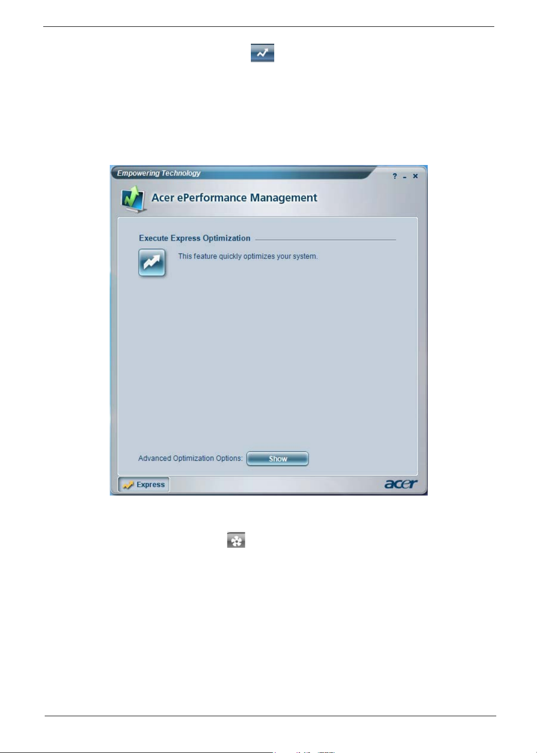
Acer ePerformance Management
Acer ePerformance Management is a system optimization tool that boosts the performance of your Acer
notebook. It provides and express optimization method to release unused memory and disk space quickly.
The user can also enable advanced options for full control over the following option:
• Memory optimization - releases unused memory and check usage.
• Disk optimization - removes unneeded items and files.
• Speed optimization - improves the usability and performance of your Windows XP system.
Acer eAcoustics Management
Acer eAcoustics Management offers you a useful tool to balance your computing power needs with your
desired level of quietness. By reducing the processor speed for tasks that require less processing, the CPU
and system fans can run slower, thus reducing the amount of sound generated by tehse components.
Using Acer eAcoustics Management
To launch Acer eAcoustics Management
• Click on the Acer eAcoustics Management icon in the Empowering Technology toolbard shown on your
desktop.
• From the Start menu, go to (All) Programs>Acer Empowering Technology>Acer eAcoustics
Management.
Chapter 1 19
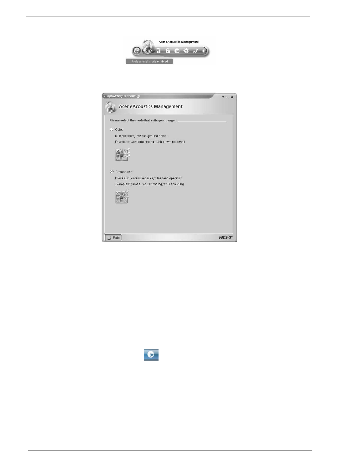
This will open Acer eAcoustics Management main page.
Acer eAcoustics Management Main Page
Listed on the main page are two options for Acer eAcoustics Management, labeled as Quiet and Professional.
Select the mode that suits your working requirements best, and exit the utility to apply the settings.
Quiet
Use this mode for tasks that require low processing power, like word processing, Web browsing, and instant
messaging. This mode creates the lowest audio disturbance.
Professional Mode
Use this mode for processing-intensive tasks, when you require full-speed operation.
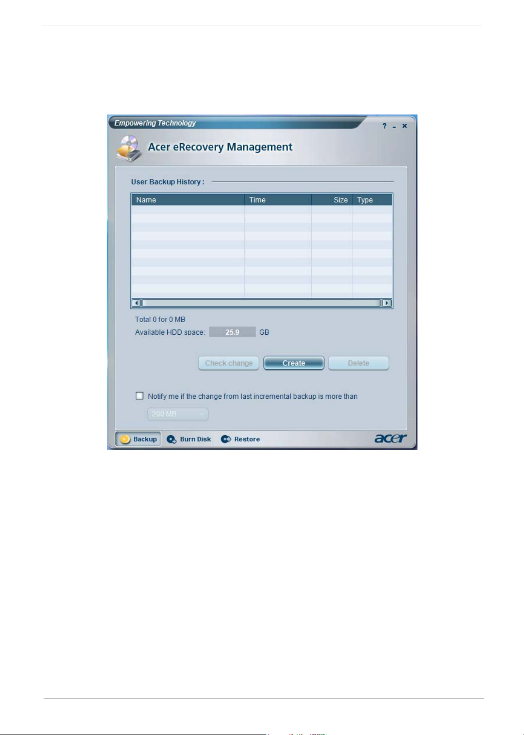
Acer eRecovery Management
Acer eRecovery Management is a powerful utility that does away with the need for recovery disks provided by
the manufacturer. The Acer eRecovery Management utility occupies space in a hidden partition on your
system’s HDD. User-created backups are stored on D:\ drive. Acer eRecovery Management provides you
with:
• Password protection.
• Recovery of applications and drivers.
• Image/data backup:
T Back up to HDD (set recovery point).
T Back up to CD/DVD.
20 Chapter 1
• Image/data recovery tools:
T Recover from a hidden partition (factory defaults).
T Recover from the HDD (most recent user-defined recovery point).
T Recover from CD/DVD.
For more information, please refer to “Acer eRecovery Management”
NOTE: If your computer did not come with a Recovery CD or System CD, please use Acer eRecovery
Management’s “System backup to optical disk” feature to burn a backup image to CD or DVD. To
ensure the best results when recovering your system using a CD or Acer eRecovery Management,
detach all peripherals (except the external Acer ODD, if your computer has one), including your Acer
ezDock.
Chapter 1 21
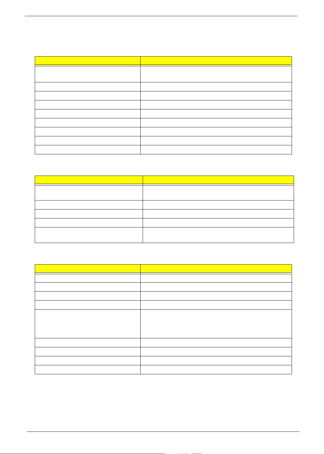
Hardware Specifications and Configurations
System Board Major Chip
Item Specification
System Core Logic North bridge: Intel (R) Q965
South bridge: Intel (R) ICH8DO
Super I/O Controller ITE IT8718DX
LAN Controller Intel (R) 82566DM
Memory Controller Built-in north bridge: Intel Q965
SATA Controller Built-in ICH8DO
1394 Controller TI TSB43AB23PDTG4
Audio Controller Realtek ALC888
VGA Controller Built-in Intel (R) Q965 (GMCH)
Keyboard Controller ITE IT8718DX
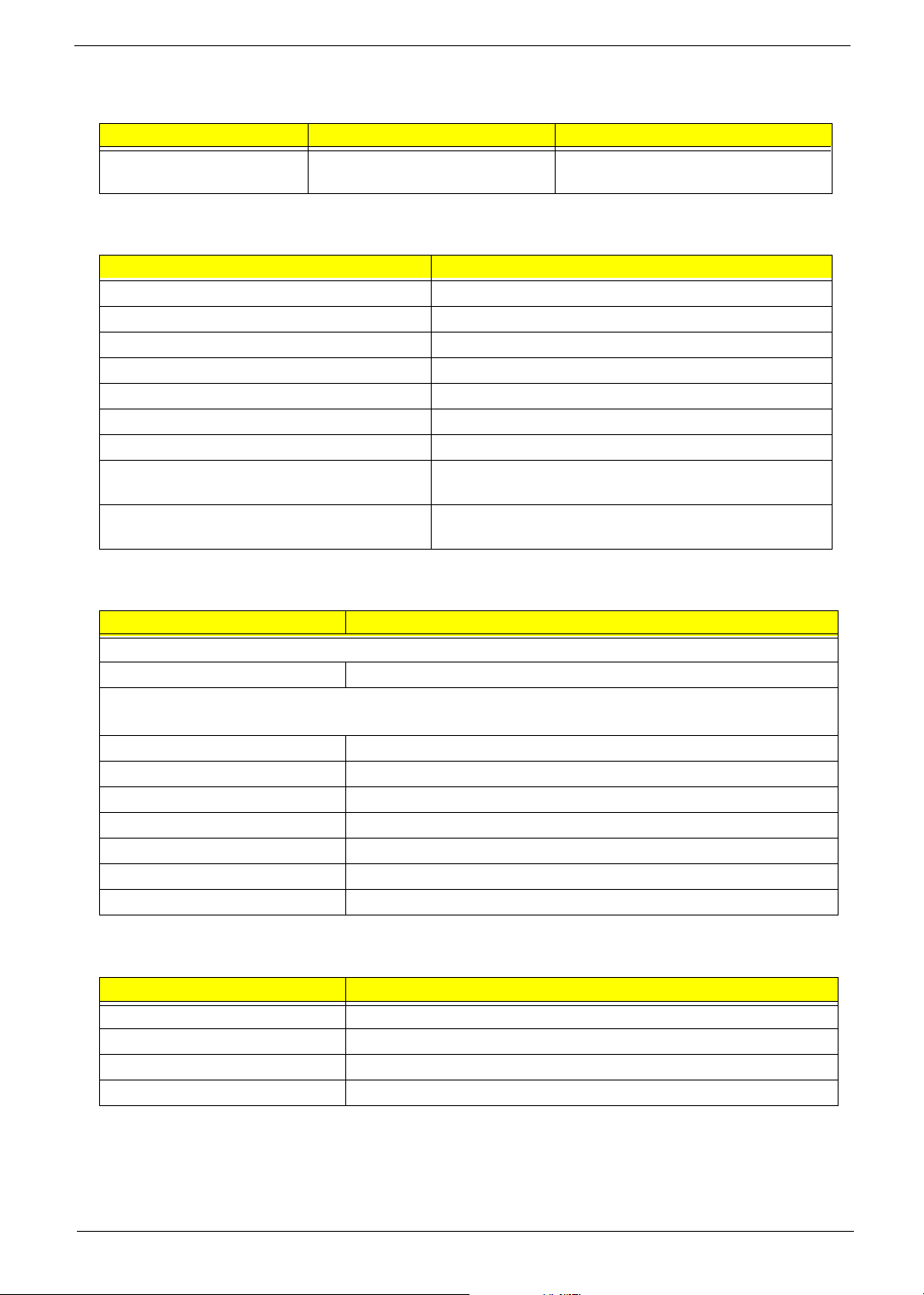
Processor
Item Specification
Typ e
Slot Socket 940
Speed Depends on CPU, which is local configured
Bus Frequency 533/800/1066 MHz
Voltage Processor voltage can be detected by any system without
Supports AMD mobile Athlon 64 (62W) M2
Supports AMD Sempron-D (62W) M2
setting any jumper
BIOS
Item Specification
BIOS code programmer Award
BIOS version
BIOS ROM size 4MB
BIOS ROM package 32-pin PLCC package
Support protocol PCIX 1.0,PCI 2.2,APM 1.2,VESA/DPMS (VBE/PM V1.1),
SMBIOS 2.3, E-IDE 1.1, ACPI 1.0b,ESCD1.03, PnP 1.0a,
Bootable CD-ROM 1.0, USB 1.1~ USB 2.0, UHCI 1.0, ANSI
ATA 3.0 ATAPI
Boot from CD-ROM feature Yes
Support to LS-120 drive Yes
Support to BIOS boot block feature Yes
BIOS Password Control Yes
22 Chapter 1
BIOS Hotkey List
Hotkey Function Description
c Enter BIOS Setup Utility Press while the system is booting to
enter BIOS Setup Utility.
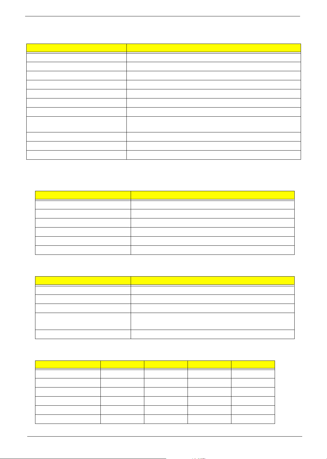
System Memory
Item Specification
Memory Slot Number 4 Slots
Supported Memory Size per Slot 256 MB ~ 1GB
Supported Maximum Memory Size 4GB
Supported Memory Speed 533/667/800 MHz
Supported memory voltage 1.8V
Support memory module package 240-pin DIMM
Support to parity check feature Yes
Support to Error Correction Code (ECC)
feature
Memory module combinations You can install memory modules in any combination as
Cache Memory
Yes
long as they match the above specifications.
Item Specification
First-Level Cache Configurations
Cache function control Enable/Disable by BIOS Setup
Second-Level Cache Configurations
The information below is only applicable to system installed with a Pentium 4 processor
Tag RAM Location On Processor
L2 Cache RAM Location On Processor
L2 Cache RAM type PBSRAM (Pipelined-burst Synchronous RAM)
L2 Cache RAM size Depends on CPU, which is local configured
L2 Cache RAM speed Full of the processor core clock frequency (Advanced Transfer Cache)
L2 Cache function control Enable/Disable by BIOS Setup
L2 Cache scheme Fixed in write-back
LAN Interface
Item Specification
LAN Controller Intel (R) Nineveh 82566DM
LAN Controller Resident Bus PCI Express Bus
LAN Port ONE RJ-45 on board
Function Control Enable/Disable by BIOS Setup
Chapter 1 23
IDE Interface
Item Specification
IDE Controller Built-in nVidia MCP51
IDE Controller Resident Bus PCI bus
Number 40 pin PATA slot 1
T Device Type Support HDD, CD-ROM, CD-RW, DVD-ROM,Combo,DVD burner
T Transfer Rate Support PIO 0/1/2/3/4
T ATA Mode 33/66/100
Number STAT IDE slot 4
T Device Type Support HDD,CD-ROM,CD-RW,DVD-ROM,DVD-RW,DVD+RW,DVD
Dual,DVD Supermultiplus
Supports LS-120 Yes
Supports bootable CD-ROM Yes
Function Control Enable/Disable by BIOS setup
Serial Port (No serial port for this model)
Item Specification
Serial port controller LPC47M182
Serial port controller resident bus LPC Bus
Number of serial port 1
Serial port location Rear panel
16550 UART support Yes
Connector type 9-pin D-type female connector
USB Port
Item Specification
Universal HCI USB 2.0/1.1
Controller Built-in nVidia MCP51
Number of the connectors 8
Location Rear : 4
Front : 4
USB Class Support legacy keyboard for legacy mode
Wake-up Event Specifications
Device S1 S3 S4 S5
Power Button
PS2 Keyboard
USB Keyboard
PME
WOR (wake on Ring)
RTC (real time clock)
Enabled Enabled Enabled Enabled
Disabled Disabled Disabled Disabled
Disabled Disabled N/A N/A
Disabled Disabled Disabled Disabled
Disabled Disabled Disabled Disabled
Disabled Disabled Disabled Disabled
24 Chapter 1
 Loading...