

Page 1
90$6\VWHP%RDUG
User’s Guide
Page 2

&RS\ULJKW
Copyright 1998 by this company. All rights reserved. No part of
this publication may be reproduced, transm itted, transcribed, stored in
a retrieval system, or translated into any language or computer
language, in any form or by any means, electronic, mechanical,
magnetic, optical, chemical, manual or otherwise, without the prior
written permission of this company.
'LVFODLPHU
This company makes no representations or warranties, either
expressed or implied, with respect to the contents hereof and
specifically disclaims any warranties, m erchantability or f itness for any
particular purpose. Any software described in this manual is sold or
licensed "as is". Should the programs prove defective following their
purchase, the buyer (and not this company, its distributor, or its dealer)
assumes the entire cost of all necessary servicing, repair, and any
incidental or consequential damages resulting from any defect in the
software. Further, this company reserves the right to revise this
publication and to make changes from time to time in the contents
hereof without obligation to notify any person of such revision or
changes.
All brand and product names mentioned in this manual are trademarks and/or
registered trademarks of their respective holders.
ii
Page 3

,03257$176$)(7<
,16758&7,216
1. Read these instructions carefully. Save these instructions for
future reference.
2. Follow all warnings and instructions marked on the product.
3. Unplug this product from the wall outlet before cleaning. Do not
use liquid cleaners or aerosol cleaners. Use a damp cloth for
cleaning.
4. Do not use this product near water.
5. Do not place this product on an unstable cart, stand, or table.
The product may fall, causing serious damage to the product.
6. Slots and openings in the cabinet and the back or bottom are
provided for ventilation; to ensure reliable operation of the pr oduc t
and to protect it from overheating, these openings must not be
blocked or covered. The openings should never be block ed by
placing the product on a bed, sofa, rug, or other similar surface.
This product should never be placed near or over a radiator or
heat register, or in a built-in installation unless proper ventilation is
provided.
7. This product should be operated from the type of power indicated
on the marking label. If you are not sure of the type of power
available, consult your dealer or local power company.
8. This product is equipped with a 3-wire grounding-type plug, a plug
having a third (grounding) pin. This plug will only fit into a
grounding-type power outlet. This is a safety feature. If you are
unable to insert the plug into the outlet, contact your electrician to
replace your obsolete outlet. Do not defeat the purpose of the
grounding-type plug.
iii
Page 4

9. Do not allow anything to rest on the power cord. Do not locate
this product where persons will walk on the cord.
10. If an extension cord is used with this product, m ake sur e that the
total ampere rating of the equipment plugged into the ex tension
cord does not exceed the extension cord ampere rating. Also,
make sure that the total rating of all products plugged into the wall
outlet does not exceed 15 amperes.
11. Never push objects of any kind into this product through cabinet
slots as they may touch dangerous voltage points or short out
parts that could result in a fire or elec tric shock . Never s pill liquid
of any kind on the product.
12. Do not attempt to service this product yourself, as opening or
removing covers may expose you to dangerous voltage points or
other risks. Refer all servicing to qualified service personnel.
13. Unplug this product from the wall outlet and refer servicing to
qualified service personnel under the following conditions:
a. When the power cord or plug is damaged or frayed
b. If liquid has been spilled into the product
c. If the product has been exposed to rain or water
d. If the product does not operate nor mally when the operating
instructions are followed. Adjust only those controls that are
covered by the operating instructions since improper
adjustment of other c ontrols may result in damage and will
often require extensive work by a qualified technician to
restore the product to normal condition.
e. If the product has been dropped or the cabinet has been
damaged
f. If the product exhibits a distinct change in performance,
indicating a need for service
iv
Page 5

14. Replace the battery with the same type as the product's battery
we recommend. Use of another battery may present a ris k of f ire
or explosion. Refer battery replacement to a qualified
serviceman.
15. Warning! The battery may explode if not handled properly. Do
not recharge, disassemble, or dispose of it in fire. Keep away
from children and dispose of any used battery promptly.
16. Use only the proper type of power supply cord set (provided in
your keyboard/manual accessories box) for this unit. It should be
a detachable type: UL listed/CSA certified, type SVT/SJT, rated
6A 125V minimum, VDE approved or its equivalent. Maximum
length is 15 feet (4.6 meters).
v
Page 6

&'5206DIHW\:DUQLQJ
DANGER
INVISIBLE RADIATION WHEN OPEN.
AVOID EXPOSURE TO BEAM.
VORSICHT
UNSICHTBARE LASERSTRAHLUNG WENN GEÖFFNET.
NICHT IN DEN STRAHL SEHEN.
ATTENTION
RADIATION DU FAISCEAU LASER INVISIBLE. EN CAS
D’OUVERTURE. EVITER TOUTE EXPOSITION AUX RAYONS.
VARO
AVATTAESSA OLET ALTTIINA NÄKYMÄTTÖMÄLLE
LASERSÄTEILYLLE ÄLÄ KATSO SÄTEESEEN.
VARNING!
OSYNLING LASERSTRÄLNING NÄR DENNA DEL ÄR ÖPPNAD.
BETRAKTA EJ STRÄLEN.
VARNING
OSYNLING LASERSTRÄLNING NÄR DENNA DEL ÄR ÖPPNAD.
STIRRA EJ IN I STRÄLEN.
ADVARSEL
LASERSTRÄLING VED ÄBNING. SE IKKE IND I STRÄLEN.
CLASS 1 LASER PRODUCT
APPAREIL A LASER DE CLASSE 1
LASER KLASSE 1
LOUKAN 1 LASERLAITE
PRODUIT LASER
CATEGORIE 1
vi
Page 7

&DXWLRQRQ/LW KLXP%DWWHULHV
CAUTION
Danger of explosion if battery is incorrectly replaced. Replace only
with the same or equivalent type recommended by the manufacturer.
Discard used batteries according to the manufacturer’s instructions.
ADVARSEL!
Lithiumbatteri - Eksplosionsfare ved fejlagtig håndtering.
Udskiftning må kun ske med batteri af samme fabrikat og type.
Léver det brugte batteri tilbage til leverandøren.
ADVARSEL
Eksplosjonsfare ved feilaktig skifte av batteri.
Benytt samme batteritype eller en tilsvarende
type anbefalt av apparatfabrikanten.
Brukte batterier kasseres i henhold til fabrikantens instruksjoner.
VARNING
Explosionsfara vid felaktigt batteribyte.
Anvãnd samma batterityp eller en ekvivalent typ som
rekommenderas av apparattillverkaren.
Kassera anvãnt batteri enligt fabrikantens instruktion.
VAROITUS
Päristo voi räjähtää, jos se on virheellisesti asennettu.
Vaihda paristo ainoastaan laitevalmistajan suosittelemaan tyyppiin.
Hävitä käytetty paristo valmistajan ohjeiden mukaisesti.
VORSICHT!
Explosionsgefahr bei unsachgemäßen Austausch der Batterie Ersatz
nur durch denselben oder einem vom Hersteller empfohlenem
ähnlichen Typ. Entsorgung gebrauchter Batterien nach Angaben des
Herstellers.
vii
Page 8

)&&&ODVV%5DGLR )UHTXHQF\
,QWHUIHUHQFH6WDWHPHQW
Note:
This equipment has been tested and found to comply with the limits for
a Class B digital device, pursuant to Part 15 of FCC Rules. These
limits are designed to provide reasonable protection against harmful
interference in a residential installation. This equipment generates,
uses, and can radiate radio frequency energy and, if not installed and
used in accordance with the instructions, may cause harmful
interference to radio com munications. However, there is no guarantee
that interference will not occur in a particular installation. If this
equipment does cause harmful interference to radio or television
reception, which can be determined by turning the equipment off and
on, the user is encouraged to try to correct the interference by one or
more of the following measures:
1. Reorient or relocate the receiving antenna.
2. Increase the separation between the equipment and receiver.
3. Connect the equipment into an outlet on a circuit different from
that to which the receiver is connected.
4. Consult the dealer or an experienced radio/television technician
for help.
Notice 1:
The changes or modifications not expressly approved by the party
responsible for com pliance could void the user's authority to operate
the equipment.
Notice 2:
Shielded interface cables, if any, must be used in order to com ply with
the emission limits.
viii
Page 9
$ERXWWKLV0DQXDO
Purpose
This user’s guide aims to give you all the necessar y information about
the system board, such as system board layout, onboard components ,
jumper settings, cac he and memory configurations, and other internal
devices.
Conventions
The following are the conventions used in this manual:
NOTE
Gives bits and pieces of additional
information related to the current
topic.
WARNING
Alerts you to any damage that
might result from doing or not doing
specific actions.
CAUTION
Gives precautionary measures to
avoid possible hardware or
software problems.
IMPORTANT
Reminds you to do specific actions
relevant to the accomplishment of
procedures.
TIP
Tells how to accomplish a
procedure with fewer steps through
little shortcuts.
ix
Page 10

7DEOHRI&RQWHQWV
1 Major Components.........................................................2
2 System Board Layout.....................................................4
3 Jumpers and Connectors...............................................5
3.1 Jumper and Connector Locations...................5
3.2 Jumper Settings..............................................6
3.3 Onboard Connector Functions........................8
4 Installation Precautions..................................................9
4.1 ESD Precautions.............................................9
4.2 Pre-installation Instructions.............................9
4.3 Post-installation Instructions.........................10
5 Memory Configurations................................................11
5.1 Installing a DIMM..........................................11
5.2 Removing a DIMM........................................12
5.3 Reconfiguring the System.............................13
6 Second-level Cache.....................................................14
7 Upgrading the CPU......................................................14
7.1 Removing the CPU.......................................14
7.2 Installing the Upgrade CPU ..........................15
8 IDE Hard Disk Sup port................................................17
9 Video Function.............................................................18
10 Audio Function.............................................................20
11 Expansion Cards..........................................................21
11.1 Installing a PCI Card.....................................21
11.2 Installing ISA Cards ......................................22
12 USB..............................................................................23
13 Wireless Communication Feature ...............................24
x
Page 11

14 Hardware Monitoring Function.....................................24
15 Wake-on Ring-in Function...........................................24
16 Wake-on LAN Function ...............................................25
17 Error Messages ...........................................................25
17.1 Software Error Messages.............................25
17.2 System Error Messages...............................25
17.3 Correcting Error Conditions..........................28
List of Figures
1 System Board Layout.....................................................4
2 System Board Jumper and Connector Locations..........5
3 Installing a DIMM .........................................................12
4 Removing a DIMM.......................................................13
5 Removing the CPU......................................................15
6 Installing a CPU ...........................................................16
7 Attaching the Heatsink and Fan to the CPU................16
8 Connecting External Audio Peripherals .......................20
9 Installing a PCI Card....................................................21
10 Installing an ISA Card ..................................................23
xi
Page 12

List of Tables
1 Jumper Settings.............................................................6
2 System Board Connectors .............................................8
3 Memory Configurations ................................................11
4 Second-level Cache Configurations.............................14
5 IDE Hard Disk Configuration........................................17
6 Supported Video Resolutions.......................................18
7 System Error Messages...............................................26
xii
Page 13

V70MA System Board
The V70MA is an all-in-one, high-performance system board that
supports the Intel Pentium processor with MMX (MultiMedia
eXtensions) technology. The MMX feature enables the system to
handle multimedia functions and enhance the performance of 32-bit
applications.
The system memory is upgradable to 256 MB via the onboard two
168-pin DIMM (Double In-line Memory Module) sockets. These
sockets accommodate 8-, 16-, 32-, 64- and 128-MB DIMMs. The
system board also comes with 512-KB second-level cache already
integrated in the CPU.
To fully support multimedia func tions, the board incorporates a highperformance 3-D video controller with AGP (Accelerated Graphics
Port) feature, 2- or 4-MB SGRAM (Synchronous Graphics Random
Access Memory), and a 3-D audio controller.
Onboard I/O (input/output) interfaces are comprised of two UART
(Universal Asynchronous Receiver-Transmitter) 16C550 serial
interfaces (one port and one connector), a parallel port with SPP
(Standard Parallel Port)/ECP (Extended Capabilities Port)/EPP
(Enhanced Parallel Port) support, and PS/2 keyboard and mouse
ports. Two USB (Universal Serial Bus) ports, one VGA (Video
Graphics Accelerator) por t, one Feature connec tor, one Mic rophone-in
port, one Line-in port, one Line-out port, and one Game/MIDI (Musical
Instrument Digital Interface) por t are als o added to the boar d design to
enable the system to support additional peripherals.
For expansion, the board comes with two ISA (Industry Standard
Architecture) slots and one PCI (Peripheral Component Interface) slot.
Special features such as PnP (Plug-and-Play) support, Power
Management, W ireless Communic ation, Hardware Monitoring, W akeon Ring, and Wake-on LAN (Local Ar ea Network) func tions are also
supported. These functions are individually discussed in this chapter.
V70MA System Board 1
Page 14

The system is fully compatible with MS-DOS V6.X, OS/2, SCO UNIX,
Windows NT, and Windows 95/98 operating systems.
1 Major Components
The system board has the following major components:
A Zero Insertion Force (ZIF) CPU socket that accommodates
•
Intel, AMD, or Cyrix/IBM Pentium CPU with MMX technology,
running at 233, 250, 266, 300, 333, or 350 MHz
Two DIMM sockets that accept 8-, 16-, 32-, 64-, and 128-MB
•
Standard DRAMs, with Parity Check or Error Correction Code
(ECC) feature. These sockets allow memory upgrade of up to
256 MB
512-KB second-level cache
•
PCI local bus IDE (Integrated Device Electronics) controller
•
3-D audio controller
•
AGP-compliant 3-D video graphics accelerator with 2- or 4-MB
•
SGRAM
One Feature connector
•
One Wake-on LAN connector
•
One Modem ring-in connector
•
One CD-in connector
•
One PCI audio upgrade connector
•
One Voice Modem connector
•
One IrDA (InfraRed Data Association) connector for Wireless
•
Communication support
Two PCI enhanced IDE interfaces that support up to four IDE
•
devices
External ports
•
PS/2 keyboard and mouse ports
•
2 User’s Guide
Page 15

• One buffered high-speed serial port
• One SPP/ECP/EPP high-speed parallel port
• Two USB ports
• One standard VGA port
• One Microphone-in port
• One Line-in port
• One Line-out port
• One Game/MIDI port
•
Two ISA slots and one PCI slot (one PCI-/ISA-shared)
V70MA System Board 3
Page 16
2 System Board Layout
7
4
3
9
7
4
5
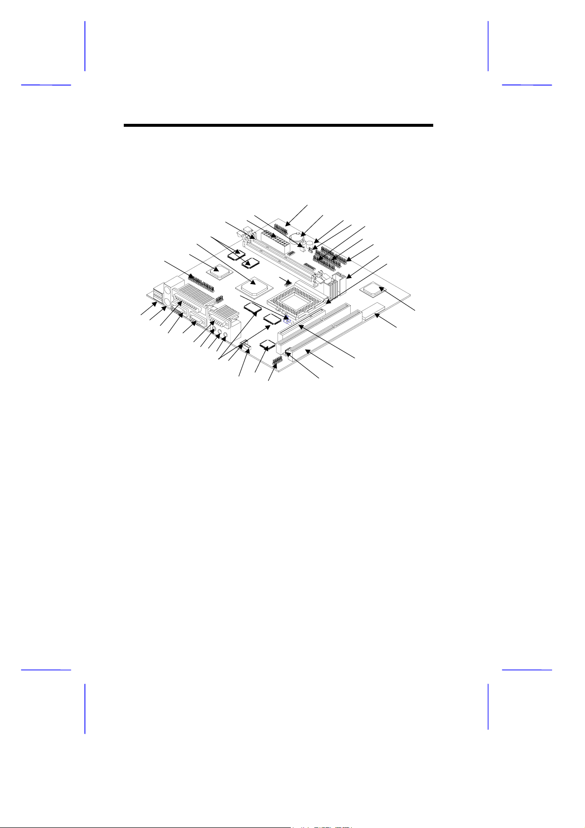
Figure 1 shows the locations of the maj or components on the system
board.
28
2
26
25 2
23 22
21
20
35
2
30
31
32
3
3
36
37
1
2
3
4 5
6
7 8 9
10 11
12 13
14
1 USB ports
2 PS/2 mouse/keyboard port
3 Parallel port
4 VGA port
5 COM2 port
6 Game/MIDI port
7 Line-out port
8 Line-in port
9 Microphone-in port
10 Second-level cache (pipeli ne-burst)
11 Fax/voice connector
12 CD-in connector
13 3-D audio controller
14 External CS4610 connector
15 Volume control connector
16 ISA slots
17 PCI slot
18 System BIOS chip
19 PCI-to-ISA bridge control l er
Figure 1 System Board Layout
19
18
1
16
1
20 CPU socket
21 Voltage controller with heatsink
22 IDE 1 connector
23 IDE 2 connector
24 FDD connector
25 Modem ring-in connector
26 Buzzer
27 Battery
28 Power button/ Reset / Turbo/ HDD/
Power, Suspend LED/IrDA connector
29 Wake-up On LAN connector
30 ATX power connector
31 DIMM sockets
32 Video memory
33 PCI, AGP, memory controller
34 3-D AGP video controller
35 ATI AMC feature connec t or
36 Tag RAM
37 CPU fan connector
4 User’s Guide
Page 17
3 Jumpers and Connectors
3.1 Jumper and Connector Locations
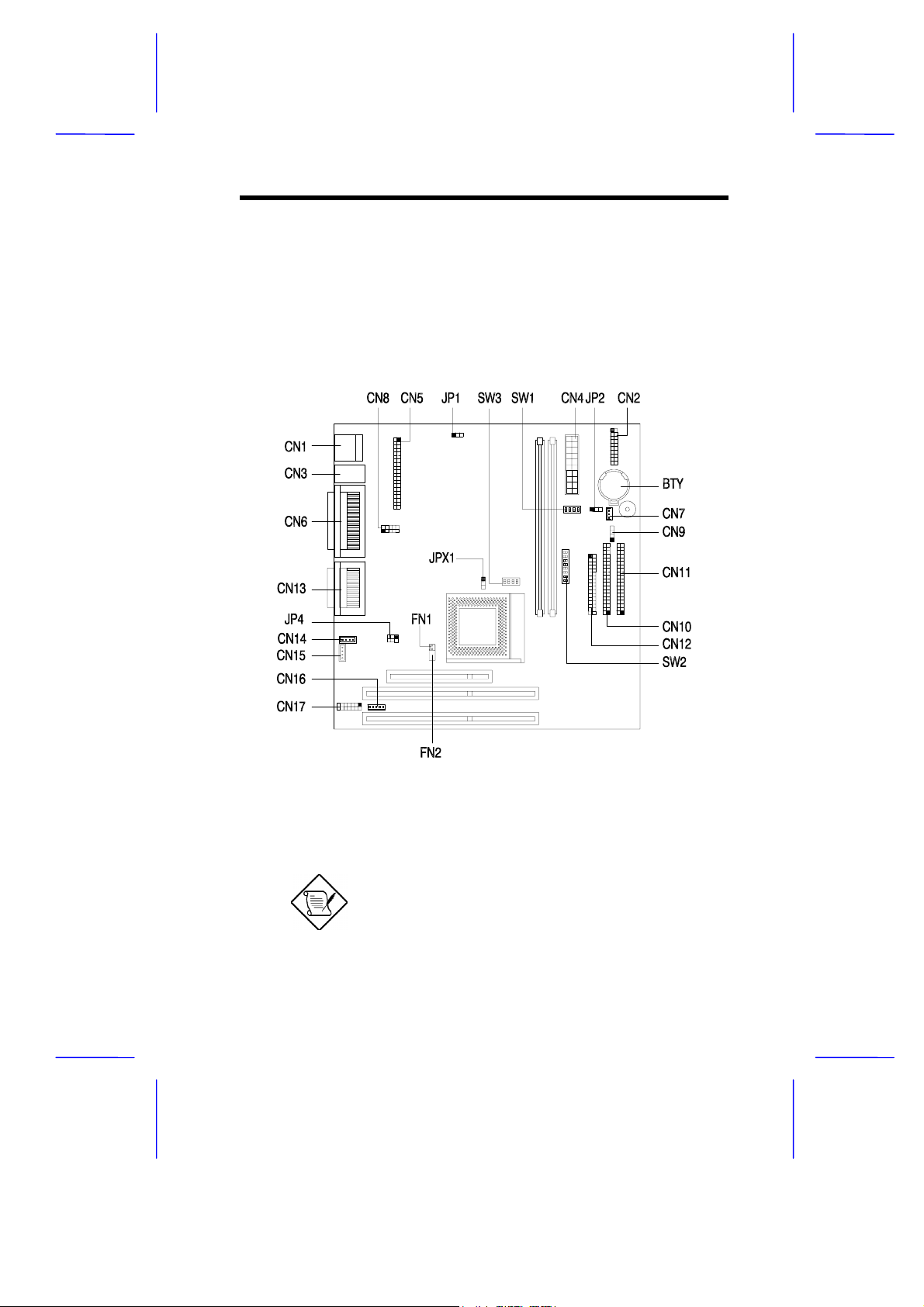
Figure 2 shows the jumper and connector locations on the system
board.
Figure 2 System Board Jumper and Connector Locations
The blackened pin of a jumper or a connector
represents pin 1.
V70MA System Board 5
Page 18
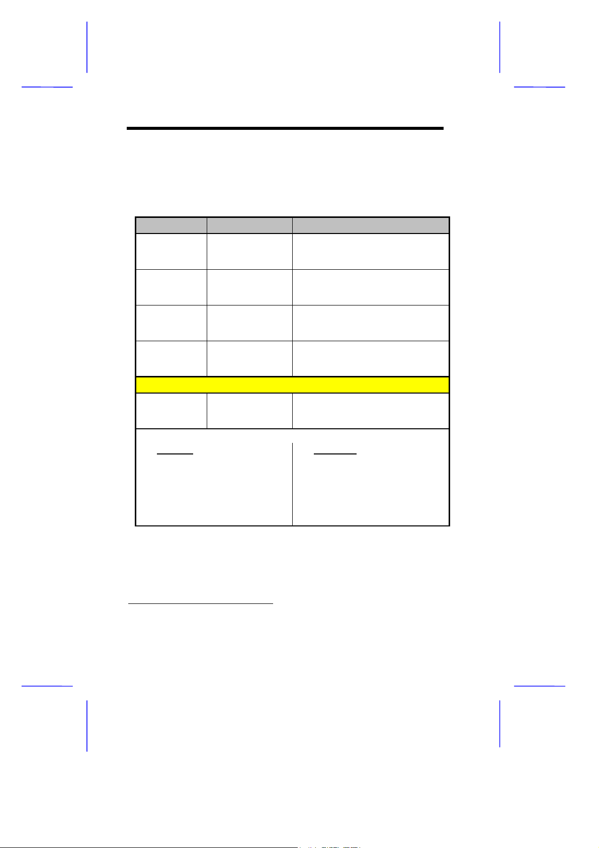
3.2 Jumper Settings
The following table lists the possible jumper settings:
Table 1 Jumper Settings
Jumper Setting Function
JP1 1-2
*
2-3
JP2 1-2
*
2-3
JP4 1-2, 4-5
2-3, 5-6
*
JPX1 1-2
*
2-3
SW1 Settings
B1 On
*
Off
Bus Frequency (MHz)
CY2283-1
B2 B3 B4 CPU AGP PCI
Clk. Clk. Clk.
Off On Off 66 66 33
Off Off Off 75 60 30
On On Off 83 66 33
*
On
Off *Off *100 66 33
VGA Interrupt
Disabled
Enabled
Wake-on LAN
Active low
Active high
Audio Line-in Source
AMC connector
Line-in connector
CPU Type
AMD K6S-300
Other CPUs
Hardware Monitor
Enabled
Disabled
ICS9148-16
B2 B3 B4 CPU AGP PCI
Off On On 66 66 33
On On Off 75 60 30
Off On Off 83 66 33
Off Off Off 100 66 33
Clk. Clk. Clk.
*
Default setting
6 User’s Guide
Page 19
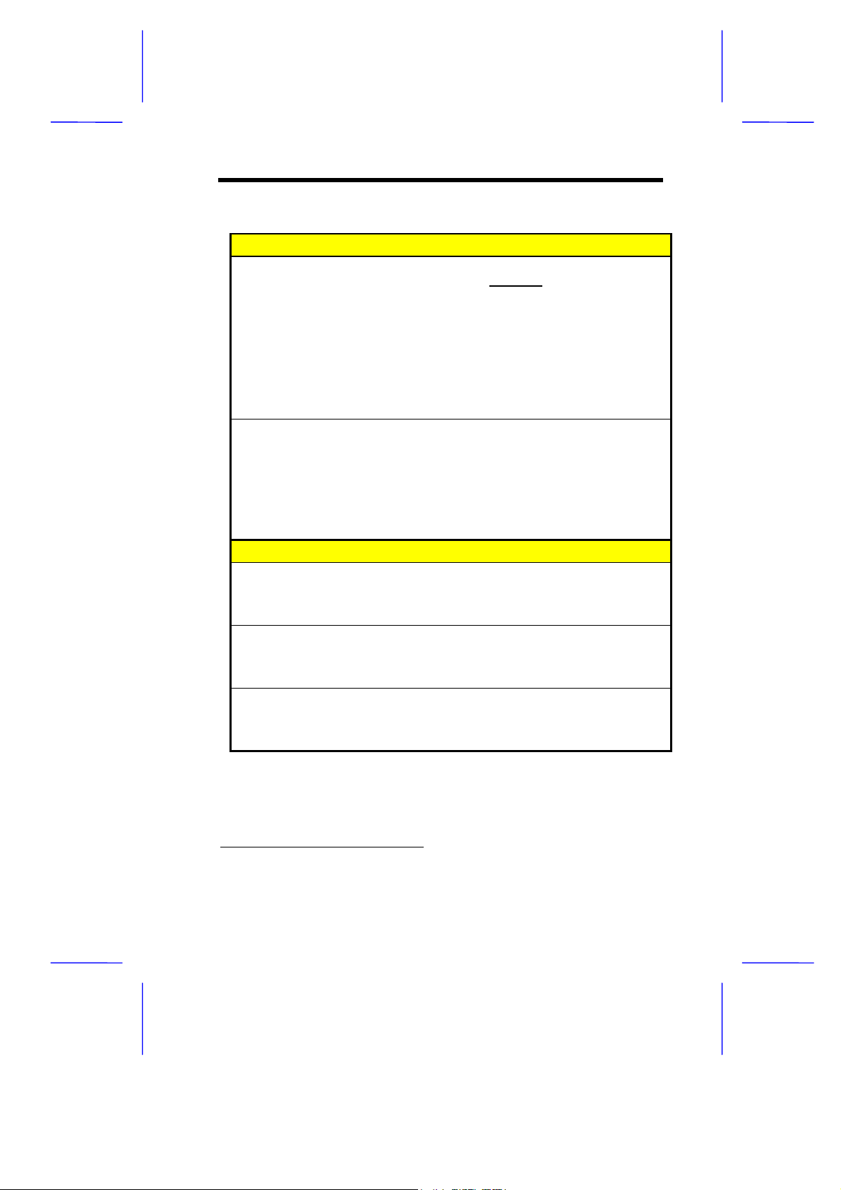
Table 1 Jumper Settings (continued)
SW2 Settings
CPU Core Clock Multi p lier
B1 B2 B3 K6 M2 P55C
Off Off Off 3.5 3.5 3.5
On Off On 4.0 2.0 2.0
*
Off
On *Off
*
On On Off 2.5 2.5 2.5
On On On 4.5 -- -On Off Off 2.0 -- -Off On On 5.0 -- -Off Off On 5.5 -- --
CPU Core Voltage
B4 B5 B6 B7 B8 Voltage
Off On On Off On 3.3
Off On On Off Off 3.2
Off On Off Off On 2.9
Off On Off Off Off 2.8
Off Off Off On On 2.3
Off
*
Off *Off
*
SW3 Settings
AMD K6S-300 Voltage Select
B1 Voltage
*
On
3.45V
Off 3.6V
Password Checking
B2 Function
On Check password
*
Off
Bypass password
M1542 Bus Frequency
B3 B4 Frequency
Off Off 66
On
*
On
*
CPU Type
3.0 *3.0 3.0
On *Off
*
100
2.2
*
*
Default setting
V70MA System Board 7
Page 20
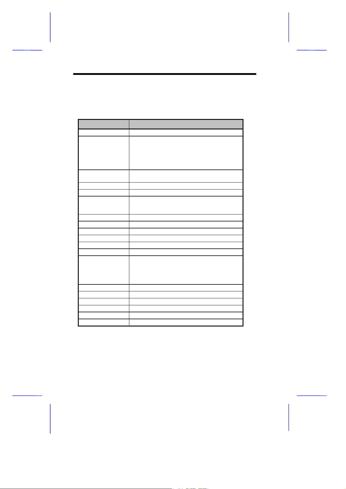
3.3 Onboard Connector Functions
Table 2 lists the onboard connectors and their respective functions.
Table 2 System Board Connectors
Connector Function
CN1 USB port
CN2 Power LED (pins 1-3)
CN3
CN4 ATX power connector
CN5 ATI AMC feature connector
CN6
CN7 Wake-on LAN connector
CN8 COM1 port
CN9 Modem ring-in connector
CN10 IDE2 connector
CN11 IDE1 connector
CN12 Floppy disk drive connector
CN13
CN14 Fax/voice connector
CN15 CD-in connector
CN16 Volume control connector
CN17 External CS4610 connector
FN1 2-pin CPU fan connect or
FN2 5-pin CPU fan connect or
HDD LED (pins 4-7)
Reset button (pins 8-9)
Power button (pins 10, 20)
IrDA connector (pins 14-19)
Turbo LED (pins 11-13)
PS/2 mouse port
Upper:
PS/2 keyboard port
Lower:
Parallel port
Upper:
VGA port (right)
Lower:
Upper:
Lower:
COM2 port (left)
Game/MIDI port
(R-to-L)
Microphone-in port
Stereo line-in port
Stereo line-out port
8 User’s Guide
Page 21

4 Installation Precautions
Before you install any system component, we recommend that you
read the following sections. These sections contain important ESD
precautions, pre- and post-installation instructions.
4.1 ESD Precautions
Electrostatic discharge (ESD) can damage your processor, disk drives,
expansion boards, and other components. Always observe the
following precautions before you install a system component:
1. Do not remove a component from its protective packaging until
you are ready to install it.
2. Wear a wrist grounding strap and attach it to a metal part of the
system unit before handling components . If a wrist strap is not
available, maintain contact with the system unit throughout any
procedure requiring ESD protection.
4.2 Pre-installation Instructions
Always observe the following before you install a system component:
1. Turn off the system power and all the peripherals connected to
the unit before opening it.
2. Open the system according to the instructions in the housing
installation manual.
3. Follow the ESD precautions in section 4.1 before handling a
system component.
4. Remove any expansion boards or peripherals that block access
to the DIMM sockets or CPU connector.
5. See the following sections for specific instructions on the
component you wish to install.
V70MA System Board 9
Page 22

Do not attempt the procedures described in
the following sections unless you are a
qualified service technician.
4.3 Post-installation Instructions
Observe the following after installing a system component:
1. See to it that the components are installed according to the stepby-step instructions in their respective sections.
2. Make sure you have set all the required jumpers. See s ect ion 3.2
for the correct jumper settings.
3. Replace any expansion boards or peripherals that you removed
earlier.
4. Replace the system cover.
5. Connect the necessary cables and turn on the system.
10 User’s Guide
Page 23
5 Memory Configurations
The system board comes with two 168-pin DIMM sockets that allow
you to expand memory to a maximum of 256 MB. The DIMM sock ets
support SDRAMs (Synchronous Direct Random Ac cess Memory) and
EDO (Extended Data Out) DRAMs with 8-, 16-, 32-, 64-, and 128-MB
capacities, 60 ns (nanoseconds) or less access tim e, and with ECC
feature.
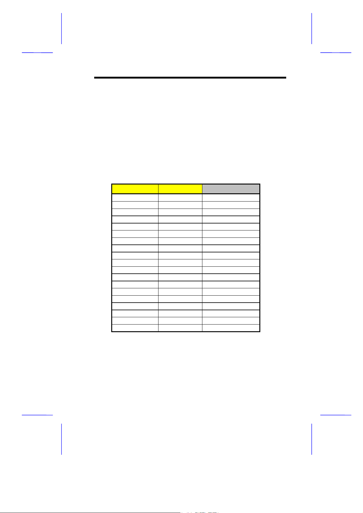
Table 3 lists possible memory configurations.
Table 3 Memory Configurations
DIMM1 DIMM2 Total Memory
8 MB 8 MB
16 MB 16 MB
32 MB 32 MB
64 MB 64 MB
128 MB 128 MB
8 MB 8 MB
16 MB 16 MB
32 MB 32 MB
64 MB 64 MB
128 MB 128 MB
8 MB 16 MB 24 MB
16 MB 32 MB 48 MB
32 MB 64 MB 96 MB
64 MB 128 MB 192 MB
8 MB 8 MB 16 MB
16 MB 16 MB 32 MB
32 MB 32 MB 64 MB
64 MB 64 MB 128 MB
128 MB 128 MB 256 MB
5.1 Installing a DIMM
Follow these steps to install a DIMM:
V70MA System Board 11
Page 24
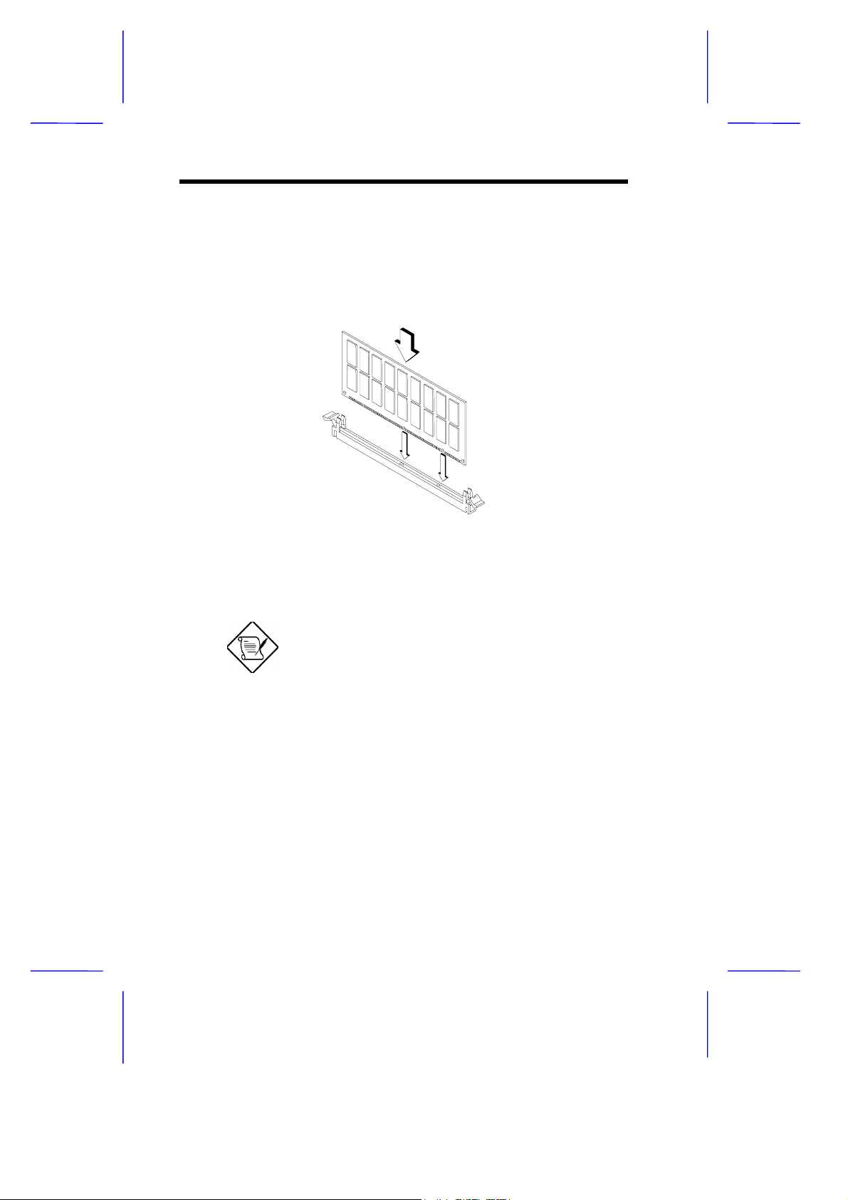
1. Open the clips on the socket.
2. Align the DIMM with the socket.
3. Press the DIMM into the socket until the clips lock into the DIMM.
Figure 3 Installing a DIMM
The DIMM socket is slotted to ensure pr oper
installation. If you insert a DIMM but it does
not fit easily into the socket, you may have
inserted it incorrectly. Turn the DIMM around
and try to insert it again.
5.2 Removing a DIMM
To remove a DIMM:
1. Press the holding clips on both sides of the socket outward to
release the DIMM.
12 User’s Guide
Page 25
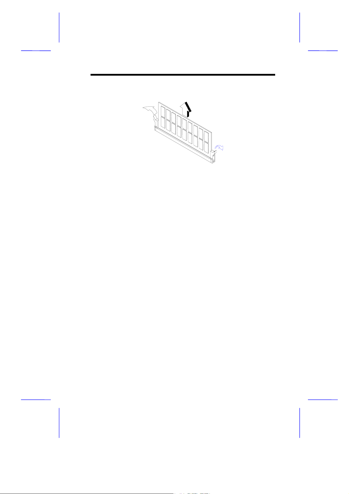
2. Gently pull the DIMM out of the socket.
Figure 4 Removing a DIMM
5.3 Reconfiguring the System
The system automatically detects the amount of memory installed.
Run Setup to view the new value for total system memor y and make a
note of it.
V70MA System Board 13
Page 26
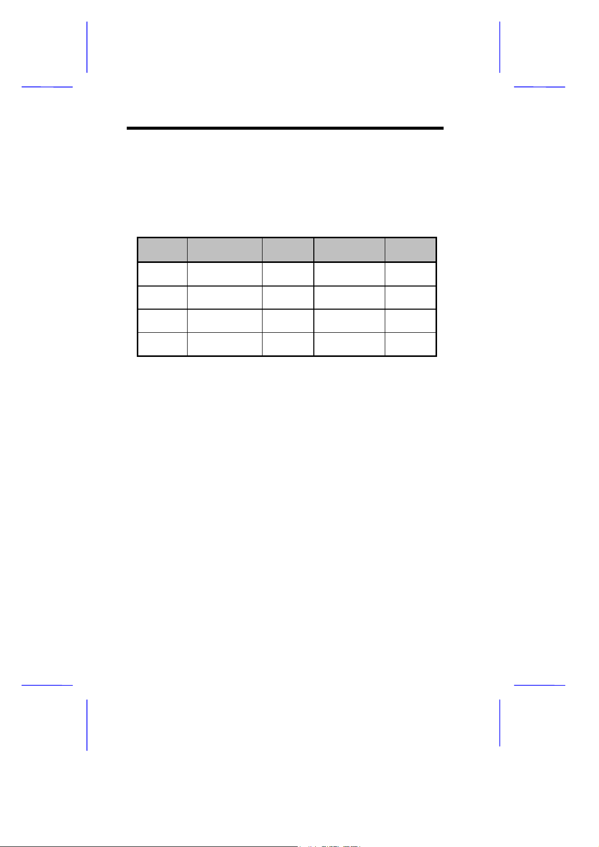
6 Second-level Cache
The board may come with either 256-KB or 512-KB pipelined-burst
second-level cache. Cacheless des ign is also s uppor ted. Ref er to the
following table for the possible cache configurations.
Table 4 Second-level Cache Configurations
Cache
Size
256 KB 32K x 32 x 2 pcs. U23, U26 32K x 8 x 1 pc
256 KB 32K x 32 x 2 pcs. U23, U26 16 x 10 x 1 pc
512 KB 64K x 32 x 2 pcs. U23, U26 32K x 8 x 1 pc
512 KB 64K x 32 x 2 pcs. U23, U26 16 x 10 x 1 pc
Data RAM
(12 ns)
Location Tag RAM
(12 ns) (U22)
(external)
(internal)
(external)
(internal)
Cacheabl
e Memory
256 MB
256 MB
128 MB
256 MB
7 Upgrading the CPU
7.1 Removing the CPU
In case you want to replace or upgrade your CPU, you need to remove
the previously installed CPU first.
Follow these steps to remove the CPU:
1. Locate the CPU socket with CPU mounted on the system board.
2. Detach the fan cable connector.
3. Pull up the socket lever. The CPU pins will be automatically
released from the socket holes.
4. Detach the CPU from the socket.
14 User’s Guide
Page 27
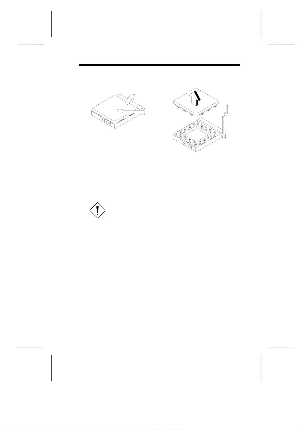
Figure 5 Removing the CPU
7.2 Installing the Upgrade CPU
Observe the ESD precautions when installing
components.
Before you proceed, make sure that there is no CPU ins talled in the
CPU socket.
Follow these steps to install the upgrade CPU:
1. Pull up the socket lever.
2. Insert the CPU, making sure that pin 1 (indicated by a notched
corner) of the CPU connects to hole 1 of the socket.
3. Pull down the socket lever to lock the CPU into the socket.
V70MA System Board 15
Page 28
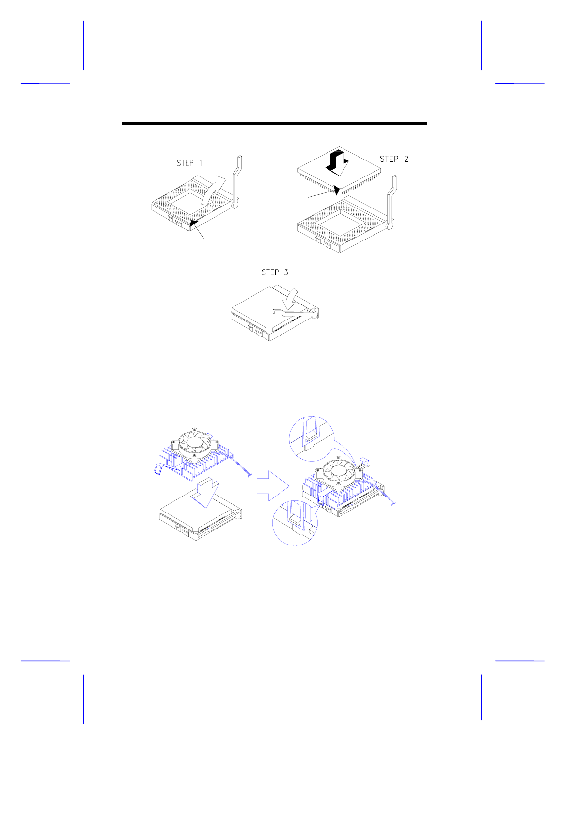
notched corner
hole 1
Figure 6 Installing a CPU
4. Attach the heatsink and fan to the CPU.
Figure 7 Attaching the Heatsink and Fan to the CPU
16 User’s Guide
Page 29
5. Plug the fan cable to the fan connector to its corresponding
connector on the system board. See Table 2 for the list of
onboard connectors and their functions.
8 IDE Hard Disk Sup port
The board comes with an enhanced PCI IDE controller that s upports
PIO mode 4 and Ultra DMA (Direct Memory Access) mode data
transfers. In addition, two PCI IDE interfaces are mounted on the riser
card to enable the system to support a maximum of four IDE hard
disks, or any other IDE devices. See Figure 2 for the location of the
IDE interfaces.
Connect the cables according to the IDE hard disk configuration in
Table 5. Follow the instructions in the housing installation m anual on
how to install a hard disk in the system.
Table 5 IDE Hard Disk Configuration
IDE Connector Master Slave
IDE 1 (CN11) Hard disk 0 Hard disk 1
IDE2 (CN10) Hard disk 2/ IDE
CD-ROM drive
Hard disk 3
V70MA System Board 17
Page 30
9 Video Function
The onboard video controller is capable not only of enhancing video
display, but supporting 3-D video applications as well. The video
controller features the Acceler ated Graphics Port (AGP) design - the
latest bus architecture that is considered to be the best solution for 3-D
applications. AGP offers greater bandwidth; thus, it is capable of
speeding up the VGA bus in order to meet the requirement of 3-D
applications.
The board may come with 2-MB upgradable to 4-MB video memory.
Larger video memory allows you to display higher resolutions and
more colors.
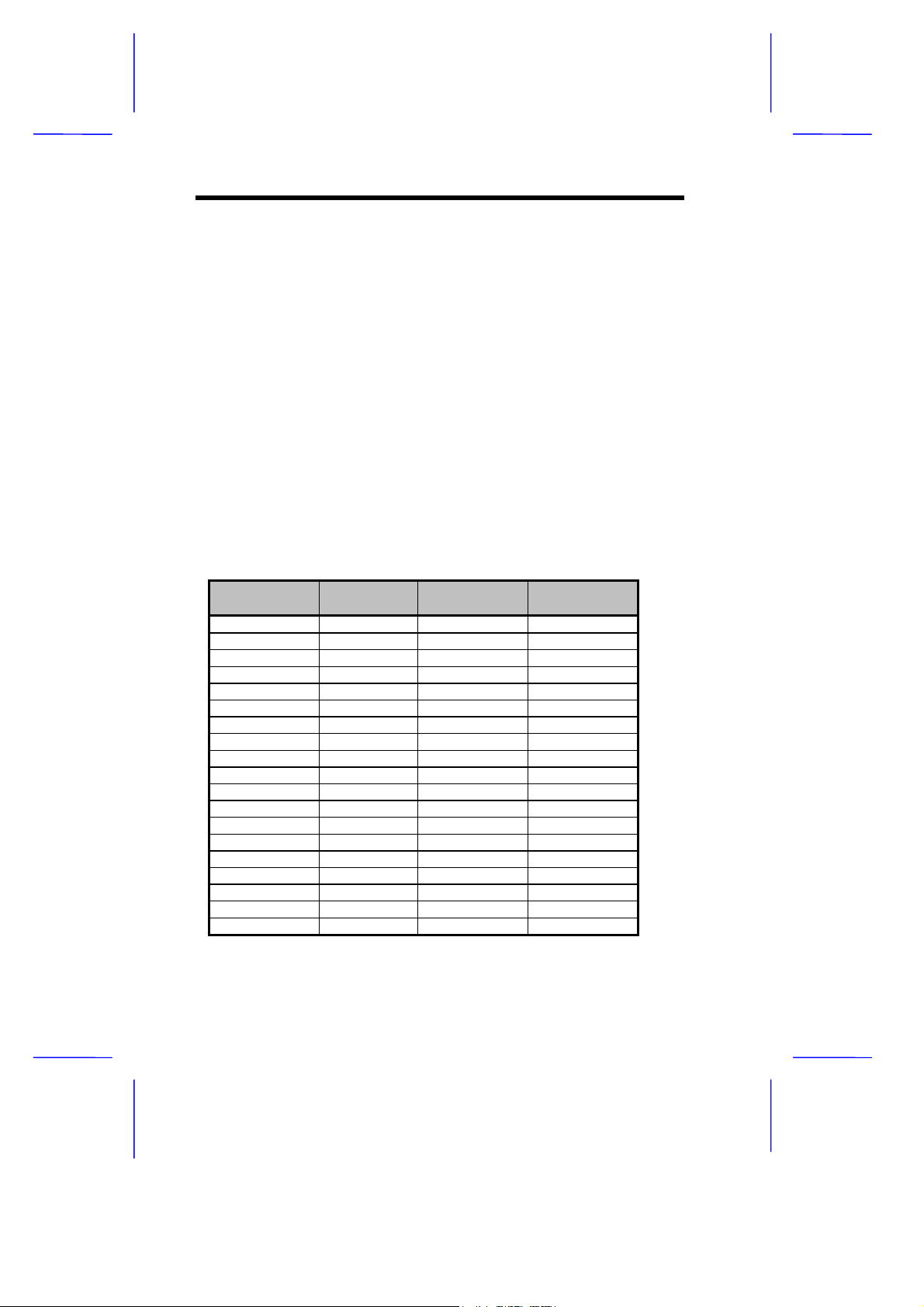
The following table lists the video resolutions supported by the
onboard VGA:
Table 6 Supported Video Resolutions
Resolution Refresh Rate
(Hz)
640 x 480 60 31.4 25.2
640 x 480 72 37.7 32.0
640 x 480 75 37.5 31.5
640 x 480 85 43.3 36.0
640 x 480 90 48.0 39.9
640 x 480 100 52.9 44.9
640 x 480 120 63.7 55.0
640 x 480 160 81.0 70.0
640 x 480 200 100.2 81.0
800 x 600 48 33.8 36.0
800 x 600 56 35.1 36.0
800 x 600 60 37.8 39.9
800 x 600 70 44.5 44.9
800 x 600 72 48.0 50.0
800 x 600 75 46.9 49.5
800 x 600 85 53.7 56.3
800 x 600 90 63.9 56.6
800 x 600 100 76.1 67.5
800 x 600 120 101.9 81.0
Horizontal
Freq. (KHz)
Pixel Clock
(MHz)
18 User’s Guide
Page 31
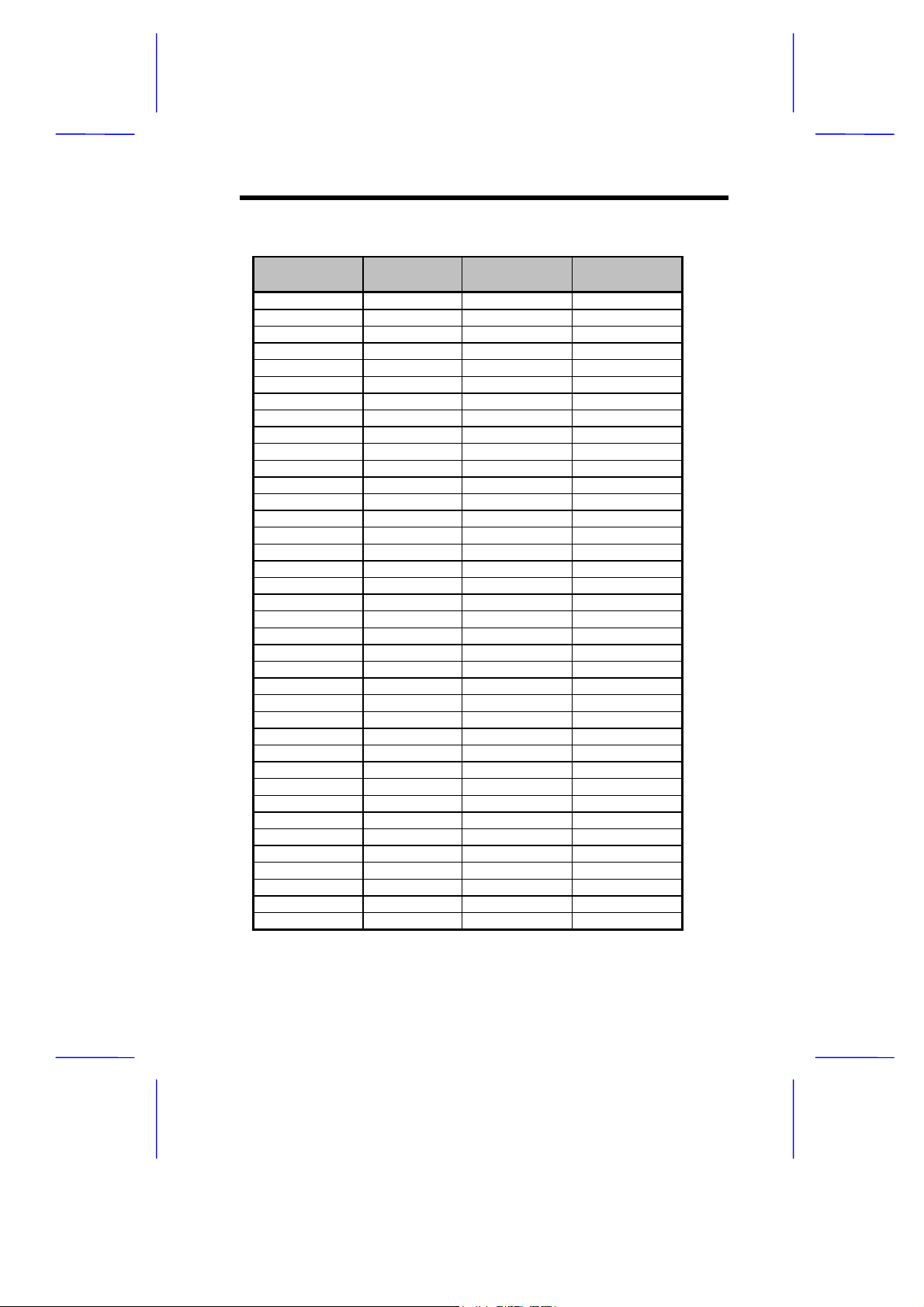
Table 6 Supported Video Resolutions
Resolution Refresh Rate
(Hz)
800 x 600 60 37.8 135.0
1024 x 768 43 35.5 44.9
1024 x 768 60 48.4 65.0
1024 x 768 70 56.1 75.0
1024 x 768 72 57.9 75.0
1024 x 768 75 60.0 78.8
1024 x 768 85 68.7 94.5
1024 x 768 90 76.2 100.0
1024 x 768 100 80.4 110.0
1024 x 768 120 96.7 130.0
1024 x 768 140 113.1 157.5
1024 x 768 150 120.6 160.0
1152 x 864 43 45.9 65.0
1152 x 864 47 44.9 65.0
1152 x 864 60 54.9 80.0
1152 x 864 70 66.1 100.0
1152 x 864 75 75.1 110.0
1152 x 864 80 76.4 110.0
1152 x 864 85 77.1 121.5
1152 x 864 100 90.2 135.0
1152 x 864 120 108.6 172.0
1280 x 1024 43 50.0 80.0
1280 x 1024 47 50.0 80.0
1280 x 1024 60 64.0 110.0
1280 x 1024 70 74.6 126.0
1280 x 1024 74 77.9 135.0
1280 x 1024 75 80.0 135.0
1280 x 1024 85 91.2 157.5
1280 x 1024 90 96.4 160.0
1280 x 1024 100 106.4 172.0
1600 x 1200 52 68.0 135.0
1600 x 1200 58 75.0 135.0
1600 x 1200 60 76.2 156.0
1600 x 1200 66 82.7 172.0
1600 x 1200 72 89.7 194.4
1600 x 1200 75 93.8 202.5
1600 x 1200 76 95.2 198.0
1600 x 1200 85 106.2 229.5
Horizontal
Freq. (KHz)
Pixel Clock
(MHz)
V70MA System Board 19
Page 32
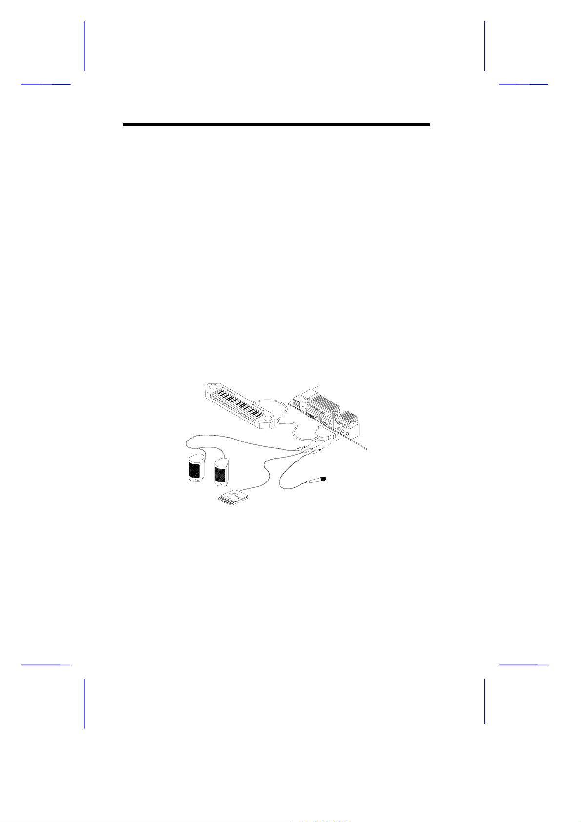
10 Audio Function
The board provides a com plete 3-D audio s olution via the onboar d 3- D
video controller and the following audio interfaces:
Microphone port
•
Line-in port
•
Line-out port
•
Game/MIDI port
•
CD-in connector
•
Voice Modem connector
•
These connectors enable the system to accommodate ex ternal audio
devices. To connect an audio device, simply plug in the device’s
connector to its corresponding onboard audio por t. See the following
figure:
MIDI device
speakers
microphone
CD player (or synthesizer)
Figure 8 Connecting External Audio Peripherals
Refer to Figure 1 or Figure 2 for the location of the audio connectors.
20 User’s Guide
Page 33
11 Expansion Cards
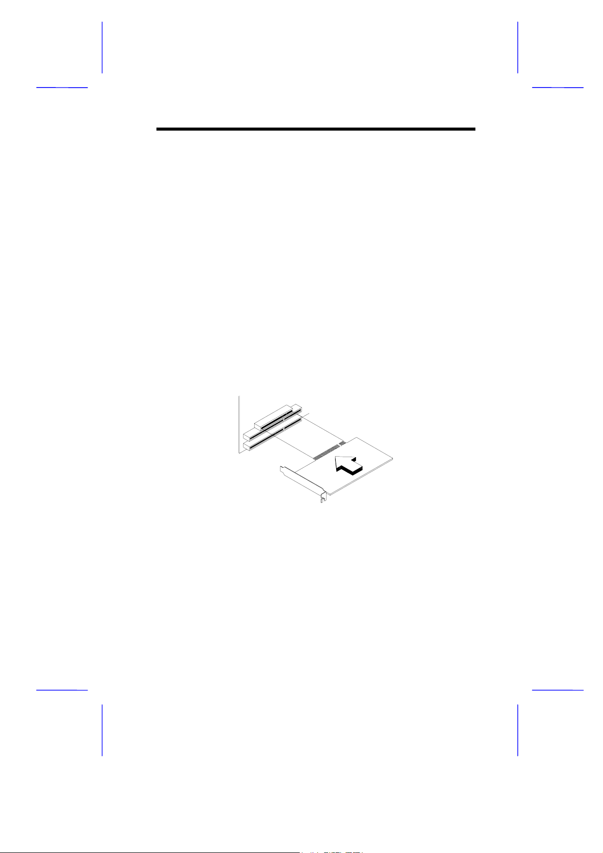
11.1 Installing a PCI Card
To install a PCI card:
1. Locate the PCI slot(s) on the system board.
2. Remove the bracket on the housing opposite to the empty PCI
slot.
3. Insert a PCI card into the slot. Make sure that the card is properly
seated.
4. Secure the card to the housing with a screw.
When you turn on the system, BIOS automatically detects and assigns
resources to the PCI devices.
Figure 9 Installing a PCI Card
V70MA System Board 21
Page 34

11.2 Installing ISA Cards
Both PnP and non-PnP ISA cards require specific IRQs (Interrupt
ReQuests). When installing ISA cards, make sure that the IRQs
required by these cards are not previously assigned to PCI devices to
avoid resource conflicts.
Follow these steps when installing ISA cards:
1. Turn off the system.
2. Open the system and remove all PnP cards installed in the
system, if any.
3. Install non-PnP ISA cards.
4. Turn on the system.
5. Use Windows 95 or ICU (ISA Configuration Utility) to manually
assign the appropriate IRQs to the cards. This ensures that BIOS
will not use the resources assigned to the non-PnP ISA cards.
BIOS detects and configures only PnP cards.
6. Turn off the system.
7. Locate the expansion slots and install the PnP ISA and PCI cards.
8. Turn on the system. This time PnP BIOS automatically
configures the PnP ISA and PCI cards with the available
resources.
22 User’s Guide
Page 35
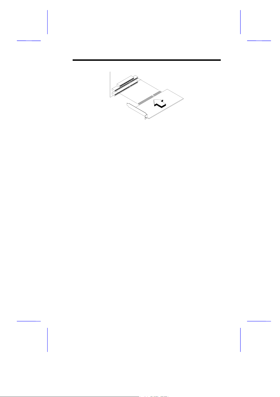
Figure 10 Installing an ISA Card
12 USB
USB (Universal Serial Bus) is a new serial bus design that is capable
of cascading low-/medium-speed peripherals (less than 12 Mbps)
such as a keyboard, mouse, joystick, scanner, printer and
modem/ISDN. With USB, complex cable connections at the back
panel of your PC can be eliminated.
The board comes with two USB ports (CN1) . See Figure 1 or Figur e 2
for the location of the ports.
V70MA System Board 23
Page 36

13 Wireless Communication Feature
The system supports Wireless Communication via an onboard infrared
interface (CN2 - see Figure 2). This feature enables the system to
communicate with SIR (Serial Inf raRed)-aware peripher als without the
aid of cables.
The onboard infrared interface is IrDA-compliant, allowing data
transfer at a rate of 115.2 k ilobits per second (Kbps) at a m aximum
distance of one meter.
14 Hardware Monitoring Function
The Hardware Monitoring function allows you to check the system
resources, either locally or in a computer network, by using software
such as Intel LDCM (LAN Desk Client Manager). ADM and Intel
LDCM are desktop management programs that offer the SMART
(System Monitoring Analysis and Reporting Technology) monitor
function for check ing local or network connec ted systems . In addition,
it also enables the PC products and applications to be OS (operating
system) independent.
To enable the Hardware Monitoring function, you need to install Intel
LDCM. Contact your dealer for information on the availability of the
software. Refer to the software docum entation f or m ore details on the
Hardware Monitoring function.
15 Wake-on Ring-in Function
The Wake-on Ring-in function enables the system to resume from
suspend mode by monitoring the fax/m odem (or any device of similar
type) activities. Any signal or activity detected from the Modem ring-in
connector automatically returns the system to normal operation. Refer
to Figure 2 for the location of the Modem ring-in connector (CN9) on
the system board.
24 User’s Guide
Page 37

16 Wake-on LAN Function
The system supports the Wake-on LAN feature via the onboard
Wake-on LAN connector (CN7). This special feature allows the
system to be activated on via a network. Comm on network functions,
such as remote access, file sharing, etc. are also supported.
17 Error Messages
In the event that you receive an error message, do not continue using
the computer. Note the message and take corrective action
immediately. This section describes the different types of error
messages and suggests corrective measures.
There are two general types of error messages:
Software
•
System
•
17.1 Software Error Messages
Software error messages are returned by your operating system or
application. These messages typically appear after you boot the
operating system or when you run your applications. If you receive
this type of message, consult your application or operating system
manual for help.
17.2 System Error Messages
A system error message indicates a pr oblem with the computer itself .
These messages normally appear during the power-on self-test,
before the operating system prompt appears. Table 7 lists the system
error messages.
V70MA System Board 25
Page 38
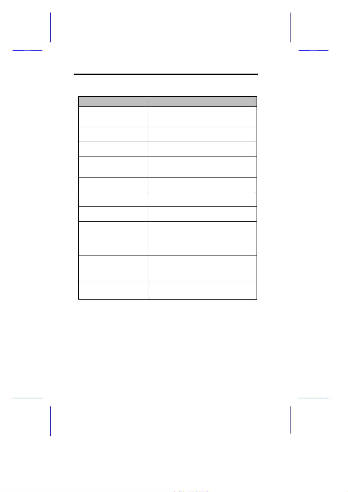
Table 7 System Error Messages
Error Message Corrective Action
Memory Error at
MMMM:SSSS:OOOOh
(R:xxxxh, W:xxxxh)
System Management
Memory Bad
Keyboard Interface Error Check the keyboard interface circuit or
Keyboard Error or
Keyboard Not
Connected
Pointing Device Error Reconnect or replace the pointing
Pointing Device Interface
Error
Pointing Device IRQ
Conflict
IDE Drive 0 Error
IDE Drive 1 Error
IDE Drive 2 Error
IDE Drive 3 Error
IDE Drive 0 (1, 2, 3) Auto
Detection Failed
Floppy Drive A Error
Floppy Drive B Error
Replace the DRAM chips or the DIMMs.
Replace the DRAM chips or the DIMMs.
change the keyboard.
Reconnect or replace the keyboard.
device.
Check the keyboard interface circuit.
Enter SETUP and change the setting of
IRQ12.
Replace the disk drive or the HDD (hard
disk drive) controller. Check the HDD
cable connections and CMOS setup
configuration.
Replace the disk drive or the hard disk
drive controller. Check the HDD cable
connections and CMOS setup
configuration.
Replace the floppy drive.
26 User’s Guide
Page 39
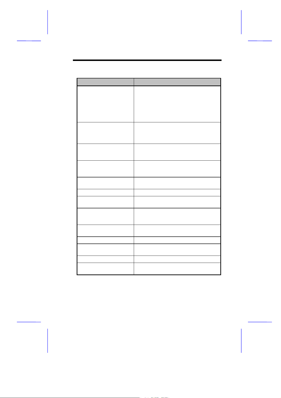
Table 7 System Error Messages (continued)
Error Message Corrective Action
Floppy Disk Controller
Error
CPU Clock Mismatch When the user changes the CPU
Serial Port 1 Conflict
Serial Port 2 Conflict
Parallel Port Conflict Change the onboard parallel port
Real Time Clock Error Check the RTC circuit or replace the
CMOS Battery Bad Replace the onboard lithium battery.
CMOS Checksum Error Run Setup again and reconfigure the
NVRAM checksum Error Run the ECU (Extended ISA
On Board xxx ...
Conflict(s)
PCI Device Error Check the PCI card. Replace it if bad.
System Resource
Conflict
IRQ Setting Error Run Setup to reconfigure the system.
Expansion ROM
Allocation Fail
Check the floppy drive cable and its
connections. If the cable is good and
properly connected, the floppy disk
controller may be the problem. Change
the floppy disk controller or disable the
onboard controller by installing another
add-on card with a controller.
frequency, this message will be shown
once. Then the BIOS will adjust the
CPU clock automatically.
Change the onboard serial port address
in Setup or change the add-on card
serial port address.
address in CMOS Setup or the parallel
port address of the add-on card.
RTC.
system.
Configuration Utility) to restore the
original EISA configuration data.
Try to reassign or disable onboard
device resources.
Run Setup to reconfigure the system.
Change the I/O expansion ROM
address.
V70MA System Board 27
Page 40

17.3 Correcting Error Conditions
As a general rule, the "Press F1 to continue" error m essage is caus ed
by a configuration problem which can be easily corrected. An
equipment malfunction is more likely to cause a fatal error, i.e., an
error that causes complete system failure.
Here are some corrective measures for error conditions:
1. Run Setup. You must know the correct configuration values for
your system before you enter Setup, which is why you should
write these values down when the system is correctly configured.
An incorrect Setup configuration is a major cause of power-on
error messages, especially for a new system.
2. Remove the system cover according to the directions in the
system housing installation guide. Check that the system board
and any expansion boards are set correctly.
3. Check that all connectors and boards are secure. Consult the
system housing installation guide for assistance.
If you have purchased a new hard disk drive
and cannot access it, it may be because your
disk is not physically formatted. Physically
format the disk using the FDISK and
FORMAT commands.
If you follow the corrective steps above and still receive an error
message, the cause may be an equipment malfunction.
If you are sure that your configuration values are correct and your
battery is in good condition, the problem may lie in a damaged or
defective chip. Contact an authorized service center for assistance.
28 User’s Guide
 Loading...