

Page 1

V62X System
User’s Guide
Page 2

Copyright
Copyright ã 1997 by this company. All rights reserved. No part of
this publication may be reproduced, transmitted, transcribed, stored in
a retrieval system, or translated into any language or computer
language, in any form or by any means, electronic, mechanical,
magnetic, optical, chemical, manual or otherwise, without the prior
written permission of this company.
Disclaimer
This company makes no representations or warranties, either
expressed or implied, with respect to the contents hereof and
specifically disclaims any warranties, merchantability or fitness for any
particular purpose. Any software described in this manual is sold or
licensed "as is". Should the programs prove defective following their
purchase, the buyer (and not this company, its distributor, or its dealer)
assumes the entire cost of all necessary servicing, repair, and any
incidental or consequential damages resulting from any defect in the
software. Further, this company reserves the right to revise this
publication and to make changes from time to time in the contents
hereof without obligation to notify any person of such revision or
changes.
Intel is a registered trademark of Intel Corporation.
Pentium is a trademark of Intel Corporation.
ii
Page 3

Other brand and product names are trademarks and/or registered trademarks of their
respective holders.
iii
Page 4

IMPORTANT SAFETY
INSTRUCTIONS
1. Read these instructions carefully. Save these instructions for
future reference.
2. Follow all warnings and instructions marked on the product.
3. Unplug this product from the wall outlet before cleaning. Do not
use liquid cleaners or aerosol cleaners. Use a damp cloth for
cleaning.
4. Do not use this product near water.
5. Do not place this product on an unstable cart, stand, or table.
The product may fall, causing serious damage to the product.
6. Slots and openings in the cabinet and the back or bottom are
provided for ventilation; to ensure reliable operation of the product
and to protect it from overheating, these openings must not be
blocked or covered. The openings should never be blocked by
placing the product on a bed, sofa, rug, or other similar surface.
This product should never be placed near or over a radiator or
heat register, or in a built-in installation unless proper ventilation is
provided.
7. This product should be operated from the type of power indicated
on the marking label. If you are not sure of the type of power
available, consult your dealer or local power company.
8. This product is equipped with a 3-wire grounding-type plug, a plug
having a third (grounding) pin. This plug will only fit into a
grounding-type power outlet. This is a safety feature. If you are
unable to insert the plug into the outlet, contact your electrician to
replace your obsolete outlet. Do not defeat the purpose of the
grounding-type plug.
iv
Page 5

9. Do not allow anything to rest on the power cord. Do not locate
this product where persons will walk on the cord.
10. If an extension cord is used with this product, make sure that the
total ampere rating of the equipment plugged into the extension
cord does not exceed the extension cord ampere rating. Also,
make sure that the total rating of all products plugged into the wall
outlet does not exceed 15 amperes.
11. Never push objects of any kind into this product through cabinet
slots as they may touch dangerous voltage points or short out
parts that could result in a fire or electric shock. Never spill liquid
of any kind on the product.
12. Do not attempt to service this product yourself, as opening or
removing covers may expose you to dangerous voltage points or
other risks. Refer all servicing to qualified service personnel.
13. Unplug this product from the wall outlet and refer servicing to
qualified service personnel under the following conditions:
a. When the power cord or plug is damaged or frayed
b. If liquid has been spilled into the product
c. If the product has been exposed to rain or water
d. If the product does not operate normally when the operating
instructions are followed. Adjust only those controls that are
covered by the operating instructions since improper
adjustment of other controls may result in damage and will
often require extensive work by a qualified technician to
restore the product to normal condition.
e. If the product has been dropped or the cabinet has been
damaged
f. If the product exhibits a distinct change in performance,
indicating a need for service
v
Page 6

14. Replace battery with the same type as the product's battery we
recommend. Use of another battery may present a risk of fire or
explosion. Refer battery replacement to a qualified serviceman.
15. Warning! Battery may explode if not handled properly. Do not
recharge, disassemble or dispose of in fire. Keep away from
children and dispose of used battery promptly.
16. Use only the proper type of power supply cord set (provided in
your keyboard/manual accessories box) for this unit. It should be
a detachable type: UL listed/CSA certified, type SVT/SJT, rated
6A 125V minimum, VDE approved or its equivalent. Maximum
length is 15 feet (4.6 meters).
vi
Page 7

FCC Class B Radio Frequency Interference
Statement
Note:
This equipment has been tested and found to comply with the limits for
a Class B digital device, pursuant to Part 15 of FCC Rules. These
limits are designed to provide reasonable protection against harmful
interference in a residential installation. This equipment generates,
uses, and can radiate radio frequency energy and, if not installed and
used in accordance with the instructions, may cause harmful
interference to radio communications. However, there is no guarantee
that interference will not occur in a particular installation. If this
equipment does cause harmful interference to radio or television
reception, which can be determined by turning the equipment off and
on, the user is encouraged to try to correct the interference by one or
more of the following measures:
1. Reorient or relocate the receiving antenna.
2. Increase the separation between the equipment and receiver.
3. Connect the equipment into an outlet on a circuit different from
that to which the receiver is connected.
4. Consult the dealer or an experienced radio/television technician
for help.
Notice 1:
The changes or modifications not expressly approved by the party
responsible for compliance could void the user's authority to operate
the equipment.
Notice 2:
Shielded interface cables, if any, must be used in order to comply with
the emission limits.
vii
Page 8

About this Manual
Purpose
This user’s guide aims to give you all the necessary information to
enable you to operate the system properly.
Manual Structure
This user’s guide consists of two chapters.
Chapter 1 System Board
This chapter describes the system board and all its major
components. It contains the system board layout, jumper
settings, cache and memory configurations, and information on
other internal devices.
Chapter 2 BIOS Utility
This chapter gives information about the system BIOS and tells
how to configure the system by changing the settings of the
BIOS parameters.
viii
Page 9
Conventions
The following are the conventions used in this manual:
Text entered by user Represents text input by the user.
Screen messages
Denotes actual messages that
appear on the screen.
a, e, s, etc. Represent the actual keys that you
have to press on the keyboard.
NOTE
Gives bits and pieces of additional
information related to the current
topic.
WARNING
Alerts you to any damage that
might result from doing or not doing
specific actions.
CAUTION
Gives precautionary measures to
avoid possible hardware or
software problems.
IMPORTANT
Reminds you to do specific actions
relevant to the accomplishment of
procedures.
TIP
Tells how to accomplish a
procedure with minimum steps
through little shortcuts.
ix
Page 10

Table of Contents
Chapter 1 System Board
1.1 Major Features........................................................... 1-2
1.2 Board Layout..............................................................1-3
1.3 Jumpers and Connectors...........................................1-4
1.3.1 Jumper and Connector Locations...............1-4
1.3.2 Jumper Settings..........................................1-5
1.3.3 Connector Functions...................................1-7
1.4 ESD Precautions........................................................1-8
1.5 Pre-installation Instructions........................................1-8
1.6 Pentium II Processor..................................................1-9
1.6.1 Installing a Pentium II Processor...............1-10
1.6.2 Removing a Pentium II Processor.............1-12
1.7 Memory Configurations............................................1-13
1.7.1 Rules for Adding Memory..........................1-13
1.7.2 Installing a SIMM.......................................1-16
1.7.3 Removing a SIMM.....................................1-17
1.7.4 Reconfiguring the System.........................1-18
1.8 IDE Hard Disk Support.............................................1-18
1.9 Add-on Card Installation...........................................1-19
1.9.1 Installing ISA Cards...................................1-19
1.9.2 Installing a PCI Card.................................1-20
1.9.3 Installing a SCSI/LAN Card.......................1-21
1.10 Post-installation Instructions....................................1-23
1.11 USB.........................................................................1-23
x
Page 11

1.12 Hardware Monitor Function......................................1-23
1.13 Error Messages........................................................1-24
1.13.1 Software Error Messages..........................1-24
1.13.2 System Error Messages............................1-24
1.13.3 Correcting Error Conditions.......................1-27
Chapter 2 BIOS Utility
2.1 Entering Setup...........................................................2-2
2.2 Basic System Configuration.......................................2-3
2.2.1 Date and Time.............................................2-4
2.2.2 Diskette Drives............................................2-5
2.2.3 IDE Drives...................................................2-5
2.2.4 Total Memory..............................................2-7
2.2.5 Enhanced IDE Features..............................2-8
2.2.6 Num Lock After Boot...................................2-9
2.2.7 Memory Test...............................................2-9
2.2.8 Quiet Boot...................................................2-9
2.2.9 Configuration Table...................................2-10
2.3 Advanced System Configuration..............................2-11
2.3.1 L1 Cache (CPU Cache)............................2-11
2.3.2 L2 Cache...................................................2-12
2.3.3 ECC/Parity Mode Selection.......................2-12
2.3.4 Memory at 15MB-16MB Reserved For......2-12
2.4 PCI System Configuration........................................2-13
2.4.1 PCI IRQ Setting.........................................2-13
2.4.2 PCI IRQ Sharing.......................................2-14
2.4.3 VGA Palette Snoop...................................2-14
xi
Page 12

2.4.4 Plug & Play OS.........................................2-15
2.4.5 Reset Resources Assignment...................2-15
2.5 Power Saving Configuration.....................................2-16
2.5.1 Power Management Mode........................2-16
2.5.2 Monitored Activities...................................2-17
2.6 System Security Setup.............................................2-18
2.6.1 Disk Drive Control.....................................2-18
2.6.2 Onboard Communication Ports.................2-20
2.6.3 Onboard PS/2 Mouse (IRQ 12).................2-23
2.6.4 Setup Password........................................2-23
2.6.5 Power On Password.................................2-26
2.7 Load Setup Default Settings.....................................2-26
2.8 Leaving Setup..........................................................2-27
List of Figures
1-1 System Board Layout.................................................1-3
1-2 System Board Jumper and Connector Locations.......1-4
1-3 Installing the Retention Mechanism..........................1-10
1-4 Installing a Pentium II Processor..............................1-11
1-5 Removing a Pentium II Processor............................1-12
1-6 Installing a SIMM......................................................1-16
1-7 Removing a SIMM....................................................1-17
1-8 Installing an ISA Card...............................................1-20
1-9 Installing a PCI Card................................................1-21
1-10 Installing a SCSI/LAN Card......................................1-22
List of Tables
1-1 Jumper Settings.........................................................1-5
xii
Page 13

1-2 Onboard Connectors..................................................1-7
1-3 Memory Configurations............................................1-14
1-4 IDE Hard Disk Configuration....................................1-18
1-5 System Error Messages...........................................1-25
2-1 Drive Control Settings..............................................2-19
2-2 Serial Port 1 Settings................................................2-20
2-3 Serial Port 2 Settings................................................2-21
2-4 Parallel Port Settings................................................2-21
2-5 Parallel Port Operation Mode Settings.....................2-22
xiii
Page 14

C h a p t e r
1
System Board
The V62X is a high-performance system board that utilizes the new
Intel Pentium II processor. This processor has a built-in MMX
(Multi-Media Extensions) technology that makes the system capable of
handling and enhancing the performance of 32-bit applications and
multimedia functions.
The system board supports PnP (Plug-and-Play) and power
management functions. In addition, it also offers the hardware monitor
function. This DMI (Desktop Management Interface) feature enables
you to monitor the system resources of your PC or of systems in a
network.
For expansion, the system board integrates in its design three ISA and
four PCI slots. It also has a SCSI (Small Computer System Interface) /
LAN (Local Area Network) interface to support SCSI devices and
network functions. The six SIMM (Single In-line Memory Module)
sockets on board allow you to upgrade the system memory to a
maximum of 384 MB.
Notice that the board does not come with an external second-level
cache. This is because the second-level cache is already integrated in
the Pentium II CPU card. The CPU card may come with 256-KB or
512-KB second-level cache size.
The board comes with standard I/O interfaces such as two UART
16C550 serial ports, a parallel port with SPP (Standard Parallel
Port)/ECP (Extended Capabilities Port)/EPP (Enhanced Parallel Port)
feature, PS/2 keyboard and mouse ports. The board also includes a
USB (Universal Serial Bus) interface to enable the system to support
additional peripherals.
System Board 1-1
Page 15

1.1 Major Features
The system board has the following major features and components:
· Supports Intel Pentium II processor running at 233 or 266 MHz
· 256/512-KB PBSRAM (Pipelined-burst SRAM) second-level cache
(incorporated in the CPU card)
· Six SIMM sockets that accepts FPM (Fast Page Mode) and EDO
(Extended Data Out) RAMs for memory upgrade
· Onboard PCI local bus IDE controller
· Onboard 256K Flash BIOS ROM
· Three ISA and four PCI slots for future expansion
· SCSI and Ethernet combo card interface
· Two PCI enhanced IDE interfaces that support up to four IDE
devices
· External ports:
· PS/2 keyboard and mouse ports
· Two buffered high-speed serial ports
· One SPP/ECP/EPP high-speed parallel port
· Two USB ports
· Power management features
· APM v1.2 (Advanced Power Management)-compliant BIOS
· API (Application Program Interface) feature
· ATA (Advanced Technology Attachment)-compliant hard disk
power saving feature
· PnP (Plug-and-Play) feature
· Windows 95 software shutdown support
· ADM (Advanced Desktop Manager) hardware monitor function
1-2 User’s Guide
Page 16
· ATX form factor
1.2 Board Layout
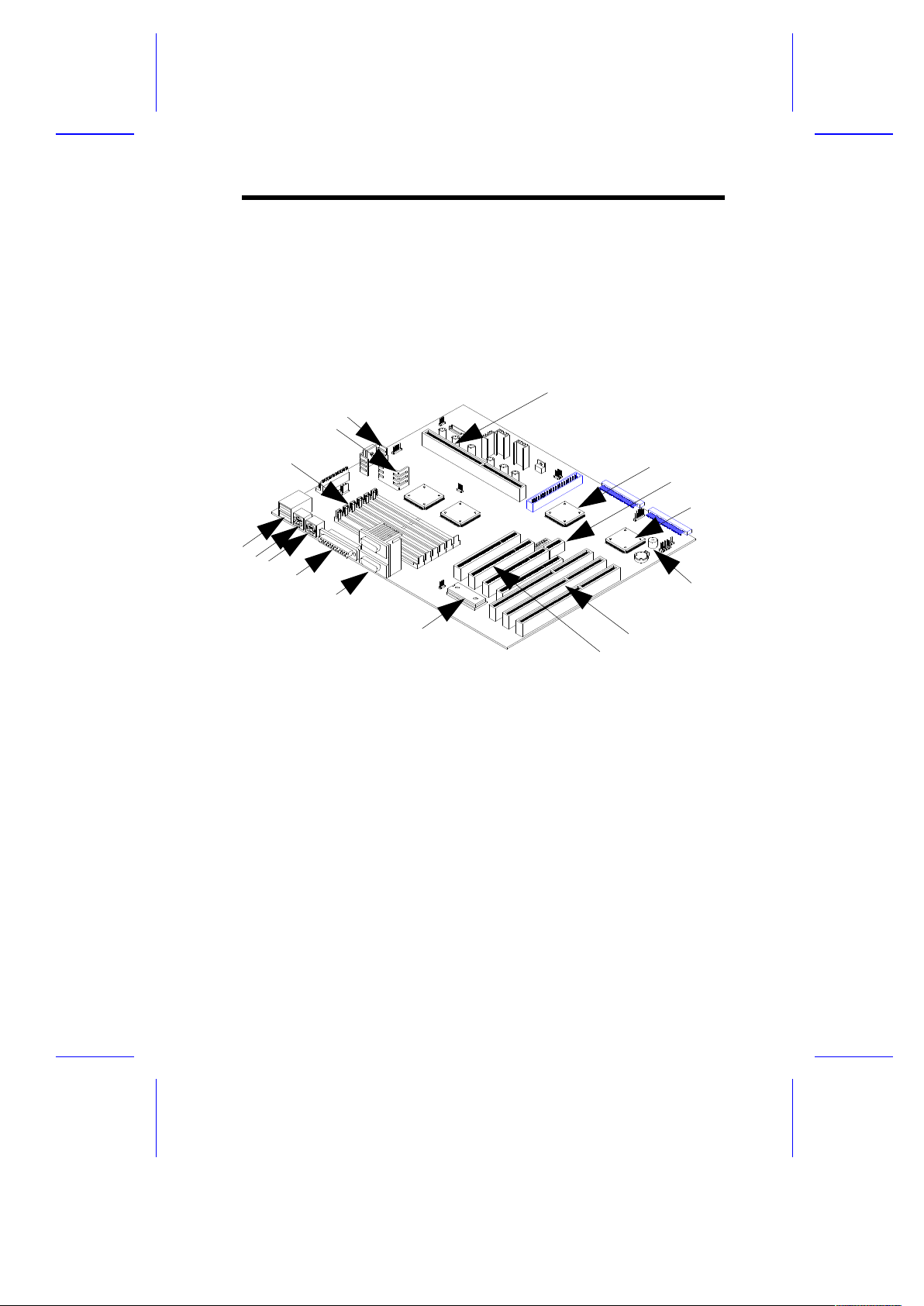
Figure 1-1 shows the locations of the system board major
components.
1 72-pin SIMM sockets
2 3.3V regulator
3 1.5V regulator
4 Pentium II connector
5 PCI local bus IDE controller
6 SCSI/LAN card slot
7 Ultra I/O controller
8 Buzzer
9 ISA slots
10 PCI slots
11 Flash BIOS ROM
12 COM1/2 ports
13 Printer port
14 PS/2 mouse port
15 PS/2 keyboard port
16 USB ports
Figure 1-1 System Board Layout
System Board 1-3
1
4
5
6
7
8
9
1
0
1
1
1
2
1
3
1
4
1
6
1
5
2
3
Page 17
1.3 Jumpers and Connectors
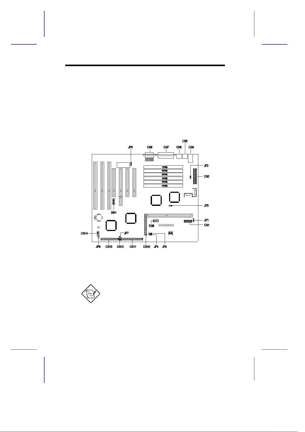
1.3.1 Jumper and Connector Locations
Figure 1-2 shows the jumper and connector locations on the system
board.
Figure 1-2 System Board Jumper and Connector Locations
The blackened pin of a jumper or a connector
represents pin 1.
1-4 User’s Guide
Page 18
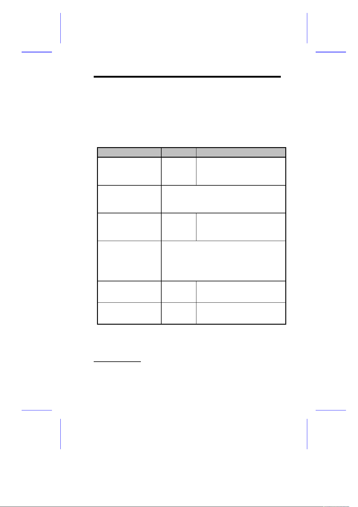
1.3.2 Jumper Settings
Table 1-1 lists the system board jumpers with their corresponding
settings and functions.
Table 1-1 Jumper Settings
Jumper Setting Function
Power On Setting
(only for S/W power supply)
JP1
1-2
2-3 *
Test mode
Normal mode
CPU select
JP3, JP4, JP5
Jumpers
JP3 JP4 JP5 CPU
1-2 1-2 1-3, 2-4 Pentium Pro
2-3 * 2-3 * 3-5, 4-6 * Pentium II
ROM Select
JP6 1-2
2-3
Open *
EPROM
Flash EEROM & 28F001
29EE010/020
Frequency Select
SW1
Switch No.
1 2 Host Clock PCI Clock
On On Reserved Reserved
Off On 60 MHz 30 MHz
On * Off * 66 MHz 33 MHz
Off Off XIN/2 XIN/4
Password Check
SW1 (Switch No. 3) On *
Off
Bypass password
Check password
BIOS Logo
SW1 (Switch No. 4) On
Off *
OEM BIOS
Acer BIOS
*
Default setting
System Board 1-5
Page 19

Table 1-1 Jumper Settings (continued)
Jumper Setting Function
Core/Bus Ratio
SW1
Switch No.
5 6 7 8 Core/Bus Ratio
On On On On 2
On On Off On 3
On * On * On * Off * 4
On On Off Off 5
On Off On On 2.5
On Off Off On 3.5
On Off On Off 4.5
On Off Off Off 5.5
Off On On On 6
Off On Off On 7
Off On On Off 8
Off Off On On 6.5
Off Off Off On 7.5
Off Off On Off 1.5
Off Off Off Off 2
Off On Off Off Reserved
1-6 User’s Guide
Page 20

1.3.3 Connector Functions
Table 1-2 lists the different connectors on the system board and their
respective functions.
Table 1-2 Onboard Connectors
Connector Function
CN1 Power connector
CN3 USB port(s)
CN4 PS/2 keyboard port
CN5 In-Target Probe (ITP) debug port
CN6 PS/2 mouse port
CN7 Parallel/printer port
CN9 COM1/2 port(s)
CN10 HDD channel 2 connector
CN11 HDD channel 1 connector
CN12 InfraRed (IrDA) connector
CN13 FDD connector
CN14 Multifunction connector
Pin No. Function
2-6 Power LED
7-8 Reset
1-3 Speaker
JP2 Standby power cable connector
JP8 Software power control connector
JP7 HDD LED connector
System Board 1-7
Page 21

1.4 ESD Precautions
Always observe the following electrostatic discharge (ESD)
precautions before installing a system component:
1. Do not remove a component from its anti-static packaging until
you are ready to install it.
2. Wear a wrist grounding strap before handling electronic
components. Wrist grounding straps are available at most
electronic component stores.
Do not attempt the procedures described in
the following sections unless you are a
qualified technician.
1.5 Pre-installation Instructions
Always observe the following before you install a system component:
1. Turn off the system power and all the peripherals connected to
the unit before opening it.
2. Open the system according to the instructions in the housing
installation manual.
3. Follow the ESD precautions in section 1.4 before handling a
system component.
4. Remove any expansion boards or peripherals that block access
to the SIMM sockets or CPU socket.
5. See the following sections for specific instructions on the
component you wish to install.
1-8 User’s Guide
Page 22

Do not attempt the procedures described in
the following sections unless you are a
qualified service technician.
1.6 Pentium II Processor
The board supports the Pentium II processor - a module that consists
of a Pentium Pro technology-based CPU and a second-level cache. It
utilizes the new enclosed packaging technology called S.E.C (singleedge contact) cartridge, that allows the second-level cache to remain
tightly coupled to the processor. It is capable of increasing the
performance of 32-bit software and multimedia applications
The Pentium II processor also supports the following features:
· 64-bit Pentium Pro technology-based CPU running a 233 or 266
MHz
· MMX technology support for multimedia functions
· 32-KB internal cache size
· 256-/512-KB write-back second-level cache size
· Non-blocking architecture to prevent CPU stalls during cache,
memory and I/O accesses
System Board 1-9
Page 23
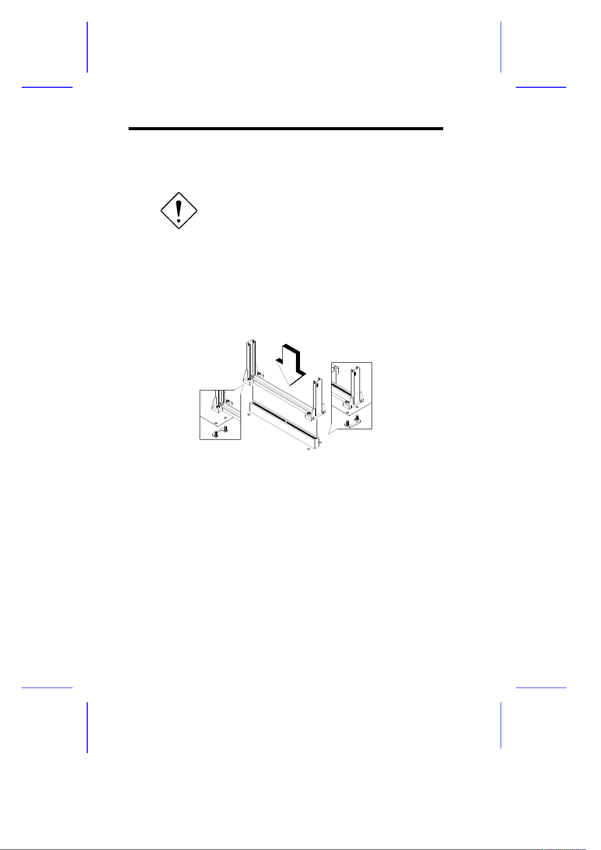
1.6.1 Installing a Pentium II Processor
Observe the ESD precautions when installing
or removing a system component.
Follow these steps to install a Pentium II processor:
1. Place the retention mechanism over the CPU connector on the
system board. Secure it with the screws that came with the
package.
Figure 1-3 Installing the Retention Mechanism
2. Remove the Pentium II processor from its protective packaging.
Make sure that the latches on the sides of the module are not
pressed.
3. With the processor card golden fingers pointing downward, align
the processor to the posts of the retention mechanism.
4. Lower the processor into to the CPU connector on the system
board until the golden fingers touch the connector.
1-10 User’s Guide
Page 24
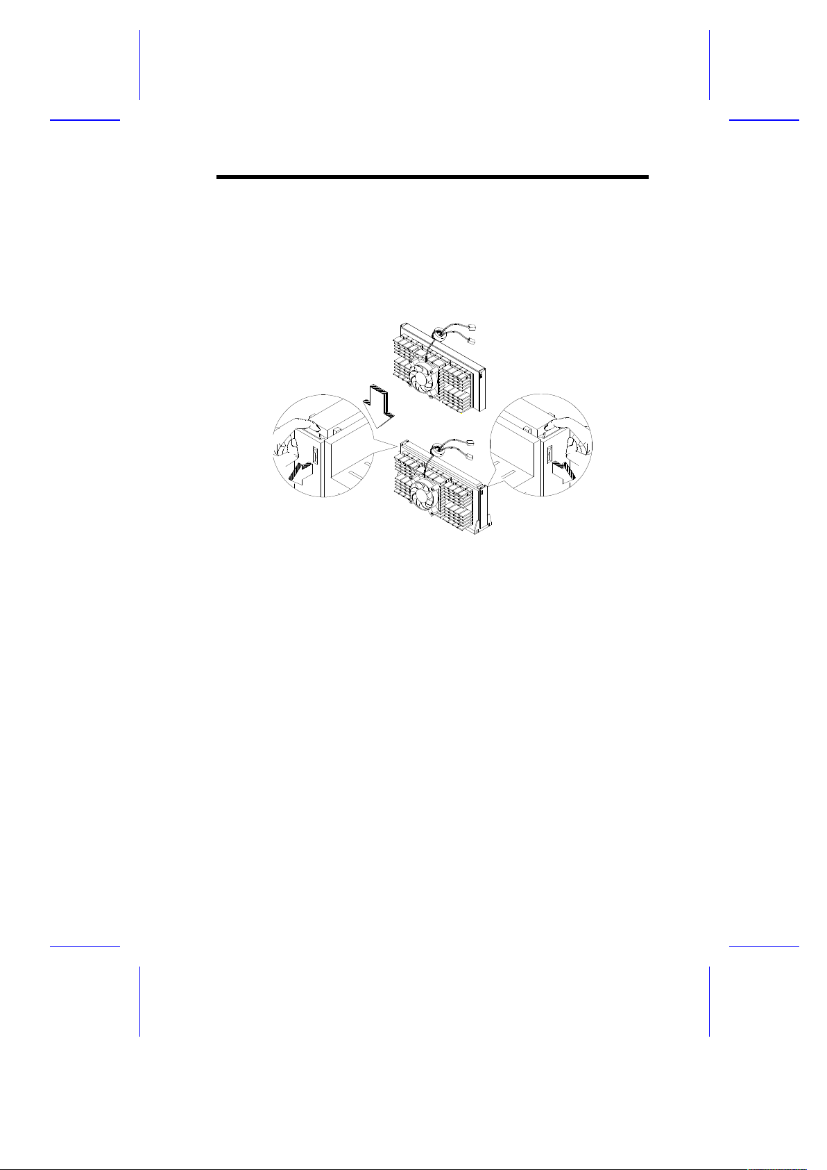
5. Press down the processor until the golden fingers completely fit
into the connector and the latches on the sides lock the processor
into place.
Figure 1-4 Installing a Pentium II Processor
System Board 1-11
Page 25
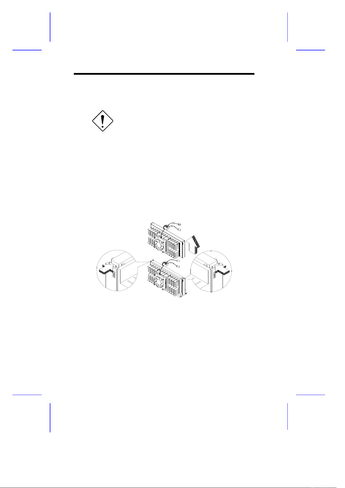
1.6.2 Removing a Pentium II Processor
Observe the ESD precautions when installing
or removing a system component.
Follow these steps to remove the Pentium II processor:
1. Press the latches on both sides of the processor to release it from
the retention mechanism. You will hear a click sound once the
latch is released.
2. Pull the processor to totally detach it from the CPU connector.
Figure 1-5 Removing a Pentium II Processor
1-12 User’s Guide
Page 26

1.7 Memory Configurations
The system board comes with six 72-pin SIMM sockets that allows you
to expand memory to a maximum of 384 MB. The SIMM sockets
support 5V FPM/EDO DRAMs with 4-, 8-, 16-, 32-, and 64-MB
capacities and 60ns (or less) access time. The FPM DRAM is the
standard DRAM type. The EDO DRAM is actually very similar to FPM.
The only difference is that EDO DRAM holds the memory data valid
until the next memory access cycle, that is similar to pipeline effect
and therefore reduces one clock state, while traditional FPM tri-states
the memory output data to start the pre-charge activity.
Table 1-3 lists the possible memory configurations.
1.7.1 Rules for Adding Memory
· Use only one type of SIMM in a given bank.
· You may combine different types of SIMMs for a memory
configuration as long as the SIMMs in each bank are of the
same type.
· Always install SIMMs in pairs. For example, for a total memory of
8 MB, install two 4-MB SIMMs into the sockets marked
SIMM1 and SIMM2 or SIMM3 and SIMM4. You can not use
an 8-MB SIMM alone for an 8-MB memory.
· Always install SIMMs from the outermost socket first. For
example, socket SIMM1 before socket SIMM2, or
socket SIMM3 before socket SIMM4.
· Always remove SIMMs from the innermost socket first. For
example, socket SIMM4 before socket SIMM3, or
socket SIMM2 before socket SIMM1.
System Board 1-13
Page 27

Table 1-3 Memory Configurations
Bank 1 Bank 2 Bank 3 Total
SIMM1 SIMM2 SIMM3 SIMM4 SIMM5 SIMM6 Memory
4 MB 4 MB 8 MB
4 MB 4 MB 4 MB 4 MB 16 MB
4 MB 4 MB 4 MB 4 MB 4 MB 4 MB 24 MB
8 MB 8 MB 16 MB
8 MB 8 MB 4 MB 4 MB 24 MB
8 MB 8 MB 4 MB 4 MB 4 MB 4 MB 32 MB
8 MB 8 MB 8 MB 8 MB 32 MB
8 MB 8 MB 8 MB 8 MB 4 MB 4 MB 40 MB
8 MB 8 MB 8 MB 8 MB 8 MB 8 MB 48 MB
16 MB 16 MB 32 MB
16 MB 16 MB 4 MB 4 MB 40 MB
16 MB 16 MB 4 MB 4 MB 4 MB 4 MB 48 MB
16 MB 16 MB 8 MB 8 MB 48 MB
16 MB 16 MB 8 MB 8 MB 4 MB 4 MB 56 MB
16 MB 16 MB 8 MB 8 MB 8 MB 8 MB 64 MB
16 MB 16 MB 16 MB 16 MB 64 MB
16 MB 16 MB 16 MB 16 MB 4 MB 4 MB 72 MB
16 MB 16 MB 16 MB 16 MB 8 MB 8 MB 80 MB
16 MB 16 MB 16 MB 16 MB 16 MB 16 MB 96 MB
32 MB 32 MB 64 MB
32 MB 32 MB 4 MB 4 MB 72 MB
32 MB 32 MB 4 MB 4 MB 4 MB 4 MB 80 MB
32 MB 32 MB 8 MB 8 MB 80 MB
32 MB 32 MB 8 MB 8 MB 4 MB 4 MB 88 MB
32 MB 32 MB 8 MB 8 MB 8 MB 8 MB 96 MB
32 MB 32 MB 16 MB 16 MB 96 MB
32 MB 32 MB 16 MB 16 MB 4 MB 4 MB 104 MB
32 MB 32 MB 16 MB 16 MB 8 MB 8 MB 112 MB
1-14 User’s Guide
Page 28

Table 1-3 Memory Configurations (continued)
Bank 1 Bank 2 Bank 3 Total
SIMM1 SIMM2 SIMM3 SIMM4 SIMM5 SIMM6 Memory
32 MB 32 MB 16 MB 16 MB 16 MB 16 MB 128 MB
32 MB 32 MB 32 MB 32 MB 128 MB
32 MB 32 MB 32 MB 32 MB 4 MB 4 MB 136 MB
32 MB 32 MB 32 MB 32 MB 8 MB 8 MB 144 MB
32 MB 32 MB 32 MB 32 MB 16 MB 16 MB 160 MB
32 MB 32 MB 32 MB 32 MB 32 MB 32 MB 192 MB
64 MB 64 MB 128 MB
64 MB 64 MB 4 MB 4 MB 136 MB
64 MB 64 MB 4 MB 4 MB 4 MB 4 MB 144 MB
64 MB 64 MB 8 MB 8 MB 144 MB
64 MB 64 MB 8 MB 8 MB 4 MB 4 MB 152 MB
64 MB 64 MB 8 MB 8 MB 8 MB 8 MB 160 MB
64 MB 64 MB 16 MB 16 MB 160 MB
64 MB 64 MB 16 MB 16 MB 4 MB 4 MB 168 MB
64 MB 64 MB 16 MB 16 MB 8 MB 8 MB 176 MB
64 MB 64 MB 16 MB 16 MB 16 MB 16 MB 192 MB
64 MB 64 MB 32 MB 32 MB 192 MB
64 MB 64 MB 32 MB 32 MB 4 MB 4 MB 200 MB
64 MB 64 MB 32 MB 32 MB 8 MB 8 MB 208 MB
64 MB 64 MB 32 MB 32 MB 16 MB 16 MB 224 MB
64 MB 64 MB 32 MB 32 MB 32 MB 32 MB 256 MB
64 MB 64 MB 64 MB 64 MB 256 MB
64 MB 64 MB 64 MB 64 MB 4 MB 4 MB 264 MB
64 MB 64 MB 64 MB 64 MB 8 MB 8 MB 272 MB
64 MB 64 MB 64 MB 64 MB 16 MB 16 MB 288 MB
64 MB 64 MB 64 MB 64 MB 32 MB 32 MB 320 MB
64 MB 64 MB 64 MB 64 MB 64 MB 64 MB 384 MB
System Board 1-15
Page 29
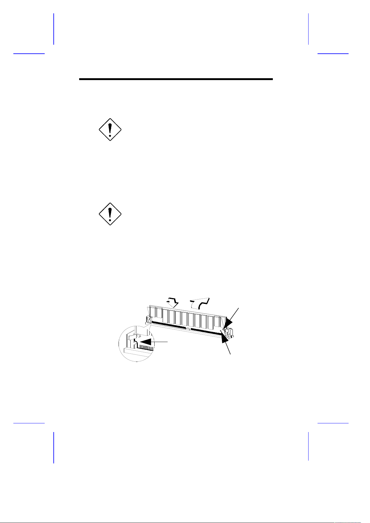
1.7.2 Installing a SIMM
Observe the ESD precautions when installing
or removing a system component.
Follow these steps to install a SIMM:
1. Carefully slip a SIMM at a 45° angle into a socket making sure
that the curved edge indicating the pin 1 of the SIMM matches
pin 1 of the socket.
A SIMM fits only in one direction. If you slip
in a SIMM but would not completely fit, you
may have inserted it the wrong way. Reverse
the orientation of the SIMM.
2. Gently push the SIMM to a vertical position until the pegs of the
socket slip into the holes on the SIMM, and the holding clips lock
the SIMM into position. The SIMM should be at a 90° angle when
installed.
1-16 User’s Guide
Hole
Peg
Pin 1 Indicator
(curved edge)
1
2
Page 30

Figure 1-6 Installing a SIMM
System Board 1-17
Page 31
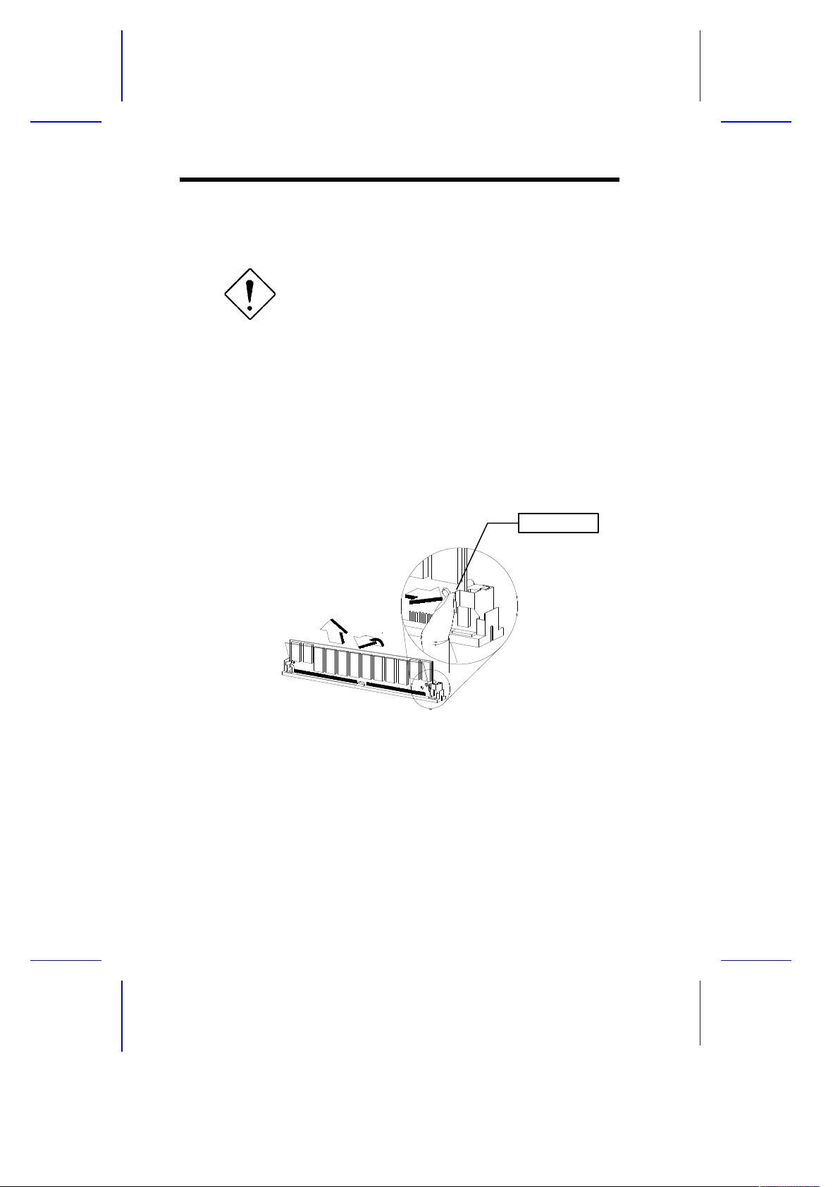
1.7.3 Removing a SIMM
Observe the ESD precautions when installing
or removing a system component.
Follow these steps to remove a SIMM
1. Press the holding clips on both sides of the SIMM outward to
release it.
2. Move the SIMM to a 45° angle.
3. Pull the SIMM out of the socket.
Figure 1-7 Removing a SIMM
1-18 User’s Guide
1
2
3
Holding Clip
Page 32
1.7.4 Reconfiguring the System
You must enter Setup after installing or removing SIMMs to
reconfigure the system.
Follow these steps to reconfigure the system:
1. Turn on the system. A memory error message appears,
indicating that the total memory does not match the value stored
in CMOS.
2. Press + + to enter Setup. A warning message
appears indicating a wrong memory configuration.
3. Press twice to exit and reboot the system.
The system boots with the new memory configuration.
1.8 IDE Hard Disk Support
The system board supports four IDE hard disks, or any other IDE
devices, through the two onboard PCI IDE interfaces. See Figure 1-2
for the location of the IDE interfaces.
Follow the instructions in the housing installation manual on how to
install a hard disk in the system. Connect the cables according to the
IDE hard disk configuration in Table 1-4.
Table 1-4 IDE Hard Disk Configuration
IDE Connector Master Slave
HDD Channel 1 Hard disk 0 Hard disk 1
HDD Channel 2 Hard disk 2 Hard disk 3/
IDE CD-ROM drive
System Board 1-19
Page 33

1.9 Add-on Card Installation
Observe the ESD precautions when installing
or removing a system component.
1.9.1 Installing ISA Cards
Both PnP and non-PnP ISA cards require specific IRQs. When
installing ISA cards make sure that the IRQs required by these cards
are not previously assigned to PCI devices to avoid resource conflicts.
Follow these steps when installing ISA cards:
1. Turn off the system and remove all PnP cards installed, if any.
2. Turn on the system, enter BIOS utility and set the Reset
Resource Assignment parameter to Yes to clear the resource
data assigned to the PnP devices. Refer to section 2.4.5.
3. Turn off the system.
4. Locate the ISA slots on the system board and install the non-PnP
ISA cards.
5. Turn on the system.
6. Use Windows 95 or ICU to manually assign the appropriate IRQs
to the cards. This ensures that BIOS will not use the resources
assigned to the non-PnP ISA cards.
BIOS detects and configures only PnP cards.
1-20 User’s Guide
Page 34
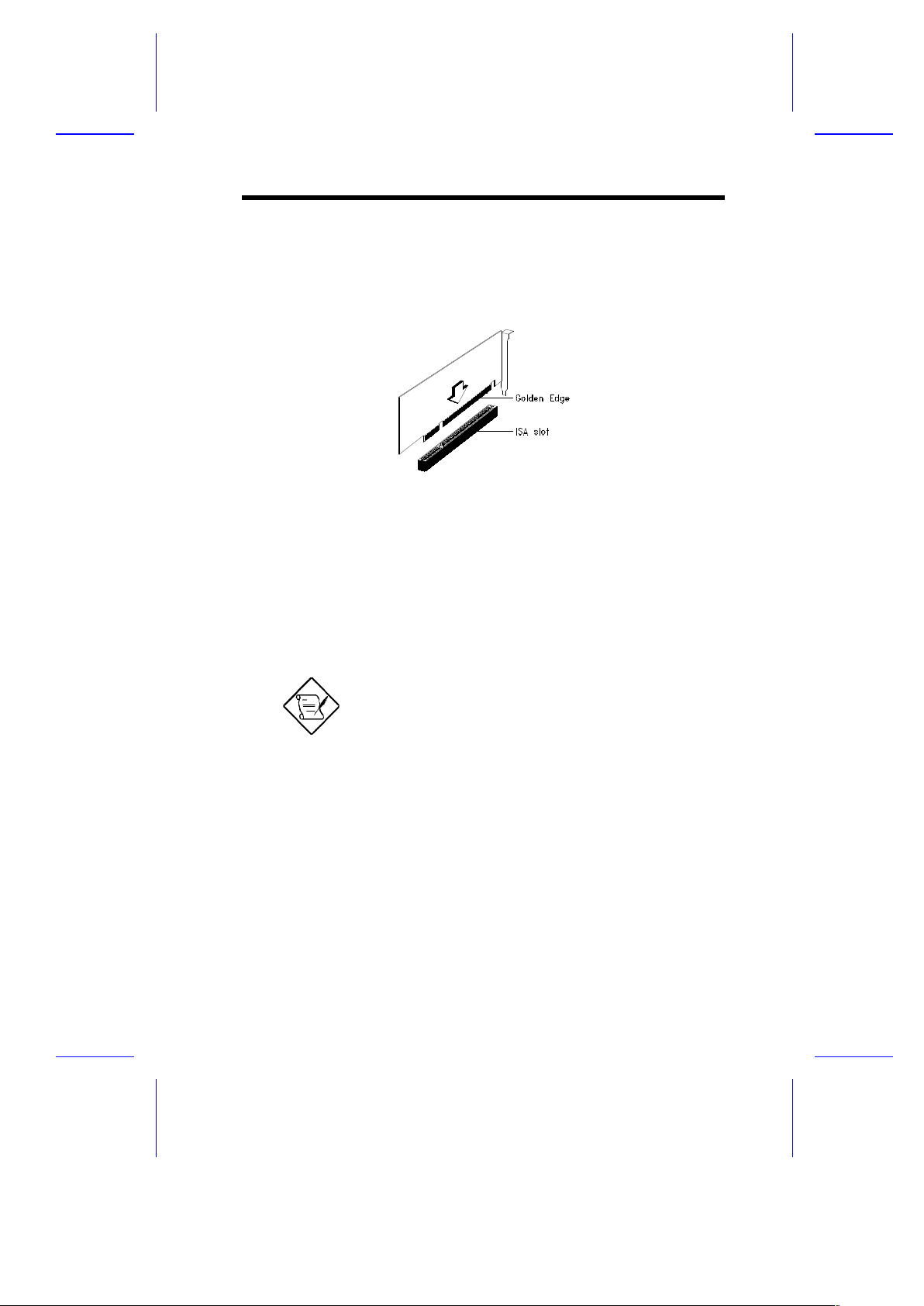
7. Turn off the system.
8. Locate the ISA slots on the system board and install the PnP ISA
cards.
Figure 1-8 Installing an ISA Card
9. Turn on the system. This time PnP BIOS automatically
configures the PnP ISA cards with the remaining free IRQs.
1.9.2 Installing a PCI Card
Before you proceed, make sure that you have
already installed the non-PnP ISA cards and
have assigned the appropriate IRQs to the
cards.
Follow these steps to install a PCI card:
1. Turn off the system.
2. Locate the PCI slot on the system board.
3. Align the golden fingers of the PCI card to the slot.
4. Press the PCI card until it is properly seated.
System Board 1-21
Page 35
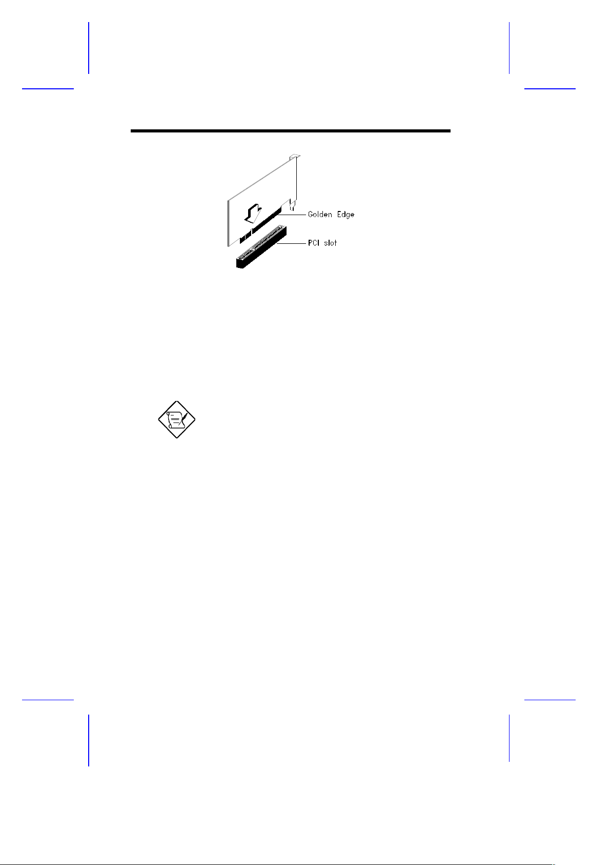
Figure 1-9 Installing a PCI Card
5. Turn on the system. The PnP BIOS automatically configures the
PnP ISA and PCI cards with the remaining free IRQs.
1.9.3 Installing a SCSI/LAN Card
Before you proceed, make sure that you have
already installed the non-PnP ISA cards and
have assigned the appropriate IRQs to the
cards.
To take full advantage of the board’s SCSI and network functions, you
need to install a SCSI/LAN combo card. To install, follow these steps:
1. Turn off the system.
2. Locate the SCSI/LAN card slot on the system board.
3. Align the golden fingers of the SCSI/LAN card to the slot.
4. Press the card until it is properly seated.
1-22 User’s Guide
Page 36
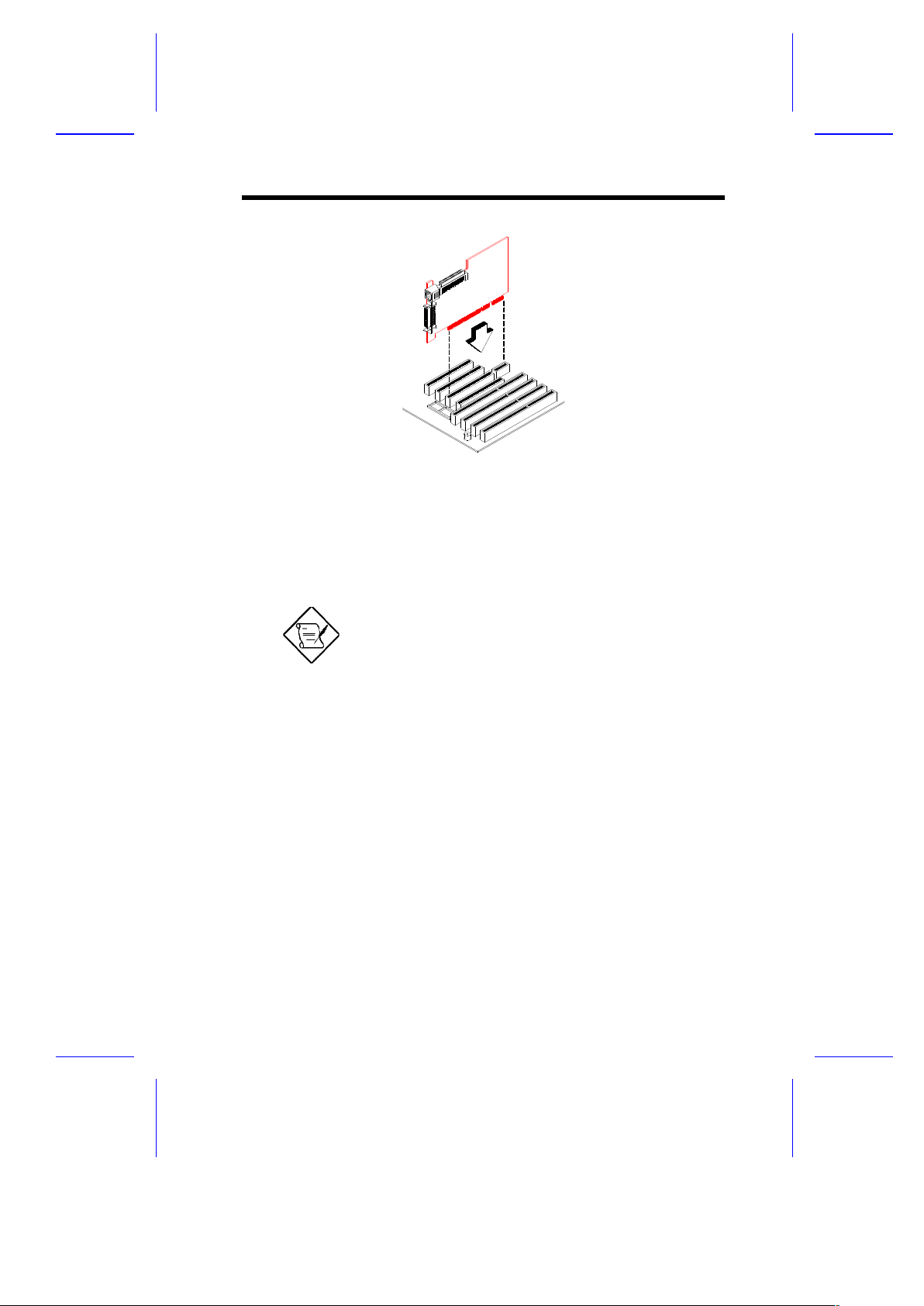
Figure 1-10 Installing a SCSI/LAN Card
5. Turn on the system. The PnP BIOS automatically configures the
installed card with the remaining free IRQs.
Refer to you SCSI/LAN combo card user’s
guide for detailed information on SCSI/LAN
functions.
Special Instruction After Installing the SCSI/LAN Card
If you installed a SCSI/LAN card in your system, only PCI cards that
support IRQ sharing function can be installed on PCI slot 4.
Before you install a PCI card on PCI slot 4, make sure that you do the
following:
· Read your card documentation and check if your PCI card
supports the PCI IRQ sharing function.
· Set the PCI IRQ Sharing parameter in the BIOS Setup to Yes. For
more details on BIOS, see Chapter 2.
System Board 1-23
Page 37

1.10 Post-installation Instructions
Observe the following after installing a system component:
1. See to it that the components are installed according to the stepby-step instructions in their respective sections.
2. Make sure you have set all the required jumpers. See section
1.3.2 for the correct jumper settings.
3. Replace any expansion boards or peripherals that you removed
earlier.
4. Replace the system cover.
5. Connect the necessary cables and turn on the system.
1.11 USB
USB is a new serial bus design that is capable of cascading
low-/medium-speed peripherals (less than 12 Mbps) such as
keyboard, mouse, joystick, scanner, printer and modem/ISDN. With
USB, complex cable connections at the back panel of your PC can be
eliminated.
See Figure 1-1 for the location of the USB interface on the system
board.
1-24 User’s Guide
Page 38

1.12 Hardware Monitor Function
The hardware monitor function of the system board allows you to
check the system resources, either locally or in a computer network,
via software called ADM (Advanced Desktop Management) or Intel
LDCM (LAN Desk Client Manager) ). ADM and Intel LDCM are
desktop management programs that offer SMART (System Monitoring
Analysis and Reporting Technology) monitor function for checking
local or network connected systems. In addition, it also enables the
PC products and applications to be OS independent.
To enable the hardware monitor function, you need to install either
ADM or Intel LDCM. Contact your dealer for information on the
availability of the software. Refer to the software documentation for
more details on the hardware monitor function.
1.13 Error Messages
In the event that you receive an error message, do not continue using
the computer. Note the message and take corrective action
immediately. This section describes the different types of error
messages and suggests corrective measures.
There are two general types of error messages:
· Software
· System
1.13.1 Software Error Messages
Software error messages are returned by your operating system or
application. These messages typically appear after you boot the
operating system or when you run your applications. If you receive
this type of message, consult your application or operating system
manual for help.
System Board 1-25
Page 39

1.13.2 System Error Messages
A system error message indicates a problem with the computer itself.
These messages normally appear during the power-on self-test,
before the operating system prompt appears. Table 1-5 lists the
system error messages in alphabetical order.
1-26 User’s Guide
Page 40

Table 1-5 System Error Messages
Message Action
CMOS Battery Error Replace the RTC chip or contact
your dealer.
CMOS Checksum Error Check the RTC chip and the
necessary jumper. If the battery is
still good, run Setup.
Display Card Mismatch Run Setup
Diskette Drive Controller
Error or Not Installed
Check and connect the control
cable to the diskette controller.
Diskette Drive Error Diskette may be defective. If not,
replace the diskette drive.
Diskette Drive A Type
Mismatch
Run Setup and select the proper
drive type.
Diskette Drive B Type
Mismatch
Run Setup and select the proper
drive type.
Equipment
Configuration Error
Modify the memory configuration to
agree with one of the options in
Table 1-3.
Hard disk Controller
Error
Run Setup.
Hard disk 0 Error Check all cable connections.
Replace hard disk.
Hard disk 1 Error Check all cable connections.
Replace hard disk.
Keyboard Error or No
Keyboard Connected
Check and connect the keyboard to
the system unit.
System Board 1-27
Page 41
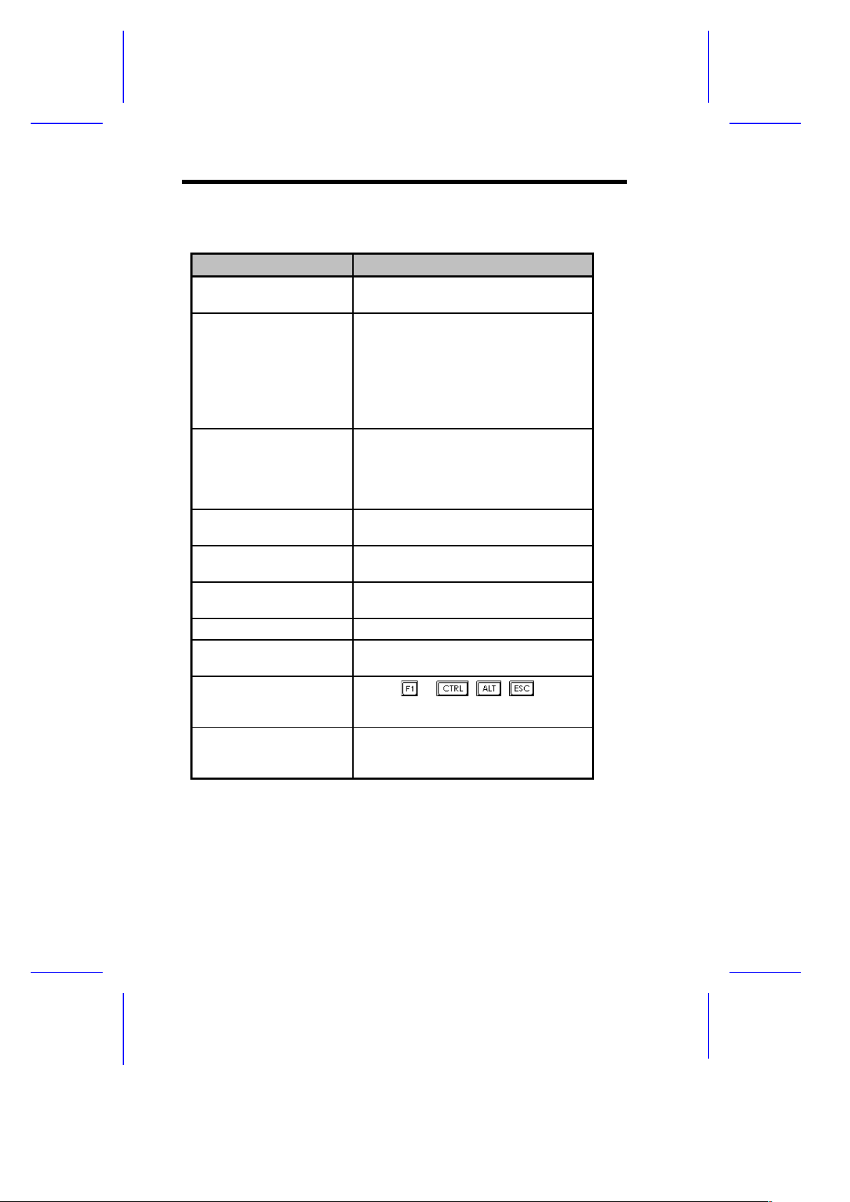
Table 1-5 System Error Messages (continued)
Message Action
Keyboard Interface
Error
Replace the keyboard or contact
your dealer.
Memory Error at:
MMMM:SSSS:OOO
(W:XXXX, R:YYYY)
where:
M: MB, S: Segment,
O: Offset,
X/Y: write/read pattern
Check SIMMs on the system board.
Contact your dealer.
CPU Clock Mismatch Run Setup. Check if the CPU clock is
correct. If correct, exit Setup and
reboot the system. If the error
message reappears, ask for technical
assistance.
Onboard Serial Port 1
Conflict
Run Setup and disable the port.
Onboard Serial Port 2
Conflict
Run Setup and disable the port.
Onboard Parallel Port
Conflict
Run Setup and disable the port.
Pointing Device Error Check and connect pointing device.
Pointing Device
Interface Error
Replace the pointing device or contact
your dealer.
Press F1 key to
continue or Ctrl-Alt-Esc
for Setup
Press or + + to enter
Setup.
Real Time Clock Error Check the RTC chip. If it is still good,
run Setup. If not, replace the RTC
chip.
1-28 User’s Guide
Page 42

1.13.3 Correcting Error Conditions
As a general rule, if an error message says "Press F1 to continue," it is
caused by a configuration problem, which can be easily corrected. An
equipment malfunction is more likely to cause a fatal error, i.e., an
error that causes complete system failure.
Here are some corrective measures for error conditions:
1. Run Setup. You must know the correct configuration values for
your system before you enter Setup, which is why you should
write them down when the system is correctly configured. An
incorrect configuration is a major cause of power-on error
messages, especially for a new system.
2. Remove the system unit cover. Check that the jumpers on the
system board and any expansion boards are set correctly.
3. If you cannot access a new disk, it may be because your disk is
not properly formatted. Format the disk first using the FDISK and
FORMAT commands.
4. Check that all connectors and boards are securely plugged in.
If you go through the corrective steps above and still receive an error
message, the cause may be an equipment malfunction.
If you are sure that your configuration values are correct and your
battery is in good condition, the problem may lie in a damaged or
defective chip.
In both cases, contact an authorized service center for assistance.
System Board 1-29
Page 43

C h a p t e r
2
BIOS Utility
Most systems are already configured by the manufacturer or the
dealer. There is no need to run Setup when starting the computer
unless you get a Run Setup message.
The Setup program loads configuration values into the battery-backed
nonvolatile memory called CMOS RAM. This memory area is not part
of the system RAM.
If you repeatedly receive Run Setup
messages, the battery may be bad. In this
case, the system cannot retain configuration
values in CMOS. Ask a qualified technician
for assistance.
Before running Setup, have the following information ready:
· Diskette drive type The standard type is either a 5.25-inch
1.2-MB or a 3.5-inch 1.44/2.88-MB diskette drive.
· IDE hard disk drive type The drive information is on the label
pasted on your IDE drive or in the documentation supplied by
the vendor.
BIOS Utility 2-1
Page 44
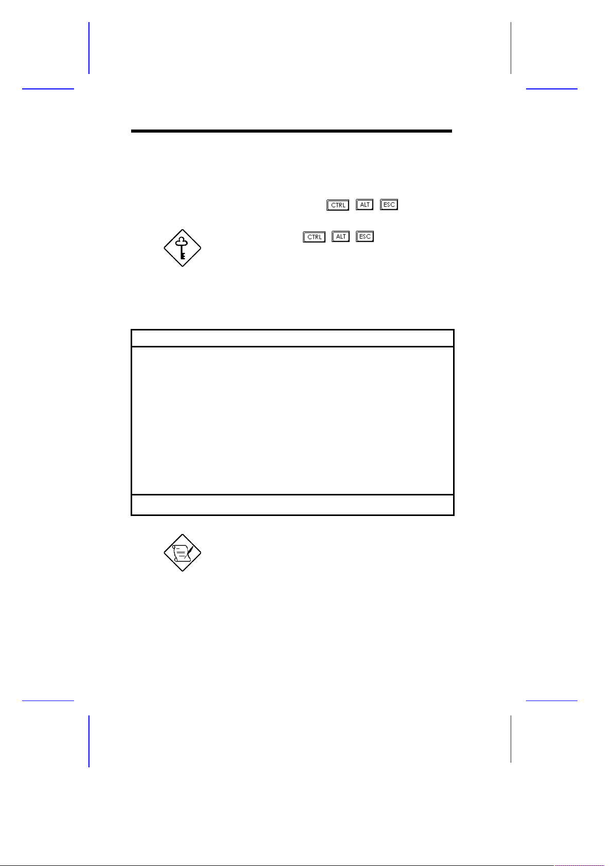
2.1 Entering Setup
To enter Setup, press the key combination + + .
You must press + +
while the
system is booting. This key combination
does not work during any other time.
The BIOS Utility main menu then appears:
BIOS Utility
Basic System Configuration
Advanced System Configuration
PnP/PCI System Configuration
Power Saving Configuration
System Security
Load Setup Default Settings
¯¬® = Move Highlight Bar, ¿ = Select, Esc = Exit and Reboot
The parameters on the screens show default
values. These values may not be the same
as those in your system.
The grayed items on the screens have fixed
settings and are not user-configurable.
2-2 User’s Guide
Page 45
2.2 Basic System Configuration
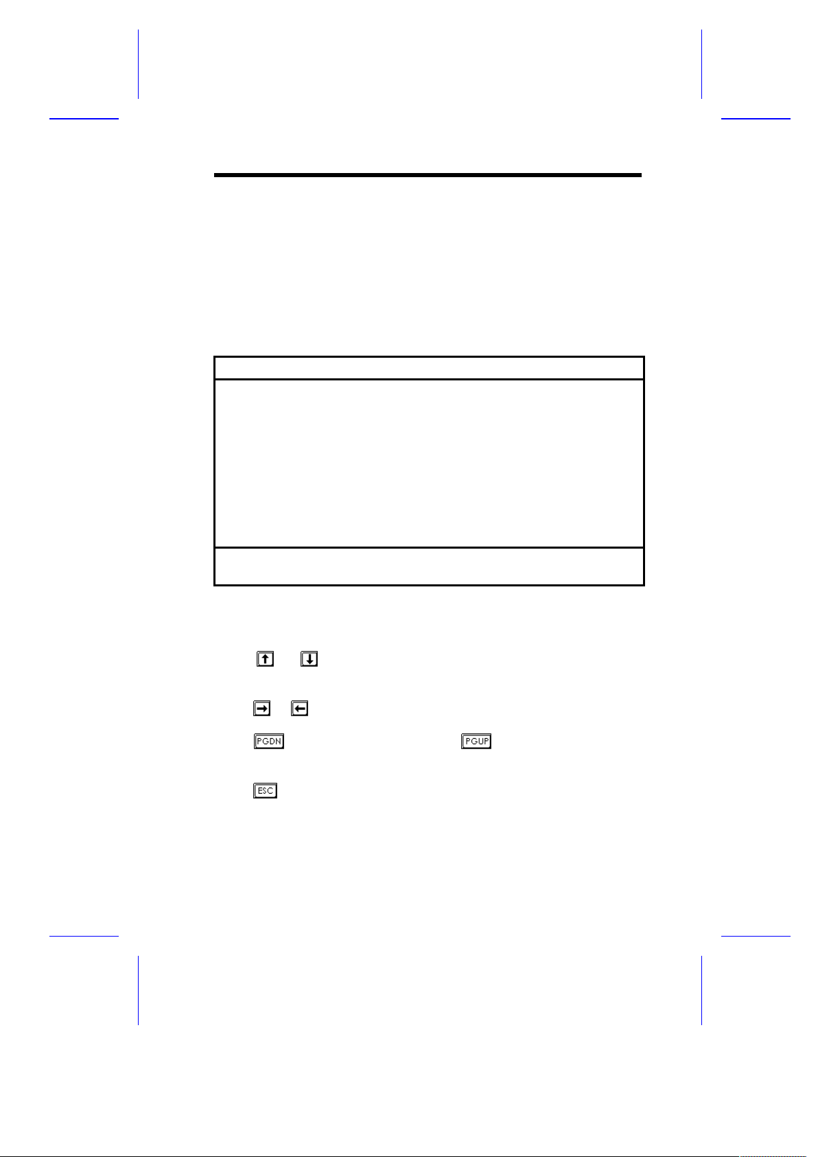
Select Basic System Configuration to input configuration values such
as date, time, and disk types.
The following screen shows the Basic System Configuration menu.
Basic System Configuration Page 1/2
Date ......................[MM/DD/YY]
Time ......................[HH:MM:SS]
Diskette Drive A ..........[xx-MB xx-inch]
Diskette Drive B ..........[xx-MB xx-inch]
Cylinder Head Sector
IDE Drive 0 (xxx MB)......[Auto] xx xx xx
IDE Drive 1 (xxx MB)......[Auto] xx xx xx
IDE Drive 2 (xxx MB)......[Auto] xx xx xx
IDE Drive 3 (xxx MB)......[Auto] xx xx xx
Total Memory ......... ....[ x ] MB
¯ = Move Highlight Bar, ® ¬ = Change Setting
PgDn/PgUp = Move Screen, F1 = Help, Esc = Exit
The command line at the bottom of the menu tells you how to highlight
items, change settings, and move from one screen to another.
Press or on the cursor-edit keypad to highlight the desired
parameter.
Press or to select the desired option for a parameter.
Press to move to the next page or to return to the previous
page.
Press to exit the configuration menu.
BIOS Utility 2-3
Page 46

The following screen shows page 2 of the Basic System Configuration
menu.
Basic System Configuration Page 2/2
Enhanced IDE Features
Hard Disk Block Mode ...........[Enabled ]
Advanced PIO Mode ..............[Enabled ]
Hard Disk Size > 504MB .........[Enabled ]
Hard Disk 32-Bit Access ....... .[Enabled ]
Num Lock After Boot ...............[Enabled ]
Memory Test .......................[Disabled]
Quiet Boot ........................[Enabled ]
Configuration Table ...............[Enabled ]
¯ = Move Highlight Bar, ® ¬ = Change Setting
PgDn/PgUp = Move Screen, F1 = Help, Esc = Exit
The following sections explain the different parameters and their
settings.
2.2.1 Date and Time
The real-time clock keeps the system date and time. After setting the
date and time, you do not need to enter them every time you turn on
the system. As long as the internal battery remains good
(approximately seven years) and connected, the clock continues to
keep the date and time accurately even when the power is off.
Date
Highlight the items on the Date parameter and press or to set
the date following the month-day-year format.
Valid values for month, day, and year are:
· Month 1 to 12
· Day1 to 31
2-4 User’s Guide
Page 47

· Year 00 to 99
Time
Highlight the items on the Time parameter and press or to set
the time following the hour-minute-second format.
Valid values for hour, minute, and second are:
· Hour 00 to 23
· Minute 00 to 59
· Second 00 to 59
2.2.2 Diskette Drives
To enter the configuration value for the first diskette drive (drive A),
highlight the Diskette Drive A parameter. Press or key to view
the options and select the appropriate value.
Possible settings for the Diskette Drive parameters:
· [ None ]
· [360 KB, 5.25-inch]
· [1.2 MB, 5.25-inch]
· [720 KB, 3.5-inch]
· [1.44 MB, 3.5-inch]
Follow the same procedure for Diskette Drive B. Choose None if you
do not have a second diskette drive.
2.2.3 IDE Drives
Move the highlight bar to the IDE Drive 0 parameter to configure the
first IDE drive (drive C). Press or to display the IDE drive types
with their respective values. Select the type that corresponds to your
IDE hard disk drive. Follow the same procedure for the other IDE hard
disk drives, if any. Choose None for IDE drives other than hard disk
and CD-ROM.
BIOS Utility 2-5
Page 48
Selecting the “Auto” Option
If you do not know the exact type of your IDE hard disk drive, select
the option Auto. During the power-on self-test (POST), when the
system performs self-testing and self-initialization before loading the
operating system and applications, the BIOS utility automatically
determines your IDE drive type. You can see the drive type and its
values when you enter the BIOS Utility.
Cylinder Head Sector
IDE Drive 0 (xx MB). ...[Auto] xx xx xx
If desired, you can save the values under the option User.
Cylinder Head Sector
IDE Drive 0 (xx MB). ...[User] xx xx xx
The next time you boot the system, the BIOS utility does not have to
auto-configure your IDE drive as it detects the saved disk information
during POST.
We recommend that you copy the IDE disk
drive values and keep them in a safe place in
case you have to reconfigure the disk in the
future.
Follow the same procedure to auto-configure other IDE drives.
2-6 User’s Guide
Page 49

Selecting the “User” Option
There are cases when you cannot use the option Auto, instead you
have to select User. Choose the User option when you have installed
an IDE hard disk that was previously formatted but does not use the
disk native parameters or structure, that is, the disk may be formatted
according to the user specified number of cylinders, heads, and
sectors.
Follow these steps to configure an IDE hard disk with the User
option:
1. Highlight an IDE drive parameter.
2. Select the option User and press .
3. Type in the number of cylinders, heads, and sectors of the drive
under the appropriate columns.
Be sure to have the correct IDE hard disk
drive information beforehand.
4. Choose Yes when asked if you want to save CMOS data.
2.2.4 Total Memory
The system automatically detects the total amount of onboard memory
during the POST and sets this parameter accordingly. If you install
additional memory, the system automatically adjusts this parameter to
display the new memory size.
BIOS Utility 2-7
Page 50

2.2.5 Enhanced IDE Features
Hard Disk Block Mode
This function enhances disk performance depending on the hard disk
in use. If you set this parameter to Enabled, it allows data transfer in
block (multiple sectors) by increasing the data transfer rate to 256
bytes per cycle. If your system does not boot after enabling this
parameter, this means that your HDD cannot support the function.
Therefore, you must change the setting to Disabled.
Advanced PIO Mode
Enabling this parameter allows for faster data recovery and read/write
timing that reduces hard disk activity time. This results to better hard
disk performance.
To utilize this feature, your hard disk must support the advanced PIO
mode. If not, set this parameter to Disabled. Refer to your hard disk
documentation for information about the advanced PIO mode.
Hard Disk Size > 504 MB
This enhanced IDE feature works only under DOS and Windows 3.x
environment. If enabled, it allows you to use a hard disk with a
capacity of more than 504 MB. This is made possible through the
Logical Block Address (LBA) mode translation. Other operating
systems require this parameter to be set to Disabled.
Hard Disk 32-bit Access
Enabling this parameter improves system performance by allowing
the use of the 32-bit hard disk access. This enhanced IDE feature
works only under DOS, Windows 3.x and Novell NetWare. If your
software or hard disk does not support this function, set this parameter
to Disabled .
2-8 User’s Guide
Page 51

2.2.6 Num Lock After Boot
This parameter allows you to activate the Num Lock function upon
booting. The default setting is Enabled.
2.2.7 Memory Test
When set to Enabled, this parameter allows the system to perform a
RAM test during the POST routine. When set to Disabled, the
system detects only the memory size and bypasses the test routine.
The default setting is Disabled .
2.2.8 Quiet Boot
This parameter enables or disables the quiet boot function. When set
to Enabled, BIOS is in graphical mode and displays only an
identification logo during POST and while booting. After which the
screen displays the operating system prompt (such as DOS) or logo
(such as Windows 95). If any error occurred while booting, the system
automatically switches to the text mode.
Even if your setting is Enabled, you may also switch to the text mode
while booting by pressing after you hear a beep that indicates the
activation of the keyboard.
When set to Disabled, BIOS is in the conventional text mode where
you see the system initialization details on the screen.
BIOS Utility 2-9
Page 52

2.2.9 Configuration Table
This parameter allows you to display the configuration table after
POST but before booting. The configuration table gives a summary of
the hardware devices and settings that BIOS detected during POST.
A sample configuration table appears below.
CPU ID : Pentium II
CPU Clock : 233 MHz
Math Coprocessor:Installed
IDE Drive 0 : xxx MB
IDE Drive 1 : xxx MB
IDE Drive 2 : xxx MB
IDE Drive 3 : xxx MB
Diskette Drive A: xx MB, xx-inch
Diskette Drive B: None
Pointing Device: None
ECC/Parity Mode: Disabled
Base Memory: : xxx KB
Extended Memory: xxxx KB
Shadow RAM : xxx KB
L1 (CPU) Cache : xxx KB, Enabled
L2 (CPU) Cache : xxx KB, Enabled
Serial Port(s) : 3F8h, 2F8h
Parallel Port(s): 378h
DRAM Bank 0 : Fast Page Mode
DRAM Bank 1 : None
DRAM Bank 2 : None
USB HC : Disabled
2-10 User’s Guide
Page 53
2.3 Advanced System Configuration
The Advanced System Configuration option allows you to configure
the advanced system memory functions.
Do not change any settings in the Advanced
Configuration if you are not a qualified
technician to avoid damaging the system.
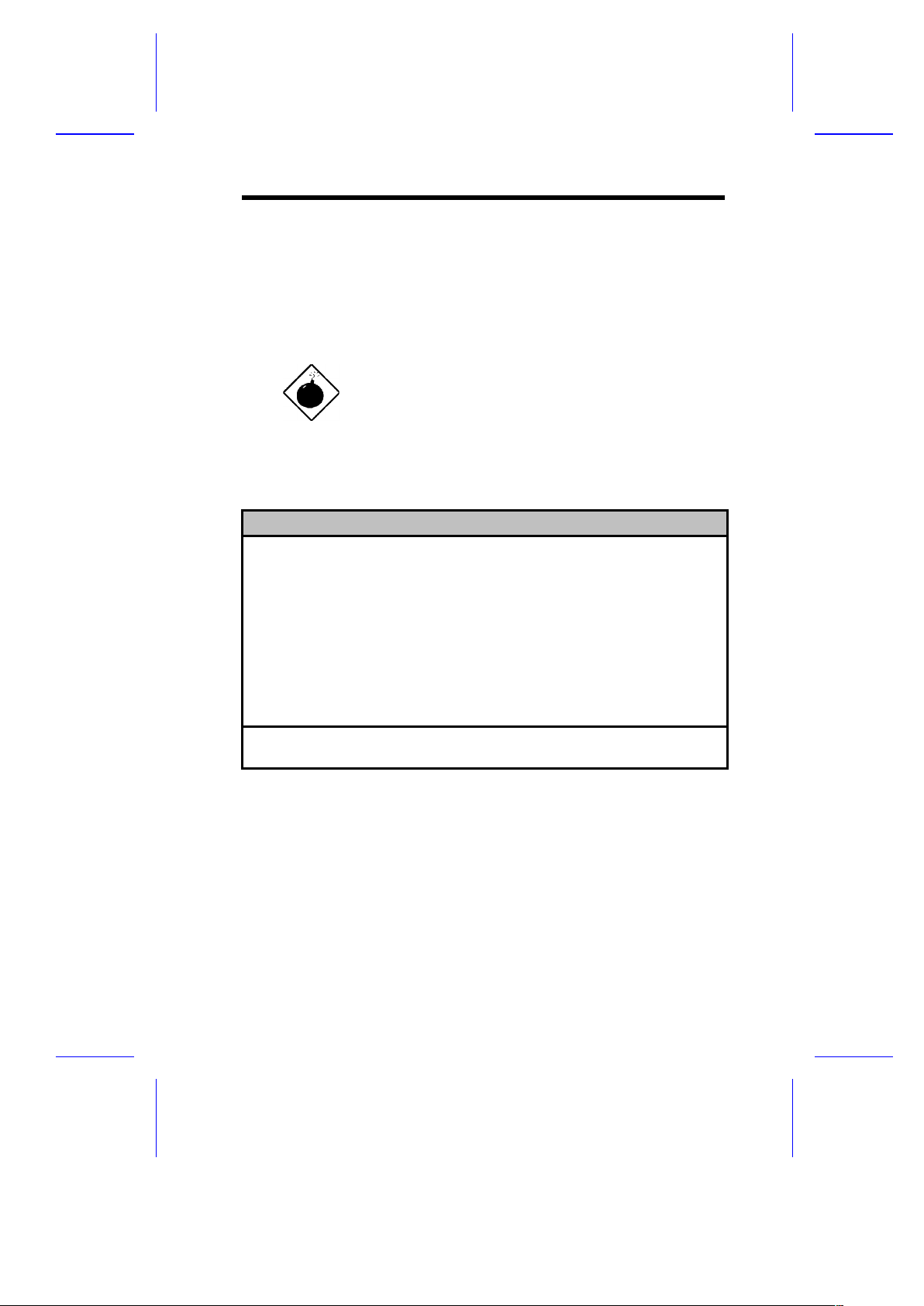
The following screen shows the Advanced System Configuration
parameters.
Advanced System Configuration Page 1/1
L1 Cache (CPU Cache)........ .... .... [Enabled ]
L2 Cache ........................... [Enabled ]
Cache Scheme .................... [Write Back ]
ECC/Parity Mode Selection ..... ..... [Disabled]
Memory at 15MB-16MB Reserved for . . . [System] Use
USB Host Controller......... .... .... [Disabled]
¯ = Move Highlight Bar, ® ¬ = Change Setting
PgDn/PgUp = Move Screen, F1 = Help, Esc = Exit
2.3.1 L1 Cache (CPU Cache)
This parameter enables or disables the first-level or internal memory,
that is, the memory integrated into the CPU. The default setting is
Enabled.
BIOS Utility 2-11
Page 54

2.3.2 L2 Cache
This parameter enables or disables the external cache memory. The
external cache is incorporated in the CPU module.
Cache Scheme
This parameter sets the cache to Write-through or Write-back
modes. Write-back updates the cache but not the memory when
there is a write instruction. It updates the memory only when there is
an inconsistency between the cache and the memory.
Write-through updates both the cache and the memory whenever
there is a write instruction.
2.3.3 ECC/Parity Mode Selection
This parameter allows you to enable or disable the ECC and parity
check features. Select Parity to enable the parity check feature.
Select ECC to enable the ECC feature. The ECC feature enables
BIOS to detect and correct data errors.
Disable this parameter if you installed SIMMs without parity or if you
want to disregard the function.
2.3.4 Memory at 15MB-16MB Reserved For
To prevent memory address conflicts between the system and
expansion boards, reserve this memory range for the use of either the
system or an expansion board.
2.3.5 USB Host Controller
This parameter lets you enable or disable the USB controller. The
USB function allows your system to support additional peripherals.
The default setting is Disabled.
2-12 User’s Guide
Page 55
2.4 PnP/PCI System Configuration
The PnP/PCI System Configuration allows you to specify the settings
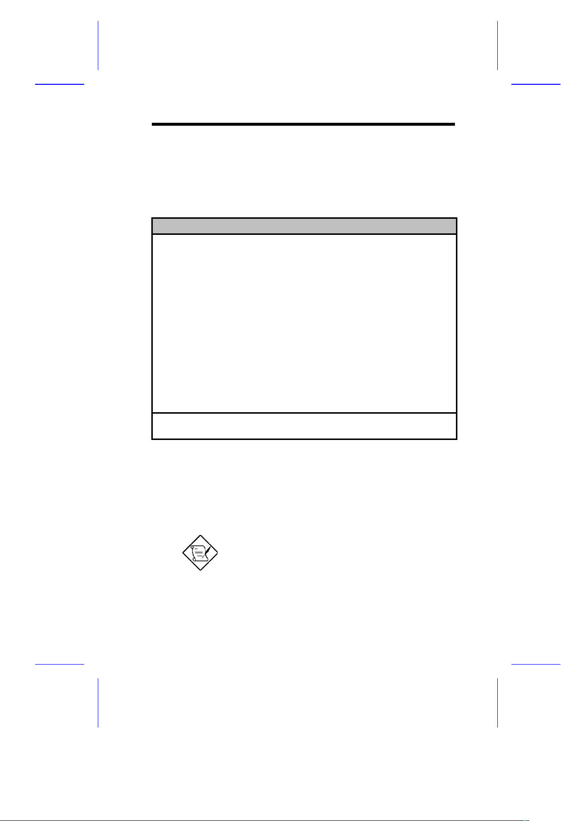
for your PCI devices.
PnP/PCI System Configuration Page 1/2
PCI IRQ Setting ............[ Auto ]
INTA INTB INTC INTD
PCI Slot 1...............[--] [--] [--] [--]
PCI Slot 2...............[--] [--] [--] [--]
PCI Slot 3...............[--] [--] [--] [--]
PCI Slot 4...............[--] [--] [--] [--]
PCI IRQ Sharing..............[No ]
VGA Palette Snoop ......... ..[Disabled]
Plug & Play OS...............[No ]
Reset Resources Assignment. . .[No ]
¯ = Move Highlight Bar, ® ¬ = Change Setting
PgDn/PgUp = Move Screen, F1 = Help, Esc = Exit
2.4.1 PCI IRQ Setting
This function is fixed at Auto setting and is nonconfigurable. It
automatically configures the plug-and-play (PnP) devices installed in
your system.
Refer to your manual for technical information
about the PCI card.
BIOS Utility 2-13
Page 56

PCI Slots
These parameters specify the auto-assigned interrupt for each of the
PCI devices. Like the PCI IRQ Setting parameter, these are also
nonconfigurable.
Onboard PCI Devices
This parameter specifies the auto-assigned interrupt for the onboard
PCI device(s) and is also nonconfigurable.
2.4.2 PCI IRQ Sharing
Setting this parameter to Yes allows you to assign the same IRQ to
two different devices. To disable the feature, select No.
If there are no IRQs available to assign for
the remaining device function, we
recommend that you enable this parameter.
2.4.3 VGA Palette Snoop
This parameter permits you to use the palette snooping feature if you
installed more than one VGA card in the system.
The VGA palette snoop function allows the control palette register
(CPR) to manage and update the VGA RAM DAC (Digital Analog
Converter, a color data storage) of each VGA card installed in the
system. The snooping process lets the CPR send a signal to all the
VGA cards so that they can update their individual RAM DACs. The
signal goes through the cards continuously until all RAM DAC data
have been updated. This allows display of multiple images on the
screen.
Some VGA cards have required settings for this
feature. Check your VGA card manual before
2-14 User’s Guide
Page 57

setting this parameter.
2.4.4 Plug & Play OS
When this parameter is set to Yes, BIOS initializes only PnP boot
devices such as SCSI cards. When set to No, BIOS initializes all PnP
boot and non-boot devices such as sound cards.
Set this parameter to Yes only if your operating
system is Windows 95.
2.4.5 Reset Resources Assignment
Set this parameter to Yes to avoid IRQ conflict when installing
non-PnP or PnP ISA cards. This clears all resource assignments and
allows BIOS to reassign resources to all installed PnP devices the next
time the system boots. After clearing the resource data, the parameter
resets to No.
Refer to section 1.9 for instructions on installing and configuring ISA
cards.
BIOS Utility 2-15
Page 58

2.5 Power Saving Configuration
The Power Saving Configuration parameters are configurable only if
your system supports the power-management feature.
The following screen shows the Power Saving Configuration
parameters and their default settings:
Power Saving Configuration Page 1/1
Power Management Mode ................[Enabled ]
IDE Hard Disk Standby Timer .. .. ...[ 15] Minute(s)
System Standby Timer ..............[ 15] Minute(s)
System Suspend Timer ..............[ 15] Minute(s)
Monitored Activities
*IRQ 0.. ... .. .[Disabled] IRQ 8 .......[Disabled]
*IRQ 1.. ... .. .[Enabled ] IRQ 9........[Disabled]
IRQ 3.. ... .. .[Disabled] IRQ 10.......[Disabled]
IRQ 4.. ... .. .[Disabled] IRQ 11.......[Disabled]
IRQ 5.. ... .. .[Disabled] IRQ 12.......[Enabled ]
*IRQ 6.. ... .. .[Enabled ] *IRQ 13.......[Enabled ]
IRQ 7.. ... .. .[Disabled] *IRQ 14.......[Enabled ]
IRQ 15.......[Disabled]
¯ = Move Highlight Bar, ® ¬ = Change Setting
PgDn/PgUp = Move Screen, F1 = Help, Esc = Exit
2.5.1 Power Management Mode
This parameter allows you to reduce power consumption. When this
parameter is set to Enabled, you can configure the IDE hard disk and
system timers. Setting to Disabled deactivates the
power-management feature and all the timers.
2-16 User’s Guide
Page 59

IDE Hard Disk Standby Timer
This parameter allows the hard disk to enter standby mode after
inactivity of 1 to 15 minutes, depending on your setting. When you
access the hard disk again, allow 3 to 5 seconds (depending on the
hard disk) for the disk to return to normal speed. Set this parameter to
Off if your hard disk does not support this function.
System Standby Timer
This parameter sets the system to a "fast-on power-saving mode. It
automatically enters into the standby mode after a specified period of
inactivity. Any keyboard or mouse action, or any enabled monitored
activities occurring through the IRQ channels resume system
operation. See section 2.5.2.
System Suspend Timer
This parameter sets the system to the lowest power-saving mode. It
automatically enters into the suspend mode after a specified period of
inactivity.
In suspend mode, the CPU clock stops. Any keyboard or mouse
action, or any enabled monitored activities occurring through the IRQ
channels resume system operation. See section 2.5.2.
2.5.2 Monitored Activities
The IRQ items under this parameter allow you to monitor system
activities occurring through the IRQ channels to determine whether or
not to enter power-saving mode.
For example, if you assign IRQ 3 to a fax/modem and you set this item
to Enabled, any fax/modem activity wakes up the system from
standby mode.
BIOS Utility 2-17
Page 60

2.6 System Security Setup
The Setup program has a number of security features to prevent
unauthorized access to the system and its data.
The following screen appears if you enter the Setup program and
select System Security.
System Security Page 1/1
Disk Drive Control
Diskette Drive................. [ Normal ]
Hard Disk Drive................ [ Normal ]
System Boot Drive........ ...... [Drive A then C]
Boot from CD-ROM......... ...... [Disabled]
Onboard Communication Ports
Serial Port 1 Base Address.. ... [ 3F8h ]
Serial Port 2 Base Address.. ... [ 2F8h ]
Parallel Port Base Address.. ... [378h (IRQ 7)]
Operation Mode..............[Standard Parallel Port (SPP)] Mode
ECP DMA Channel....... ...[-]
Onboard PS/2 Mouse (IRQ 12).. ... .[Enabled ]
Setup Password..... ............. .[ None ]
Power On Password........... .... .[ None ]
¯ = Move Highlight Bar, ® ¬ = Change Setting
PgDn/PgUp = Move Screen, F1 = Help, Esc = Exit
2.6.1 Disk Drive Control
The disk drive control features allow you to enable or disable the read/
write functions of a disk drive. These features can also control the
diskette drive or the hard disk drive boot function to prevent loading
operating systems or other programs from a certain drive while the
other drives are operational.
Table 2-1 lists the drive control settings and their corresponding
functions.
2-18 User’s Guide
Page 61
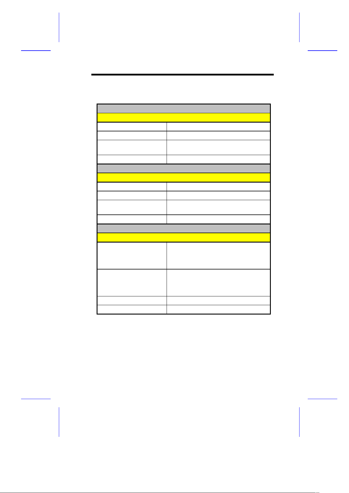
Table 2-1 Drive Control Settings
Diskette Drive
Setting Description
Normal Diskette drive functions normally
Write Protect All Sectors Disables the write function on all sectors
Write Protect Boot Sector Disables the write function only on the
boot sector
Disabled Disables all diskette functions
Hard Disk Drive
Setting Description
Normal Hard disk drive functions normally
Write Protect All Sectors Disables the write function on all sectors
Write Protect Boot Sector Disables the write function only on the
boot sector
Disabled Disables all hard disk functions
System Boot Drive
Setting Description
Drive A then C The system checks drive A first. If there
is a diskette in the drive, the system
boots from drive A. Otherwise, it boots
from drive C.
Drive C then A The system checks drive C first. If there
is a hard disk (drive C) installed, the
system boots from drive C. Otherwise, it
boots from drive A.
C: The system always boots from drive C.
A: The system always boots from drive A.
BIOS Utility 2-19
Page 62
Table 2-1 Drive Control Settings (continued)
Boot from CD-ROM
Setting Description
Enabled The system checks for a bootable CD in
the CD-ROM. If a CD is present, the
system boots from the CD-ROM.
Otherwise, it boots from the drive
specified in the System Boot Drive
parameter.
Disabled System boots from the drive specified in
the System Boot Drive parameter.
2.6.2 Onboard Communication Ports
Serial Port 1 Base Address
This parameter allows you to set the serial port 1 logical base address.
Table 2-2 Serial Port 1 Settings
Setting Description
3F8h Serial port 1 with address 3F8h using IRQ4
2F8h Serial port 1 with address 2F8h using IRQ3
3E8h Serial port 1 with address 3E8h using IRQ4
2E8h Serial port 1 with address 2E8h using IRQ3
Disabled Disables serial port 1
2-20 User’s Guide
Page 63
Serial Port 2 Base Address
This parameter allows you to set the serial port 2 logical base address.
Table 2-3 Serial Port 2 Settings
Setting Description
3F8h Serial port 2 with address 3F8h using IRQ4
2F8h Serial port 2 with address 2F8h using IRQ3
3E8h Serial port 2 with address 3E8h using IRQ4
2E8h Serial port 2 with address 2E8h using IRQ3
Disabled Disables serial port 2
If you assign 3F8h to serial port 1, you may
only assign 2F8h or 2E8h to serial port 2.
If you assign 2F8h to serial port 1, you may
only assign 3F8h or 3E8h to serial port 2.
Parallel Port Base Address
The system has one parallel port. Table 2-4 lists the options for
selecting the parallel port address. You also have the option to disable
the parallel port.
Table 2-4 Parallel Port Settings
Setting Function
3BCh (IRQ 7) Corresponds to the parallel port with
address 3BCh
378h (IRQ 7) Corresponds to the parallel port with
address 378h
278h (IRQ 5) Corresponds to the parallel port with
address 278h
BIOS Utility 2-21
Page 64
Disabled Disables the parallel port
To deactivate the parallel port, select the Disabled option. If you
install an add-on card that has a parallel port whose address conflicts
with the parallel port onboard, the system automatically disables the
onboard functions.
Check the parallel port address on the add-on card and change the
address to one that does not conflict.
OPERATION MODE
This item allows you to set the operation mode of the parallel port.
Table 2-5 lists the different operation modes.
Table 2-5 Parallel Port Operation Mode Settings
Setting Function
Standard Parallel Port (SPP) Allows normal speed one-way
operation
Standard and Bidirectional Allows normal speed operation in a
two-way mode
Enhanced Parallel Port (EPP) Allows bidirectional parallel port
operation at maximum speed
Extended Capabilities Port
(ECP)
Allows parallel port to operate in
bidirectional mode and at a speed
higher than the maximum data
transfer rate
ECP DMA CHANNEL
This item becomes active only if you select Extended Capabilities
Port (ECP) as the operation mode. It allows you to assign DMA
channel 1 or DMA channel 3 for the ECP parallel port function (as
required in Windows 95).
2-22 User’s Guide
Page 65
2.6.3 Onboard PS/2 Mouse (IRQ 12)
This parameter enables or disables the onboard PS/2 mouse. When
set to Enabled, it allows you to use the onboard PS/2 mouse
assigned with IRQ12. When set to Disabled, it deactivates the
mouse and makes IRQ12 available for use of other devices.
2.6.4 Setup Password
The Setup Password prevents unauthorized access to the BIOS utility.
Setting a Password
1. Make sure that SW1 switch 3 is set to On (bypass password).
You cannot enter the BIOS utility if a Setup
password does not exist and SW1 switch 3 is
set to Off (password check enabled).
By default, SW1 switch 3 is set to On
(bypass password).
2. Enter BIOS utility and select System Security.
3. Highlight the Setup Password parameter and press the or
key. The password prompt appears:
4. Type a password. The password may consist of up to seven
characters.
Be very careful when typing your password
because the characters do not appear on the
screen.
BIOS Utility 2-23
Page 66
5. Press . A prompt asks you to retype the password to verify
your first entry.
6. Retype the password then press .
After setting the password, the system automatically sets the
Setup Password parameter to Present.
7. Press to exit the System Security screen and return to the
main menu.
8. Press to exit the BIOS utility. A dialog box appears asking if
you want to save the CMOS data.
9. Select Yes to save the changes and reboot the system.
10. While rebooting, turn off the system then open the housing.
11. Set SW1 switch 3 to Off to enable the password function.
The next time you want to enter the BIOS utility, you must key-in your
Setup password.
Changing or Removing the Setup Password
Should you want to change your setup password, do the following:
1. Enter the BIOS utility and select System Security.
2. Highlight the Setup Password parameter.
3. Press or to display the password prompt and key-in a new
password.
or
Press or and select None to remove the existing
password.
2-24 User’s Guide
Page 67

4. Press to exit the System Security screen and return to the
main menu.
5. Press to exit the BIOS utility. A dialog box appears asking if
you want to save the CMOS data.
6. Select Yes to save the changes.
Bypassing the Setup Password
If you forget your setup password, you can bypass the password
security feature by hardware. Follow these steps to bypass the
password:
1. Turn off and unplug the system.
2. Open the system housing and SW1 switch 3 is set to On to
bypass the password function.
3. Turn on the system and enter the BIOS utility. This time, the
system does not require you to type in a password.
You can either change the existing Setup
password or remove it by selecting None.
Refer to the previous section for the
procedure.
2.6.5 Power On Password
The Power On Password secures your system against unauthorized
use. Once you set this password, you have to type it whenever you
boot the system. To set this password, enter the BIOS utility, select
System Security, then highlight the Power On Password parameter.
Follow the same procedure as in setting the Setup password.
Make sure to set SW1 switch 3 to Off to
enable the Power On password.
BIOS Utility 2-25
Page 68

2.7 Load Setup Default Settings
Use this option to load the default settings for the optimized system
configuration. When you load the default settings, some of the
parameters are grayed-out with their fixed settings. These grayed
parameters are not user-configurable.
The following dialog box appears when you select Load Setup Default
Settings from the main menu.
Load Setup Default Settings
Are you sure
[Yes] [No]
Select Yes to load the default settings.
2-26 User’s Guide
Page 69

2.8 Leaving Setup
Examine the system configuration values. When you are satisfied that
all the values are correct, write them down. Store the recorded values
in a safe place. In the future, if the battery loses power or the CMOS
chip is damaged, you will know what values to enter when you rerun
Setup.
Press to leave the system configuration setup. The following
screen appears:
Do you want to save CMOS data?
[Yes] [No]
Use the arrow keys to select your response. Select Yes to store the
new data in CMOS. Select No to retain the old configuration values.
Press .
BIOS Utility 2-27
Page 70

Inde
x
A
add-on cards
installing ISA, 1-19
installing PCI, 1-20
installing SCSI/LAN, 1-21
ADM, 1-23
Advanced PIO Mode, 2-8
Advanced System
Configuration, 2-11
after installation steps, 1-22
APM, 2-2
auto-detect hdd, 2-6
B
Basic System Configuration,
2-3
BIOS, 2-2
BIOS bottom command lines,
2-3
BIOS main menu, 2-2
C
checking IRQ activities, 2-17
Configuration Table, 2-10
connector
functions, 1-7
locations 1-4
corrective measures, 1-27
D
diskette drive configuration,
2-5
diskette drive types, 2-1
DMI, 1-1
drive control settings, 2-19
i
Page 71

E
ECC, 2-12
EDO, 2-13
EIDE, 1-18
EIDE features, 2-8
Enter setup, 2-2
error messages, 1-24
software, 1-24
system, 1-24
exit setup, 2-27
F
FPM, 1-13
H
hard disk 32-bit access, 2-8
Hard Disk Block Mode, 2-8
hardware monitor function,
2-23
hdd manual setting, 2-7
hdd size>504MB, 2-8
I
I/O ports, 1-1
IDE configuration, 1-18
IDE drive configuration, 2-5
installing on PCI slot 4, 1-22
IRQ setting, 2-13
IRQ sharing, 1-22, 2-14
IRQ12, 2-23
J
jumper
locations, 1-4
settings, 1-5
L
L1 cache, 2-11
L2 cache, 2-12
LDCM, 1-24
loading setup defaults, 2-26
M
Memory at 15MB-16MB
Reserved For, 2-12
2-ii User’s Guide
Page 72

memory test, 2-9
memory upgrade, 1-13
rules, 1-13
MMX, 1-1, 1-9
N
Num Lock, 2-9
P
parallel port operation modes,
2-22
parallel port settings, 2-21
Pentium II, 1-1, 1-9
features, 1-9
installation, 1-10
removing, 1-12
PnP/PCI System
Configuration, 2-13
power management modes,
2-17
IDE hdd standby mode, 2-17
suspend mode, 2-17
system standby mode, 2-17
Power On Password, 2-26
Power Saving Configuration, 2-16
processor card latches, 1-11,
1-12
processor connector, 1-3
Q
quiet boot, 2-9
R
resetting IRQ assignments,
2-15
retention mechanism, 1-10
RTC
Date, 2-4
Time, 2-5
S
safety precautions, 1-8
antistatic, 1-8
SCSI/LAN, 1-21
combo card, 1-21
installation, 1-21
serial port settings, 2-20, 2-21
Setup password
bypassing, 2-25
changing, 2-24
removing, 2-24
setting, 2-23
SIMM
2-iii User’s Guide
Page 73

installation, 1-16
removing, 1-17
SMART, 1-23
Special PCI card installation
instruction, 1-22
system board, 1-1
components, 1-2
features, 1-2
layout, 1-3
parts, 1-3
system reconfiguration, 1-18
System Security Setup, 2-18
system total memory, 2-7
T
troubleshooting, 1-27
U
USB, 1-1
USB feature, 2-23
USB Host Controller, 2-12
V
VGA palette snooping, 2-14
W
write-back, 2-12
write-through, 2-12
2-iv User’s Guide
Page 74

 Loading...