

Acer Travelmate 6492 Service Manual
T ravelMate 6492 Series
Service Guide
Service guide files and updates are available
on the ACER/CSD web; for more information,
please refer to http://csd.acer.com.tw
PRINTED IN TAIWAN

Revision History
Please refer to the table below for the updates made on TravelMate 6492 service guide.
Date Chapter Updates
2

Copyright
Copyright © 2006 by Acer Incorporated. All rights reserved. No part of this publication may be reproduced,
transmitted, transcribed, stored in a retrieval system, or translated into any language or computer language, in
any form or by any means, electronic, mechanical, magnetic, optical, chemical, manual or otherwise, without
the prior written permission of Acer Incorporated.
Disclaimer
The information in this guide is subject to change without notice.
Acer Incorporated makes no representations or warranties, either expressed or implied, with respect to the
contents hereof and specifically disclaims any warranties of merchantability or fitness for any particular
purpose. Any Acer Incorporated software described in this manual is sold or licensed “as is”. Should the
programs prove defective following their purchase, the buyer (and not Acer Incorporated, its distributor, or its
dealer) assumes the entire cost of all necessary servicing, repair, and any incidental or consequential
damages resulting from any defect in the software.
Acer is a registered trademark of Acer Corporation.
Intel is a registered trademark of Intel Corporation.
Pentium and Pentium II/III are trademarks of Intel Corporation.
Other brand and product names are trademarks and/or registered trademarks of their respective holders.
3

Conventions
The following conventions are used in this manual:
SCREEN MESSAGES Denotes actual messages that appear
on screen.
NOTE Gives bits and pieces of additional
information related to the current
topic.
WARNING Alerts you to any damage that might
result from doing or not doing specific
actions.
CAUTION Gives precautionary measures to
avoid possible hardware or software
problems.
IMPORTANT Reminds you to do specific actions
relevant to the accomplishment of
procedures.
4

Preface
Before using this information and the product it supports, please read the following general information.
1. This Service Guide provides you with all technical information relating to the BASIC CONFIGURATION
decided for Acer's “global” product offering. To better fit local market requirements and enhance product
competitiveness, your regional office MAY have decided to extend the functionality of a machine (e.g.
add-on card, modem, or extra memory capability). These LOCALIZED FEATURES will NOT be covered
in this generic service guide. In such cases, please contact your regional offices or the responsible
personnel/channel to provide you with further technical details.
2. Please note WHEN ORDERING FRU PARTS, that you should check the most up-to-date information
available on your regional web or channel. If, for whatever reason, a part number change is made, it will
not be noted in the printed Service Guide. For ACER-AUTHORIZED SERVICE PROVIDERS, your Acer
office may have a DIFFERENT part number code to those given in the FRU list of this printed Service
Guide. You MUST use the list provided by your regional Acer office to order FRU parts for repair and
service of customer machines.
5

6

Table of Contents
Chapter 1 System Specifications 1
Features . . . . . . . . . . . . . . . . . . . . . . . . . . . . . . . . . . . . . . . . . . . . . . . . . . . . . . . . . . . .1
Operating system ................... ... .... ... ... ... ... .... ...................................... .... ... ... ... .... .1
Platform and memory ............................................................................................1
Display and graphics .............................................................................................1
Storage subsystem ....................................... ... ... ... .... ... ... ... .... ... ... ... ... .... ..............1
Dimensions and Weight ........................................................................................1
Power Subsystem .................................................................................................2
Input devices ....................... ... ... .... ... ... ... ... ....................................... ... .... ... ... ... .... .2
Audio ...................................... .................................................... ...........................2
Communication .....................................................................................................2
I/O Ports ................................................................................................................2
Environment ..................................... ....................................................... ..............3
System Block Diagram . . . . . . . . . . . . . . . . . . . . . . . . . . . . . . . . . . . . . . . . . . . . . . . . .4
Mainboard Layout . . . . . . . . . . . . . . . . . . . . . . . . . . . . . . . . . . . . . . . . . . . . . . . . . . . . .5
Top View ...............................................................................................................5
Bottom View ..........................................................................................................6
Your Acer Notebook tour . . . . . . . . . . . . . . . . . . . . . . . . . . . . . . . . . . . . . . . . . . . . . . .8
Front View .............................................................................................................8
Closed Front View .................................................. .... ... ... ... .... ... ... ... .....................9
Left View .............................................................................................................10
Right View ...........................................................................................................11
Rear view ............................................................................................................11
Base view .................. ... ....................................... ... .... ... ... ................................... 12
Indicators ............................................................................................................13
Easy-Launch Buttons ................................ ....................................................... ...14
Touchpad Basics ................................................................................................14
Using the Keyboard . . . . . . . . . . . . . . . . . . . . . . . . . . . . . . . . . . . . . . . . . . . . . . . . . .16
Lock Keys and embedded numeric keypad ........................................................16
Windows Keys .......... ... .... ...................................... .... ... ... ... .... ... ... ... ...................17
Hot Keys .............................................................................................................17
Special Key .........................................................................................................18
Acer Empowering Technology . . . . . . . . . . . . . . . . . . . . . . . . . . . . . . . . . . . . . . . . . .19
Acer eDataSecurity Management ................................................................. ... ... 19
Acer eLock Management .................................................................... .... ... ... ... ... 21
Acer ePerformance Management .......................................................................22
Acer eRecovery Management ...... .......................................... ... ... ... ...................23
Acer eSettings Management ............... ... ... .... ... ... ... .......................................... ...24
Acer ePower Management ........... ... ... ... ... .... ... ... ... .......................................... ...25
Acer OrbiCam ..................................... ... ... .... ... ... ... .... ...................................... ...28
Using the System Utilities . . . . . . . . . . . . . . . . . . . . . . . . . . . . . . . . . . . . . . . . . . . . . .33
Acer GridVista (dual-display compatible) ............................................................33
Launch Manager ..................................................................... ... .........................34
Hardware Specifications and Configurations . . . . . . . . . . . . . . . . . . . . . . . . . . . . . . .35
Chapter 2 System Utilities 47
BIOS Setup Utility . . . . . . . . . . . . . . . . . . . . . . . . . . . . . . . . . . . . . . . . . . . . . . . . . . . .47
Navigating the BIOS Utility ..................................................................................47
Information ..........................................................................................................48
Main ....................................................................................................................49
Advanced ............................................................................................................51
Security ...............................................................................................................52
1

Boot ..................................... ...................... .................... ...................... ................57
Exit ......................................................................................................................58
BIOS Flash Utility . . . . . . . . . . . . . . . . . . . . . . . . . . . . . . . . . . . . . . . . . . . . . . . . . . . .59
Chapter 3 Machine Disassembly and Replacement 61
General Information . . . . . . . . . . . . . . . . . . . . . . . . . . . . . . . . . . . . . . . . . . . . . . . . . .61
Before You Begin ................................................................................................61
Disassembly Procedure Flowcharts . . . . . . . . . . . . . . . . . . . . . . . . . . . . . . . . . . . . . .62
Main Unit Disassembly Flowchart ....................... ................................................62
LCM Module Disassembly Flowchart .. ... ... .... ... ... ... .... .........................................63
Main Unit Disassembly Procedure . . . . . . . . . . . . . . . . . . . . . . . . . . . . . . . . . . . . . . .64
Removing the Battery Pack ................................................................................64
Removing the CTO Cover ...................................................................................64
Removing the ODD .............................................................................................65
Removing the HDD .............................................................................................65
Removing the BTCB Screws ..............................................................................65
Removing the Memory Modules .........................................................................66
Removing the Wireless Card ..............................................................................67
Removing the Switch Cover ................ ... ... .... ... ... ... .... ... ... ... .... ... ... ... ... .... ... ... ... ...68
Removing the Keyboard .....................................................................................69
Removing the Switch Board ................ ... ... .... ... ... ... .... ... ... ... .... ............................70
Removing the Antenna Cables ...........................................................................71
Removing the LCM Module .......... ... ...................................................................73
Removing the TouchPad ....................................................................................74
Removing the Mainboard ....................................................................................74
Removing the Heatsink and Fan Module ............................................................76
Removing the CPU .............................................................................................77
LCM Module Disassembly Procedure . . . . . . . . . . . . . . . . . . . . . . . . . . . . . . . . . . . .78
Removing the LCM Bezel ................................... ... .... ... ... ... ................................78
Removing the LCD Panel ...................................................................................79
LCM Module Reassembly Procedure . . . . . . . . . . . . . . . . . . . . . . . . . . . . . . . . . . . . .82
Replacing the LCD Panel ....................................................................................82
Replacing the LCM Bezel ... ....................................... ... ... ... .... ............................84
Main Module Reassembly Procedure . . . . . . . . . . . . . . . . . . . . . . . . . . . . . . . . . . . . .85
Replacing the CPU .......... ... ... ....................................... ... ... .... ... ... ... ... .... ............85
Replacing the Heatsink and Fan Module ............................................................85
Replacing the Mainboard ....................................................................................86
Replacing the TouchPad .................. ... ................................................................88
Replacing the LCM Module .............. ... ................................................................88
Replacing the Antenna Cables ........ ... ... ... .... ... ... ... .... ... ... ... .... ... ... ... ...................89
Replacing the Switch Board ................... ... .... ... ... ... .... ... ... ... .... ... ... ... ... .... ... ... ......91
Replacing the Keyboard ................ ... ... ... ... .... ... ... ... .... .........................................91
Replacing the Switch Cover ................... .............................................................93
Replacing the Wireless Card ..............................................................................93
Replacing the Memory Modules .........................................................................94
Replacing the BTCB Screws ...............................................................................95
Replacing the HDD ....................................... ... ... ... .... ... ... ................................... 95
Replacing the ODD .................................................................... ... ... ... .... ... ... ... ...95
Replacing the CTO Cover ................... ... ... .... ... ... ... .... ... ... ... .... ... ... ... ... .... ... .........96
Replacing the Battery Pack ........... ...................................... .... ... ... ... ... .... ... ... ......96
Chapter 4 Troubleshooting 97
System Check Procedures . . . . . . . . . . . . . . . . . . . . . . . . . . . . . . . . . . . . . . . . . . . . .98
External Diskette Drive Check ............................................................................98
External CD-ROM Drive Check ..........................................................................98
2

Keyboard or Auxiliary Input Device Check .............................. ............................ 98
Memory check .................................................. ... ... .... ... ......................................98
Power System Check ..........................................................................................99
Touchpad Check ...............................................................................................100
Power-On Self-Test (POST) Error Message . . . . . . . . . . . . . . . . . . . . . . . . . . . . . .101
Index of Error Messages . . . . . . . . . . . . . . . . . . . . . . . . . . . . . . . . . . . . . . . . . . . . . .102
Phoenix BIOS Beep Codes . . . . . . . . . . . . . . . . . . . . . . . . . . . . . . . . . . . . . . . . . . .105
Index of Symptom-to-FRU Error Message . . . . . . . . . . . . . . . . . . . . . . . . . . . . . . . .110
Intermittent Problems . . . . . . . . . . . . . . . . . . . . . . . . . . . . . . . . . . . . . . . . . . . . . . . .114
Undetermined Problems . . . . . . . . . . . . . . . . . . . . . . . . . . . . . . . . . . . . . . . . . . . . . .115
Chapter 5 Jumper and Connector Locations 117
Connector Locations . . . . . . . . . . . . . . . . . . . . . . . . . . . . . . . . . . . . . . . . . . . . . . . . .117
Top View ...........................................................................................................117
Bottom View ......................................................................................................118
Connector Pin Definitions . . . . . . . . . . . . . . . . . . . . . . . . . . . . . . . . . . . . . . . . . . . . .119
Chapter 6 FRU (Field Replaceable Unit) List 133
TravelMate 6492 Exploded Diagrams . . . . . . . . . . . . . . . . . . . . . . . . . . . . . . . . . . .134
3G Cover Ass’y .................................................................................................134
Battery Ass’y .....................................................................................................135
BlueTooth Ass’y ................................................................................................136
BTCB Case Set Ass’y .......................................................................................137
BTCB Case Set .................................................................................................138
CPU Ass’y .................... .... ... ... ....................................... ... ... .... ... ... ....................139
CTO Cover Set Ass’y .......................... ... ... ........................................................140
Display Ass’y .....................................................................................................141
Display Bezel Ass’y ...........................................................................................143
Display Rear Ass’y ............................................................................................144
HDD Ass’y .........................................................................................................145
Keyboard Ass’y .................................................................................................146
Memory Ass’y ........ ....................................... ... ... ... .... ... .................................... 1 47
Modem Ass’y ......... ... ... ....................................... ... .... ... ... ... .... ... ... ....................148
ODD Ass’y ........................................................................................................149
Switch Cover Set Ass’y .................... ... ... ... .... ... ... ....................................... ... ... . 1 50
Touchpad Bracket Set Ass’y .............................................................................151
TPCB CaseSet Ass’y ........................................................................................152
Wireless Ass’y ..................................................................................................154
Parts List ...........................................................................................................155
Appendix A Model Definition and Configuration 166
TravelMate 6492 Series . . . . . . . . . . . . . . . . . . . . . . . . . . . . . . . . . . . . . . . . . . . . . .166
Appendix B Test Compatible Components 175
Test Peripherals for TravelMate 6492 . . . . . . . . . . . . . . . . . . . . . . . . . . . . . . . . . . .176
Appendix C Online Support Information 179
3

4

Chapter 1
System Specifications
Features
Below is a brief summary of the computer’s many feature:
Operating system
• Genuine Windows
• Genuine Windows
Note: Windows
TM
Vista
. For more information on Windows® VistaTM and how to upgrade, go to: Microsoft.com/windowsvista.
Platform and memory
• Intel® Core™2 Duo mobile processor supporting Intel® 64 architecture and Intel® Virtualization
technology
• Mobile Intel® GM965 Chipset (Northbridge), supporting Intel® Active Management Technology (AMT) 2.5
• Intel® ICH8ME (South Bridge), featuring integrated 10/100/1000 GbE MAC with circuit breaker
• Up to 2 GB of DDR2 667 MHz memory, upgradeable to 4 GB using two soDIMM modules (dual-channel
support)
®
VistaTM Capable
®
XP Professional (Service Pack 2)
®
VistaTM Capable PCs come with Windows® XP installed, and can be upgraded to Windows®
Display and graphics
• 14.1" WXGA TFT LCD, 1280 x 800 pixel resolution, supporting simultaneous multi-window viewing via
Acer GridVista™
• Mobile Intel® GM965 Express Chipset with integrated 3D graphics, featuring Intel® Graphics Media
Accelerator (GMA) X3000 with Intel® Dynamic Video Memory Technology 4.0, supporting Microsoft®
DirectX® 9 and DirectX® 10
• 16.7 million colors
• MPEG-2/DVD hardware-assisted capability (acceleration)
• WMV9 (VC-1) and H.264 (AVC) support (acceleration)
• S-video/TV-out (NTSC/PAL) support
Storage subsystem
• 80/120/160 GB hard disk drive with Acer DASP (Disk Anti-Shock Protection) enhancement
• Acer MediaBay hot-swappable optical drive
• 8X DVD-Super Multi double-layer drive
• 5-in-1 card reader supporting Secure Digital™ (SD), MultiMediaCard (MMC), Memory Stick® (MS),
Memory Stick PRO™ (MS PRO), xD-Picture Card™ (xD)
Dimensions and Weight
• 339.4 (W) x 245 (D) x 35/39 (H) mm (13.36 x 9.65 x 1.37/1.54 inches)
• 2.56 kg (5.63 lbs.) with 6-cell battery pack and Acer MediaBay 6-cell 2nd battery pack
• 2.48 kg (5.46 lbs.) with 6-cell battery pack and optical drive
Chapter 1 1

Power Subsystem
• ACPI 3.0 CPU power management standard: supports Standby and Hibernation power-saving modes
• 11.1V 3800 mAh Li-ion primary battery pack (6-cell)
• 3-pin 90 W AC adapter
• 2.5-hour rapid charge system-off
• 3.0-hour charge-in-use
Input devices
• 84-/88-key Acer FineTouch™ keyboard with 5º curve, inverted “T” cursor layout, 2.5 mm (minimum) key
travel
• Dual navigation control, featuring Acer FineTrack™ with two FineTrack™ buttons and touchpad with 4-
way scroll button
• Acer Bio-Protection fingerprint reader supporting Acer FingerNav 4-way control function
• 12 function keys, four cursor keys, two Windows® keys, hotkey controls, embedded numeric keypad,
international language support
• Easy-launch buttons: Empowering Key, email, Internet, user programmable
• Front-access communication switches: WLAN and Bluetooth®
Audio
• Realtek ALC268 Chip
• Intel® High Definition Audio support
• Two built-in Acer 3DSonic stereo speakers
• Built-in microphone
• MS-Sound compatible
Communication
• Acer Video Conference featuring:
• Integrated Acer Crystal Eye webcam supporting enhanced Acer PrimaLite™ technology (for
selected models)
• Optional Acer Bluetooth® VoIP phone
• WLAN featuring:
• Intel® Wireless WiFi Link 4965AGN (dual-band quadmode 802.11a/b/g/Draft-N) Wi-Fi CERTIFIED®
network connection, supporting Acer SignalUp™ with InviLink™ Nplify™ wireless technology, or
4965AG (dual-band tri-mode 802.11a/b/g) Wi-Fi CERTIFIED® network connection, supporting Acer
SignalUp™ wireless technology
• WPAN featuring:
• Bluetooth® 2.0+EDR (Enhanced Data Rate)
• LAN featuring:
• Gigabit Ethernet, supporting Intel® AMT 2.5, Wake-on-LAN ready
• Modem featuring:
• 56K ITU V.92 with PTT approval, Wake-on-Ringready
I/O Ports
• CRT port --- Support CRT monitor.
• 3 * USB 2.0 ports
• MIC-In
2 Chapter 1

• Line-In
• RJ11/RJ45
• DC Jack
• 1394 port
• Cardbus
• 5 in 1 card reader
• 1* Serial port
• EZ II / II+ connector
Environment
• Temperature:
• operating: 5°C to 35°C
• Non-operating: -20°C to 65°C
• Humidity (non-condensing):
• operating: 20%~80%
• Non-operating: 20%~80%
For a complete list of specifications see “Hardware Specifications and Configurations” on page 35.
Chapter 1 3

System Block Diagram
4 Chapter 1
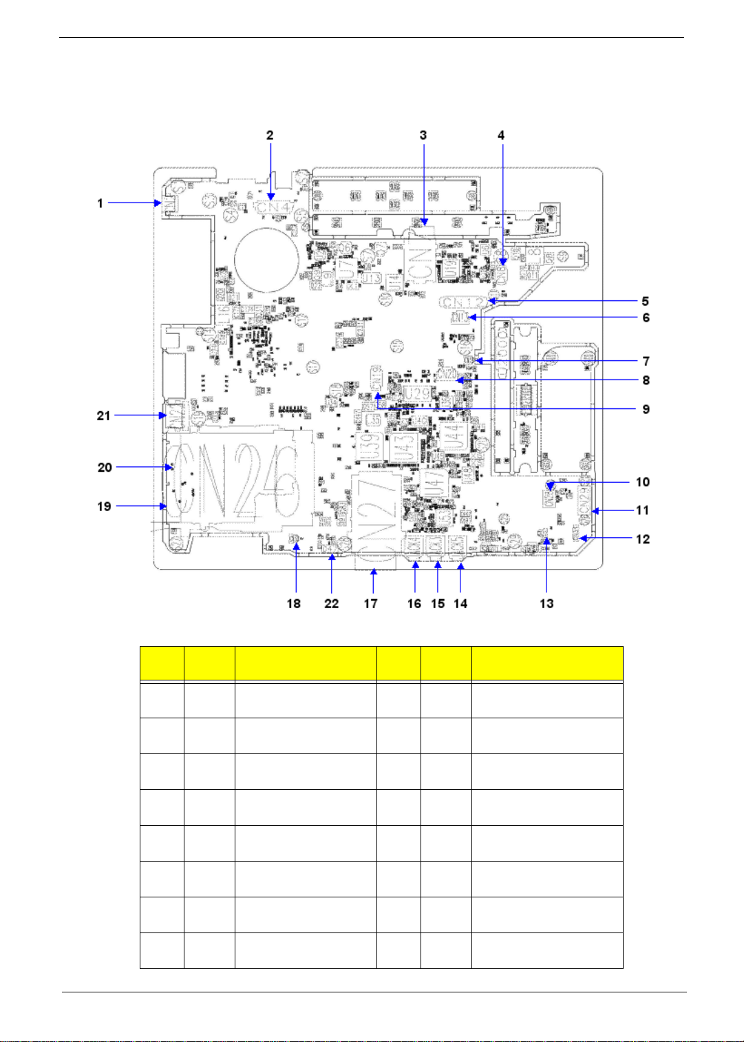
Mainboard Layout
Top View
Ite
m
1 CN2 S-Video 12 CN34Bluetooth Cable CNTR
2 CN4 LCM Cable CNTR 13 CN32Speaker Cable CNTR
3 CN7 3G Card CNTR 14 Jack5Headphone Jack
4 CN8 Hot Keyboard CNTR 15 Jack3Line-In Jack
5 CN12Keyboard FFC CNTR 16 Jack4MIC Jack
6 CN13Fine Track FFC
7 CN18MIC Cable CNTR 18 CN33Speaker CAble CNTR
8 CN20TouchPad FFC CNTR 19 CN24PCMCIA Socket
Chapter 1 5
Nam
e
Description
CNTR
Ite
m
17 CN275 in 1 Card Reader
Nam
e
Description
Socket

Ite
m
9 CN19SmartCard CAble
10 CN28MDC CNTR 21 CN22USB
11 CN29IO Board CNTR 22 D47 IR Receiver
Bottom View
Nam
e
Description
CNTR
Ite
m
20 CN26PCMCIA Socket
Nam
e
Description
Item Name Description
1 Jack500DC In Jack 11 U512 South Bridge
2 CN500 Serial Port 12 CN515W/LAN Card CNTR
3 CN501 Fan Cable CNTR 13 CN511ODD CNTR
4 CN508 1394 14 CN510HDD CNTR
6 Chapter 1
Ite
m
Name Description

Item Name Description
5 Jack501Ethernet jack and RJ11
Jack
6 U507 North Bridge 16 CN506RTC Battery CNTR
7 U505 CPU Socket 17 CN505MDC Cable CNTR
8 CN509 MDC Cable CNTR 18 CN504MainBoard and IO Board
9 CN512 DIMM Socket 19 C N 5 03Docking CNTR
10 CN513 DIMM Socket 20 CN502Battery CNTR
Ite
m
15 CN507Second Battery CNTR
Name Description
CNTR
Chapter 1 7

Your Acer Notebook tour
After knowing your computer features, let us show you around your new TravelMate 6492 computer.
Front View
# Item Description
1 Acer Crystal Eye Web camera for video communication (for selected
models).
2 Display screen Also called Liquid-Crystal Display (LCD), displays
computer output.
3 Acer Fine Touch
Keyboard
4 Acer Fine Track Touch-sensitive pointing device which functions like a
5 Acer Bio-Protection
fingerprint reader
6 Touchpad Touch-sensitive pointing device which functions like a
7 Status indicators Light-Emitting Diodes (LEDs) that light up to show the
8 Chapter 1
For entering data into your computer.
computer mouse when used together with the click
buttons.
The center button serves as Acer Bio-Protection
fingerprint reader supporting Acer FingerNav 4-way
control function. (for selected models).
computer mouse.
status of the computer's functions and components.
8 Click buttons (left, center
Note:
"Easy-launch buttons" on page 18
"Easy-launch buttons" on page 18
and right)
9 Palmrest Comfortable support area for your hands when you use
10 FineTrack buttons (left
and right)
11 Power button Turns the computer on and off.
12 Status indicators Light-Emitting Diodes (LEDs) that light up to show the
13 Easy-launch buttons Buttons for launching frequently used programs.
14 Microphone Internal microphone for sound recording.
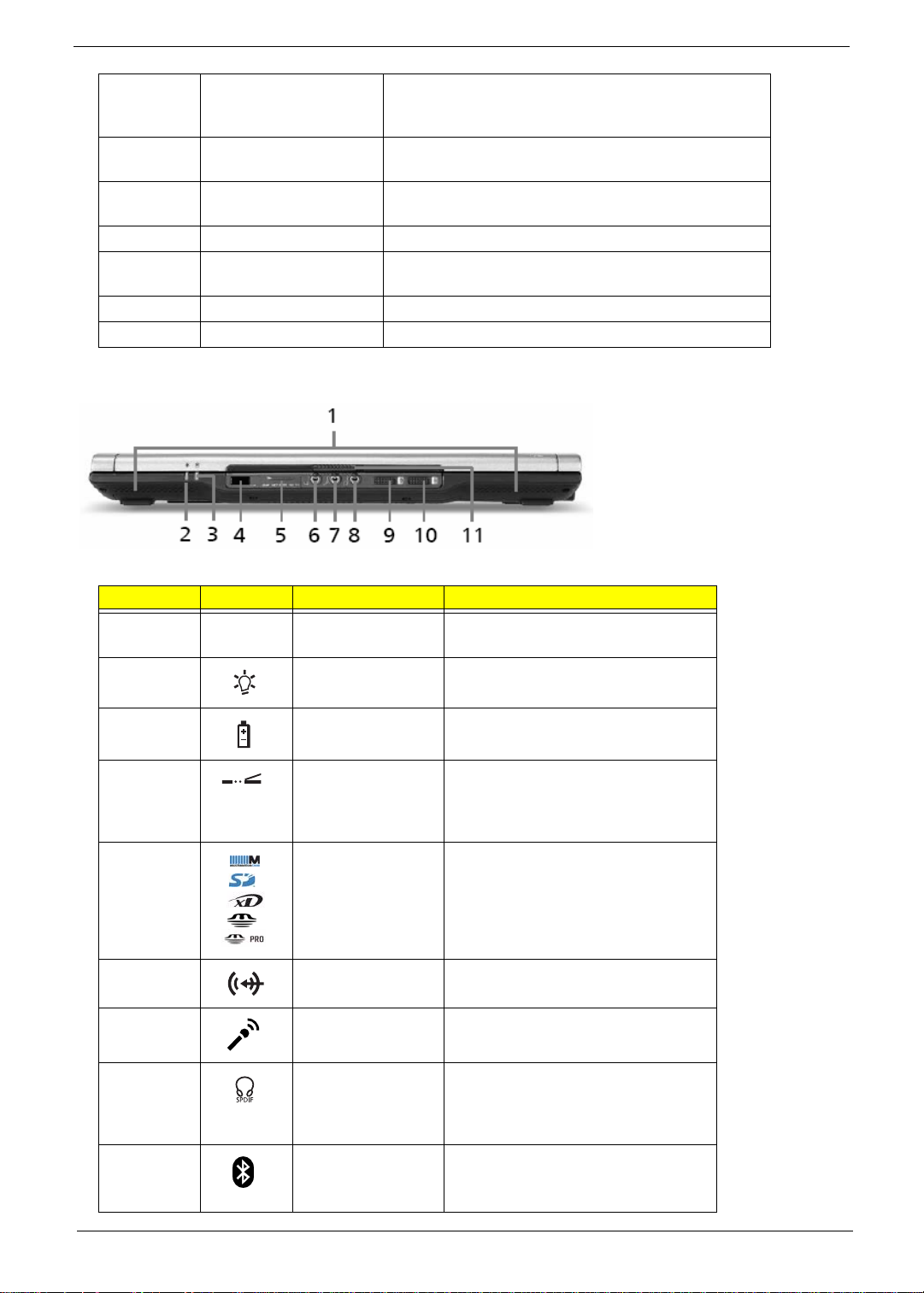
Closed Front View
The left and right buttons function like the left and right
mouse buttons; the center button serves as a 4-way
scroll button.
the computer.
Function like the left and right mouse buttons when
used together with the center-keyboard FineTrack.
status of the computer's functions and components.
# Icon Item Description
1 Speakers Left and right speakers deliver stereo
audio output.
2 Power indicator Indicates the computer’s power status.
3 Battery indicator Indicates the computer’s battery
status.
4 Infrared port/CIR
receiver
5 5-in-1 card reader Accepts Secure Digital (SD),
6 Line-in jack Accepts audio line-in devices (e.g.,
7 Microphone-in jack Accepts input from external
8 Headphones/
speaker/line-out
jack with S/PDIF
support
9
Bluetooth
communication
button/indicator
®
Interfaces with infrared devices (e.g,
infrared printer and IR-aware
computer)/Receives signals from a
remote control.
MultiMediaCard (MMC), Memory Stick
(MS), Memory Stick PRO (MS PRO),
xD-Picture Card (xD).
audio CD player, stereo walkman).
microphones.
Connects to audio line-out devices
(e.g., speakers, headphones).
Enables/disables the Bluetooth®
function. Indicates the status of
Bluetooth communication.
Chapter 1 9
10 Wireless
communication
button/indicator
11 Latch Locks and released the lid.
Enables/disables the wireless
function. Indicates the status of
wireless LAN communication.
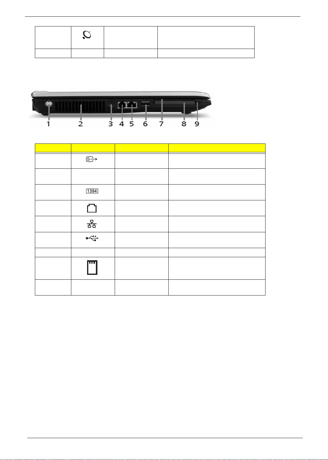
Left View
# Icon Item Description
1 S-video/TV-out
(NTSC/PAL) port
2 Ventilation slots Enable the computer to stay cool,
3 4-pin IEEE 1394
port
4 Modem (RJ-11) port Connects to a phone line.
Connects to a television or display
device with S-video input.
even after prolonged use.
Connects to IEEE 1394 devices.
5 Ethernet (RJ-45) Connects to an Ethernet 10/100/1000-
based network (for selected models).
6 USB 2.0 port Connects to USB 2.0 devices (e.g.,
USB mouse, USB camera).
7 SmartCard slot Accepts the TravelMate SmartCard
8 PC Card slot Accepts one Type II PC Card.
9 PC Card slot eject
button
Ejects the PC Card from the slot.
10 Chapter 1
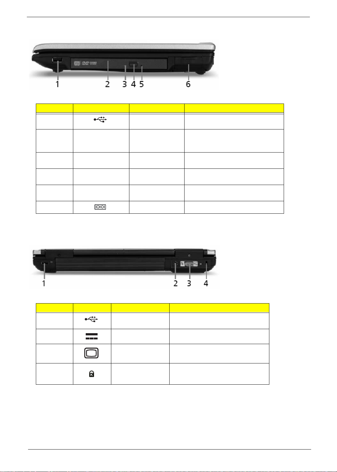
Right View
# Icon Item Description
1 USB 2.0 port Connect to USB 2.0 devices (e.g.,
USB mouse, USB camera).
2 Acer MediaBay
optical drive
3 Optical disk access
indicator
4 Optical drive eject
button
5 Emergency eject
hole
6 Serial port Connects to a serial device.
Internal optical drive; accepts CDs or
DVDs (slot-load or tray-load
depending on model).
Lights up when the optical drive is
active.
Ejects the optical disk from the drive.
Ejects the optical drive tray when the
computer is turned off.
Rear view
# Icon Item Description
1 USB 2.0 port Connect to USB 2.0 devices (e.g.,
USB mouse, USB camera).
2 DC-IN jack Connects to an AC adapter.
3 External display
(VGA) port
4 Kensington lock
slot
Connects to a display device (e.g.,
external monitor, LCD projector).
Connects to a Kensingtoncompatible computer security lock.
Chapter 1 11
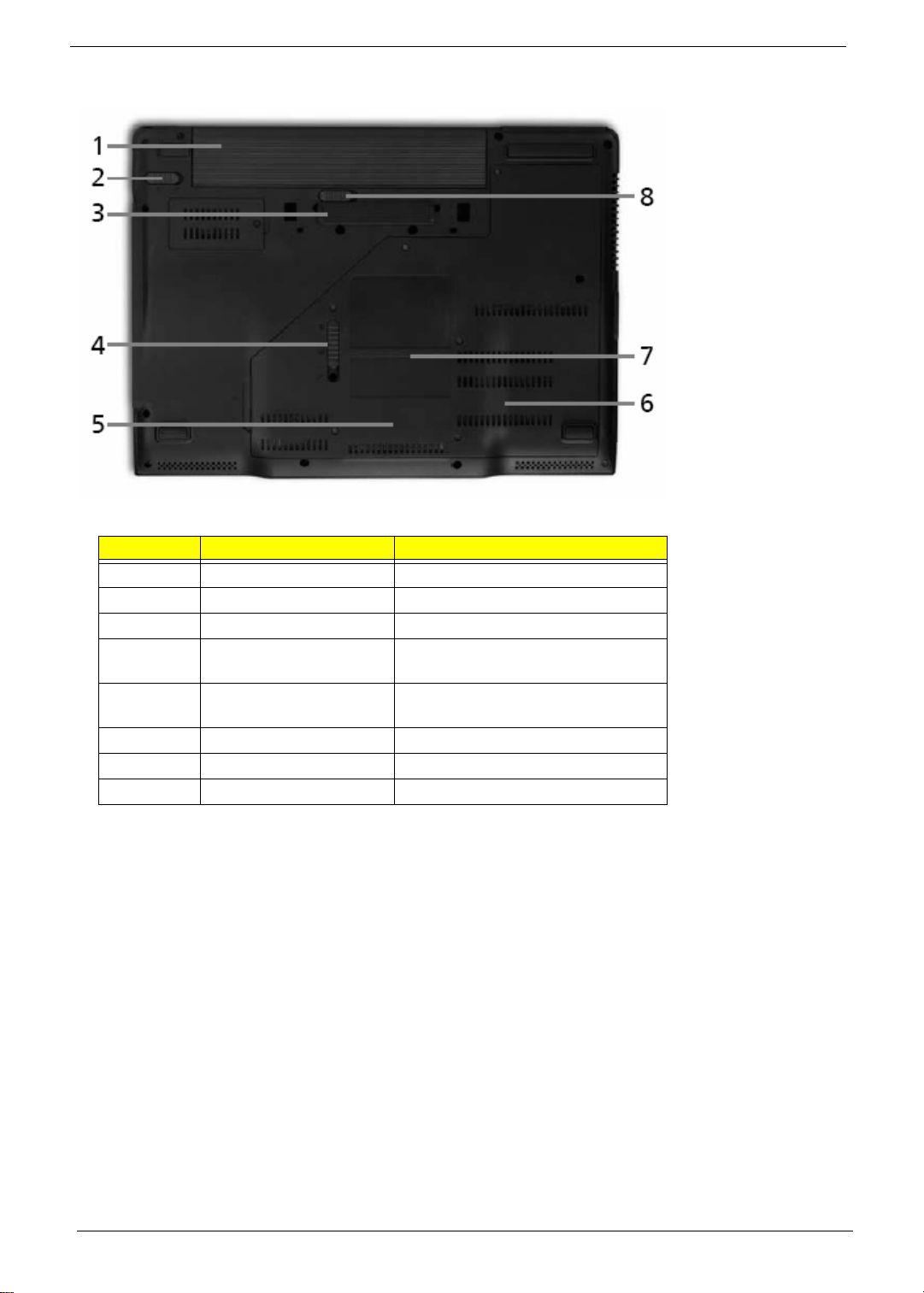
Base view
# Item Description
1 Battery bay Houses the computer’s battery pack.
2 Battery lock Locks the battery in position.
3 ezDock II/II+ connector Connects to the Acer ezDock II/II+.
4 Acer MediaBay release
latch
5 Hard disk bay Houses the computer’s hard disk
6 Memory compartment Houses the computer’s main memory.
7 Acer DASP Disk Anti-Shock Protection.
8 Battery latch Release the battery pack.
Lock or unlock the Acer MediaBay
device.
(secured with screws)
12 Chapter 1
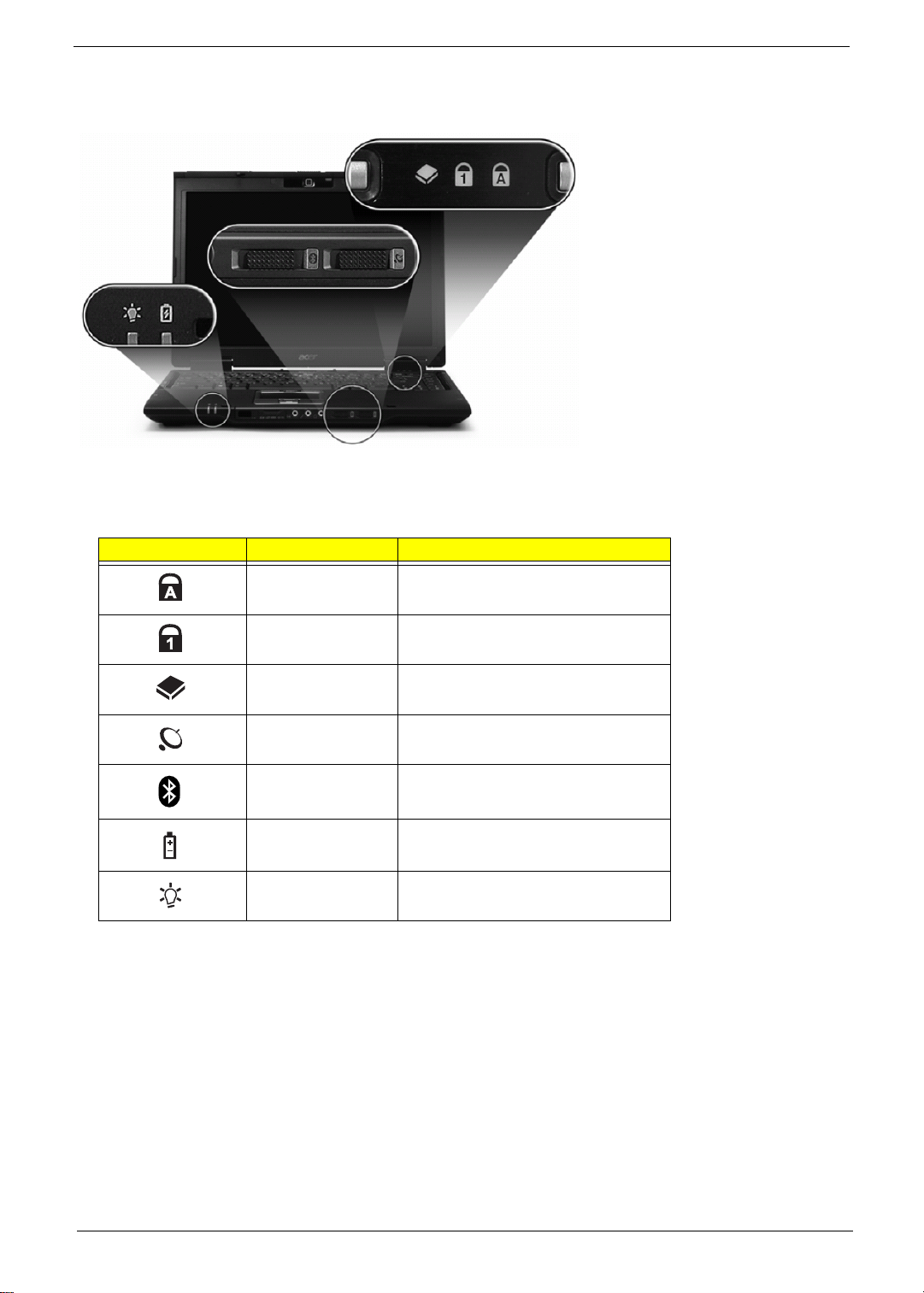
Indicators
The computer has several easy-to-read status indicators.
The front panel indicators are visible even when the computer cover is closed up.
Icon Function Description
Cap lock Lights when Cap Lock is activated
Num lock Lights when Num Lock is activated.
HDD Indicates when the hard disc or
optical drive is active.
Wireless LAN Indicates the status of wireless LAN
communication.
Bluetooth Indicates the status of Bluetooth
communication.
Battery Lights up when the battery is being
charged.
Power Lights up when the computer is on.
Note: 1. Charging: The light shows amber when the battery is charging. 2. Fully charged: The light shows
green when in AC mode.
Chapter 1 13
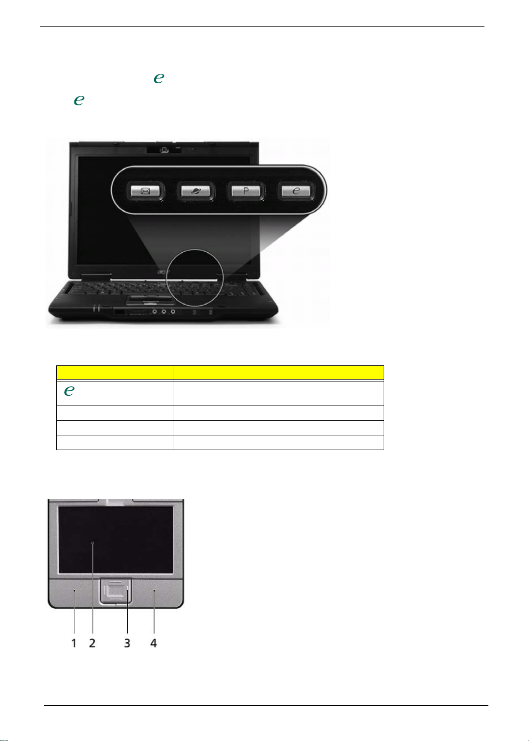
Easy-Launch Buttons
Located above the keyboard are four buttons. These buttons are called easy-launch buttons. They are: mail Web
browser, Empowering Key “ “and one user-programmable button.
Press “ “ to run the Acer Empowering Technology. The mail and Web browser buttons are pre-set to email and
Internet programs, but can be reset by users. To set the Web browser, mail and programmable buttons, run the
Acer Launch Manager.
Launch key Default application
Acer Empowering Technology (user-
programmable)
P User-programmable
Web browser Internet browser (user-programmable)
Mail Email application (user-programmable)
Touchpad Basics
The following teaches you how to use the touchpad:
• Move your finger across the touchpad (2) to move the cursor.
• Press the left (1) and right (4) buttons located beneath the touchpad to perform selection and execution
functions. These two buttons are similar to the left and right buttons on a mouse. T apping on the touchpad
14 Chapter 1
is the same as clicking the left button.
• Use the 4-way scroll (3) button to scroll up or down and move left or right a page. This button mimics your
cursor pressing on the right scroll bar of Windows applications.
Function
Left Button
(1)
Execute Click twice
quickly
Right Button
(4)
Main
touchpad (2)
Tap twice (at
the same
Center button (3)
speed as
doubleclicking the
mouse
button)
Select Click once Tap once
Drag Click and
hold, then use
finger on the
touchpad to
drag the
cursor.
Tap twice (at
the same
speed as
doubleclicking a
mouse
button); rest
your finger on
the touchpad
on the second
tap and drag
the cursor.
Access
Click once
context menu
Scroll Click and hold to move
up/down/left/right.
Note: When using the touchpad, keep it - and your infers - dry and clean. The touchpad is sensitive to finger
movements; hence, the lighter the touch, the better the response. Tapping too hard will not increase the
touchpad’s responsiveness.
Chapter 1 15
Using the Keyboard
The keyboard has full-sized keys and an embedded keypad, separate cursor keys, two Windows keys and twelve
function keys.
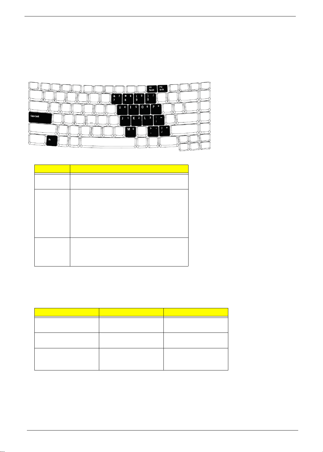
Lock Keys and embedded numeric keypad
The keyboard has three lock keys which you can toggle on and off.
Lock Key Description
Caps Lock When Caps Lock is on, all alphabetic characters
typed are in uppercase.
Num lock
<Fn>+<F11>
Scroll lock
<Fn>+<F12>
When Num Lock is on, the embedded keypad is
in numeric mode. The keys function as a
calculator (complete with the arithmetic
operators +, -, *, and /). Use this mode when
you need to do a lot of numeric data entry. A
better solution would be to connect an external
keypad.
When Scroll Lock is on, the screen moves one
line up or down when you press the up or down
arrow keys respectively. Scroll Lock does not
work with some applications.
The embedded numeric keypad functions like a desktop numeric keypad. It is indicated by small characters
located on the upper right corner of the keycaps. To simplify the keyboard legend, cursor-control key symbols are
not printed on the keys.
Desired Access Num Lock On Num Lock Off
Number keys on
embedded keypad
Cursor-control keys on
embedded keypad
Main keyboard keys Hold <Fn> while typing
16 Chapter 1
Type numbers in a
normal manner.
Hold <Shift> while using
cursor-control keys.
letters on embedded
keypad.
Hold <Fn> while using
cursor-control keys.
Type the letters in a
normal manner.
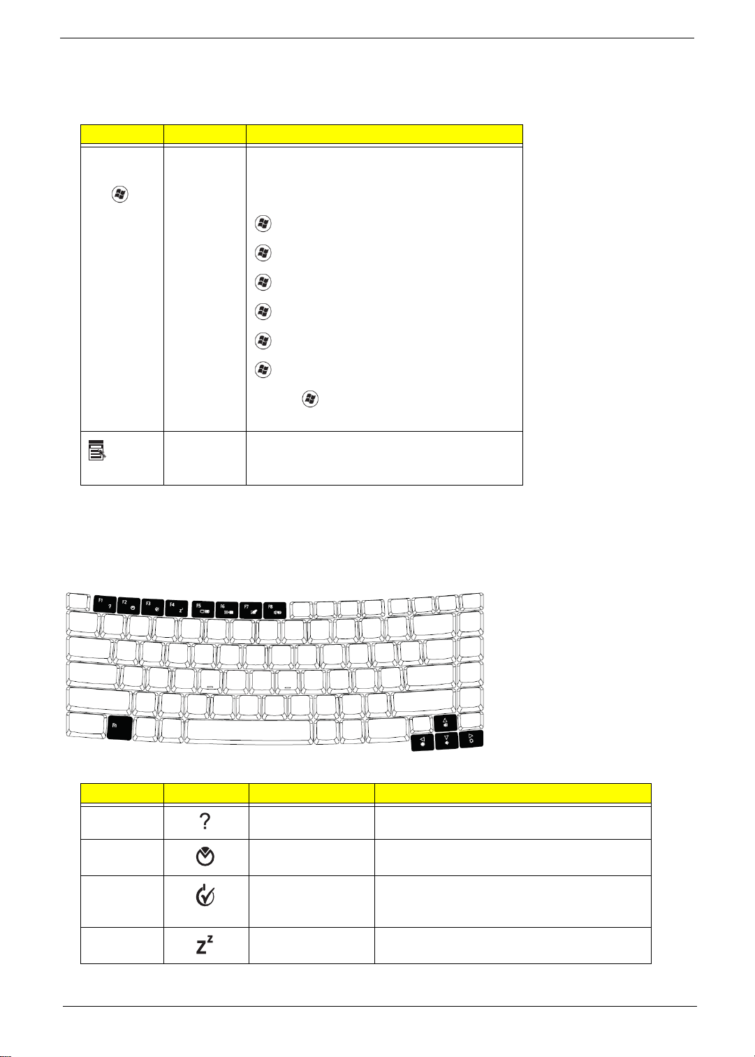
Windows Keys
The keyboard has two keys that perform Windows-specific functions.
Key Icon Description
Windows
key
Applicat
ion key
Pressed alone, this key has the same effect as
clicking on the Windows Start button; it launches
the Start menu. It can also be used with other
keys to provide a variety of function:
+ <Tab> Activates next taskbar button.
+ <E> Opens the My Computer window
+ <F1> Opens Help and Support.
+ <F> Opens the Find: All Files dialog box.
+ <R> Opens the Run dialog box.
+ M Minimizes all windows.
<Shift>+ + <M> Undoes the minimize all
windows action.
This key has the same effect as clicking the right
mouse button; it opens the application’s context
menu.
Hot Keys
The computer employs hotkeys or key combinations to access most of the computer’s controls like screen
brightness, volume output and the BIOS utility.
To activate hot keys, press and hold the <Fn> key before pressing the other key in the hotkey combination.
Hot Key Icon Function Description
<Fn>+<F1> Hot key help Displays help on hot keys.
<Fn>+<F2> Acer eSetting Launches the Acer eSettings in Acer eManager.
<Fn>+<F3> Acer
ePowerManagement
<Fn>+<F4> Sleep Puts the computer in Sleep mode.
Launches the Acer ePowerManagement in Acer
Empowering Technology. See “Acer
Empowering Technology” on page 19.
Chapter 1 17
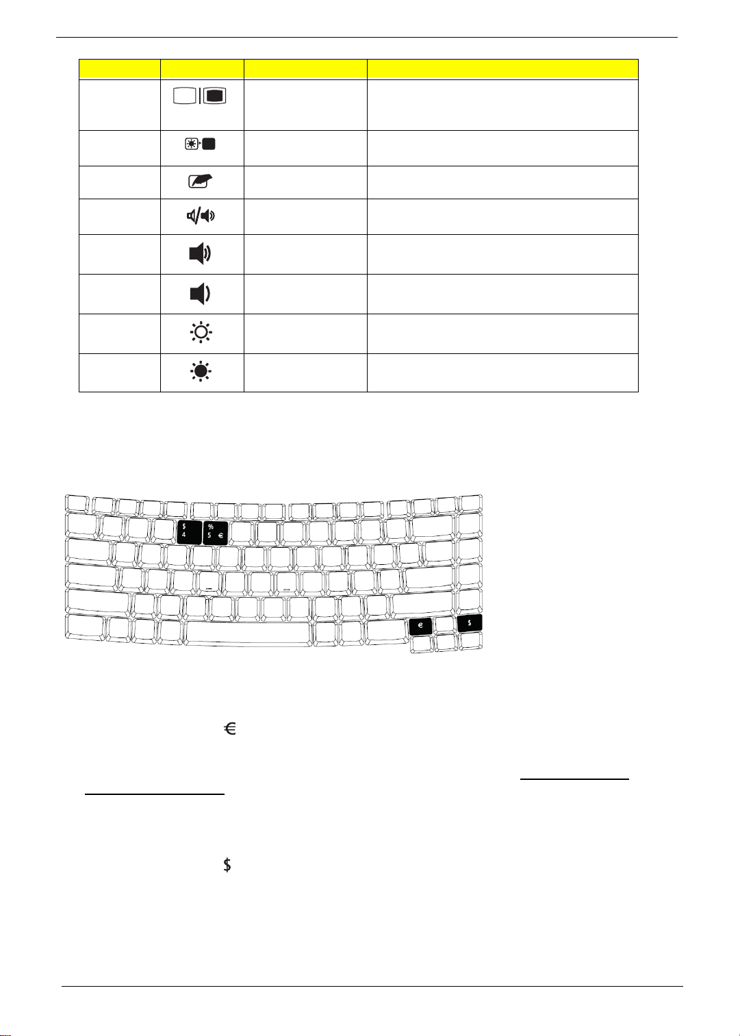
Hot Key Icon Function Description
<Fn>+<F5> Display toggle Switches display output between the display
screen, external monitor (if connected) and
both.
<Fn>+<F6> Screen blank Turns the display screen backlight off to save
power. Press any key to return.
<Fn>+<F7> Touchpad toggle Turns the internal touchpad on and off.
<Fn>+<F8> Speaker toggle Turns the speakers on and off.
<Fn>+<w> Volume up Increases the speaker volume.
<Fn>+<y> Volume down Decreases the speaker volume.
<Fn>+<-x> Brightness up Increases the screen brightness.
<Fn>+<z> Brightness down Decreases the screen brightness
Special Key
You can locate the Euro symbol and US dollar sign at the upper-center and/or bottom-right of your keyboard. To
type:
The Euro symbol
1. Open a text editor or word processor.
2. Either directly press the <> symbol at the bottom-right of the keyboard, or hold <Alt Gr> and then press
the<5> symbol at the upper-center of the keyboard.
Note: Some fonts and software do not support the Euro symbol. Please refer to www.microsoft.com/
typography/faq/faq12.htm for more information.
The US dollar sign
1. Open a text editor or word processor.
2. Either directly press the <> key at the bottom-right of the keyboard, or hold <Shift> and then press the <4>
key at the upper-center of the keyboard.
Note: This function varies by the operating system version.
18 Chapter 1

Acer Empowering Technology
Acer’s innovative Empowering Technology makes it easy for you to access frequently used functions and manage
your new Acer notebook. It features the following handy utilities:
q Acer eDataSecurity Management pro tects data with passwords and advanced encryption algorithms.
q Acer eLock Management limits access to external storage media.
q Acer ePerformance Management improves system performance by optimizing disk space, memory and
registry settings.
q Acer eRecovery Management backs up/recovers data flexibly, reliably and completely.
q Acer eSettings Management accesses system information and adjusts settings easily.
q Acer ePower Management extends battery power via versatile usage profiles.
q Acer ePresentation Management connects to a projector and adjusts display settings conveniently.
For more information, press the < > key to launch the Empowering Technolo gy menu, then click on the
appropriate utility and select the Help function.
Acer eDataSecurity Management
Acer eDataSecurity Management is handy file encryption utility that protects your files from being accessed by
unauthorized persons. It is conveniently integrated with Windows explorer as a shell extension for quick and easy
data encryption/decryption and also supports on-the-fly file encryption for MSN Messenger and Microsoft Outlook.
Chapter 1 19
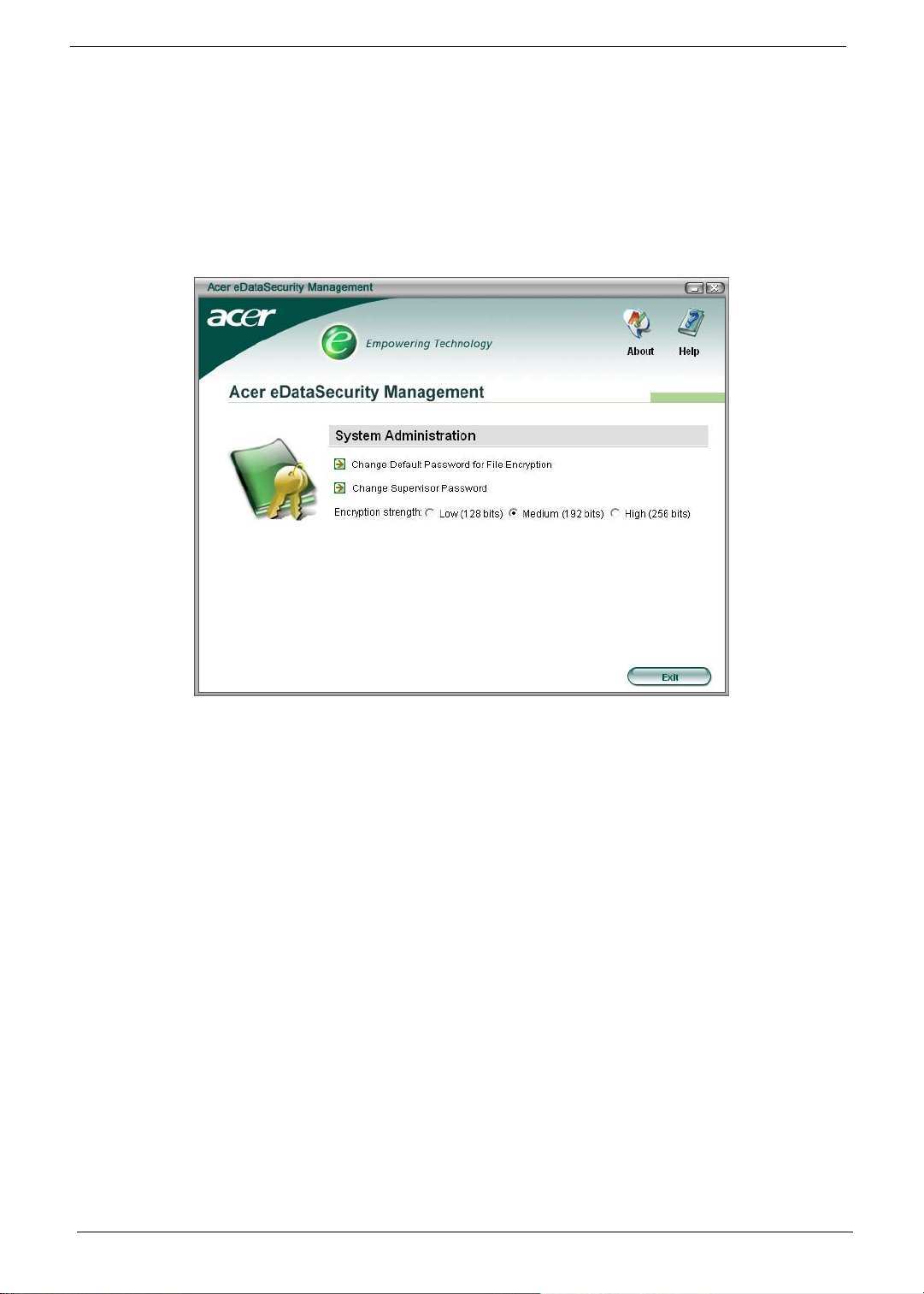
There are two passwords that can be used to encrypt/decrypt a file; the supervisor password and the file-specific
password. The supervisor password is a “master” password that can decrypt any file on your system; the filespecific password will be used to encrypt files by default, or you can choose to enter your own file-specific
password when encrypting a file.
Note: The password used encrypt a file is the unique key that the system needs to decrypt it. If you lose the
password, the supervisor password is the only other key capable of decrypting the file. If you lose both
passwords, there will be no way to decrypt your encrypted file! Be sure to safeguard all related passwords!
20 Chapter 1
 Loading...