

Acer TRAVELMATE 510 Service Manual

TravelMate 510 Notebook
Service Guide
Service guide files and updates are available
on the AIPG/CSD web; for more information,
please refer to http://csd.acer.com.tw
PART No: 49.45C01.001.
DOC No: SG370...................................................PRINT IN TAIWAN

Copyright
Copyright © 1999 by Acer Incorporated. All rights reserved. No part of this
publication m ay be reproduced, transmitted, transcribed, stored in a retrieval
system, or translated i nto any languag e or computer l anguage, in any form or
by any means , ele ctroni c, mech ani cal, magneti c, opt ical , chem ical , manual or
otherwise, with out the prior written permiss ion of Acer Incorporated.
Disclaimer
Acer Incorporated makes no representations or warranties, either expressed
or implied, with respect to the contents hereof and specifically disclaims any
warranties of merchantability or fitness for any particular purpose. Any Acer
Incorporat ed software described in this manual is sold or licensed "as is".
Should the progr ams prove def ect ive f ollowing t hei r purcha se, the bu yer (and
not Acer Incorporated, its distributor, or its dealer) assumes the entire cost of
all necessary servicing, repair, and any incidental or consequential damages
resultin g from any defect in t he softwar e. F urther, Acer Incor porat ed r eserve s
the right to revise this publication and to make cha nges from time to time in
the contents hereof without obligation of Acer Incorporated to notify any
person of such revision or changes.
Acer is a registered trademark of Acer Incorporated.
Intel is a regist ered trademark of Intel Corporation.
Pentium is a trademar k of Intel Corporation.
Other brand and product names are trademarks and/or registered
trademarks of th eir respective holders.
II

Conventions
The following conventions are used in this manual:
Screen messages
Note
Warning
Caution
Important
Denotes actual messages that appear on-
screen.
Gives bits and pieces of additional information
related to the current topic.
Alerts you to any damage that might result from
doing or not doing specific actions.
Gives precautionary measure s to avoid possible
hardware or softwar e problems.
Reminds you to do specific actions relevant to the
accomplishment of procedure s .
III

Preface
Before using this information and the product it supports, please read the following general inf ormation!
1 This Service Guide provides you with all technical information relating to
the BASIC CONFIGURATION deci ded for Acer 's "gl obal" produc t off ering.
To better fit local market requirements and enhance product competitiveness, your regional office M AY have decided to extend the functionality of
a machine (e.g. add-on card, modem, or extra memory capability). These
LOCALIZED FEATURES will NOT be covered in this generic service
guide. In such cases, please contact your regional offices or the responsible personnel/ channel to provide you with furt her technical details.
2. Please note WHEN ORDERING FRU PARTS, that you should check the
most up-to-date information available on your regional web or channel. If,
for whatever reason, a part number change is made, it will not be noted in
the printed Service Guide. For ACER-AUTHORIZED SERVICE
PROVIDERS, your Acer o ffice may have a DI FFERENT pa rt number code
to those given i n the FRU list of this print ed Servic e Guide . You MUST use
the list provided by your regional Acer office to order FRU parts for repair
and service of cus tomer machines.
IV

Table of Contents
Chapter 1 System Introductions 1
Basic Operation . . . . . . . . . . . . . . . . . . . . . . . . . . . . . . .4
Indicators. . . . . . . . . . . . . . . . . . . . . . . . . . . . . . . . . .4
Keyboard . . . . . . . . . . . . . . . . . . . . . . . . . . . . . . . . . . . .5
Special Keys . . . . . . . . . . . . . . . . . . . . . . . . . . . . . . .5
Keyboard Ergonomics. . . . . . . . . . . . . . . . . . . . . . .10
Touchpad . . . . . . . . . . . . . . . . . . . . . . . . . . . . . . . . . . .11
Hardware Configuration and Specification . . . . . . . . . .13
Processor . . . . . . . . . . . . . . . . . . . . . . . . . . . . . . . .15
Power Management . . . . . . . . . . . . . . . . . . . . . . . . . . .26
Power Management Modes . . . . . . . . . . . . . . . . . .26
Advanced Power Management . . . . . . . . . . . . . . . . 29
Advanced Configuration and Power Interface. . . . .29
Chapter 2 Software Utilities 31
BIOS Setup Utility. . . . . . . . . . . . . . . . . . . . . . . . . . . . .31
System Information . . . . . . . . . . . . . . . . . . . . . . . . .32
Basic System Configuration . . . . . . . . . . . . . . . . . .33
Startup Configuration . . . . . . . . . . . . . . . . . . . . . . .34
Onboard Devices Configuration . . . . . . . . . . . . . . .35
System Security . . . . . . . . . . . . . . . . . . . . . . . . . . .37
Power Management . . . . . . . . . . . . . . . . . . . . . . . .40
Load Default Settings . . . . . . . . . . . . . . . . . . . . . . .41
AFlash Ut ilit y. . . . . . . . . . . . . . . . . . . . . . . . . . . . . . . . .42
Executing AFlash . . . . . . . . . . . . . . . . . . . . . . . . . .42
Quick Way to Execute AFlash. . . . . . . . . . . . . . . . .43
System Utility Diskette . . . . . . . . . . . . . . . . . . . . . . . . .44
Set LCD Panel ID . . . . . . . . . . . . . . . . . . . . . . . . . .44
Set Thermal Sensor Threshold . . . . . . . . . . . . . . . .45
System Diagnostic Diskette . . . . . . . . . . . . . . . . . . . . . 46
Running PQA Diagnostics Program.. . . . . . . . . . . .47
Chapter 3 R emoval and Repla cement 51
General Information . . . . . . . . . . . . . . . . . . . . . . . . . . .52
Before You Begin . . . . . . . . . . . . . . . . . . . . . . . . . .52
Connector Types. . . . . . . . . . . . . . . . . . . . . . . . . . .52
Disassembly Procedure Flowchart. . . . . . . . . . . . . . . .53
Removing the Battery Pack. . . . . . . . . . . . . . . . . . .55
I

Table of Contents
Removing the DIMM. . . . . . . . . . . . . . . . . . . . . . . . 55
Removing the Modem Board . . . . . . . . . . . . . . . . . 5 6
Removing the Keyboard. . . . . . . . . . . . . . . . . . . . . 57
Removing the LCD Module . . . . . . . . . . . . . . . . . . 59
Disassembling the LCD. . . . . . . . . . . . . . . . . . . . . . . . 61
Disassembling the Main Unit. . . . . . . . . . . . . . . . . . . . 64
Removing the Heat Sink and CPU EMI Shield. . . . 64
Removing the Hard Disk Drive. . . . . . . . . . . . . . . . 65
Removing the Upper Case. . . . . . . . . . . . . . . . . . . 65
Removing the Touchpad . . . . . . . . . . . . . . . . . . . . 66
Disassembling the Lower Case . . . . . . . . . . . . . . . 68
Removing the CD-ROM/ Diskette Drive Module . . 69
Removing the Speakers. . . . . . . . . . . . . . . . . . . . . 7 1
Removing the DC-DC/ Charger Board. . . . . . . . . . 72
Removing the FIR module . . . . . . . . . . . . . . . . . . . 74
Removing the System Board . . . . . . . . . . . . . . . . . 75
Removing the PCMCIA Card . . . . . . . . . . . . . . . . . 76
Chapter 4 Troubleshooting 79
System Check Procedures . . . . . . . . . . . . . . . . . . . . . 80
Diskette Drive Check . . . . . . . . . . . . . . . . . . . . . . . 80
CD-ROM Drive Check . . . . . . . . . . . . . . . . . . . . . . 80
Keyboard or Auxiliary Input Device Check. . . . . . . 81
Memory Check. . . . . . . . . . . . . . . . . . . . . . . . . . . . 81
Power System Check. . . . . . . . . . . . . . . . . . . . . . . 81
Touchpad Check . . . . . . . . . . . . . . . . . . . . . . . . . . 83
Error Symptom-to-FRU Index . . . . . . . . . . . . . . . . . . . 8 4
Intermittent Problems. . . . . . . . . . . . . . . . . . . . . . . 9 2
Undetermined Problems. . . . . . . . . . . . . . . . . . . . . 92
Chapter 5 Jumper and Connector Information 95
Top View . . . . . . . . . . . . . . . . . . . . . . . . . . . . . . . . . . . 95
Bottom View . . . . . . . . . . . . . . . . . . . . . . . . . . . . . . . . 97
Chapter 6 FRU (Field Replaceable Unit) List 99
Exploded Diagram. . . . . . . . . . . . . . . . . . . . . . . . . . . 115
II

Table of Contents
Appendix A Model Number and Configurations117
Appendix B Test Compatible Components List119
Appendix C Online Support Information 125
Index 127
III

IV
Chapter 1
System Introductions
This computer was designed with the user in mind. Here are just a few of its
many features:
Performa nc e
Intel® Celeron™ proc essor with 128 KB level 2 cache
64-bit ma in m em or y
Large LCD display and AGP vid eo with 256-bit graphics acceleration
Internal CD-ROM drive or DVD-ROM drive
Internal 3.5-inch floppy drive
High-capacity, Enhanced-IDE hard disk
Lithium-ion battery pack
Power management sys tem wit h standby and hibernation power saving
modes
Multimedia
ISA-based 16- bit h igh-f ideli ty s tereo audi o wit h 3-D so und and wa vetabl e
synthesizer
Play-now audio capability
Built-in dual speakers
Compact disc player control feature
Ultra-slim, high-speed CD-ROM drive or DVD-ROM drive
1
Connectivity
High-speed fax/data modem port (available in select countries)
USB (Universal Serial Bus) port
Human-centric Design and Ergonomics
All-in-one design (CD-ROM or DVD-ROM, FDD, HDD)
Lightweight and slim
Sleek, smooth and st ylish design
Full-sized keyboard
Wide and curved palm rest
Ergonomically-centered touchpad pointing device
1
Subject to local configuration
Chapter 1 1

CD or DVD player control
Expansi on
CardBus PC card (formerly PCMCIA) slots (two type II/I or one type III),
upper sort with ZV (Zoomed Video) port support
Port replicator option for one-step connect/disconnect from peripherals
Upgradeable memory and hard disk
2
Display
The large graphics display offers excellent viewing, excellent display quality
and high performance desktop graphics. The comput er supports two
differ ent display configurations — High Performance Addressing (HPA) or
Thin-Film Transistor (TFT).
Video Perfor m anc e
AGP video with 256-bit graphics acceleration and 2.5 MB video memory
boost video performance.
Simultaneous Display
The computer’s large display and multimedia capabilities are great for giving
presentati ons. If you prefer, you can also connect an external moni tor when
giving presentations. This computer suppor ts simultaneous LCD and CRT
display. Simultaneous di splay allows you to control the presentation from
your computer and at the same time face your audien ce. You can also
connect other out put display devi ce s such as LCD projection panels for l argeaudience presentations.
Dural Display
The computer’s unique gra phics chi p takes advant age of Windows 98’ s multi display capability, allowing you to extend your desktop to an external display
device, such as an external monitor or project or. With this feature enabled,
you can move program windows to/from the computer LCD and the exteranl
monitor.
Power Management
The power management system incorporates an “automatic LCD dim”
feature that automatically dims the LCD when the computer is powered by a
battery pack to conserve battery power.
2
Only the upp er sl ot su pp or t s Zo om ed Vid eo
2 System Introductions

Opening and Closing the Display
To open the display, slide the display cover latch to the lef t and l ift up the
cover . Then til t it to a comfortab le viewing posi t ion. The comput er employ s a
microswitc h that turns off the display ( and enters standby mode) to conserve
power when you close the display cover and turns it back on when you ope n
the display cover.
Note:
If an external monitor is connected, the computer turns off the
display (but does not ent er standby mode) when you close the
display cover.
To close the display cover, fold i t down gently until the display cov er l atch
clicks int o place.
Caution:
Also, do not place any object on top of the computer when the display is
closed.
To avoid damaging the display, do not slam it when you close it.
Chapter 1 3

Basic Oper ati on
Indicators
The computer has si x easy- t o-read status indi cat ors ( LEDs) under the d is play
screen.
The Power and Standby indi cators are visible even when you close the
display cover so you can see the status of the computer while the cover is
closed.
# Icon Function Description
1 Power Ligh ts when the c omputer is on.
Blinks when a battery-low condition occurs.
2 Standby Light s when the computer enters Standby
mode.
3 Media
Activity
4 Battery
Charge
5 Caps Lock Lights when Caps Lock is activat ed
6Num Lock
(Fn-F11)
Lights when the floppy drive, hard disk or
CD-ROM drive or DVD-ROM drive is
active.
Lights when the battery is bein g charged.
Lights when Numeric Lock is activated
4 System Introductions

Keyboard
The keyboard has full-sized ke ys and an embedded keyp ad, separate cursor
keys, two Windows keys and twelve function keys.
Special Keys
Lock Keys
The keyboard has three lock keys which you can toggle on and off.
Lock Key Description
Caps Lock When Caps Lock is on, all alphabetic characters typed are in
uppercase.
Num Lock
(Fn-F11)
Scroll Lock
(Fn-F12)
When Num Lock is on, the embedded keypad is in numeric
mode. The keys function as a calculator (complete with the
arithmetic operators +, -, *, and /). Use this mode when you
need to d o a lot of numeric data entry. A better solution would
be to conn ect an exte rnal keypad.
When Scroll Lock is on, the screen moves one line up or down
when you press ↑ or ↓ respectively. Scroll Lock does not work
with some applications.
Chapter 1 5

Embedded Numeric Keypad
The embedded numeric keypad functions like a desktop num eri c keypad. It
is indicated by sm all characters located on the upper right corner of the
keycaps. To simplify the key boar d lege nd, cursor -c ontrol key symbol s are not
printed on the keys.
Desired Access Num Lock On Num Lock Off
Number keys on
embedded keypad
Cursor-control keys on
embedded keypad
Main keyboard keys Hold Fn while typing letters
Type numbers in a norma l
manner.
Hold Shift while using
cursor-control keys.
on embedded keypad.
Hold Fn while
using cursorcontr ol ke y s.
Type the letters in
a normal manner.
Note:
If an external keyboard or keypad is connected to the comput er,
the NumLock feature aut om atically shifts from the int ernal
keyboard to the external keyboard or keypad.
6 System Introductions

Windows Keys
The keyboard has two keys that perform Windows-speci fic functions.
Key Description
Windows logo key Start button. Combinations with this key perform
Application key
(Fn-Application key)
special functions. Below are a few examples:
+ Tab (Activates next Taskbar button)
+ E (Explores My Computer)
+ F (Finds a Document)
+ M (Minim izes All)
Shift + + M (Undoe s Minimize Al l)
+ R (Displays the Run dialog box)
Opens the application’s context menu (same as rightclick).
The Euro Symbol
If your keyboar d is i n any of the following languages -- United StatesInternational, United Kingdom, French , German, Italian, Spanish,
Portuguese, Dani sh, Swiss German, Swiss French, Czech , Bel gian,
Norwegian, Hungarian, Turkish, Swedish or Finnish -- you can type the Euro
symbol on your keyboard.
Note:
Important! (for US keyboard users): The keyboard type is set
when you first set up Windows. For the Euro symbol to work, the
keyboard type has to be set to United States-International.
Chapter 1 7

To verify the keyboard type:
1. Click on
Start, Settings, Control Panel
.
2. Double-click on Keyboard.
3. Click on the Language tab.
4. V eri fy that the ke yboard t ype u sed for "En Engl ish (Uni ted St at es)" is s et to
United States-International.
5. If not, select and click on Properties; then select Unit ed S tates-
Intern atio n a l and click on OK.
6. Click on OK.
To type the Euro symbol:
1. Locate the Euro symbol on your keyboard.
2. Open a text editor or word processor.
3. Hold Alt Gr and press the Euro symbol.
The Alt Gr is only used together with the Euro symbol. Some
Note:
fonts and software do not support the Euro symbol. Please refer
to http://www.microsoft.com/typography/faq/faq12.htm for
more information .
Hot Keys
The computer empl oys hot keys or key combinations to access most of the
computer’s controls like screen contrast and brightness, volume output and
the BIOS setup utility.
Hot Key Icon Function Description
Fn-F1 Hotkey help Displays a list of the hotkeys and
their functions.
Fn-F2 Setup Accesses the notebook
configuration ut ility. .
8 System Introductions

Hot Key Icon Function Description
Fn-F3 Standby Puts the computer in Standby
mode. Pres s any key to ret urn.
See “Sy st em St an db y Mode” to
learn more about Standby mode.
Fn-F4 Hibernation Puts the computer in Hibernation
mode (if Sleep Manager, the
hibernation utility, is installed, valid
and enab led). Press the power
switch to resume.
Otherwise, the computer issues a
warnign beep and continues
operation. See "Hibernation
Mode" for more about Hibernation
mode.
Fn-F5 Display toggle Switches display output between
Fn-F6 Screen blank T urns the display screen backlight
Fn-F7 Touchpad on/off Turns the internal touchpad on
Fn-F8 Speaker on/off Turns the speakers on and off;
the display screen, external
monit or (if co nnected) an d both
the display screen and external
monitor.
off to save power. Press any key
to return.
and of f.
When you connect an external
PS/2 mouse, the computer
automatically disables the
touchpad.
mutes the sound.
Fn-
Fn-
Fn-
Fn-
↑
↓
→
←
Contrast up Increases the screen contrast
Contrast down Decreases the screen contrast
Brightness up Increases the screen brightness.
Brightness
down
(available only for models with
HPA displays).
(available only for models with
HPA displays).
Decreases the screen brightn ess.
Chapter 1 9

Activating Hotkeys
When activating hotkeys, press and hold the f irst key Fn before pressing t he
other key in the hotkey combination.
Keyboard Ergo nomics
Located below the keyboard, the wide and curved palm rest is ergonomically
designed to provi de you with a very comfortable place to rest your hands
while you type.
10 System Introduct ions

T ouchpad
The built-in touchpad is a PS/2-compatible point ing device that senses
movement on its surface . This mean s the curs or respon ds as you move your
finger on the surface of the touchpad. The central location on the palm rest
provides optimum comfort and support.
Note:
When you connect an external PS/2 mouse, the computer
automatically disables the internal touchpad.
Chapter 1 1 1

Touchpad Basics
The following items teach you how to use the touchpad:
1. Move your finger across the touchpad to move the cursor.
2. Press the left and ri ght buttons located on the edge of the touc hpad to do
selection and execution function s. These two buttons are similar to the left
and right buttons on a m ouse. Tapping on the touchpad produces similar
results.
Function Left Button Right Button Tap
Execute Click twice
quickly
Select Click once Tap once
Drag Click an d hold,
then use finger
to drag the
cursor on the
touchpad
Access
context
menu
Note:
Keep your fingers dr y and clean when using the touchpad. Also
Click o nce
keep the touchpad dry and clean. The touchpad is sensitive to
finger movements. Hence, the lighter the touch, the better the
response. Tapping too hard wil l not increase the touchpad’s
responsiveness.
T ap tw ice (at the sa me speed
as doub le -cl ic ki ng the mo us e
butto n)
T ap tw ice (at the sa me speed
as doub le -cl ic ki ng the mo us e
button) and hold finger to the
touchpad on the second tap
to drag the cursor
12 System Introduct ions

Hardware Configuration and Specification
Memory Address Map
Memory Address Size Function
00000000-0009FFFF 640 KB Base memory
000A0000-000BFFFF 128 KB Video memory
000C0000-000CBFFF 40 KB Video BIOS
000E0000-000FFFFF 128 KB System BIOS
001000 00 -t o p lim i ted
040000 00 -0 40 00 FFF
040010 00 -0 40 01 FFF
801000 00 -801000F F
80500000-805FFF FF
808000 00 -8 0B F FFF F
810000 00 -81FFFF FF
821000 00 -8 21 00 FFF
FFFF0000-FFFFFFFF 64 KB System board extension for
-4 KB
4 KB
256 B
1 MB
3 MB
16 MB
4 MB
Interrupt Channe l Assi gnm ent
Interrupt Channe l Function
NMI System errors
IRQ0 System timer
IRQ1 Keyboard
IRQ2 Cascade
IRQ3 FIR or COM2
IRQ4 COM1
IRQ5 Audio or LPT2 (optio nal)
IRQ6 Floppy
IRQ7 LPT1
IRQ8 Real time clock
IRQ9 Card bus / ACPI or Modem/ VGA
IRQ10 USB
IRQ11 Free or COM1
IRQ12 PS2 po inting devi ce
IRQ13 Numeric data processor
IRQ14 1st EIDE device (hard disk)
IRQ15 2nd EIDE device (CD-ROM drive)
Extended (DIMM) memory
PCMCIA controller (slot 1)
PCMCIA controller (slot 2)
Lucent Win Modem
NetMagic VGA
Neomagic VGA
PnP BIOS
Chapter 1 13

DMA Channel Assignment
DMA Channel Function
DRQ0 Audio(optional)
DRQ1 ECP or Audio(optional)
DRQ2 Floppy
DRQ3 ECP(optional)
DRQ4 DMA controller
DRQ5 Not used
DRQ6 Not used
DRQ7 Not used
I/O Address Map
I/O Address Function
000-00F DMA controller-1
020-021 Interrupt controller-1
040-043 Timer 1
060, 064 Keyboard controller 8742 chip select
061 System speaker out
040B DMA controller-1
061 System speaker
070-071 Real-time clo ck and NMI mask
080-08F DMA page register
0A0-0A1 Interrupt controller-2
0C0-0DF DMA controller-2
0F0-0FF Numeric data processor
120-13F, 180-18F Power ma n ag em ent controller
170-177 2nd EIDE device (CD-ROM) select
1F0-1F7 1st EIDE device (hard drive) select
220-22F Audio
240-24F Audio(optional)
278-27F Parallel port 3
2E8-2E F LT Win modem or COM4 (optional)
2F8-2FF COM2 or LT Win modem(optional)
378, 37A Parallel port 2
3BC-3BE paraller port 1
14 System Introduct ions

I/O Address Map
I/O Address Function
3B0-3B B, 3C 0 - 3DF Video Con tro ller
3F0h-3F7 Standa r d Flo pp y D is k Cont ro ll er
3E8-3EF COM3 or LT Win modem(optional)
3F0-3F7 Floppy disk controller
3F8-3FF COM1 or LT Win modem(optional)
480-48F, 4D6 DMA contr o ll er- 1
4D0-4D1, CF8-CFF PCI configuration register
Processor
Item Specification
CPU ty pe Intel Mobile Celeron-300
MHz processor -- Intel
Pentium architecture,
64 bit data bus, 16K-Byte
code cache, 16 K-Bytes
write back data, cache, with
MMX technology
CPU pack age BGA package BGA packag e
CPU core voltage 1.6 V 1.6 V
CPU I/O vol tag e 2.5 V. 2.5 V.
Intel Mobile Celeron-333
MHz processor -- Intel
Pentium architecture,
64 bit data bus, 16K-Byte
code cache, 16 K-Bytes
write back data, cache, with
MMX technology
Item Specificati on
CPU type Intel Mobile
Pentium II Dixon300 processor-Inte l Pentium
architecture,
64 bit data bus,
16K-Byte code
cache, 16 K-Bytes
write back data,
cache, with MMX
technology
CPU package BGA package BGA package BGA package
CPU core
voltage
CPU I/O
voltage
1.6 1.6 V 1.6 V
2.5 V 2.5 V 2.5 V
Intel Mobile
Pentium II Dixon333 processor-Intel Pentium
architecture,
64 bit data bus,
16K-Byte code
cache, 16 KBytes wri te back
data, cache, with
MMX technology
Intel Mobile
Pentium II Dixon366 processor-Intel Pentium
architecture,
64 bit data bus,
16K-Byte code
cache, 16 KBytes write back
data, cache, with
MMX technology
Chapter 1 15

BIOS
Item Specification
BIOS vendor Acer
BIOS Version V 3.0
BIOS ROM type Flash ROM
BIOS RO M si ze 256KB
BIOS package 32-pin TSOP
Supports protocol PCI 2.1, SMI & APM 1.2, DMI 2.00.1, E-IDE, ACPI,
USB, ESCD 1.03, ANSI ATA 3.0, PnP 1.0a, Bootable
CD-ROM 1.0, ATAPI
BIOS password control Set by switch, see SW4 settings
System Memory
Item Specification
Memory controller ALi M1621-A1K
Onboard memory size 0MB
DIMM socket number 2 sockets (2 banks)
Suppor ts memory size per socket 16/32/64/128 MB
Supports maximum memor y size 256MB (128MB x 2)
Supports DIMM type Synchronous DRAM
Suppo rts DIMM Sp eed 66 MHz
Supports DIMM voltage 3.3V
Supports DIMM package 144-pin so-DIMM
DIMM Combinations
Slot 1 Slot 2 Total Memory
32MB 0 MB 32MB
32MB 32MB 64MB
32MB 64MB 96MB
32MB 128MB 160M B
64MB 0 MB 64MB
64MB 32MB 96MB
64MB 64MB 128MB
64MB 128MB 192M B
128MB 0 MB 128MB
16 System Introduct ions
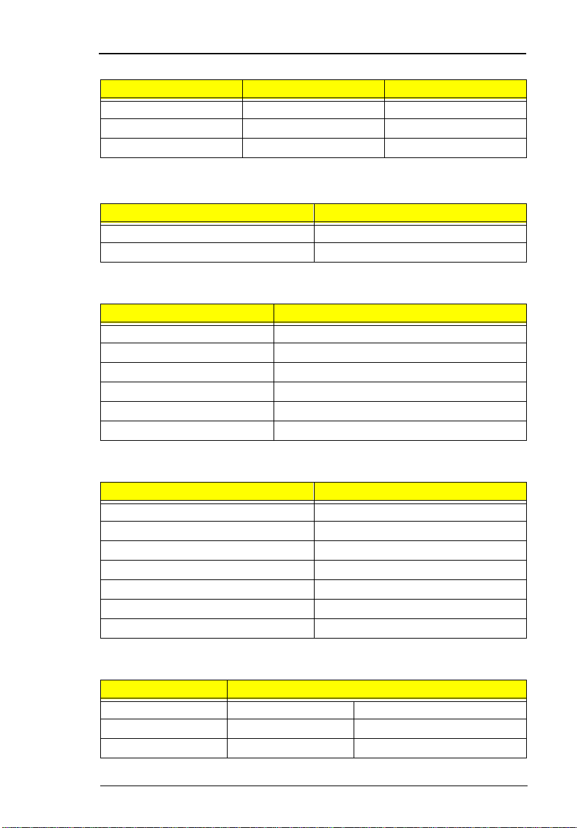
DIMM Combinations
Slot 1 Slot 2 Total Memory
128MB 32MB 160MB
128MB 64MB 192MB
128MB 128MB 256MB
Video Memory
Item Specification
Fixed Fixed, built-in NM2200 video controller
Video memory size 2.35MB
Cache Memory
Item Specification
Cache controller ALi M1621-A1K
Cache size 256 KB (Dixon CPU type)
Cache size 128 KB (Celeron CPU type)
1st level cache control Always enabled
2st level cache control Always enabled
Cache scheme control Fixed in write-back
Video
Item Specification
Chip vendor Ne oM a gic
Chip name NM2 200C V.DH (NMG5)
Chip vo ltage 3.3 Volts
Supports ZV((Zoo med Video) port Yes
Graph interface (PCI/AGP) PCI bus/AGP bus
Maximun resolution (LCD) 1024 x 768 (16M colors)
Maximn un resolution (CRT) 1024x768 (16M colors)
Video Resoluti ons M odes
Resolution Refresh Rate
CRT Only LCD/CRT Simultaneous
640x480x256 85 60
640x480x64K 85 60
Chapter 1 17

Video Resoluti ons M odes
Resolution Refresh Rate
640x480x16M 85 60
800x600x256 85 60
800X600X64K 85 60
800X600X16M 85 60
1024x768x256 85 60
1024x768x64K 85 60
1024x768x16M 85 60
Parallel Port
Item Specification
Parallel port controller NS PC97338-A2
Number of parallel ports 1
Location Rear side
Connector type 25-pin D-type connector, in female type.
Parallel port function control Enable/Diable by BIOS Setup
Supports ECP Yes (set by BIOS setup)
Optional ECP DMA channel
(in BIOS Setup)
Optional parallel port I/O address
(in BIOS Setup)
Optional parallel port IRQ
(in BIOS Setup)
DMA channel 1
DMA channel 3
3BCh, 378h, 278h
IRQ5, IRQ7
Serial Port
Item Specification
Serial port contr oller N S P C97338-A2
Number of serial ports 1
Supports 16550 UART Yes
Connector type 9-pin D-type connector, i n male type
Location Rear side
Serial port function control Enable/disable by BIOS Setup
Optional serial port
(in BIOS Setup)
Optional serial port IRQ
(in BIOS Setup)
3F8h, 2F8h, 3E8h, 2E8h,
IRQ4, IRQ11
18 System Introduct ions

Audio
Item Specification
Audio Controller ESS Solo-1 E (ES 1946)
Audio onboard or optional Built-in
Mono or Stereo Stereo
Resolution 16-bit
Compatibility SB-Pro, Windows Sound System
Mixed sound source Voice, Synthesize r, Lin e-in,
Voice channe l 8 -/1 6- b it, mon o/stere o
Sampling rate 44.1 KHz
Internal microphone Yes, on the left-higher corner of LCD
Internal speaker / Quantity Yes / 2 pieces, on both hinge sides
Supports PnP DMA channel DMA channel 0
Supports PnP IRQ IRQ5
(WSS), MPU-401, OPL3, OPL3-SA3
Microphone, CD
panel
DMA ch an ne l 1
PCMCIA
Item Specification
PCMCIA controller O2 OZ6833T D Version
Supports card type Type-II / type-III
Number of slots Two type-II or one type-III
Access location Right side
Supports ZV (Zoomed Video) port Y es (for upper slot)
Supports 32 bit CardBus Yes (IRQ9, for both slots)
Modem
Item Specification
Chipset Lucent 1646
Fax modem data baud rate (bps) 14.4 K
Data modem data baud rate (bps) 56 K
Supports modem protocol V.90 data modem, V. 17 fax modem,
and digital line protection operation
Modem connector type RJ45 (Capable of RJ11)
Modem connector loc ation Right si de
Chapter 1 19
Keyboard
Item Specification
Keyboard controller Mitsubishi M38867 VJG TQFP
Keyboard vendor & model name API
Total num b er of ke yp ads 84-/85-/88-key
Windows 95 keys Yes
Internal & external keyboard work
simultaneously
Yes
Diskette Drive
Item Specification
Vendor & model name Mitsu mi D353F3
Floppy Disk Specifications
Media reco gnition 2DD (720KB ) 2HD (1.2MB ,
3-mode )
Sectors / track 9 15 18
Tracks 80 80 80
Data transfer rate (Kbit/s)250 500 500
2HD (1.44MB)
Rotational speed
(RPM)
Read/write heads 2
Encoding method MFM / FM
Power Requirement
Input Voltage (V) +5V ±10%
300 360 300
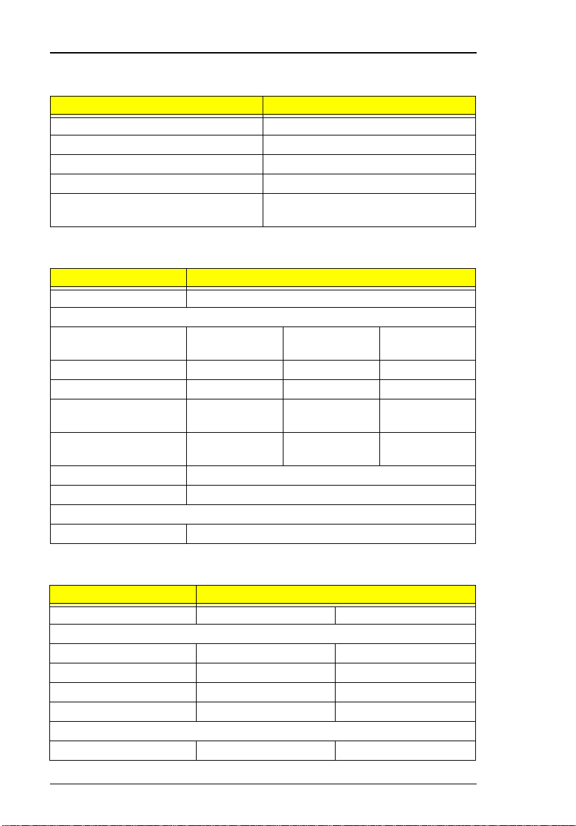
Hard Disk Drive
Item Specification
Vendor & Model Name IBM DKLA-2 4320 IBM DADA -26480
Drive Format
Capacity (MB) 4320 6480
Bytes per sector 512 512
Logical heads 15 15
Logical sectors 63 63
Drive Format
Logical cylinders 8944 13424
20 System Introduct ions

Hard Disk Drive
Item Specification
Physical read/write heads 4 6
Disks 2 3
Spindle speed (RPM) 4200 4200
Performance Specifications
Buffer size 512KB 512KB
Interface IDE(ATA-4) IDE(ATA-4)
Data transfer rate (disk-
buffer, Mbytes/s)
Data transfer rate
(host~buffer, Mbytes/s)
DC Power Requirements
Voltage tolerance 5+-5% 5+-5%
7.7~12.8 61.5~102.6
16.6 (PIO mode 4)
33.3 (Ultra DMA mode
2)
16.6 (PIO mode 4)
33.3 (Ultra DMA mode
2)
CD-ROM
Item Specification
Vendor & Model Name TEAC CD-224E-A26
Performance Specification
Transfer rate (KB/sec) 1,546KB/sec ~ 3,600KB/sec. (FULL -
CAV)
Access time (typ.) 130 msec. (typ)
Rotation speed 5136 rpm (typ.)
Buffer memory 128KB
Interface ATAPI
Applicable disc format CD-DA, CD-ROM (Mode-1, Mode-2), CD-
ROM XA MODE-2 (FORM-1, FORM-2),
Multi-Session Photo CD, CD-I, Video CD,
Enhanced CD & CD PLUS Compatible,
CD-R/W
Loadin g mechanism Draw er with soft eject and emergency
eject hole
Power Requirement
Input Voltage 5 V
Chapter 1 21

Battery Pack
Item Specification
Vendor & model name Sanyo BTP-2231
Battery Type Li-Ion
Pack capacity 3200 mAH
Cell voltage 3.7 V
Number of battery call 8
Packag e co nfigura tio n 2P4S
Packag e voltage 1 4.8V
DC-DC/Charger Board
Item Specification
Vendor & model name Ambit T62.120.C.00
Input voltage AC adapter: 19V-21V
Battery: 12V-16.8V
DC/DC converter output
Output rating CD-
5V
Current (w/load, A) 0~2 0~3.5 0~0.25 0.02 0~3.8
Charger output
Normal ch arg e (c har g e wh il e
system is not operative)
Backgound charge (charge
even system is still
operative)
Battery-lower 2 level (V) 14.1V
Battery-low 3 level (V) 12V
Protection
Charger protection Security timer control
DC/DC converter protection OVP (Over Voltage Protection, V)
2.2A
0.5A
Over temperature protection
Over voltage protection
OCP (Over Current Protection, A)
3.3V +12V 5V
SB
Pri5V
SB
22 System Introduct ions
 Loading...