

Acer Travelmate 4650, Travelmate 4150 Service Manual

TravelMate 4650
TravelMate 4150
Service Guide
Service guide files and updates are available
on the ACER/CSD web; for more information,
please refer to http://csd.acer.com.tw
PRINTED IN TAIWAN

Revision History
Please refer to the table below for the updates made on TravelMate 4650 and TravelMate 4150 service guide.
Date Chapter Updates
II

Copyright
Copyright © 2005 by Acer Incorporated. All rights reserved. No part of this publication may be reproduced,
transmitted, transcribed, stored in a retrieval system, or translated into any language or computer language, in
any form or by any means, electronic, mechanical, magnetic, optical, chemical, manual or otherwise, without
the prior written permission of Acer Incorporated.
Disclaimer
The information in this guide is subject to change without notice.
Acer Incorporated makes no representations or warranties, either expressed or implied, with respect to the
contents hereof and specifically disclaims any warranties of merchantability or fitness for any particular
purpose. Any Acer Incorporated software described in this manual is sold or licensed "as is". Should the
programs prove defective following their purchase, the buyer (and not Acer Incorporated, its distributor, or its
dealer) assumes the entire cost of all necessary servicing, repair, and any incidental or consequential
damages resulting from any defect in the software.
Acer is a registered trademark of Acer Corporation.
Intel is a registered trademark of Intel Corporation.
Pentium and Pentium II/III are trademarks of Intel Corporation.
Other brand and product names are trademarks and/or registered trademarks of their respective holders.
III

Conventions
The following conventions are used in this manual:
SCREEN
MESSAGES
NOTE Gives bits and pieces of additional
WARNING Alerts you to any damage that might
CAUTION Gives precautionary measures to
IMPORTANT Reminds you to do specific actions
Denotes actual messages that appear
on screen.
information related to the current
topic.
result from doing or not doing specific
actions.
avoid possible hardware or software
problems.
relevant to the accomplishment of
procedures.
IV

Preface
Before using this information and the product it supports, please read the following general information.
1. This Service Guide provides you with all technical information relating to the BASIC CONFIGURATION
decided for Acer's "global" product offering. To better fit local market requirements and enhance product
competitiveness, your regional office MAY have decided to extend the functionality of a machine (e.g.
add-on card, modem, or extra memory capability). These LOCALIZED FEATURES will NOT be covered
in this generic service guide. In such cases, please contact your regional offices or the responsible
personnel/channel to provide you with further technical details.
2. Please note WHEN ORDERING FRU PARTS, that you should check the most up-to-date information
available on your regional web or channel. If, for whatever reason, a part number change is made, it will
not be noted in the printed Service Guide. For ACER-AUTHORIZED SERVICE PROVIDERS, your Acer
office may have a DIFFERENT part number code to those given in the FRU list of this printed Service
Guide. You MUST use the list provided by your regional Acer office to order FRU parts for repair and
service of customer machines.
V

Table of Contents
Chapter 1 System Specifications 1
Features . . . . . . . . . . . . . . . . . . . . . . . . . . . . . . . . . . . . . . . . . . . . . . . . . . . . . . . .1
Mainboard Placement . . . . . . . . . . . . . . . . . . . . . . . . . . . . . . . . . . . . . . . . . . . . . . 5
Top View . . . . . . . . . . . . . . . . . . . . . . . . . . . . . . . . . . . . . . . . . . . . . . . . . . . . 5
Bottom View. . . . . . . . . . . . . . . . . . . . . . . . . . . . . . . . . . . . . . . . . . . . . . . . . .6
Block Diagram . . . . . . . . . . . . . . . . . . . . . . . . . . . . . . . . . . . . . . . . . . . . . . . . . . .8
Outlook View . . . . . . . . . . . . . . . . . . . . . . . . . . . . . . . . . . . . . . . . . . . . . . . . . . . . .9
Front View . . . . . . . . . . . . . . . . . . . . . . . . . . . . . . . . . . . . . . . . . . . . . . . . . . .9
Close Front View . . . . . . . . . . . . . . . . . . . . . . . . . . . . . . . . . . . . . . . . . . . . .10
Left View . . . . . . . . . . . . . . . . . . . . . . . . . . . . . . . . . . . . . . . . . . . . . . . . . . . 11
Right View . . . . . . . . . . . . . . . . . . . . . . . . . . . . . . . . . . . . . . . . . . . . . . . . . .12
Rear View . . . . . . . . . . . . . . . . . . . . . . . . . . . . . . . . . . . . . . . . . . . . . . . . . .13
Bottom View. . . . . . . . . . . . . . . . . . . . . . . . . . . . . . . . . . . . . . . . . . . . . . . . .14
Using the Keyboard . . . . . . . . . . . . . . . . . . . . . . . . . . . . . . . . . . . . . . . . . . . . . .15
Lock Keys and Embedded Numic Keypad. . . . . . . . . . . . . . . . . . . . . . . . . .15
Windows Key . . . . . . . . . . . . . . . . . . . . . . . . . . . . . . . . . . . . . . . . . . . . . . . .16
Hot Keys . . . . . . . . . . . . . . . . . . . . . . . . . . . . . . . . . . . . . . . . . . . . . . . . . . .17
Special Keys . . . . . . . . . . . . . . . . . . . . . . . . . . . . . . . . . . . . . . . . . . . . . . . .20
Indicators . . . . . . . . . . . . . . . . . . . . . . . . . . . . . . . . . . . . . . . . . . . . . . . . . . . . . . .21
Launch Keys . . . . . . . . . . . . . . . . . . . . . . . . . . . . . . . . . . . . . . . . . . . . . . . . 22
Touchpad . . . . . . . . . . . . . . . . . . . . . . . . . . . . . . . . . . . . . . . . . . . . . . . . . .23
Touchpad Basics . . . . . . . . . . . . . . . . . . . . . . . . . . . . . . . . . . . . . . . . . . . .23
Using a computer security lock . . . . . . . . . . . . . . . . . . . . . . . . . . . . . . . . . .25
Using System Utilities . . . . . . . . . . . . . . . . . . . . . . . . . . . . . . . . . . . . . . . . . . . . .26
Acer eManagement . . . . . . . . . . . . . . . . . . . . . . . . . . . . . . . . . . . . . . . . . . .26
Launch Manager . . . . . . . . . . . . . . . . . . . . . . . . . . . . . . . . . . . . . . . . . . . . .27
Audio . . . . . . . . . . . . . . . . . . . . . . . . . . . . . . . . . . . . . . . . . . . . . . . . . . . . . . . . . .28
Ejecting the optical (CD or DVD) drive tray . . . . . . . . . . . . . . . . . . . . . . . . . . . . . 29
Using a Computer Security Lock . . . . . . . . . . . . . . . . . . . . . . . . . . . . . . . . . . . . . 30
System Power Management . . . . . . . . . . . . . . . . . . . . . . . . . . . . . . . . . . . . . . . . 31
Hardware Specifications and Configurations . . . . . . . . . . . . . . . . . . . . . . . . . . . .32
Chapter 2 System Utilities 43
BIOS Setup Utility . . . . . . . . . . . . . . . . . . . . . . . . . . . . . . . . . . . . . . . . . . . . . . . .43
Buttons. . . . . . . . . . . . . . . . . . . . . . . . . . . . . . . . . . . . . . . . . . . . . . . . . . . . . . . . .44
Application Launch Buttons . . . . . . . . . . . . . . . . . . . . . . . . . . . . . . . . . . . . .44
Power Button . . . . . . . . . . . . . . . . . . . . . . . . . . . . . . . . . . . . . . . . . . . . . . . .44
Power Button Over-ride . . . . . . . . . . . . . . . . . . . . . . . . . . . . . . . . . . . . . . .44
Lid Switch. . . . . . . . . . . . . . . . . . . . . . . . . . . . . . . . . . . . . . . . . . . . . . . . . . .44
Hard Disk Password Function/ Password on boot function . . . . . . . . . . . . . . . .45
Valid Password Characters . . . . . . . . . . . . . . . . . . . . . . . . . . . . . . . . . . . . . 45
Information . . . . . . . . . . . . . . . . . . . . . . . . . . . . . . . . . . . . . . . . . . . . . . . . . . . . .46
Main . . . . . . . . . . . . . . . . . . . . . . . . . . . . . . . . . . . . . . . . . . . . . . . . . . . . . . . . . . 48
Advanced . . . . . . . . . . . . . . . . . . . . . . . . . . . . . . . . . . . . . . . . . . . . . . . . . . . . . .49
Security . . . . . . . . . . . . . . . . . . . . . . . . . . . . . . . . . . . . . . . . . . . . . . . . . . . . . . . .51
Boot . . . . . . . . . . . . . . . . . . . . . . . . . . . . . . . . . . . . . . . . . . . . . . . . . . . . . . . . . . 52
Exit . . . . . . . . . . . . . . . . . . . . . . . . . . . . . . . . . . . . . . . . . . . . . . . . . . . . . . . . . . .53
VII

Table of Contents
Chapter 3 Machine Disassembly 55
General Information . . . . . . . . . . . . . . . . . . . . . . . . . . . . . . . . . . . . . . . . . . . . . .56
Removing the Battery Pack . . . . . . . . . . . . . . . . . . . . . . . . . . . . . . . . . . . . . . . . .57
Removing the HDD and ODD Module . . . . . . . . . . . . . . . . . . . . . . . . . . . . . . . . . 58
Removing the RAM . . . . . . . . . . . . . . . . . . . . . . . . . . . . . . . . . . . . . . . . . . . . . . .58
Removing the Keyboard . . . . . . . . . . . . . . . . . . . . . . . . . . . . . . . . . . . . . . . . . . .58
Removing the Wireless and LCD Panel . . . . . . . . . . . . . . . . . . . . . . . . . . . . . . .59
Removing the Thermal and Bluetooth Module . . . . . . . . . . . . . . . . . . . . . . . . . .59
Removing the Upper Case . . . . . . . . . . . . . . . . . . . . . . . . . . . . . . . . . . . . . . . . .59
Removing the Touchpad . . . . . . . . . . . . . . . . . . . . . . . . . . . . . . . . . . . . . . . . . . . 60
Removing the FAN . . . . . . . . . . . . . . . . . . . . . . . . . . . . . . . . . . . . . . . . . . . . . . .61
Removing the Thermal Module and CPU . . . . . . . . . . . . . . . . . . . . . . . . . . . . . .61
Removing the MDC . . . . . . . . . . . . . . . . . . . . . . . . . . . . . . . . . . . . . . . . . . . . . . .62
Removing the Wireless, Speaker and PCMCIA . . . . . . . . . . . . . . . . . . . . . . . . .62
Removing the LCD Panel . . . . . . . . . . . . . . . . . . . . . . . . . . . . . . . . . . . . . . . . . .63
Removing the HDD and ODD . . . . . . . . . . . . . . . . . . . . . . . . . . . . . . . . . . . . . . .65
Chapter 4 Troubleshooting 66
System Check Procedures . . . . . . . . . . . . . . . . . . . . . . . . . . . . . . . . . . . . . . . . .67
External Diskette Drive Check . . . . . . . . . . . . . . . . . . . . . . . . . . . . . . . . . .67
External CD-ROM Drive Check . . . . . . . . . . . . . . . . . . . . . . . . . . . . . . . . . 67
Keyboard or Auxiliary Input Device Check . . . . . . . . . . . . . . . . . . . . . . . . .67
Memory Check . . . . . . . . . . . . . . . . . . . . . . . . . . . . . . . . . . . . . . . . . . . . . .68
Power System Check . . . . . . . . . . . . . . . . . . . . . . . . . . . . . . . . . . . . . . . . .68
Check the Power Adapter . . . . . . . . . . . . . . . . . . . . . . . . . . . . . . . . . . . . . .69
Check the Battery Pack . . . . . . . . . . . . . . . . . . . . . . . . . . . . . . . . . . . . . . . 70
Touchpad Check . . . . . . . . . . . . . . . . . . . . . . . . . . . . . . . . . . . . . . . . . . . . 70
PhoenixBIOS POST Tasks and Beep Codes . . . . . . . . . . . . . . . . . . . . . . . . . . .71
Index of Error Messages . . . . . . . . . . . . . . . . . . . . . . . . . . . . . . . . . . . . . . . . . . .72
POST Code . . . . . . . . . . . . . . . . . . . . . . . . . . . . . . . . . . . . . . . . . . . . . . . . . . . . . 75
Index of Symptom-to-FRU Error Message . . . . . . . . . . . . . . . . . . . . . . . . . . . . .76
Intermittent Problems. . . . . . . . . . . . . . . . . . . . . . . . . . . . . . . . . . . . . . . . . . . . . .79
Undetermined Problems . . . . . . . . . . . . . . . . . . . . . . . . . . . . . . . . . . . . . . . . . . .80
Use NAPP CD to Build Master Hard Disc Drive . . . . . . . . . . . . . . . . . . . . . . . . .81
Chpater 5 Jumper and Connector Locations 88
Top View . . . . . . . . . . . . . . . . . . . . . . . . . . . . . . . . . . . . . . . . . . . . . . . . . . . . . . .88
Rear View . . . . . . . . . . . . . . . . . . . . . . . . . . . . . . . . . . . . . . . . . . . . . . . . . . . . . .89
VGA Board. . . . . . . . . . . . . . . . . . . . . . . . . . . . . . . . . . . . . . . . . . . . . . . . . . . . . .91
Power SW/B . . . . . . . . . . . . . . . . . . . . . . . . . . . . . . . . . . . . . . . . . . . . . . . . . . . .92
TouchPad Board . . . . . . . . . . . . . . . . . . . . . . . . . . . . . . . . . . . . . . . . . . . . . . . . .93
Hot Swap ODD Board . . . . . . . . . . . . . . . . . . . . . . . . . . . . . . . . . . . . . . . . . . . . .94
DVI Board . . . . . . . . . . . . . . . . . . . . . . . . . . . . . . . . . . . . . . . . . . . . . . . . . . . . . . 95
Clear CMOS . . . . . . . . . . . . . . . . . . . . . . . . . . . . . . . . . . . . . . . . . . . . . . . . . . . .96
VIII

Table of Contents
Chapter 6 FRU (Field Replaceable Unit) List 97
Exploded Diagram . . . . . . . . . . . . . . . . . . . . . . . . . . . . . . . . . . . . . . . . . . . . . . .98
Parts . . . . . . . . . . . . . . . . . . . . . . . . . . . . . . . . . . . . . . . . . . . . . . . . . . . . . . . . 100
Appendix A Model Definition and Configuration 113
Appendix B Test Compatible Components 114
Microsoft Windows XP(Home/Professional) Environment Test . . . . . . . . . . . . 115
Appendix C Online Support Information 118
IX

Table of Contents
X

System Specifications
Features
This computer was designed with the user in mind. Here are just a few of its many features:
Performance
T Intel
T Intel
T CPU Package is uFPGA 478 Package
T Integrated Intel
Memory
T 256MB or 512MB of DDR II 400/533 memory
T Onboard with two 200-pin +1.8V DDR II soDIMM connector, supporting DDR memories card.
T Support 64MB/128MB VGA memory for NV43M/NV44MV
T Adjustable 128MB UMA VGA memory share from North Bridge
®
915PM/915GM PCI Express chipset
®
Pentium® M processor 730/740/750/760/770 (2MB L2 cache, 1.6/1.73/1.86/2.0/2.13 GHz,
533 MHz FSB)
®
PRO/Wireless 2200GB network connection (dual-mode 802.11b/g) Wi-Fi
TM
CERTIFIED
solution, supporting Acer SignalUp wireless technology
Maximum up gradable to 2GB by two 1GB soDIMM module
Chapter 1
Display
Graphics
T 15” XGA TFT LCD, supporting 1024x768 pixel resolution, 16.7 million colours
(for TravelMate 4150 series)
T 15” SXGA TFT LC D, su ppor ting 1400x105 0 pixel resolut ion, 16.7 mill ion colours
(for TravelMate 4650 series)
T nVIDIA
T nVIDIA
®
GeForceTM Go 6600 graphics processing unit (GPU) with 64MB or 128MB of DDR Video
RAM , supporting PCI Express
®
GeForceTM Go 6200 graphics processing unit (GPU) with TurboCacheTM technology
TM
and Microsoft® DirectX® 9.0 (for TravelMate 4650 series)
supporting 128MB video memory supporting PCI Express
TM
and Microsoft® DirectX® 9.0 (for
TravelMate 4150 series)
T Intel
T Dual independent display support
T External resolution/refresh rate
T MPEG-2/DVD hardware-assisted capability
®
915GM integrated 3D graphics, featuring Intel® Graphics Media Accelerator 900 and up to
128MB of video memory, supporting Microsoft
T 2048x1536: 85/75/70/66/60 Hz
T 1600x1200: 120/100/85/75/60 Hz
T 1280x1024: 180/160/120/100/90/85/75/70/60 Hz
T 1024x768: 200/160/150/120/100/90/85/75/72/70/60 Hz
T 800x600: 200/160/120/100/90/85/75/72/70/60 Hz
®
DriectX® 9.0 (for TravelMate 4650/4150 series)
Chapter 1 1

Audio
Storage
T S-video/TV-out (NTSC/PAL) support
T Realtek ALC250 for AC’97 CODEC
T 16-bit AC’97 stereo audio
T Dual speakers and one internal microphone
T Separate audio ports for headphone-out , and line-in/microphone-in devices
T 20-bit Stereo DAC (Digital-to-Analog Converters) and 18-bit ADC (Analog-to-Digital Converters)
resolution
T Built-in 7-band digital hardware equalizer to optimize speaker response
T Support S/PDIF output
T Stereo output with 6-bit volume control
T Mono output with 5-bit volume control
T Headphone output with 50mW/20Ohm amplifier
T Three analog line-level stereo inputs with 5-bit volume control: LINE_IN, CD, AUX
T Two analog line-level mono inputs: PCBEEP, PHONE-IN
T High quality differential CD input
T 40/60/80/100 GB (4200 rpm) or 60GB (5400 rpm) P- ATA/100 hard disc drive
T One internal optical drive (DVD-Dual double layer, DVD-Super Multi double layer, or DVD/CD-RW
combo drive)
T AcerMedia Bay for hot-swappable optical drive modules(for TravelMate 4650 series)
T DVD-Super Multi double layer
T DVD Dual double layer
T DVD/CD-RW combo
T Optical drive options (for TravelMate 4150 series)
T DVD Dual double layer
T DVD/CD-RW combo
T 6-in-1 card reader supporting
T Smart Media (SM)
T Secure Digital (SD)
T MultiMedia Card (MMC)
T Memory Stick
T Memory Stick PRO
T xD-Picture Card
®
(MS)
TM
TM
(MS-Pro)
2 Chapter 1

Communication
T 56Kbps ITU V.92 modem with PTT approval, Wake-On-Ring ready
T 10/100/1000 Mbps Fast Ethernet; Wake-on-LAN ready (for TravelMate 4650 series)
T 10/100 Mbps Fast Ethernet; Wake-on-LAN ready (for TravelMate 4150 series)
T Integrated Intel
CERTIFIED
T Integrated Bluetooth
I/O Ports
T Four USB 2.0 ports
T IEEE 1394 port
T Ethernet (RJ-45) port
T Modem (RJ-11) port
T External display (VGA) port
T S-video/TV-out (NTSC/PAL) port
T Microphone/Line-in jack
T Headphones/Speaker/Line-out port
T Infrared (FIR) port
T PC Card slot (one Type II)
T 6-in-1 card reader (SM/MS/MS-Pro/MMC/SD/xD-Picture card
T DC-in jack for AC adaptor
T DVI-D port (for TravelMate 4650 series)
T 124-pin Acer ezDock connector (for TravelMate 4650 series)
®
PRO/Wireless 2200GB network connection (dual-mode 802.11b/g) Wi-Fi
TM
solution, supporting Acer SignalUp wireless technology
®
support (manufacturing option)
TM
)
Battery
T ACPI 1.0b CPU power management standard supports Standby and Hibernation power-saving
modes
T 65W,8 cell Li-ion battery pack
T optional 42W 6 cell Li-ion 2
T 5-hour battery life on Intel 915GM models
T 2.5-hour rapid charge; 3.5-hour charge-in-use
T 3 pin 65W AC adaptor
Keyboard and pointing device
T Acer FineTouch
T Ergonomically-centerd touchpad pointing device with 4-way internet function
TM
keyboard with a 5-degree curve, 88/89-key Windows keyboard
Weight (with battery)
T 6.26 lbs (2.84 Kg)
Dimension
T 336.4(W) x 284.5 (D) x 32.0/34.5 (H) mm (14.29 x 10.46 x 1.2/1.35 inches)
nd
battery pack (for TravelMate 4650)
Chapter 1 3

Environment
T Temperature
T Operating : 5
T Non-operating : -20
T Humidity (non-condensing)
T Operating : 20% - 80%
T Non-Operating : 20% - 80% RH
System Compliance
T ACPI 1.0b
T Mobile PC 2001
T DMI 2.0
T Wi-Fi
T Cisco Compatible Extensions version 3 (CCX-V3)
®
Options
T 256MB/512MB/1GB DDR II 533MHz memory upgrades modules
T Additional 65W AC adaptor
T Additional eight-cell Li-ion battery pack
T External USB floppy drive
T Second 6-cell battery pack (AcerMedia Bay, for TravelMate 4650 series)
T DVD-Super Multi double layer drive (AcerMedia Bay, for TravelMate 4650 series)
T Acer ezDock (for TravelMate 4650 series)
o
C-35oC
o
C~65oC
NOTE: The specifications listed above are for reference only. The exact configuration of your PC depends on
the model purchased.
4 Chapter 1
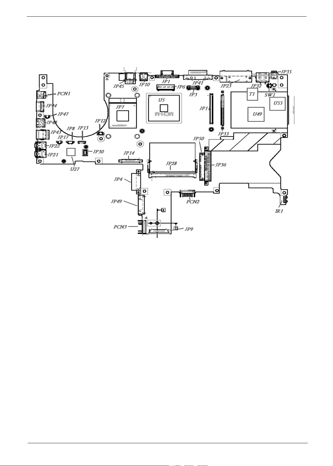
Mainboard Placement
Top View
Chapter 1 5
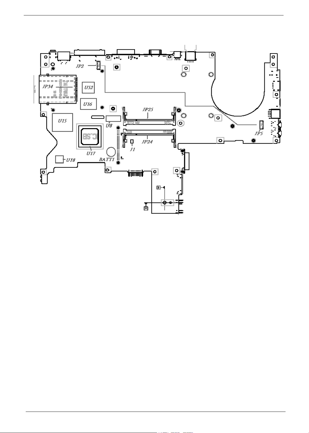
Bottom View
6 Chapter 1
ITEM DESCRIPTION ITEM DESCRIPTION
JP1 CRT CONN JP30 MDC CONN
JP2 DOCKING SPR CONN JP32 RJ45 CONN
JP3 SWITCH CONN JP33 CARDBUS CONN
JP4 ODD CONN (FIX) JP34 5 IN 1 SOCKET
JP5 DOCKING SPR CONN JP35 1394 CONN
JP6 LCD CONN JP36 HDD CONN
JP7 CPU SOCKET JP41 DVI-D CONN
JP8 SPEAKER CONN JP43 DUAL USB CONN
JP9 TP/B CONN JP44/JP45 USB CONN
JP10 S-VIDEO CONN JP47 RJ11 TO MDC CONN
JP11 VGA /B CONN JP48 RJ11 CPMM
JP12 FAN CONN JP49 ODD CONN (SWAP)
JP13 BT CONN JP50 SATA CONN
JP14 KB CONN PCN1 DC JACK
JP15 ROM SOCKET PCN2 MAIN BAT
JP17 MIC CONN PCN3 2nd BAT
JP21 MIC JACK SW1 LID SWITCH
JP22 HEADPHONE JACK BATT1 BATTERY
JP23 DOCKIND CONN J1 CLEAR CMOS
JP24/JP25 DIMM SLOT IR1 IR CONN
JP28 MINI PCI SLOT
Chipset Chipset Description
U5 NB CHIPSET
U27 AUDIO CODEC
U49 LAN CHIP
U55 1394 CHIP
T1 LAN TRANSFORMER
U8 CLK GEN
U15 EC CHIP
U16 ROM SOCKET
U17 SB CHIP
U18 SUPER I/O
U52 5 IN 1 CHIP
Chapter 1 7
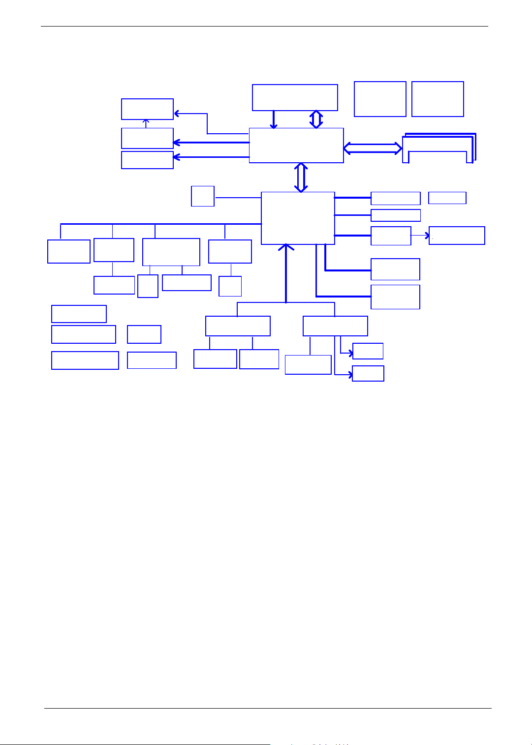
Block Diagram
page 28
BROADCOM
BCM5788M
BCM4401
Mini PCI
socket
RJ45 CONN
Power On/Off CKT.
DC/DC Interface CKT.
Power Circuit DC/DC
page 39
page 40
page 42~49
page 26
page 27
MV43 / MV44
VGA Board
CRT/TV-OUT
pa ge 1 5
pa ge 1 6
LCD CONN
pa ge 1 6
ENE Controller
CB714
5in1 CardReader
Slot 0
page 24
RTC CKT.
page 39
Power OK CKT.
page 39
Slot
PCI BUS
page 23,24
1394 Controller
TSB43AB21
page 24
SMsC LPC47N217
Parellel Port
page 38
PCI-E BUS
page 25
1394
Conn.
page 25
page 32
Serial Port
DOCKING CONNDOCKING CONN
page 38
Intel Dothan CPU
page 4,5
H_A#(3..31)
FSB
400 / 533 Mhz
Intel Alviso GM(PM)
PCBGA 1257
page 6,7,8,9,10
DMI
Intel ICH6-M
mBGA-609
page 17,18,19,20
LPC BUS
ENE KB910/910L
Touch Pad
page 34
CONN.
H_D#(0..63)
Signal Channel DDR-1
Two Channel DDR-2
USB 2.0
USB 2.0
AC-LINK
SATA
PATA
page 33
Thermal Sensor
ADM1032ARM
page 4
DDR-2
USB conn x 4
BT Conn
Audio CKT
ALC 250 -D
PATA HDD
SATA HDD
MODULE
Connector
Int. KBD
page 34
BIOS
page 35
Clock Generator
ICS954226AGT
DDR-SO-DIMM X2
BANK 0, 1, 2, 3
page 37
page 34
page 29
conn
page 21
page 21
page 14
page 11,12,13
RJ1 1 CONN
page 36
AMP & Audio Jack
page 31
8 Chapter 1
Outlook View
Just for Starters...
A general introduction of ports allow you to connect peripheral devices, as you would with a desktop PC.
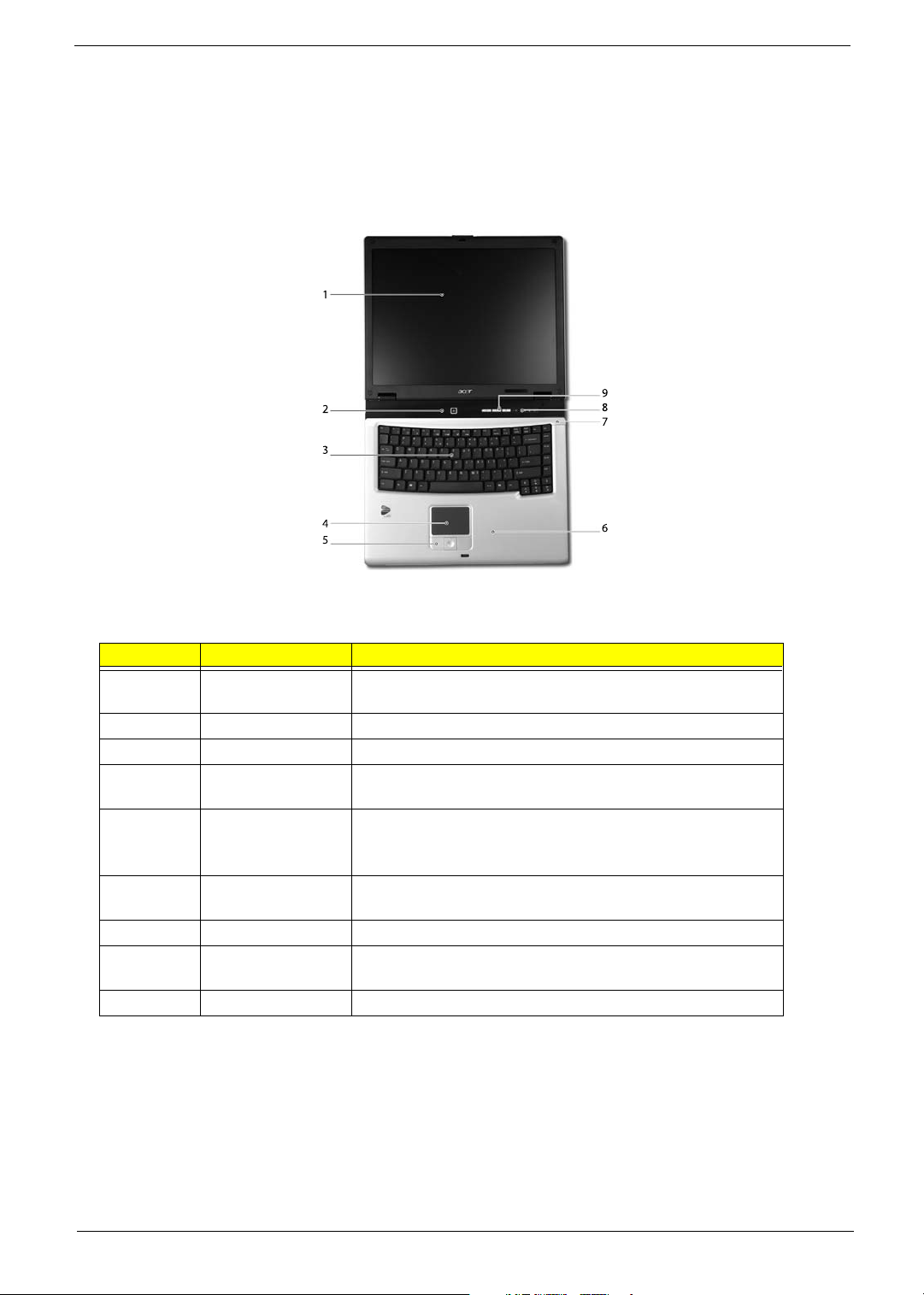
Front View
# Item Description
1 Display screen Also called Liquid-Crystal Display (LCD), displaying computer
output.
2 Power button Turns the computer on and off
3 Keyboard Inputs data into your computer.
4 Touchpad Touch-sensitive pointing device which functions like a
computer mouse.
5 Click buttons
(Left, center and
right)
6 Palmrest Comfortable support area for your hands when you use the
7 Microphone Internal microphone for sound recording.
8 Status indicators Light-Emitting Diodes (LEDs) that turn on and off to show the
9 Launch keys Buttons for launching frequently used programs.
The left and right buttons function like the left and right mouse
buttons; the center button serves as a 4-way scroll button.
computer.
status of the computer's functions and components.
Chapter 1 9
Closed Front View
"Launch keys" on page 10
# Item Description
1 Speakers Left and right speakers deliver stereo audio output.
2 Bluetooth
communication
button/indicator
3Wireless
communication
button/indicator
4 Power indicator Lights when the computer is on.
5 Battery indicator Lights when the battery is being charged.
6 Latch Locks and releases the lid.
Press to enable/disable Bluetooth function. Lights to indicate
the status of Bluetooth communications (manufacturing
option).
Press to enable/disable Wireless function. Lights to indicate
the status of wireless LAN communications.
10 Chapter 1
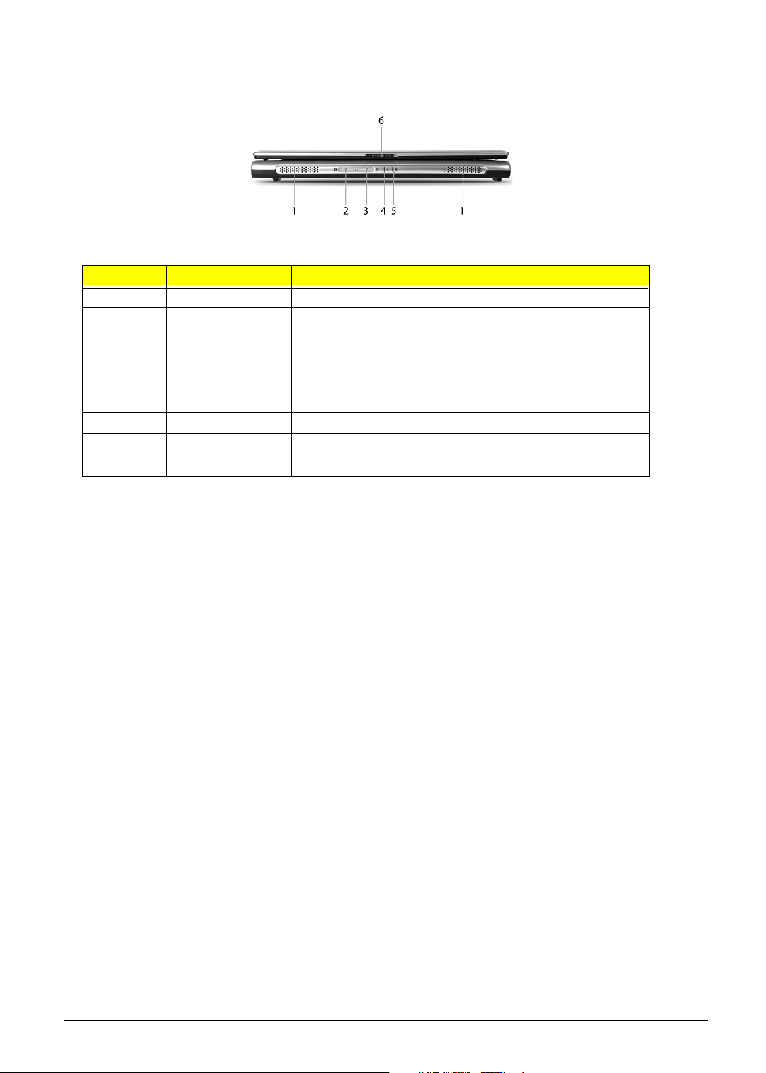
Left View
"Launch keys" on page 10
"Launch keys" on page 10
No. Icon Item Description
1 Security keylock Connects to a Kensington-compatible
2 Power jack Connects to an AC adaptor.
3/5 USB 2.0 port Connects to Universal Serial Bus (USB) 2.0
computer security lock.
devices (e.g., USB mouse, USB camera).
4 Modem Jack (RJ-11) Connects to a phone line.
6 Speaker-out/line-out/
headphone jack
7 Line-in/mic-in jack Accepts inputs from external microphones.
8 Optical drive Internal optical drive; accepts CDs or DVDs
9 Optical drive eject button Ejects the optical drive tray from the drive.
Connects to audio line-out devices (e.g.,
speakers, headphones).
depending on the optical drive type.
Chapter 1 11
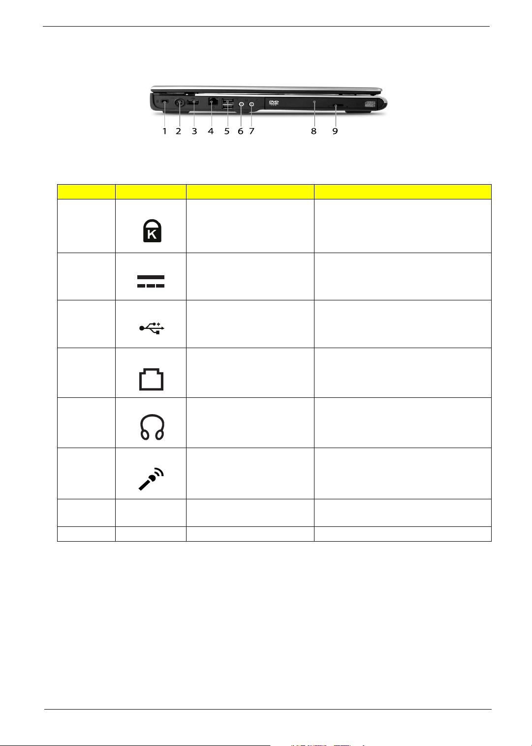
Right View
Note:
Note:
# Icon Item Description
1 Infrared port Interfaces with infrared devices (e.g., infrared printer
2 Hard disk bay Houses the computer's hard disk (secured by a
3 PC Card slot eject
4 6-in-1 card reader Accepts MS, MS PRO, MMC, SD, SM, and xD-
and IR-aware computer).
screw).
Ejects the PC Card from the slot.
button
Picture cards.
NOTE: Only one card can operate at any given
time.
5 PC Card Slot Connects to one Type II CardBus PC Card.
12 Chapter 1
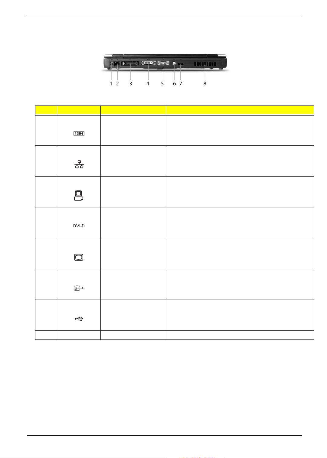
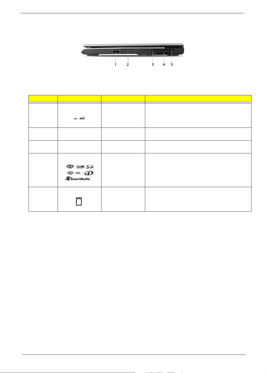
Rear View
# Item Description
1 IEEE 1394 port Connects to IEEE 1394 devices.
2 Network jack Connects to an Ethernet 10/100/1000-based network (for
selected models).
3 124-pin Acer ezDock
connector (for
TravelMate 4650 Series)
4 DVI-D port (for
TravelMate 4650 Series)
5 External display port Connects to a display device
6 S-video port Connects to a television or display device with S-video
7 USB 2.0 port Connects to Universal Serial Bus (USB) 2.0 devices (e.g.,
8 Ventilation slots Enable the computer to stay cool, even after prolonged use.
Connects to Acer ezDock.
Supports digital video connections.
(e.g., external monitor, LCD projector).
input.
USB mouse, USB camera).
Chapter 1 13
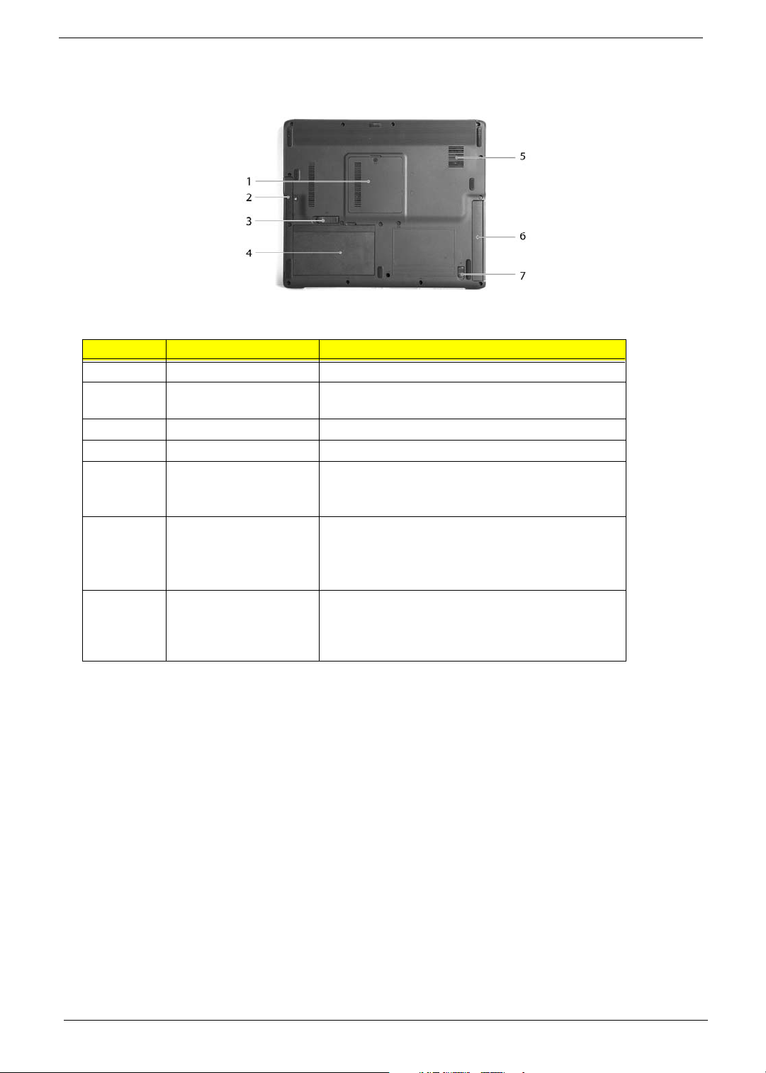
Bottom View
# Item Description
1 Memory compartment Houses the computer's main memory.
2 Hard disk bay Houses the computer's hard disk (secured by a
3 Battery release latch Unlatches the battery to remove the battery pack.
4 Battery bay Houses the computer's battery pack.
5 Cooling fan Helps keep the computer cool.
6 AcerMedia Bay
(for TravelMate 4650
Series)
screw).
NOTE: Do not cover or obstruct the opening of
the fan.
Houses an optical drive module or a second battery
pack.
7 AcerMedia Bay release
latch
(for TravelMate 4650
Series)
Unlatches the AcerMedia module for removal of
module.
14 Chapter 1
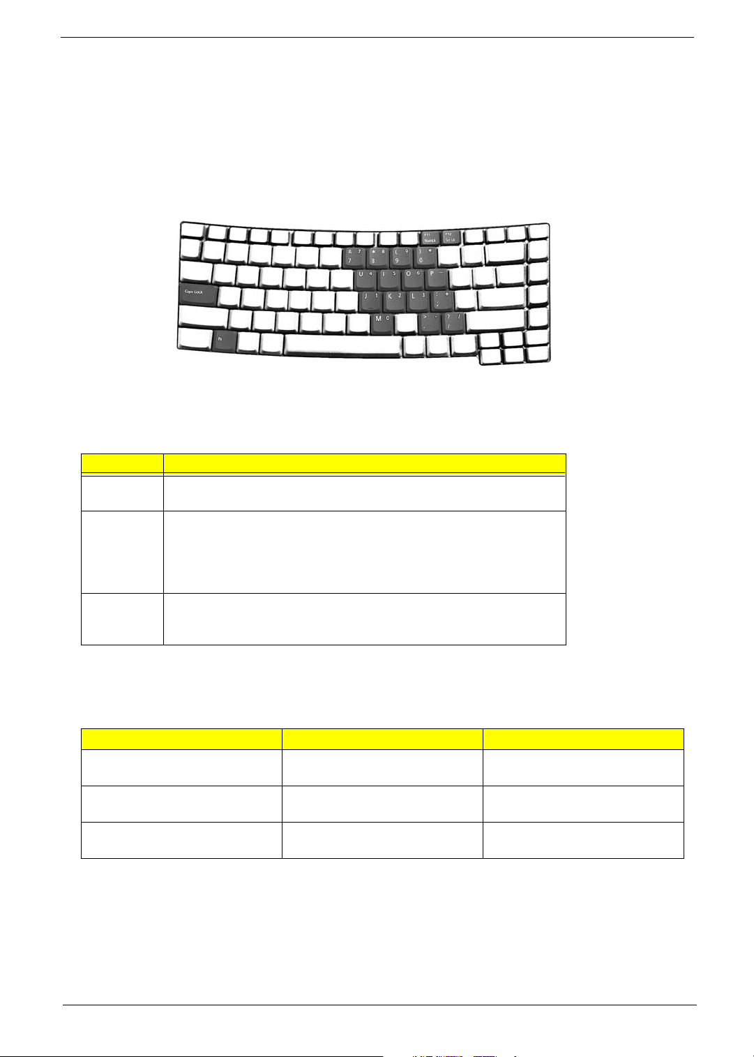
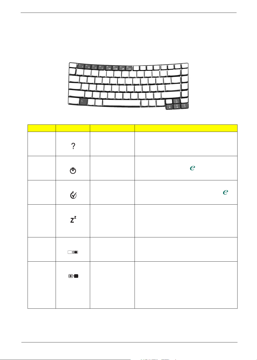
Using the Keyboard
The keyboard has full-sized keys and an embedded keypad, separate cursor keys, two Windows keys
and twelve function keys.
Lock keys and embedded numeric keypad
The keyboard has three lock keys which you can toggle on and off.
The computer features three lock keys, each with its own status indicator light.
Lock Key Description
Caps Lock When Caps Lock is on, all alphabetic characters are typed in
uppercase.
Num lock
<Fn+F11>
Scroll lock
<Fn+F12>
When Num Lock is on, the embedded keypad is in numeric mode.
The keys function as a calculator (complete with the arithmetic
operators +, -, *, and /). Use this mode when you need to do a lot of
numeric data entry. A better solution would be to connect an external
keypad.
When Scroll Lock is on, the screen moves one line up or down when
you press the up or down arrow keys respectively. Scroll Lock does
not work with some applications.
The embedded numeric keypad functions like a desktop numeric keypad. It is indicated by small
characters located on the upper right corner of the keycaps. To simplify the keyboard legend, cursorcontrol key symbols are not printed on the keys.
Desired access Num Lock on Num Lock off
Number keys on embedded
keypad
Cursor-control keys onembedded
keypad
Main keyboard keys Hold <Fn> while typing letters on
Chapter 1 15
Type numbers in a normal
manner.
Hold <Shift> while using cursor-
control keys.
embedded keypad.
Hold <Fn> while using cursorcontrol keys.
Type the letters in a normal
manner.
Windows Key
< > + <Tab>
< > + <E>
< > + <F1>
< > + <F>
< > + <M>
<Shift> + < > + <M>
< > + <M>
+ <R>
The keyboard has two keys that perform Windows-specific functions.
Key Description
Windows Key Pressed alone, this key has the same effect as
clicking on the Windows Start button; it launches the
Start menu. It can also be used with other keys to
provide a variety of functions:
< > + <Tab> Activates the next Taskbar button.
< > + <E> Opens the My Computer window.
< > + <F1> Opens Help and Support.
< > + <M> Minimises all windows.
<Shift> + < > + <M> Undoes the minimise all
windows
< > + <M> Action.
< > + <R> Opens the Run dialog box.
Application Key This key has the same effect as clicking the right
mouse button; it opens the application's context
menu.
16 Chapter 1
Hot Keys
<Fn>
< > + <Tab>
< > + <E>
< > + <F1>
< > + <F>
< > + <M>
<Shift> + < > + <M>
< > + <M>
+ <R>
"Acer eManager" on page 19
"Acer eManager" on page 19
"Acer eManager" on page 19
"Acer eManager" on page 19
"Acer eManager" on page 19
"Acer eManager" on page 19
"Acer eManager" on page 19
The computer employs hot keys or key combinations to access most of the computer's controls like screen
brightness, volume output and the BIOS utility.
To activate hot keys, press and hold the <Fn> key before pressing the other key in the hot key combination.
Hot Key Icon Function Description
Fn+F1
Hot Key Help Menu
Fn+F2 Launch Acer eSettings Launches the Acer eSettings in the eManager set by
This key will cause a help message to appear on the
display device that describes the definition and functionality
of the unit hot keys. It is preferred to have the key activate a
graphical display.
Fn+F3 Acer
Fn+F4
Fn+F5
Fn+F6
ePowerManagement
SleepButton in ACPI
mode
Launch Display Mode
Menu (DMM)
Display blank (backlight
off)
the Acer Empowering Key
Launches the Acer ePowerManagement in the
eManager set by the Acer Empowering Key
In ACPI mode, the OS provides two buttons for sleep
function. One is the Power On button and the other is the
Sleep Button. °Fn+F4° is assigned as the Sleep button in
ACPI mode. User can set the action of the Sleep Button on
the Power Management property.
Follow DMM Specification except in OS other than 32-bit
Windows
This key will cause the LCD back light to be turned off. This
provides both a quick security feature and some power
savings. The LCD back light can also be turned off via an
APM timer. The LCD back light will be turned on again
when any of the following events occur :
1. Any key pressed
2. Pointing device movement
Chapter 1 17
Hot Key Icon Function Description
"Acer eManager" on page 19
"Acer eManager" on page 19
"Acer eManager" on page 19
"Acer eManager" on page 19
"Acer eManager" on page 19
"Acer eManager" on page 19
"Acer eManager" on page 19
"Acer eManager" on page 19
Fn+F7 Touchpad On/Off
This key will cause the internal touchpad pointing device to
be disabled/enabled . This is to prevent accidental system
wake-ups from standby. Pressing this key a second time
will re-enable the touch pad pointing device. BIOS check
Internal AuxDev if not exist then BIOS empty return.
Fn+F8 Speaker On/Off
Fn+F11 Numlock
Fn+F12 Scroll Lock
Fn+w Volu me up
This key will cause the audio output to the speakers to
muted or disabled. Pressing this key a second time will reenable the audio output to the speakers.
The Num-Lock feature is a standard AT keyboard feature.
For Acer machines, Numlock is off by default and when the
NumLock is on, the internal keyboard will act as numeric
key padlock.
If an external keyboard or keypad is present, then the
NumLock will have the following definitions:
T NumLock is on, when the system boots
with external keyboard or numeric
keypad. The external keyboard/keypad
NumLock status is on and internal
keyboard overlay numeric keys are
disabled.
T NumLock key can be typed on/off via the
internal keyboard (Fn+F11) or the
external keyboard/keypad, but NumLock
affects the external keyboard/keypad
only.
T The NumLock shift state (NumLock is off)
is NOT used for the cursor movement by
the internal keyboard numeric keys.
T The state of the NumLock is not changed
by the attachment/removal (hot plug) of
the external keyboard/keypad.
This is to support the attachment of an external
numeric keypad. The user may use the internal
keyboard for full alphabet typing, and the external
keypad for numeric entry.
The state of the NumLock is not changed by the
attachment/removal of the external keyboard (hot
plug).
The Scroll Lock is a standard AT keyboard feature.
These keys can increase or decrease the brightness of the
LCD back light. This function should be handled by the
Analog function within the keyboard controller. Brightness
will step up/down one unit as each time these keys are
pressed.
Fn+y Volume down Decreases the sound volume.
18 Chapter 1

Hot Key Icon Function Description
"Acer eManager" on page 19
"Acer eManager" on page 19
"Acer eManager" on page 19
"Acer eManager" on page 19
Fn+x Brightness up
These keys can increase or decrease the brightness of the
LCD back light. This function should be handled by the
Analog function within
the keyboard controller. Brightness will step up/down one
unit as each time these keys are pressed.
Fn+z Brightness down
Fn+F10
Enter D2D recovery
during POST
Launch Acer eRecovery
in OS
Enter D2D recovery during POST
Launch Acer eRecovery in OS.
Chapter 1 19

Special Keys
You can locate the Euro symbol and the US dollar sign at the upper center and/or bottom-right of your
keyboard. To type:
The Euro symbol
1. Open a text editor or word processor.
2. Either directly press the Euro symbol at the bottom-right of the keyboard, or hold <Alt Gr> and then press
the Euro symbol at the upper-center of the keyboard.
The US dollar sign
1. Open a text editor or word processor.
2. Either directly press the dollar sign at the bottom-right of the keyboard, or hold <Shift> and then press the
dollar sign at the upper-center of the keyboard.
NOTE: This function varies according to the language settings.
20 Chapter 1
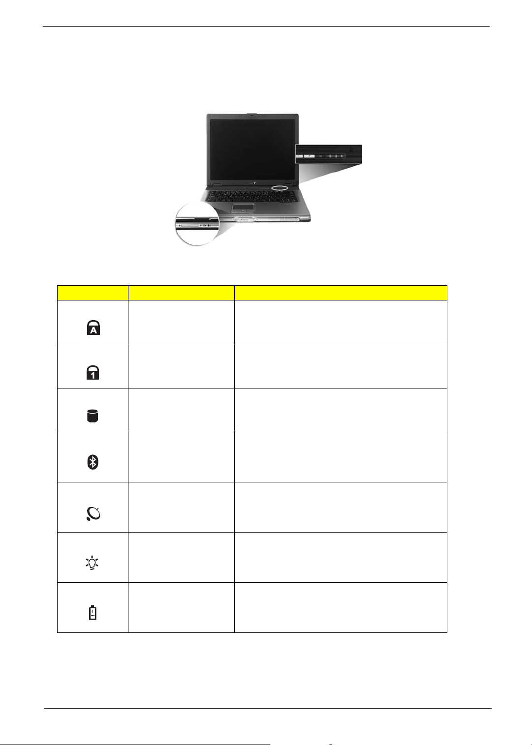
Indicators
Icon Function Description
The computer has three easy-to-read status icons on the upper-right above the keyboard, and four indicators
at the front panel.
The power, battery, and wireless communication status indicators are visible even when the LCD display is
closed.
Icon Item Description
Caps Lock Lights when Caps Lock is activated.
Num Lock Lights when Num Lock is activated.
Media activity Lights when the hard disk or optical drive is active.
Bluetooth indicator Lights to indicate the status of Bluetooth
Wireless indicator Lights to indicate the status of wireless LAN
Power indicator Lights when the computer is on.
Battery indicator Lights when the battery is being charged.
communications.
communications.
NOTE: 1. Charging : the light shows amber when the battery is charging.
2. Fully Charged : light shows green when in AC mode.
Chapter 1 21
 Loading...