

Acer Travelmate 380 Service Manual

Acer TravelMate 380 Series
Service Guide
Service guide files and updates are available
on the ACER/CSD web; for more information,
please refer to http://csd.acer.com.tw
Project Code: T58
PRINTED IN TAIWAN

Revision History
Please refer to the table below for the updates made on TravelMate 380 service guide.
Date Chapter Updates
II

Copyright
Copyright © 2004 by Acer Incorporated. All rights reserved. No part of this publication may be reproduced,
transmitted, transcribed, stored in a retrieval system, or translated into any language or computer language, in
any form or by any means, electronic, mechanical, magnetic, optical, chemical, manual or otherwise, without
the prior written permission of Acer Incorporated.
Disclaimer
The information in this guide is subject to change without notice.
Acer Incorporated makes no representations or warranties, either expressed or implied, with respect to the
contents hereof and specifically disclaims any warranties of merchantability or fitness for any particular
purpose. Any Acer Incorporated software described in this manual is sold or licensed "as is". Should the
programs prove defective following their purchase, the buyer (and not Acer Incorporated, its distributor, or its
dealer) assumes the entire cost of all necessary servicing, repair, and any incidental or consequential
damages resulting from any defect in the software.
Acer is a registered trademark of Acer Corporation.
Intel is a registered trademark of Intel Corporation.
Pentium M and Centrino are trademarks of Intel Corporation.
Other brand and product names are trademarks and/or registered trademarks of their respective holders.
III

Conventions
The following conventions are used in this manual:
SCREEN MESSAGES Denotes actual messages that appear
on screen.
NOTE Gives bits and pieces of additional
information related to the current
topic.
WARNING Alerts you to any damage that might
result from doing or not doing specific
actions.
CAUTION Gives precautionary measures to
avoid possible hardware or software
problems.
IMPORTANT Reminds you to do specific actions
relevant to the accomplishment of
procedures.
IV

Preface
Before using this information and the product it supports, please read the following general information.
1. This Service Guide provides you with all technical information relating to the BASIC CONFIGURATION
decided for Acer's "global" product offering. To better fit local market requirements and enhance product
competitiveness, your regional office MAY have decided to extend the functionality of a machine (e.g.
add-on card, modem, or extra memory capability). These LOCALIZED FEATURES will NOT be covered
in this generic service guide. In such cases, please contact your regional offices or the responsible
personnel/channel to provide you with further technical details.
2. Please note WHEN ORDERING FRU PARTS, that you should check the most up-to-date information
available on your regional web or channel. If, for whatever reason, a part number change is made, it will
not be noted in the printed Service Guide. For ACER-AUTHORIZED SERVICE PROVIDERS, your Acer
office may have a DIFFERENT part number code to those given in the FRU list of this printed Service
Guide. You MUST use the list provided by your regional Acer office to order FRU parts for repair and
service of customer machines.
V

VI

System Specifications
Features
This computer was designed with the user in mind. Here are just a few of its many features:
Performance
T Intel® Pentium® M 715 ~ 755 or higher
T Intel® 855GM chipset
T Memory upgradeable up to 2 GB with 2 slots
T High-capacity, Enhanced-IDE hard disk
T Li-ion main battery pack
T Power management system with ACPI (Advanced Configuration Power Interface)
Display
T 12.1” Thin-Film Transistor (TFT) Liquid Crystal Display (LCD) displaying 32-bit high colour up to
1024*768 eXtended Graphics Array (XGA) resolution
T 3D graphics engine
T Simultaneous LCD and CRT display support
T Dual independent display support
T Supports simultaneous display between LCD and CRT display
Chapter 1
Multimedia
T 16-bit high-fidelity AC’97 stereo audio
T Built-in speaker
Connectivity
T High-speed fax/data modem port
T Ethernet/Fast Ethernet port
T Fast infrared wireless communication
T Two USB 2.0 ports
T IEEE 1394 port
T InviLink
T Bluetooth® wireless communication
T 100-pin Acer EasyPort or I/O port replicator connector
Expansion
T One type II CardBus PC Card slot
T Upgradeable memory
TM
802.11 b/g wireless LAN and Wi-Fi®
Chapter 1 1
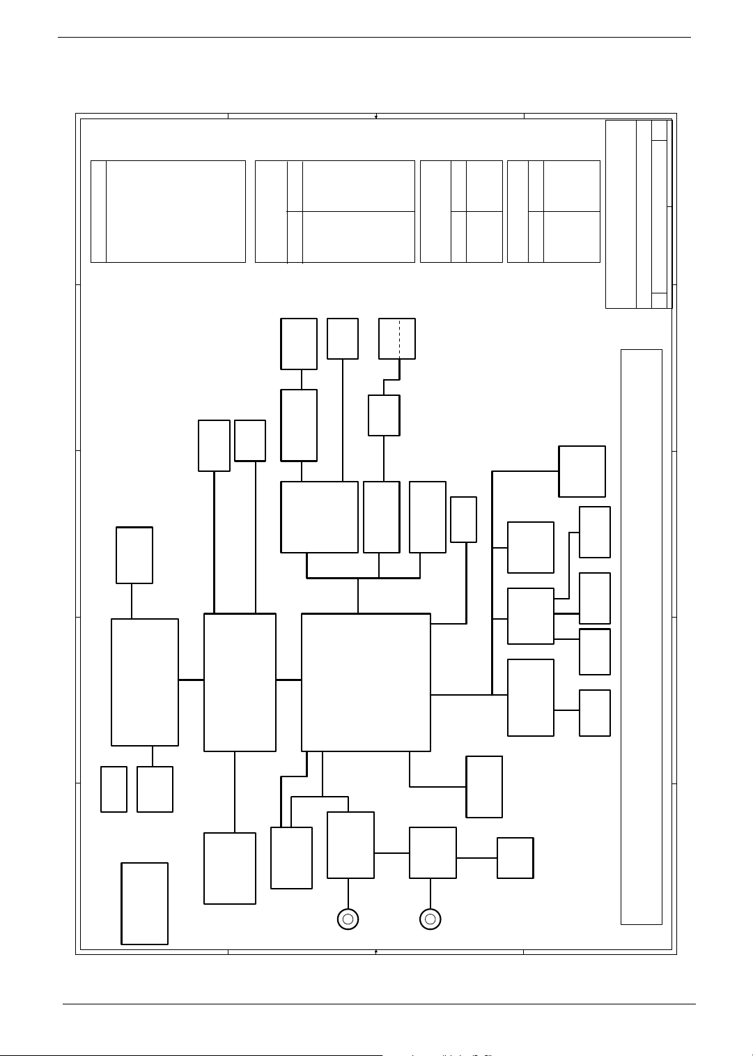
System Block Diagram
SC
E
PCB LAYER
L1:COMPONENT
L2:GND
D
Project Code : 91.47I01.001
Skylark II - SC
C
IMVP IV
(INTERSIL)
L5:SIGNAL2
L4:VCC
L3:SIGNAL1
04. 21.~ 2004-SA
05. 23.~ 2004-SB
06. 29.~ 2004-SC
38
ISL6218
L7:GND
L6:SIGNAL3
L8:COMPONENT
13
CRT
CONN
RGB
5V_S5
OUTPUTS
MAX1999/MAX1909
Switching Power
DC/DC&CHARGER
14
LCD
DCBATOUT
INPUTS
2121
PCMCA
SLOT*1
(TI)
Power Switchs
TSP2220
LVDS
3D3V_S5
1D5V_S5
5V_S3
3D3V_S3
21
1394
CONN*1
19,20
(TI)
PCI7420
Cardbus+1394
5V_S0
VCC_IO_S0
3D3V_S0
TXFM
(LANCOM)
LAN
PAGE: 39
BT+
PAGE:34,36,37
AD+
23
RJ45
RJ11
23
LF-H80P
22
(REALTEK)
RTL8100CL
38
OUTPUTS
CPU_CORE_S0
VCC_CORE_S0
ISL6218
CPU DC/DC
MiniPCI
DCBATOUT
Switching Power
INPUTS
18
24
USB*2
802.11a/b
35,37
MAX1845
OTHER DC/DC
FWH
49LF004A
2D5V_S3
1D5V_S0
OUTPUTS
DCBATOUT
INPUTS
32
1D2V_S0
1D25V_S0
LPC
DEBUG
VCC_IO_S0
Acer Incorporated
8F, 88, Sec.1, Hsin Tai Wu Rd., Hsichih,
Taipei Hsien 221, Taiwan, R.O.C.
Title
32
CONN.
3333
INT KB
of
142Tuesday, July 20, 2004
E
Skylark II
Block Diagram
A3
Size Document Number Rev
Date: Sheet
27
D
LINE INPS2CRT PRINTER LINE OUTRJ45 MICUSB*2AC IN
C
15,16,17
ATA100
26
(GMT)
G1421B
OP AMP
Line Out
2 2
USB
LPC BUS
28
HDD
PCI BUS
5,6
400MHz
B
Dothan
Mobile CPU
31
ITP
CPU Thermal
MAX6509
A
ICS
CLK GEN.
4
pull-H/L
3
950810CG
4 4
HOST BUS
DDR SDRAM
200/266 MHZ
7,8,9
66MHz
HUB I/F
Montara-GM
(855GM)
AC-LINK
USB
24
10,11,12
MDC
SO-DIMM*2
(Bluetooth)
3 3
ICH4-M
25
ALC655
AC'97
CODEC
(REALTEK)
MIC IN
KBC
M38857M8
(MITSUBISHI) (SST)
(NS)
NS SIO
PC87392
26
SPEAKER
33
29
TOUCH
PAD
31
G768D(GMT)
Van Cntl
Temp
Sensor
30
FIR
TFDU6102
(VISHAY)
1 1
Port Replicator (100 PIN)
B
PORT
SEARIAL
A
2 Chapter 1
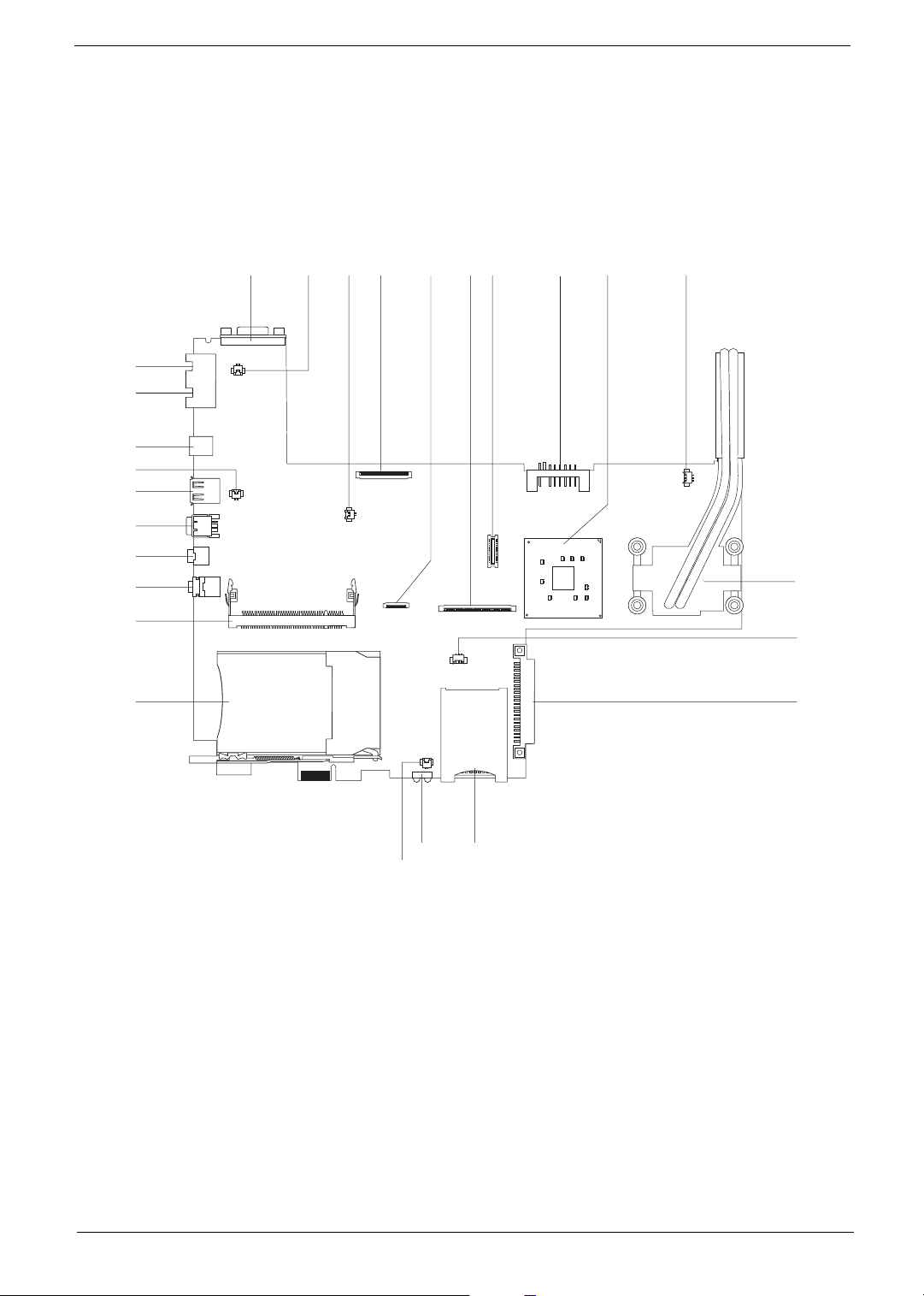
Board Layout
Top View
NOTE: The board layout is not ready as the service guide released. The board views (bot top and bottom) in
this chapter are for TravelMate 370. We will update the service guide as soon as we get the main board
layout.
26
25
24
23
22
21
20
19
18
17
12
3
5
4
67 9
8
10
11
12
13
15
14
16
1 External Display Port 14 3-in1 Card Reader Slot
2 Modem Cable Connector 15 Infrared Port
3 Speaker Connector 16 Microphone Connector
4 LCD FPC Connectors 17 PCMCIA Slot
5 Touchpad Board Connectors 18 Mini-PCI Slot
6 Keyboard Connector 19 Microphone/Line-in Jack
7 Modem Board Connector 20 Headphone/Speaker/Line-out Jack
8 Battery Connector 21 IEEE 1394 Port
9 North Bridge 22 USB Port
10 Fan Connector 23 Cover Switch Connector
11 CPU 24 DC-In
12 RTC Battery Connector 25 RJ45 Ethernet Connector
Chapter 1 3
13 HDD Connector 26 RJ11 Modem Connector
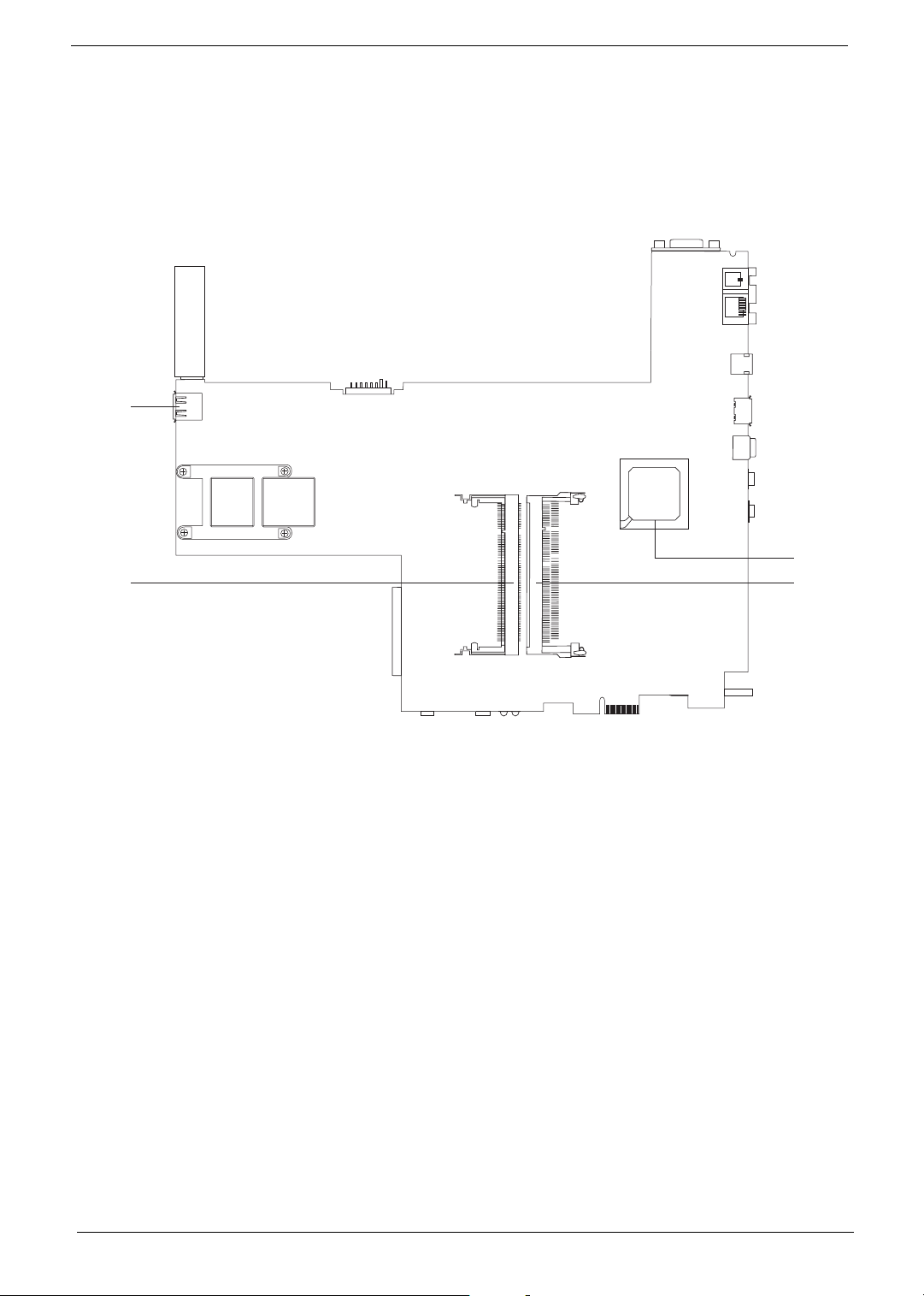
Bottom View
4
3
1
2
1 South Bridge 3 DIMM Slot
2 DIMM Slot 4 USB port
4 Chapter 1
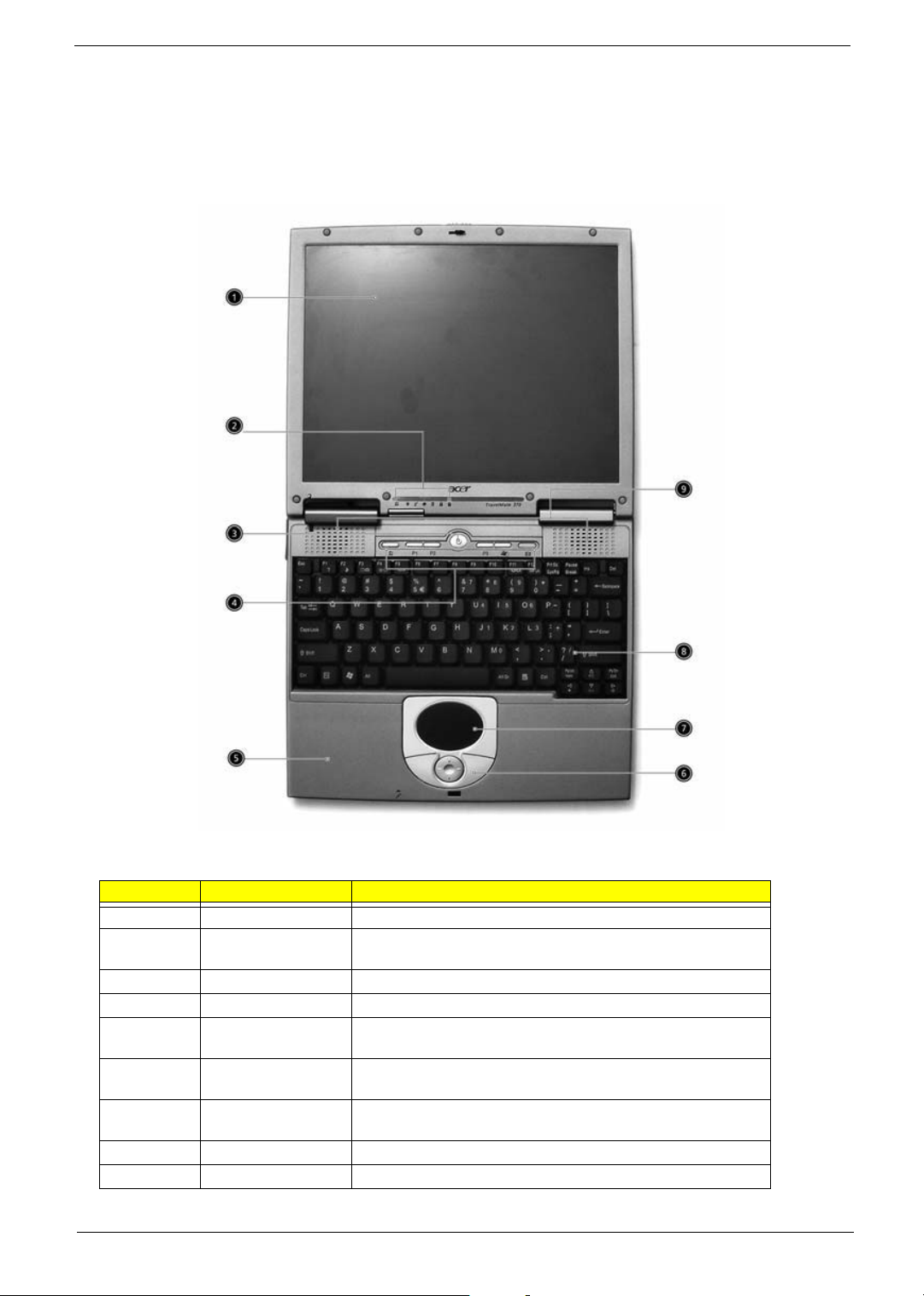
Outlook View
A general introduction of ports allow you to connect peripheral devices, as you would with a desktop PC.
Open front view
# Item Description
1 Display screen Also called LCD (Liquid Crystal Display), displays computer output.
2 Status indicators LEDs (Light Emitting Diode) that turn on and off to show the status
of the computer and its components.
3 Power button Turns the computer on and off.
4 Launch keys Two special keys for frequently used programs.
5 Palmrest Comfortable support area for your hands when you use the
6 Click buttons (left,
center and right)
7 Touchpad Touch-sensitive pointing device which functions are like a computer
8 Keyboard Inputs data into your computer.
9 Speaker Outputs sound.
computer.
The left and right button functions are like the left and right mouse
buttons; the center button serves as a 4-way scroll button.
mouse.
Chapter 1 5
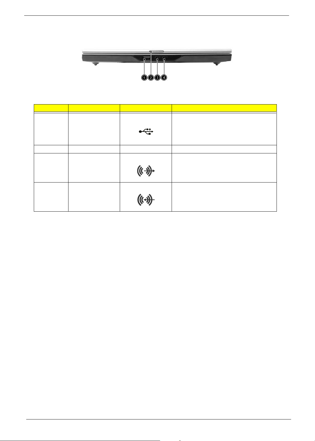
Front View
# Item Icon Description
1 USB 2.0 port Connects to Universal Serial Bus devices (e.g.
2 Latch Latch for opening and closing the computer.
3 Headphone/Speaker/
Line-out (SPDIF) jack
USB mouse, USB camera).
Connects to headphones or other line-out audio
devices (speaker).
4 Microphone/Line-in
jack
Accepts input from external microphones.
6 Chapter 1
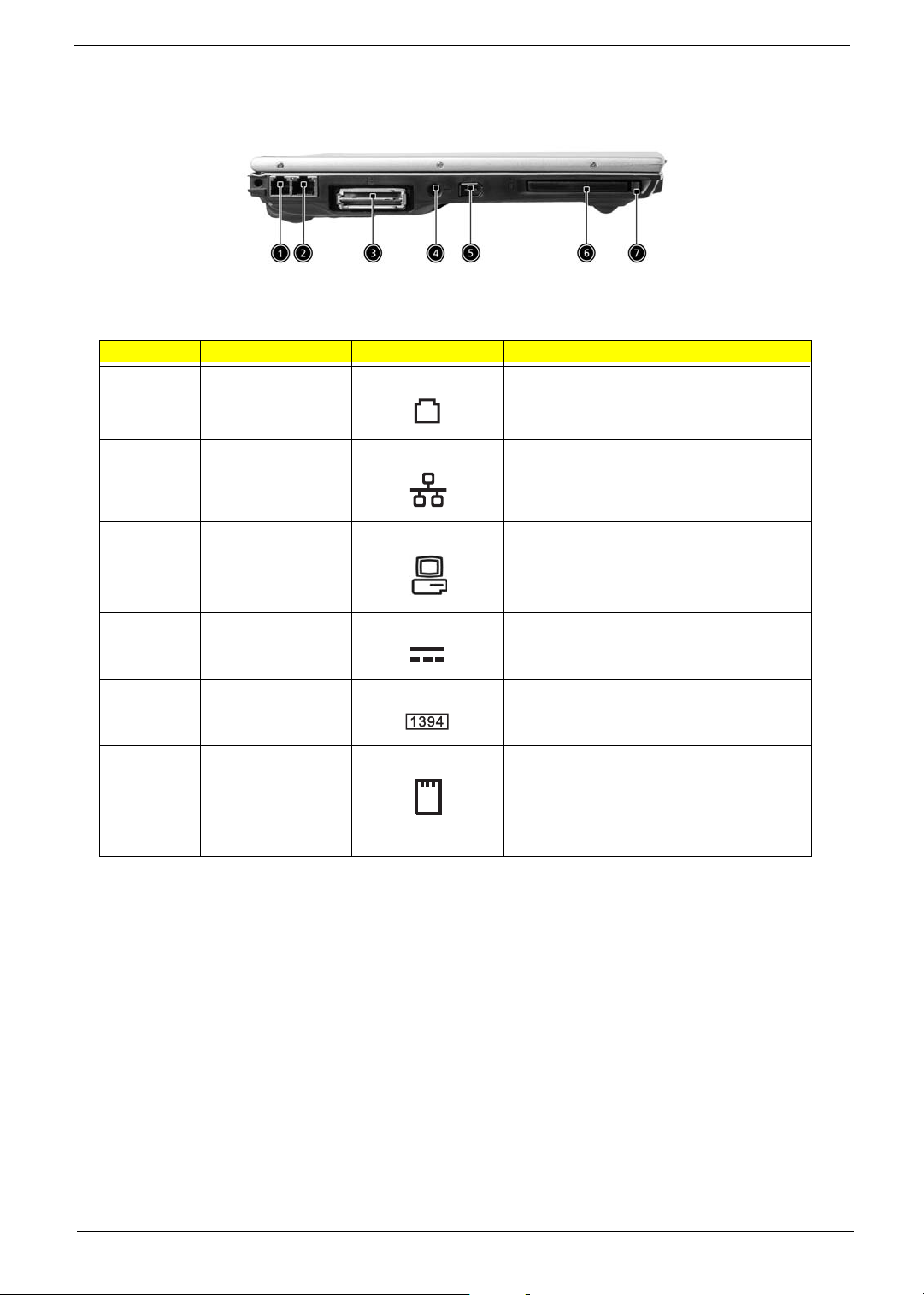
Left view
# Item Description
1 Modem port Connects to a phone line.
2 Ethernet port Connects to an Ethernet 10/100-based network.
3 EasyPort Connects to Acer EasyPort or I/O port replicator.
4 DC-in jack Connects the AC adapter.
5 IEEE 1394 port Connects to IEEE 1394 devices.
6 PC Card slot Accepts one Type II 16-bit PC Card or 32-bit
CardBus PC Card.
7 Eject button Eject the PC Card from the slot.
Chapter 1 7
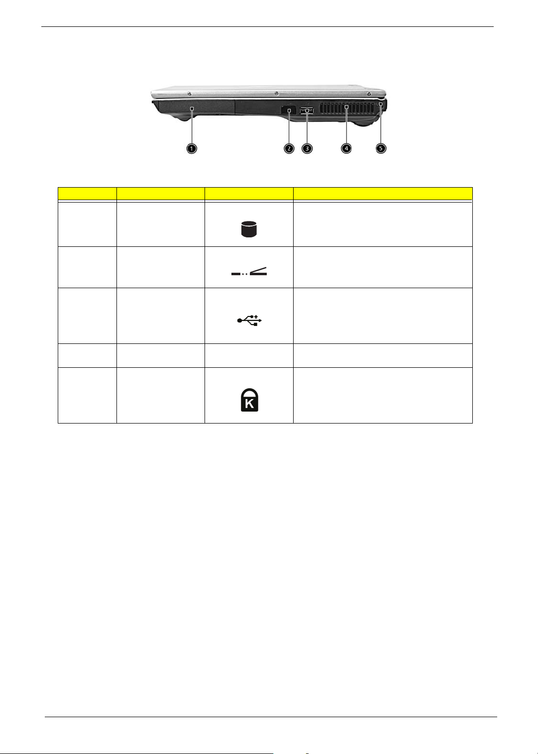
Right view
# Item Icon Description
1 HDD Houses the computer’s hard disk.
2 Infrared port Connects to Universal Serial Bus devices (e.g.,
USB mouse, USB camera).
3 USB 2.0 ports Connects to Universal Serial Bus devices (e.g.,
4 Ventilation slot Enable the computer to stay cool, even after
5 Security keylock Connects to a Kensington-compatible computer
USB mouse, USB camera).
prolonged use.
security lock.
8 Chapter 1
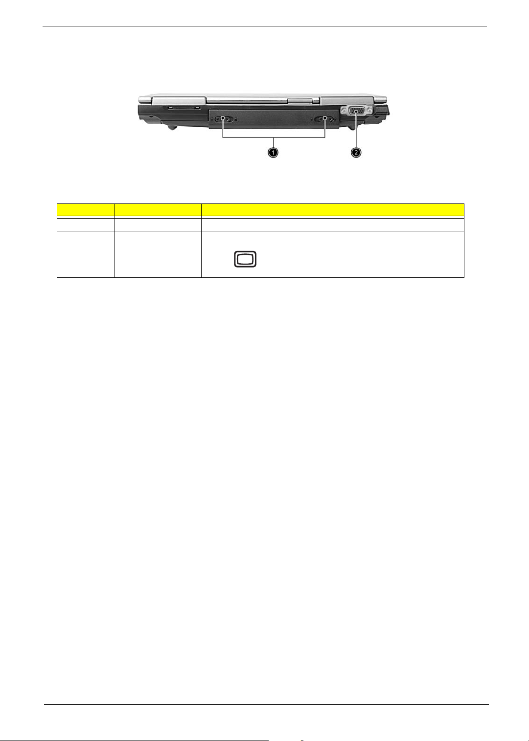
Rear view
# Item Description
1 Battery release latch Unlatches the battery to remove the battery pack.
External display port Connects to a display device (e.g., external
monitor, LCD projector) and displays up to 16.7
million colors with 2048 x 1536 pixel resolution.
Chapter 1 9
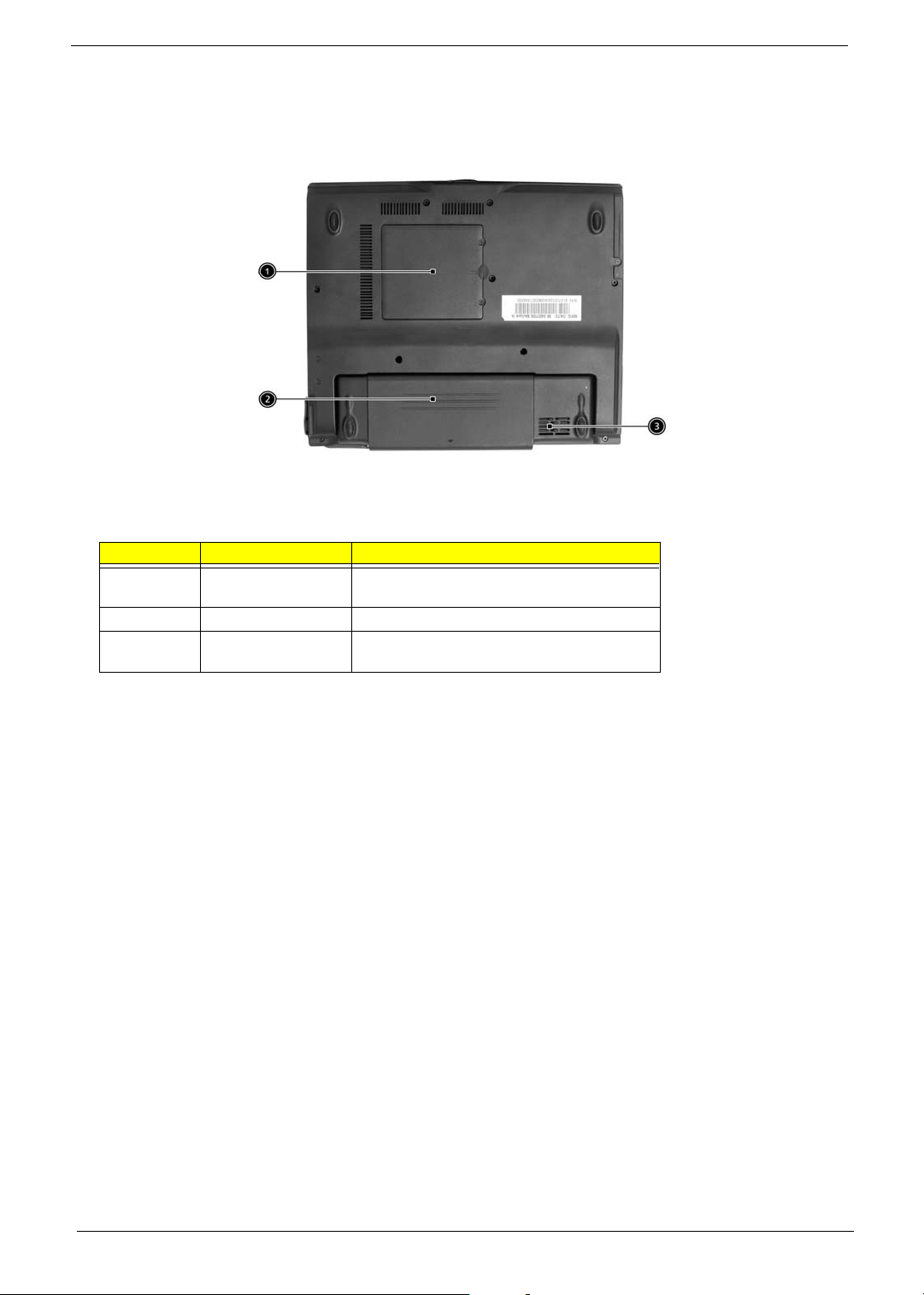
Bottom Panel
# Item Description
1 Memory compartment This compartment houses the computer’s main
2 Battery bay Houses the computer’s battery pack.
3 Ventilation slot Enables the computer to stay cool, even after
memory.
prolonged use.
10 Chapter 1
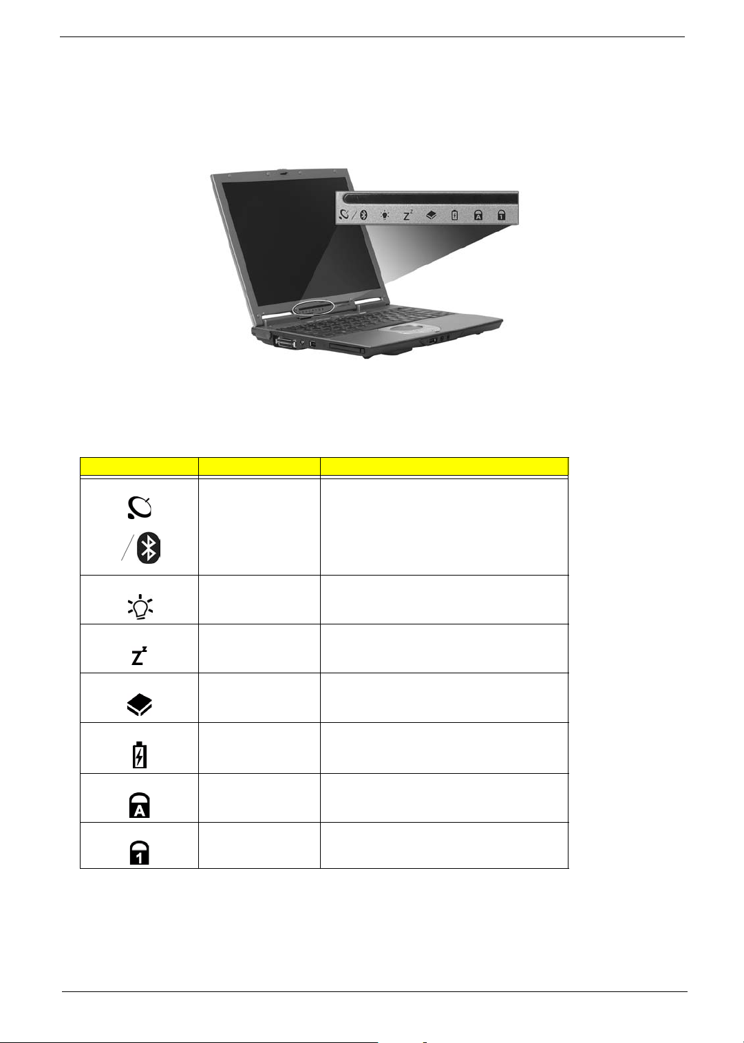
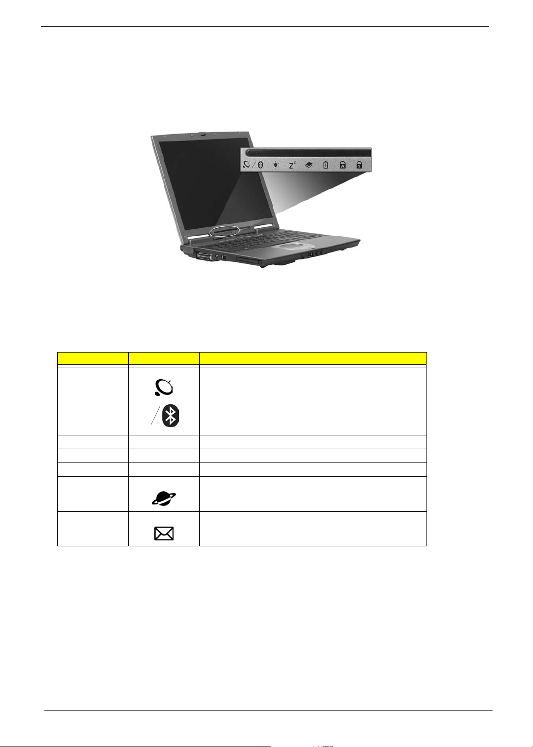
Indicators
The computer has seven easy-to-read status indicators on the display screen and three on the LCD panel.
The Wireless, Power and Sleep status indicators are visible even when the display is closed.
Icon Function Description
InviLink
TM
/Bluetooth®
Orange indicates that wireless LAN is enabled.
Blue indicates that Bluetooth® is enabled.
Power mode Lights green when power is on and standby
mode.
Sleep Lights when the computer enters standby mode
and blinks when it enters into or resumes from
hibernation mode.
Media activity Lights when the floppy drive, hard disk drive or
Battery charge Lights when the battery is being charged.
Caps lock Lights when Caps Lock is activated.
Num lock Lights when Num Lock is activated.
optical drive is active.
Chapter 1 11
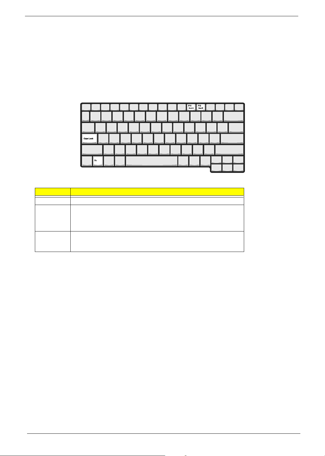
Keyboard
The keyboard features full-size keys with an embedded keypad, separate cursor control keys, two Windows
keys, and twelve function keys.
Special keys
Lock keys
The keyboard has three lock keys which you can toggle on and off.
Lock Key Description
Caps Lock When Caps Lock is on, all alphabetic characters are typed in uppercase.
Num lock
(Fn-F11)
Scroll lock
(Fn-F12)
When Num Lock is on, the embedded numeric keyboard can be used. The keys
function as a calculator (complete with the arithmetic operator +, -, *, and /). Use
this mode when you need to do a lot of numeric data entry. A better solution
would be to connect an external keypad.
When Scroll Lock is on, the screen moves one line up or down when you press
the up or down arrow keys respectively. Scroll Lock does not work with some
applications.
12 Chapter 1
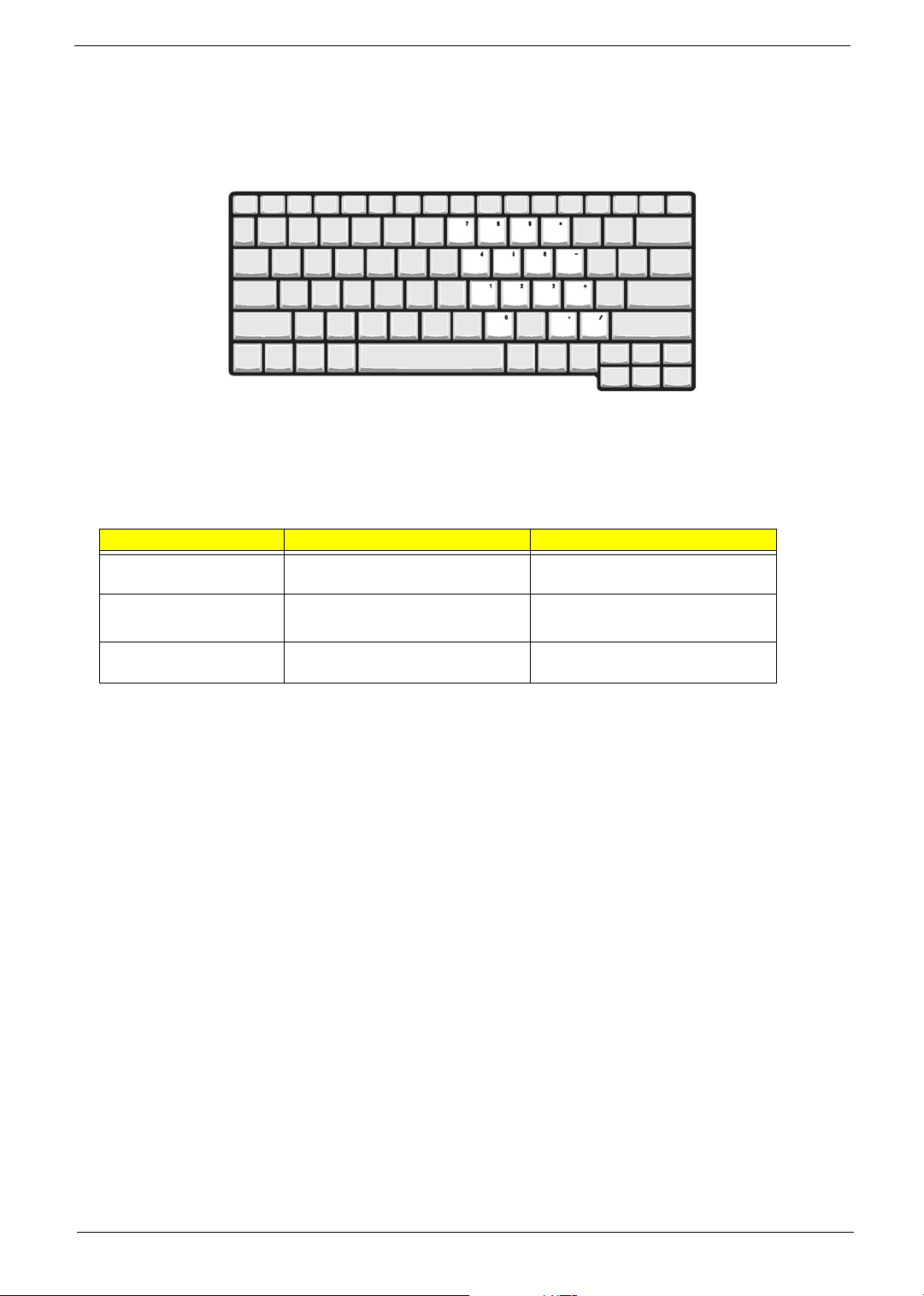
Embedded Keypad
The embedded keypad functions like a desktop numeric keypad. It is indicated by small characters located on
the upper right corner of the keycaps. To simplify the keyboard legend, cursor-control key symbols are not
printed on the keys.
To use the embedded numeric keys, toggle the Num Lock on by pressing the Fn + F11 keys simultaneously.
With the embedded keypad turned on, the following actions are possible:
Desired Access Num Lock On Num Lock On
Number keys on embedded
keypad
Cursor-control keys on
embedded keypad
Main keyboard keys Hold Fn key while typing letters on
Type numbers in the normal manner.
Hold
jwhile using cursor-control
keys.
embedded keypad.
Hold Fn key while using cursor-control
keys.
Type the letters in the normal manner.
NOTE: If an external keyboard or keypad is connected to the computer, the Num Lock feature automatically
shifts from the internal keyboard to the external keyboard or keypad.
Chapter 1 13
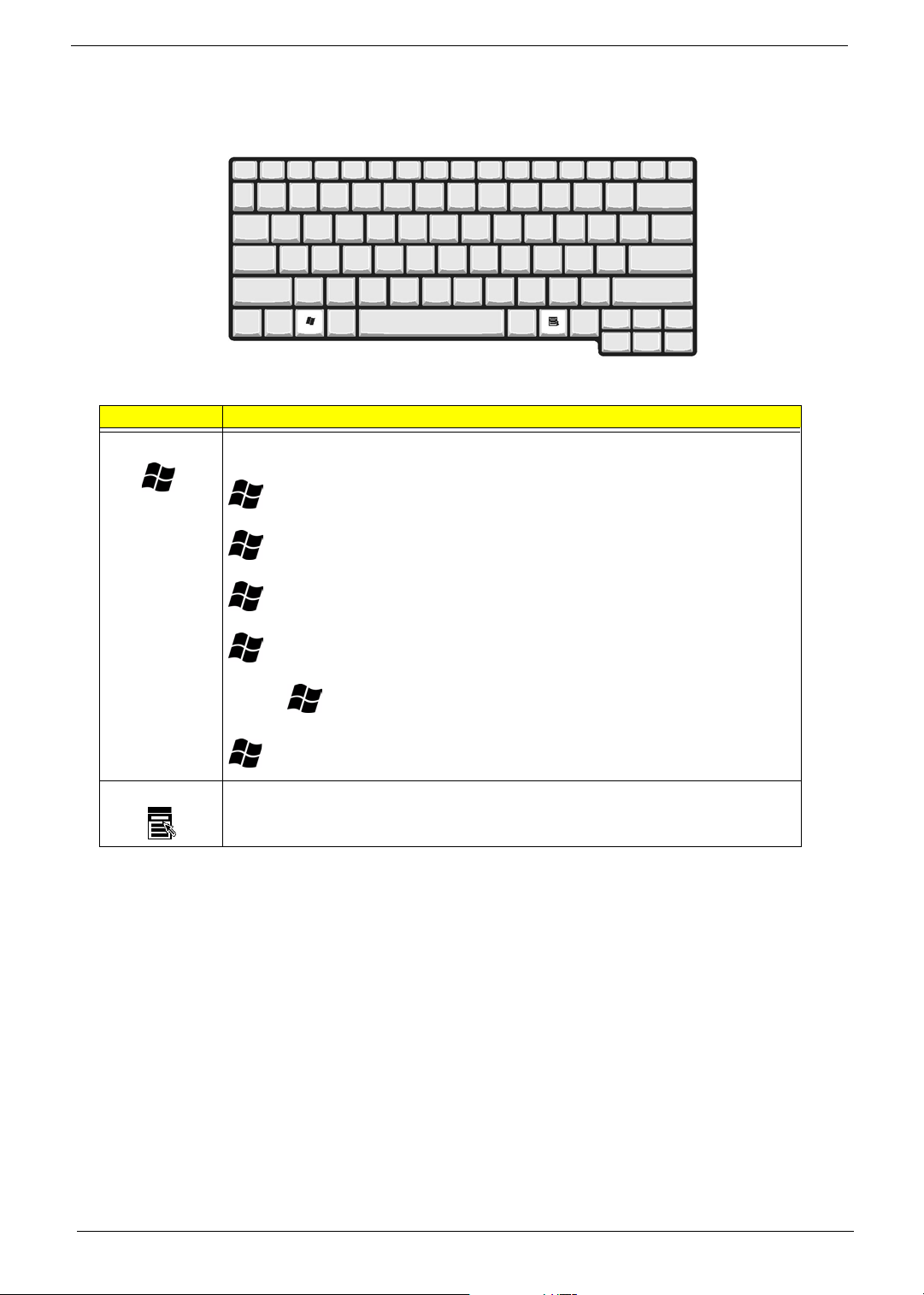
Windows Keys
The keyboard has two keys that perform Windows-specific functions.
Key Description
Windows logo key Pressed alone, this key has the same effect as clicking on the Windows Start button; it
launches the Start menu. It can also be used with other keys to provide a variety of functions:
+ Tab (Activates the next Taskbar button)
+ E (Explores the My Computer)
+ F (Finds Document)
+ M (Minimizes all windows)
j + + M (Undoes the minimize all windows action)
+ R (Displays the Run... dialog box)
Application key This key has the same effect as clicking the right mouse button; it opens the application’s
context menu.
14 Chapter 1
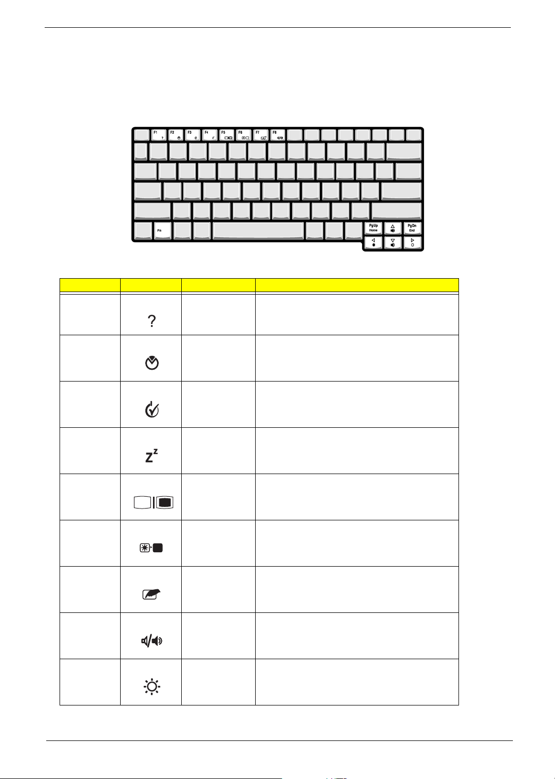
Keyboard Hot keys
The computer employs hot keys or key combinations to access most of the computer’s controls like screen
brightness, volume output and the BIOS utility.
To activate a keyboard hot key, press and hold the Fn key before pressing the other key(s) in the hot key
combination.
Hot Key Icon Function Function
Fn +
l
Hot key help Displays help on hot keys.
Fn +
Fn +
Fn +
Fn +
Fn +
Fn +
Fn +
m
n
o
p
q
r
s
Setup Access the computer’s configuration utility.
Power
management
scheme toggle
Sleep Puts the computer in Sleep mode, which can be
Display toggle Switches display output between the display screen,
Screen blank Turns the display screen backlight off to save power.
Touchpad toggle Turns the internal touchpad on and off.
Speaker on/off Turns the speaker on and off.
Switches the power management scheme used by the
computer (function available if supported by operating
system).
defined.
external monitor (if connected) and both the display
screen and external monitor.
Press ant key to return.
x
Fn +
Chapter 1 15
Brightness up Increases the screen brightness.

Hot Key Icon Function Function
Fn + z
Brightness down Decreases the screen brightness.
Fn +
Fn +
w
y
Volume up Increases the speaker volume.
Volume down Decreases the speaker volume.
16 Chapter 1

Euro key
If your keyboard layout is set to United States-International or United Kingdom or if you have a keyboard with a
European layout, you can type the Euro symbol on your keyboard.
NOTE: For US keyboard users: The keyboard layout is set when you first set up Windows. For the Euro
symbol to work, the keyboard layout has to be set to United States-International.
To verify the keyboard type in Windows Millennium Edition and Windows 2000, follow the steps below:
1. Click on Start, Settings, Control Panel.
2. Double-click on Keyboard.
3. Click on the Language tab.
4. Verify that the keyboard layout used for "En English (United States)" is set to United States-International.
If not, select and click on Properties; then select United States-International and click on OK.
5. Click on OK.
To verify the keyboard type in Windows XP, follow the steps below:
1. Click on Start, Control Panel.
2. Double-click on Regional and Language Options.
3. Click on the Language tab and click on Details.
4. Verify that the keyboard layout used for "En English (United States)" is set to United States-International.
If not, select and click on ADD; then select United States-International and click on OK.
5. Click on OK.
To type the Euro symbol:
1. Locate the Euro symbol on your keyboard.
2. Open a text editor or word processor.
3. Hold Alt Gr and press the Euro symbol.
NOTE: Some fonts and software do not support the Euro symbol. Please refer to www.microsoft.com/
typography/faq/faq12.htm for more information.
Chapter 1 17
Launch Keys
Located above the keyboard are six buttons. These buttons are special one-click buttons that perform special
functions.
Launch key Icon Description
Wireless This button permits user Enabled/Disabled Wireless LAN
network and Bluetooth
P1 User-programmable
P2 User-programmable
P3 User-programmable
Web browser Launch Internet Explorer (or user-defined program).
Mail Launch Outlook Express (or user-defined program).
® options.
18 Chapter 1
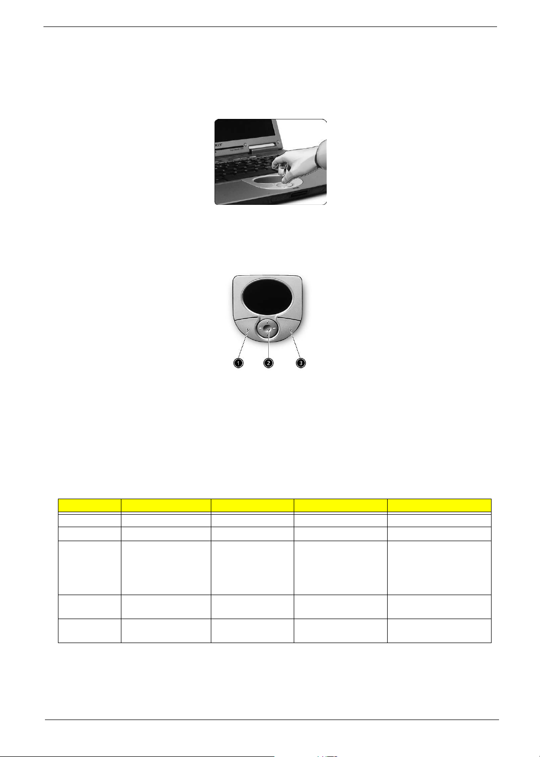
Touchpad
The built-in touchpad is a pointing device that senses movement on its surface. This means the cursor
responds as you move your finger on the surface of the touchpad.
The central location on the palmrest provides optimum comfort and efficiency.
Touchpad Basics
The following items teach you how to use the touchpad:
T Move your finger across the touchpad to move the cursor.
T Press the left (1) and right (3) buttons located on the edge of the touchpad to do selection and
execution functions. These two buttons are similar to the left and right buttons on a mouse.
Tapping on the touchpad produces similar results.
T Use the 4-way scroll (2) button to scroll a page up, down, left or right. This button mimics your
cursor pressing on the vertical and horizontal scroll bards of Windows applications.
Function Left Button Right Button 4-way Scroll Button Tap
Execute Click twice quickly Tap twice quickly
Select Click once Tap once
Drag Click and hold. Then
slide your finger
across the touchpad
to drag the cursor
over the selection.
Access
context menu
Scroll Click and hold the up/
Click once
down/ left/ right button
Tap twice quickly. On the
second tap, slide your
finger across the
touchpad to drag the
cursor over the selection.
NOTE: A. Keep your fingers dry and clean when using the touchpad. Also keep the touchpad dry and clean.
The touchpad is sensitive to your finger movements: the lighter your touch, the better the response.
Tapping harder will not increase the touchpad’s responsiveness. B. When using an external USB
mouse, you can press Fn+
r to disable the touchpad.
Chapter 1 19
Hardware Specifications and Configurations
Processor
Item Specification
CPU type Intel® Pentium® M 715 ~ 755 (1.5/1.6/1.7/1.8/1.9/2.0 GHz, 400FSB MHz)
or higher
Core logic Intel® Pentium® M 715 ~ 755+Intel® 855 GME
CPU package Micro-FCBGA
CPU core voltage 0.95V ~ 1.420V
BIOS
Item Specification
BIOS vendor Phoenix
BIOS Version 1.0
BIOS ROM type Flash ROM
BIOS ROM size 512KB
BIOS package PLCC
Supported protocols ACPI 1.0b, APM 1.2, PC Card 95, AC97 2.1, EPP/IEEE 1284, ECP/IEEE
1284 1.7 & 1.9, PCI 2.2, PnP 1.0a, DMI 2.0, USB, DDC-2B, ODD bootable,
Windows keyboard Microsoft Simple Boot Flag
BIOS password control Set by setup manual
Second Level Cache
Item Specification
Cache controller Built-in CPU
Cache size 2MB
1st level cache control Always enabled
2st level cache control Always enabled
Cache scheme control Fixed in write-back
System Memory
Item Specification
Memory controller Intel 855GM
Onboard memory size 0MB
DIMM socket number 2 sockets (4 banks)
Supports memory size per socket 128M / 256M / 512M / 1024MB(1GB)
Supports maximum memory size 2048MB (2GB)
Supports DIMM type DDR SDRM (Double Data Rate-Synchronous Dynamic Random Access
Memory)
Supports DIMM Speed 266MHz
Supports DIMM voltage 2.5V
Supports DIMM package 200-pin SODIMM
Memory module combinations You can install memory modules in any combinations as long as they
match the above specifications.
20 Chapter 1
Memory Combinations
Slot 1 Slot 2 Tot a l Memory
128 / 256 / 512 / 1024MB 0 MB 128 / 256 / 512 / 1024MB
128 / 256 / 512 / 1024MB 128MB 256 / 384 / 640 / 1152MB
128 / 256 / 512 / 1024MB 256MB 384 / 512 / 768 / 1280MB
128 / 256 / 512 / 1024MB 512MB 640 / 768 / 1024 / 1536MB
128 / 256 / 512 / 1024MB 1024MB 1152 / 1280 / 1536 / 2048MB
Above table lists some system memory configurations. You may combine DIMMs with various capacities to
form other combinations.
.
LAN Interface
Item Specification
Chipset Realtek RTL8100
Supports LAN protocol 10/100 Mbps
LAN connector type RJ45
LAN connector location Left side
PXE version 2.0
Wireless LAN Interface
Item Specification
Chipset Intel PRO/Wireless 2200
Supports LAN protocol 802.11b/g
Data Throughput 11M~54M bps
Modem Interface
Item Specification
Chipset Agere
Fax modem data baud rate (bps) 14.4K
Data modem data baud rate (bps) 56K
Supports modem protocol V.90 / V.92 MDC
Modem connector type RJ11
Modem connector location Left side
Hard Disk Drive Interface
Item
Vendor &
Model
Name
Capacity
(MB)
Bytes per
sector
Data heads 2 3 3 4
Drive Format
Disks 1 2 2 2
HGST 40GB
(IC25N040ATMR
04) CASCADE
40000 40000 60000 60000
512 512 512 512
TOSHIBA
40GB(MK4021G
AS) NEPTUNE
HGST
60G(IC25N060A
TMR04),
CASCADE
TOSHIBA
60GB(MK6021G
AS) NEPTUNE
Chapter 1 21
Hard Disk Drive Interface
Item
Spindle
speed
(RPM)
Performance Specifications
Buffer size 2048KB 2048KB 8192KB 2048KB
Interface ATA-6 ATA- 5 ATA- 6 ATA-5
Max. media
transfer
rate (diskbuffer,
Mbytes/s)
Data
transfer
rate
(host~buffe
r, Mby tes /
s)
DC Power Requirements
Voltage
tolerance
4200RPM 4200RPM 4200RPM 4200RPM
350 298 350 298
100 MB/Sec.
Ultra DMA mode5
5V(DC) +/- 5% 5V(DC) +/- 5% 5V(DC) +/- 5% 5V(DC) +/- 5%
100 MB/Sec.
Ultra DMA mode5
100 MB/Sec.
Ultra DMA mode5
100 MB/Sec.
Ultra DMA mode5
Audio Interface
Item Specification
Audio Controller Realteck ALC655
Audio onboard or optional Built-in
Mono or Stereo Mono
Resolution 20 bit stereo Digital to Analog converter
18 bit stereo Analog to Digital converter
Compatibility Microsoft PC98/PC99, AC97 2.1
Mixed sound source Microphone, CD, AUX
Sampling rate 48 kHz
Internal microphone Yes
Internal speaker / Quantity Yes
Supports PnP IRQ IRQ10
Video Interface
Item Specification
Chip vendor Intel
Chip name 855GM (Integrated with Northbridge)
Supports ZV (Zoomed Video) port No
Graph interface Inside 855GM (Accelerated Graphics Port) Bus
Maximum resolution (LCD) 1024*768
Maximum resolution (CRT) 1600*1200
Video Memory
Item Specification
Fixed or upgradeable Fixed
22 Chapter 1
Video Memory
Item Specification
Video memory size 64MB (Share system memory)
IEEE 1394 Port
Item Specification
IEEE 1394 controller TI PCI 7420
Access location Left side
USB Port
Item Specification
USB Compliancy Level 2.0
EHCI USB 2.0
Number of USB port 2
Location Front and right side
Serial port function control Always Enabled
PCMCIA Port
Item Specification
PCMCIA controller TI PCI 7420
Supports card type Type II
Number of slots One
Access location Left side
Supports ZV (Zoomed Video) port No ZV support
Supports 32 bit CardBus Yes (IRQ10)
System Board Major Chips
Item Controller
System core logic Intel 855GM
Super I/O controller NS PC87392
Audio controller Realtek ALC655
Video controller Intel 855GM
Hard disk drive controller Intel ICH4-M
Keyboard controller Mitsubishi M38857M8
RTC Intel ICH4-M
IEEE 1394 TI PCI 7420
PCMCIA TI PCI 7420
Keyboard
Item Specification
Keyboard controller Mitsubishi M38857M8
Keyboard vendor & model name Darfon
Total number of keypads 84-/85-/88-key
Windows keys Yes
Chapter 1 23
Keyboard
Item Specification
Internal & external keyboard work simultaneously 1. Plug USB keyboard to the USB port directly: Yes
2. Use port replicator then plug a USB/PS 2 keyboard to the
USB port/PS 2 port on the port replicator: Yes
Battery
Item Specification
Vendor & model name Simplo
Battery Type Li-ion
Pack capacity 2200mAh
Cell voltage 3.7 V/cell
Number of battery cell 6
Package configuration 3 cells in series, 2 series in parallel
Package voltage 11.1V/6cell
LCD
Item Specification
Vendor & model name IDT/IAXG01W
IDT/IAXG02L
TOSHIBA/LTM12C505W
LCD display area (diagonal, inch) 12.1
Display technology TFT
Resolution XGA (1024X768)
Screen Diagonal [mm] 307
Active Area [mm] 245.76(H) x 184.32(V)
Pixel Pitch [mm] 0.080(per one triad) x 0.240
Pixel Arrangement R,G,B Vertical Stripe
Weight [grams] 290 Typ.
Physical Size [mm] 261.0(W) x 198.0(H) x 5.0(D) Typ.
Support Color Native 262K colors(RGB 6-bit data driver)
White Luminance [cd/m2]
Design Point 1:(ICFL=3.5mA)
Design Point 2:(ICFL=6.5mA)
Contrast Ratio 250 : 1 Typ.
Optical Rise Time/Fall Time [msec] 30Typ.,50 MAX.
Nominal Input Voltage VDD [Volt] +3.3 Typ.
Power Consumption [Watt]
(VDD Line)
(VCFL Line)
Electrical Interface 4 pairs, single LVDS
Temperature Range [degree C]
Operating
Storage (Shipping)
95 Typ. (center), 90 Typ. (5 points average)
160 Typ. (center),150 Typ. (5 points average)
1.2 Typ.
3.5 Typ.
0 to +50
-20 to +60
24 Chapter 1
 Loading...