

Page 1

Altos S205F / S200F
Tower Kit
Installation Guide
Issue 1.0
1 May, 2004
Page 2

Altos S205F / S200F Tower Kit Installation Guide
Notices
Changes may be made periodically to the information in this publication without obligation to
notify any person of such revision or changes. Such changes will be incorporated in new editions
of this manual or supplementary documents and publications. This company makes no
representations or warranties, either expressed or implied, with respect to the contents hereof
and specifically disclaims the implied warranties of merchantability or fitness for a particular
purpose.
No part of this publication may be reproduced, stored in a retrieval system, or transmitted, in any
form or by any means, electronic, mechanical, photocopy, recording, or otherwise, without the
prior written permission of Acer Incorporated.
Issue 1.0 1 May, 2004
Contents
• Introduction
•Safety
• Tools Required
• Tower Installation Kit
•Procedure
ii
Page 3
Altos S205F / S200F Tower Kit Installation Procedure
Altos S205F / S200F Tower Kit Installation
Introduction
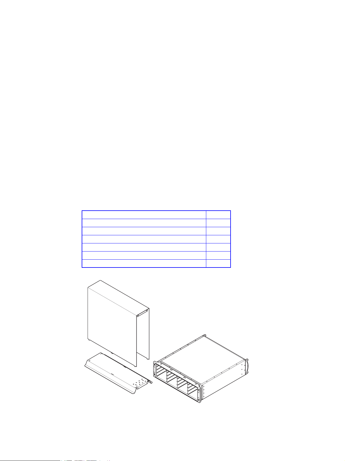
This document defines the installation procedure for converting the Altos S205F / S200F Rack
Enclosure storage system to a Tower system. The unpopulated enclosure and tower installation kit
are shown in Figure 1.
Safety
Warning An Enclosure can weigh up to 37kg (81lb). Do not try to lift it by yourself.
Tools Required
• Pozidrive screwdriver
(not supplied)
Tower Installation Kit
Description Quantity
Tower Foot 1
Tower Cover 1
M5 Lock Washer 4
M5 Plain Washer 4
M5 x 16 Pan Head, POZI Screw 4
M5 x 8 Pan Head, POZI Screw with Patchlock 4
Figure 1: Tower Installation Kit with Unpopulated Enclosure
1
Page 4

Altos S205F / S200F Tower Kit Installation Procedure
Procedure
Important The enclosure must be unpopulated before you begin the tower installation. Please refer to Altos
S205F / S200F User’s Manual for details of module removal/replacement procedures.
1 Remove the four bezel screw covers from the front of the enclosure chassis (if fitted).
2 Place the unpopulated enclosure on the tower foot, ensuring that the drive carrier connectors are
on the left hand side of the drive bay when viewed from the front of the enclosure, see Figure 2.
Note: The drive carrier handle will open from the top when the drive carrier is inserted
correctly.
TOPTOP
Drive carrier connectors
on left side of Bay
Figure 2: Drive Connector Locations
2
Page 5

Altos S205F / S200F Tower Kit Installation Procedure
3 Secure the front of the enclosure to the tower foot using:
– 2 off M5 x 16 pan head POZI screws
– 2 off M5 plain washer
– 2 off lock washer
(refer to Figure 3)
4 Secure the rear of the enclosure to the tower foot using:
– 2 off M5 x 8 pan head POZI screws with patchlock
(refer to Figure 3)
Figure 3: Securing the Enclosure to the Foot
3
Page 6

Altos S205F / S200F Tower Kit Installation Procedure
5 Slide the tower cover over the enclosure, taking care to align the tabs on the cover with the slots
in the foot.
Caution Failure to align the tabs on the cover with the slots in the foot during assembly may result in
damage to the paintwork on the foot.
The three location tabs on each side of the tower cover must locate in the three corresponding slots
on each side of the tower foot, as shown in Figure 4.
Tabs
Slots
Figure 4: Locating the Tower Cover on the Foot
4
Page 7

Altos S205F / S200F Tower Kit Installation Procedure
6 Secure the tower cover to the front of the enclosure using:
– 2 off M5 x 16 pan head POZI screws
– 2 off M5 plain washer
– 2 off lock washer
through the two holes at the top of the enclosure.
(refer to Figure 5)
7 Secure the tower cover to the rear of the enclosure using:
– 2 off M5 x 8 pan head POZI screws with patchlock
(refer to Figure 5)
Figure 5: Securing the Cover
8 Refit the bezel covers over the four securing screws at the front of the enclosure chassis
9 Refit the modules in the enclosure in accordance with the instructions in Altos S205F / S200F User’s
Manual.
5
Page 8

Altos S205F / S200F Tower Kit Installation Procedure
Figure 6: Populated Tower Installation
END OF PROCEDURE
6
 Loading...