

Page 1

Acer Altos R310
User’s Guide
Page 2

Copyright © 2004 Acer Incorporated
All Rights Reserved.
Acer Altos R310
User’s Guide
1st Issue: March 2004
Changes may be made periodically to the information in this publication without obligation
to notify any person of such revision or changes. Such changes will be incorporated in new
editions of this manual or supplementary documents and publications. This company makes
no representations or warranties, either expressed or implied, with respect to the contents
herein and specifically disclaims the implied warranties of merchantability or fitness for a
particular purpose.
Record the model number, serial number, purchase date, and place of purchase information in
the space provided below. The serial number and model number are recorded on the label
affixed to your computer. All correspondence concerning your unit should include the serial
number, model number, and purchase information.
No part of this publication may be reproduced, stored in a retrieval system, or transmitted, in
any form or by any means, electronic, mechanical, photocopy, recording, or otherwise,
without the prior written permission of Acer Incorporated.
Model Number : _________________________________
Serial Number: ___________________________________
Purchase Date: ___________________________________
Place of Purchase: ________________________________
Acer and the Acer logo are registered trademarks of Acer Inc. Other company’s product
names or trademarks are used herein for identification purposes only and belong to their
respective companies.
Page 3

iii
Notices
FCC notice
Class A devices do not have an FCC logo or FCC IDE on the label. Class
B devices have an FCC logo or FCC IDE on the label. Once the class of
the device is determined, refer to the following corresponding
statement.
Class A equipment
This device has been tested and found to comply with the limits for a
Class A digital device pursuant to Part 15 of the FCC Rules. These limits
are designed to provide reasonable protection against harmful
interference when the equipment is operated in a commercial
environment. This device generates, uses, and can radiate radio
frequency energy, and if not installed and used in accordance with the
instructions, may cause harmful interference to radio communications.
Operation of this device in a residential area is likely to cause harmful
interference in which case the user will be required to correct the
interference at his own expense.
However, there is no guarantee that interference will not occur in a
particular installation. If this device does cause harmful interference to
radio or television reception, which can be determined by turning the
device off and on, the user is encouraged to try to correct the
interference by one or more of the following measures:
• Reorient or relocate the receiving antenna
• Increase the separation between the device and receiver
• Connect the device into an outlet on a circuit different from that
to which the receiver is connected
• Consult the dealer or an experienced radio/television technician
for help
Page 4

iv
Shielded cables
All connections to other computing devices must be made using
shielded cables to maintain compliance with FCC regulations.
Peripheral devices
Only peripherals (input/output devices, terminals, printers, etc.)
certified to comply with the Class A or Class B limits may be attached to
this equipment. Operation with noncertified peripherals is likely to
result in interference to radio and TV reception.
Caution: Changes or modifications not expressly approved by
the manufacturer could void the user’s authority, which is granted
by the Federal Communications Commission, to operate this
server.
Use conditions
This part complies with Part 15 of the FCC Rules. Operation is subject to
the following two conditions: (1) this device may not cause harmful
interference, and (2) this device must accept any interference received,
including interference that may cause undesired operation.
Canadian users
This Class A/Class B digital apparatus meets all requirements of the
Canadian Interference-Causing Equipment Regulations.
Laser compliance statement
The CD-ROM drive in this server is a laser product. The CD-ROM drive’s
classification label (shown below) is located on the drive.
CLASS 1 LASER PRODUCT
CAUTION: INVISIBLE LASER RADIATION WHEN OPEN. AVOID
EXPOSURE TO BEAM.
Page 5

Important safety instructions
Read these instructions carefully. Save these instructions for future
reference.
1 Follow all warnings and instructions marked on the product.
2 Unplug this product from the wall outlet before cleaning. Do not
use liquid cleaners or aerosol cleaners. Use a damp cloth for
cleaning.
3 Do not use this product near water.
4 Do not place this product on an unstable cart, stand, or table. The
product may fall, causing serious damage to the product.
5 Slots and openings on the back or bottom side of the chassis are
provided for ventilation; to ensure reliable operation of the
product and to protect it from overheating, these openings must
not be blocked or covered. The openings should never be blocked
by placing the product on a bed, sofa, rug, or other similar surface.
This product should never be placed near or over a radiator or
heat register, or in a built-in installation unless proper ventilation
is provided.
6 This product should be operated from the type of power indicated
on the marking label. If you are not sure of the type of power
available, consult your dealer or local power company.
7 Do not allow anything to rest on the power cord. Do not locate
this product where persons will walk on the cord.
8 If an extension cord is used with this product, make sure that the
total ampere rating of the equipment plugged into the extension
cord does not exceed the extension cord ampere rating. Also,
make sure that the total rating of all products plugged into the
wall outlet does not exceed the fuse rating.
9 Never push objects of any kind into this product through chassis
slots as they may touch dangerous voltage points or short out
parts that could result in a fire or electric shock. Never spill liquid
of any kind on the product.
10 Do not attempt to service this product yourself, as opening or
removing covers may expose you to dangerous voltage points or
other risks. Refer all servicing to qualified service personnel.
11 Unplug this product from the wall outlet and refer servicing to
qualified service personnel under the following conditions:
v
Page 6

vi
a When the power cord or plug is damaged or frayed
b If liquid has been spilled into the product
c If the product has been exposed to rain or water
d If the product does not operate normally when the operating
instructions are followed. Adjust only those controls that are
covered by the operating instructions since improper
adjustment of other controls may result in damage and will
often require extensive work by a qualified technician to
restore the product to normal condition.
e If the product has been dropped or the cabinet has been
damaged
f If the product exhibits a distinct change in performance,
indicating a need for service.
12 Replace the battery with the same type as the product's battery we
recommend. Use of another battery may present a risk of fire or
explosion. Refer battery replacement to a qualified service
technician.
13 Warning! Batteries may explode if not handled properly. Do not
disassemble or dispose of them in fire. Keep them away from
children and dispose of used batteries promptly.
14 Use only the proper type of power supply cord set (provided in
your accessories box) for this unit. It should be a detachable type:
UL listed/CSA certified, type SPT-2, rated 7A 125V minimum, VDE
approved or its equivalent. Maximum length is 15 feet (4.6
meters).
Page 7

Notices iii
FCC notice iii
Class A equipment iii
Shielded cables iv
Peripheral devices iv
Use conditions iv
Canadian users iv
Laser compliance statement iv
Important safety instructions v
1 System information 1
Product briefing 3
Processor 3
Memory subsystem 3
Storage 4
Graphics interface 4
Networking 4
I/O ports 4
Serial ATA ports 4
Caring features 5
Product specification summary 6
2 System tour 7
System board 9
Mainboard layout 9
Jumper settings (JP1) clear CMOS 12
Jumper settings (JP2) Password 12
Jumper settings (JP4) Boot Block 12
External and internal structure 13
Front panel 13
Rear panel 14
Internal components 16
Contents
3 Getting Started 17
Setting up the system 19
Preinstallation requirements 19
Selecting a site 19
Checking the package contents 19
System startup 20
Turning on the system 20
Turning off the system 21
Power-on problems 21
Page 8

BIOS POST Checkpoint Codes 22
4 Configuring the system 37
Upgrading the system 39
Installation precautions 40
ESD precautions 40
Preinstallation instructions 41
Post-installation instructions 41
Opening the server 42
Before opening the server 42
To remove the top panel 43
To replace the top panel 44
Installing expansion cards 45
To install an expansion card 45
Installing and removing a hard disc drive 47
Removing a hard disc 47
Installing a hard disc 48
Upgrading the CPU 50
Removing a CPU 50
Installing a CPU 52
Upgrading the system memory 54
Memory configuration 54
To remove a DIMM 55
To install a DIMM 56
Reconfiguring the system memory 56
5 BIOS setup 57
BIOS setup 59
Entering BIOS setup 60
Main 62
Advanced 64
PCI Configuration 66
Peripheral Configuration 67
Boot Settings Configuration 68
Event Log Configuration 70
Console Redirection 72
System Health Monitoring 74
Alert Standard Format (ASF) configruation 75
Power 76
Boot 77
Security 78
Exit 79
Page 9

Appendix A: Management software installation 81
Installing ASM 83
System requirements 83
ASM Agent 83
ASM Console 83
System setup 83
Installing ASM Agent (Windows version) 84
Installing ASM Console (Windows version) 84
Installing ASM Agent (Linux version) 85
Appendix B: Rack installation 87
System rack installation 89
Equipment rack precautions 89
Vertical mounting hole pattern 91
Screw types for rack installation 92
Installing cage nuts 92
Installing the system into the rack 93
To install the system into the rack: 93
Appendix C: SATA RAID configuration utility 97
Hardware Requirements for R310 SATA RAID 99
SATA RAID POST information 99
Server BIOS settings 100
Using the Adaptec RAID configuration utility 101
Create and Manage RAID 0 104
Disk Utilities 110
Index 111
Page 10

Page 11

1 System
information
Page 12

The Acer Altos R310 is a 1U, high density, rack
optimised single processor system loaded
with features. The system offers a new
standard for flexible productivity ideal for
local or wide area networks and multiuser
server environments.
Page 13

Product briefing
This section provide basic information concerning the configuration of
your Altos R310 system.
Processor
• Single 2.5 GHz Intel Celeron processor with 400 MHz FSB
®
• Single 2.8 GHz Intel
- or -
• Single 3.0 GHz (or faster) Intel
MHz FSB
• CPU Hyper-Threading Technology support
Memory subsystem
• Four (184 - pin) DIMM slots
• DDR 333/400 MHz Unbuffered memory modules supported
• Maximum upgrade - 4 GB
Pentium® 4 processor with 533 MHZ FSB
®
Pentium® 4 processor with 800
3
Warning! Functionality issues may be encountered if mixed
memory types are installed on the same server board. DIMM
modules of identical type, banking and stacking technology, and
vendor should be installed in the Altos R310.
Caution! When using multiple memory modules it is
recommended that you AVOID using modules from different
manufacturers or that run at different speeds from each other.
Note: To run 400 MHz memory at full speed requires a processor
with 800 MHz system bus frequency.
Note: To run 333 MHz memory at full speed requires a processor
with 533 MHz system bus frequency.
Page 14

4
Note: 333 MHz memory will run at 320 MHz when used with a
processor with 800 MHz system bus frequency.
Storage
• Slim-type IDE CD-ROM drive
• Slim-type 3.5 inch Floppy disk drive
• Support for two (max) hard disk drives
Graphics interface
• On-board ATI Rage XL
Networking
• Dual Gigabit Ethernet support
I/O ports
• Front
• One USB 2.0 ports
• Rear
• Two USB 2.0 ports
• Two PS/2 ports (keyboard/mouse)
• Two LAN port (RJ-45)
• One SVGA video port
• One serial port
1 System information
Serial ATA ports
• Two serial ATA ports
• Support RAID 0 or RAID 1
Note: Serial ATA supports drivers for Windows
2003 only.
®
2000/Server
Page 15

Caring features
Part of Acer’s mission, as a company that cares about its end users, is to
provide features that make operation, maintenance, and upgrading
your system simpler and faster. The Altos R310 is no exception to this
rule. The following features and options are provided.
• Cost efficient operation in a value oriented package
• Tool-less design
• Built-in software Serial ATA RAID support for data security and
speed - By default, the Altos R310 supports RAID 0 and 1
• Front accessible USB port
• Acer EasyBUILD
• Acer Server Manager (ASM) suite of comprehensive management
tools
TM
for efficient system setup and installation
5
Page 16

6
1 System information
Product specification summary
Highlighted below are the system’s key features:
• Single Intel
Threading Technology (P4 only)
• 400/533/800 MHz FSB supports processor speeds from 2.8 GHz to
3.2 GHz
•Intel
•Intel
•Intel
•Intel
• Intel 82541GI 10/100/1000Base-T Gigabit LAN controller
• Two 64 bit/ 66 MHz/ 3.3V PCI-X bus slots
• Four DIMM sockets supporting DDR 333/400 MHz ECC modules for
a maximum memory capacity of 4 GB
• Media storage
• One slim-type 3.5 inch 1.44 MB floppy drive
• One slim-type 5.25 inch high speed CD-ROM drive
• Additional media storage capacity
• Support for two 3.5 Inch S-ATA, ATA, or SCSI hard disk drives
• External ports
• PS/2 keyboard and mouse ports • Serial port
• Three USB ports (1 front, 2 rear) • SVGA video port
• Two LAN (RJ-45) ports
®
Celeron or Pentium® 4 processor supporting Hyper-
®
E7210 chipset consisting of:
®
E7210 Memory Controller Hub (MCH)
®
6300ESB I/O Controller
®
82547GI 10/100/1000Base-T Gigabit LAN controller
• Power supply unit (PSU)
• One 300W ATX12, auto-switching power supply
• Operating Systems supported
®
• Microsoft
• Microsoft
• SCO OpenServer
• SCO Unixware
• Novell NetWare
• Red Hat
Windows® Server 2003
®
Windows® 2000
TM
5.0.7
®
7.1.3
®
®
Enterprise Linux 3
6.5
Page 17

2 System tour
Page 18

This chapter provides locations of various
components and ports and instructions on how
to set up the system.
Page 19
System board
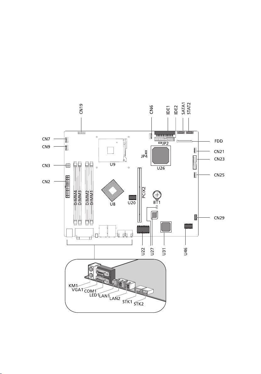
Mainboard layout
The mainboard becomes accessible once you open the system. The
figure below is provided to help you indentify and locate connectors,
slots and ports.
9
Page 20

10
Item Description
BT1 Battery
CN2 ATX power connector (20 pin)
CN3 ATX power connector (4 pin)
2 System tour
CN6
CN7
CN9
CN19 Front Panel connector
CN21 CD-ROM power connector
CN23 ARMC Feature connector
CN25 Add-on card HDD LED connector
CN29 LPC debug card interface connector
COM1 Serial port
DIMM1
DIMM2
DIMM3
DIMM4
FDD Floppy disc drive connector
JP1 Clear CMOS
JP2 Password
JP4 Boot Block
Fan connectors
DIMM slots
KM1 PS/2 Mouse/Keyboard ports
LAN1
LAN2
LED1 Rear panel ID indicator
PCIX2 PCI riser slot
Gigabit Ethernet ports
Page 21

Item Description
11
IDE1
IDE2
STK1
STK2
U8 Canterwood-ES chipset (North bridge)
U9 CPU slot (478 pin)
U20 System clock generator
U22 Super I/O
U26 Hance-Rapids chipset (South bridge)
U27 BIOS
U31 ATI Rage XL
U46 VGA SDRAM
VGA1 VGA monitor port
Primary IDE connector
Secondary IDE connector
USB 2.0 ports
Page 22

12
Jumper settings (JP1) clear CMOS
Pin Number Pin Settings
1-2 Normal (default)
2-3 Clear CMOS
Jumper settings (JP2) Password
Pin Number Pin Settings
1-2 Normal (default)
2-3 Clear password
Jumper settings (JP4) Boot Block
Pin Number Pin Settings
2 System tour
1-2 Disabled (default)
2-3 Enabled
Page 23
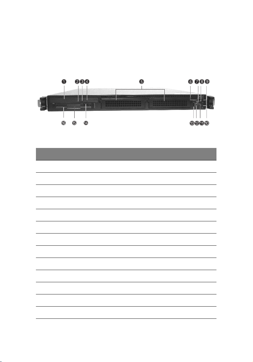
External and internal structure
Front panel
No. Description
1 CD-ROM drive
2 CD-ROM activity indicator
3 CD-ROM eject button
13
4 CD-ROM emergency eject hole
5 HDD bays
6ID indicator
7 HDD access indicator
8 System reset button
9 ID button
10 Power button
11 Fault indicator
12 System activity indicator
13 USB 2.0 port
Page 24
14
No. Description
14 FDD eject button
15 Floppy disc drive (FDD)
16 FDD activity indicator
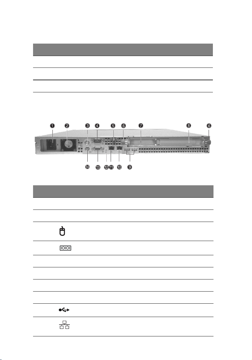
Rear panel
No. Icon Description
2 System tour
1 Main power supply unit
2 Main power supply fan-exhaust
3 PS/2 mouse port
4 Serial port
5 Top panel tool-less screw
6 System expansion card riser tool-less screws
7 Expansion card slot
8 Expansion card slot
9 USB 2.0 ports (two)
10
11
Gigabit LAN ports (10/100/1000 Mbps)
Page 25

No. Icon Description
12 ID ID indicator
13 SVGA/monitor port
14 PS/2 keyboard port
15
Page 26
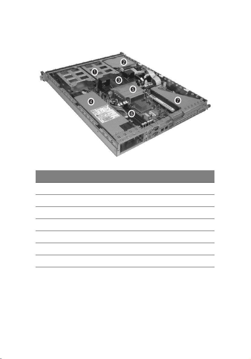
16
Internal components
No. Description
1 HDD bays
2 System tour
2 CD-ROM/FDD assembly
3 System fans
4 Power supply unit
5 CPU/heatsink/air-baffle assembly
6 DIMM slots
7 Expansion card riser
Page 27

3 Getting Started
Page 28

This chapter gives information on setting up
and starting to use your system
Page 29

Setting up the system
Preinstallation requirements
Selecting a site
Before unpacking and installing the system, select a suitable site for
the system for maximum efficiency. Consider the following factors
when choosing a site for the system:
• Near a grounded power outlet
• Clean and dust-free
• Stable surface free from vibration
• Well-ventilated and away from sources of heat
• Secluded from electromagnetic fields produced by electrical
devices such as air conditioners, radio and TV transmitters, etc.
Checking the package contents
Check the following items from the package:
• Acer Altos R310 system
• Acer Altos R310 User’s guide
• Acer Altos R310 Accessory box
19
If any of the above items are damaged or missing, contact your dealer
immediately.
Save the boxes and packing materials for future use.
Page 30

20
3 Getting Started
System startup
Turning on the system
After making sure that you have properly set up the system and
connected all the required cables, you can now power on the system.
To power on the system, press the power button on the front panel.
Refer to “Front panel” on page 13, for help locating the power button.
The system starts up and displays a welcome message. After that, a
series of power-on self-test (POST) messages appears. The POST
messages indicate if the system is running well or not.
Note: If the system does not turn on or boot after pressing the
power button, go to “Power-on problems” on page 21 for
possible causes of boot failure.
Aside from the POST messages, you can determine if the system is in
good condition by checking if the following occur during startup:
• Power indicator on the front panel lights up (green)
• Num Lock, Caps Lock, and Scroll Lock indicators on the keyboard
light up
Page 31

Turning off the system
To turn off the server, on the Windows task bar click on the Start
button, point to Shut Down..., select Shut down from the dropdown window then click on OK. You can then turn off all peripherals
connected to your server.
If you are unable to shutdown the server within Windows, press and
hold the power button for at least four seconds to force quit all
applications and shut down.
Power-on problems
If the system does not boot after you have applied power, check the
following factors that might have caused the boot failure.
• The external power cable may be loosely connected.
Check the power cable connection from the power source to the
power cable socket on the rear panel. Make sure that the cable is
properly connected to the power source and to the power cable
socket.
• No power comes from the grounded power outlet.
Have an electrician check your power outlet.
• Loose or improperly connected internal power cables.
Check the internal cable connections. If you are not confident to
perform this step, ask a qualified technician to assist you.
21
Warning! Make sure all power cords are disconnected from
the electrical outlet before performing this task.
Note: If you have gone through the preceding actions and the
system still fails to boot, ask your dealer or a qualified technician
for assistance.
Page 32

22
3 Getting Started
BIOS POST Checkpoint Codes
The POST code checkpoints are references and instructions used
during the BIOS pre-boot process. The following table describes
the checkpoints and associated beep codes, if any, that may
occur during the POST portion of the BIOS
.
Checkpoint
Code
01h One short
02h Verify Real Mode. If the CPU is in protected
03h Disabel Non-Maskable Interrupts (NMI).
04h Get CPU type from CPU registers and other
06h Initialize system hardware. Reset the DMA
07h Disable system ROM shadow and start to
Beep Code Description
beep before
boot
mode, turn on A20 and pulse the reset line,
forcing a shutdown 0.
NOTE: Hook routine should not alter DX,
which holds the powerup CPUID.
methods.
Save CPU type in NVRAM.
NOTE: Hook routine should not alter DX,
which holds the powerup CPUID.
controllers, disable video, clear any pending
interrupts from the real-time clock and
setup port B register.
execute ROMEXEC code from the flash part.
This task is pulled into the build only when
the ROMEXEC relocation is installed.
08h Initialize chipset registers to the Initial POST
Values.
Page 33

23
Checkpoint
Code
09h Set in-POST flag in CMOS that indicates we
0Ah Initialize CPU registers.
0Bh Enable CPU cache. Set bits in CMOS related
0Ch Set the initial POST values of the cache reg-
0Eh Set the initial POST values of registers in the
0Fh Enable the local bus IDE as primary or
Beep Code Description
are in POST. If this bit is not cleared by postClearBootFlagJ (AEh), the BIOS on next boot
determines that the current configuration
caused POST to fail and uses default values
for configuration.
Clear the CMOS diagnostic byte (register E).
Check the real-time clock and verify the battery has not lost power. Checksum the
CMOS and verify it has not been corrupted.
to cache.
isters if not integrated into the chipset.
integrated I/O chip.
secondary depending on other drives
detected.
10h Initialize power management.
11h General dispatcher for alternate register ini-
tialization.
Set initial POST values for other hardware
devices defined in the register tables.
12h Restore the contents of the CPU control
word whenever the CPU is reset.
13h Early reset of PCI devices required to disable
bus master. Assumes the presence of a stack
and running from decompressed shadow
memory.
Page 34

24
3 Getting Started
Checkpoint
Code
14h Verify that the 8742 keyboard controller is
16h 1-2-2-3 Verify that the ROM BIOS checksums to
17h Initialize external cache before autosizing
18h Initialize all three of the 8254 timers. Set the
1Ah Initialize DMA command register with these
Beep Code Description
responding. Send a self-test command to
the 8742 and wait for results. Also read the
switch inputs from the 8742 and write the
keyboard controller command byte.
zero.
memory.
clock timer (0) to binary count, mode 3
(square wave mode), and read/write LSB
then MSB. Initialize the clock timer to zero.
Set the RAM refresh timer (1) to binary
count, mode 2 (Rate Generator), and read/
write LSB only. Set the counter to 12H to
generate the refresh at the proper rate. Set
sound timer (2) to binary count, mode 3,
and read/write LSB, then MSB.
settings:
1. Memory to memory disabled
2. Channel 0 hold address disabled
3. Controller enabled
4. Normal timing
5. Fixed priority
6. Late write selection
7. DREQ sense active
8. DACK sense active low
Initialize all 8 DMA channels with these
settings:
1. Single mode
2. Address increment
3. Auto initialization disabled (channel 4 -
Cascade)
4. Verify transfer
Page 35

25
Checkpoint
Code
1Ch Initialize interrupt controllers for some shut-
20h 1-3-1-1 Verify that DRAM refresh is operating by
22h 1-3-1-3 Reset the keyboard.
24h Set segment-register addressibility to 4 GB.
28h 1-3-3-1 Using the table of configurations supplied
29h 1-3-3-2 Initialize the POST Memory Manager.
2Ah Zero the first 512K of RAM.
2Ch 1-3-4-1 Test 512K base address lines.
2Eh 1-3-4-3 Test first 512K of RAM.
Beep Code Description
downs.
polling the refresh bit in PORTB.
by the specific chipset module, test each
DRAM configuration to see if that particular
configuration is valid. Then program the
chipset to its autosized configuration.
Before autosizing, disable all caches and all
shadow RAM.
2Fh Initialize external cache before shadowing.
32h Compute CPU speed.
33h Initialize the Phoenix Dispatch Manager.
34h 1-4-2-1 CMOS test.
36h Vector to proper shutdown routine.
38h Shadow the system BIOS.
3Ah Autosize external cache and program cache
size for enabling later in POST.
Page 36

26
3 Getting Started
Checkpoint
Code
3Ch If CMOS is valid, load chipset registers with
3Dh Load alternate registers with CMOS values.
41h Initialize extended memory for RomPilot.
42h Initialize interrupt vectors 0 thru 77h to the
45h Initialize all motherboard devices.
46h 2-1-2-3 Verify the ROM copyright notice
47h Initialize support for I2O by initializing glo-
48h Verify that the equipment specified in the
Beep Code Description
values from CMOS, otherwise load defaults
and display Setup prompt. If Auto Configuration is enabled, always load the chipset
registers with the Setup defaults.
Register-table pointers are in the altregtable segment.
BIOS general interrupt handler.
bal variables used by the I2O code. Pause
POST table processing if a CMOS bit is set
(for debugging).
CMOS matches the hardware currently
installed. If the monitor type is set to 00
then a video ROM must exist. If the monitor
type is 1 or 2 set the video switch to CGA. If
monitor type 3, set the video switch to
mono. Also specify in the equipment byte
that disk drives are installed. Set appropriate status bits in CMOS or the BDA if configuration errors are found.
Page 37

27
Checkpoint
Code
49h Perform these tasks:
4Ah Initialize all video adapters in system.
4Bh Initialize QuietBoot if it is installed. Enable
4Ch Shadow video BIOS ROM if specified by
Beep Code Description
1. Size the PCI bus topology and set bridge
bus numbers
2. Set the system max bus number
3. Write a 0 to the command register of
every PCI device
4. Write a 0 to all 6 base registers in every
PCI device
5. Write a -1 to the status register of every
PCI device
6. Find all IOPs and initialize them.
both keyboard and timer interrupts (IRQ0
and IRQ1). If your POST tasks require interrupts off, preserve them with a PUSHF and
CLI at the beginning and a POPF at the end.
If you change the PIC, preserve the existing
bits.
Setup, and CMOS is valid and the previous
boot was OK.
4Eh Display copyright notice.
4Fh Initialize MultiBoot. Allocate memory for
50h Display CPU type and speed.
51h Checksum CMOS and initialize each EISA
52h Verify keyboard reset.
54h Initialize keystroke clicker if not enabled in
55h Enable USB devices.
old and new MultiBoot history tables.
slot with data from the initialization data
block.
Setup.
Page 38

28
3 Getting Started
Checkpoint
Code
58h 2-2-3-1 Test for unexpected interrupts. First do an
59h Register POST Display Services, fonts, and
5Ah Display prompt “Press F2 to enter SETUP.”
5Bh Disable CPU cache.
5Ch Test RAM between 512K and 640K.
60h Determine and test the amount of extended
62h Perform an address line test on A0 to the
Beep Code Description
STI for hot interrupts. Secondly, test the NMI
for an unexpected interrupt. Thirdly, enable
the parity checkers and read from memory,
checking for an unexpected interrupt.
languages with the POST Dispatch Manager.
memory available. Determine if memory
exists by writing to a few strategic locations
and see if the data can be read back. If so,
perform an address-line test and a RAM test
on the memory. Save the total extended
memory size in the CMOS at cmosExtended.
amount of memory available. This test is
dependent on the processor, since the test
will vary depending on the width of memory (16 or 32 bits). This test will also use A20
as the skew address to prevent corruption
of the system memory.
64h Jump to UserPatch1. See "The POST Compo-
66h Set cache registers to their CMOS values if
67h Quick initialization of all Application Proces-
nent."
CMOS is valid, unless auto configuration is
enabled, in which case load cache registers
from the Setup default table.
sors in a multi-processor system.
Page 39

29
Checkpoint
Code
68h Enable external cache and CPU cache if
69h Initialize the handler for SMM.
6Ah Display external cache size on the screen if it
6Bh If CMOS is bad, load Custom Defaults from
6Ch Display shadow message.
6Eh Display the starting offset of the non-dis-
70h Check flags in CMOS and in the BIOS data
Beep Code Description
present.
Configure non-cacheable regions if neces-
sary.
NOTE: Hook routine must preserve DX,
which carries the cache size to the DisplayCacheSizeJ routine.
is non-zero.
NOTE: Hook routine must preserve DX,
which carries the cache size from the cacheConfigureJ routine.
flash into CMOS. If successful, reboot.
posable segment of the BIOS.
area for errors detected during POST. Display error messages on the screen.
72h Check status bits to see if configuration
76h Check status bits for keyboard-related fail-
7Ch Initialize the hardware interrupt vectors
7Dh Initialize Intelligent System Monitoring.
problems were detected. If so, display error
messages on the screen.
ures. Display error messages on the screen.
from 08 to 0F and from 70h to 77h. Also set
the interrupt vectors from 60h to 66h to
zero.
Page 40

30
3 Getting Started
Checkpoint
Code
7Eh The Coprocessor initialization test. Use the
80h Disable onboard COM and LPT ports before
81h Run late device initialization routines.
82h Test and identify RS232 ports.
83h Configure Fisk Disk Controller.
84h Test and identify parallel ports.
85h Display any ESCD read errors and configure
86h Initialize onboard I/O and BDA according to
87h Initialize motherboard configurable devices.
88h Initialize interrupt controller.
Beep Code Description
floating point instructions to determine if a
coprocessor exists instead of the ET bit in
CR0.
testing for presence of external I/O devices.
all PnP ISA devices.
CMOS and presence of external devices.
89h Enable NMI.
8Ah Initialize Extended BIOS Data Area and ini-
8Bh Setup interrupt vector and present bit in
8Ch Initialize both of the floppy disks and dis-
8Fh Count the number of ATA drives in the sys-
tialize the mouse.
Equipment byte.
play an error message if failure was
detected. Check both drives to establish the
appropriate diskette types in the BIOS data
area.
tem and update the number in bdaFdiskcount.
Page 41

31
Checkpoint
Code
90h Initialize hard-disk controller. If the CMOS
91h Configure the local bus IDE timing register
92h Jump to UserPatch2.
93h Build MPTABLE for multi-processor boards.
95h 1. Check CMOS for CD-ROM drive present
96h Reset segment-register addressibility from
Beep Code Description
RAM is valid and intact, and fixed disks are
defined, call the fixed disk init routine to
intialize the fixed disk system and take over
the appropriate interrupt vectors.
based on the drives attached to it.
2. Activate the drive by checking for media
present
3. Check sector 11h (17) for Boot Record Volume Descriptor
4. Check the boot catalog for validity
5. Pick a boot entry
6. Create a Specification Packet
4GB to normal 64K by generating a Shutdown 8.
97h Create pointer to MP table in Extended
BDA.
98h 1-2 Search for option ROMs. ROM scan the area
99h Check support status for Self-Monitoring
9Ah Shadow miscellaneous ROMs if specified by
from C800h for a length of
BCP_ROM_Scan_Size (or to E000h by
default) on every 2K boundry, looking for
add on cards that need initialization.
Analysis Reporting Technology (disk-failure
warning).
Setup and CMOS is valid and the previous
boot was OK.
Page 42

32
3 Getting Started
Checkpoint
Code
9Ch Set up Power Management. Initiate power -
9Dh Initialize Security Engine.
9Eh Enable hardware interrupts.
9Fh Check the total number of Fast Disks (ATA
A0h Verify that the system clock is interrupting.
A2h Setup Numlock indicator. Display a message
A4h Initialize the typematic rate.
A8h Overwrite the "Press F2 for Setup" prompt
AAh Scan the key buffer to see if the F2 key was
ACh Enter SETUP
Beep Code Description
management state machine.
and SCSI) and update the bdaFdiskCount.
if key switch is locked.
with spaces, erasing it from the screen.
struck after keyboard interrupts were
enabled. If an F2 keystroke is found, set a
flag.
If (F2 was pressed)
go to SETUP
Else if (errors were found)
display "Press F1 or F2" prompt
if (F2 is pressed)
go to setup
else if (F1 is pressed)
boot
Else boot
AEh Clear ConfigFailedBit and InPostBit in
CMOS.
Page 43

33
Checkpoint
Code
B0h Check for errors
B1h Inform RomPilot about the end of POST.
B2h Change status bits in CMOS and/or the BIOS
B4h One quick beep.
B5h Turn off <Esc> and <F2> key checking.
Beep Code Description
If (errors were found)
beep twice
display "F1 or F2" message
if (F2 keystroke) go to SETUP
if (F1 keystroke) go to BOOT
data area to reflect the fact that POST is
complete.
IF (VGA adapter is present)
IF (OEM screen is still up)
Note OEM screen is gone.
Fade out OEM screen.
Reset video: clear screen, reset cursor, reload
DAC.
ENDIF
ENDIF
B6h If password on boot is enabled, a call is
made to Setup to check password. If the
user does not enter a valid password, Setup
does not return.
B7h Initialize ACPI BIOS.
B9h Clear all screen graphics before booting.
BAh Initialize the SMBios header and sub-struc-
BCh Clear parity-error latch.
BDh Display Boot First menu if MultiBoot is
tures.
intstalled.
Page 44

34
3 Getting Started
Checkpoint
Code
BEh If BCP option is enabled, clear the screen
BFh Check virus and backup reminders. Display
C0h Try to boot with INT 19.
C1h Initialize the Post Error Manager.
C2h Write PEM errors.
C3h Display PEM errors.
C4h Initialize system error handler.
C5h PnPnd dual CMOS (optional).
C6h Initialize note dock.
C7h Initialize note dock late.
C8h Force check (optional).
C9h Extended checksum (optional).
Beep Code Description
before booting.
System Summary.
CAh Redirect Int 15h to enable target board to
CBh Redirect Int 13h to Memory Technologies
CDh Redirect Int 10h to enable target board to
CEh Initialize digitizer device and display
D2h Unknown interrupt.
Dfh 4-2-4-4 A20 test error.
E0h Initialize the chipset.
use remote keyboard (PICO BIOS).
Devices such as ROM, RAM, PCMCIA, and
serial disk (PICO BIOS).
use a remote serial video (PICO BIOS).
installed message if successful.
Page 45

35
Checkpoint
Code
E1h Initialize the bridge.
E2h Initialize the CPU.
E3h Initialize system timer.
E4h Initialize system I/O.
E5h Check force recovery boot.
E6h Checksum BIOS ROM.
E7h Go to BIOS.
E8h Initialize Multi-Processor
E9h Set huge segment.
EAh Initialize OEM special code.
EBh Initialize PIC and DMA.
ECh Initialize Memory type.
EDh Initialize Memory size.
Beep Code Description
EEh Shadow Boot Block.
EFh System memory test.
F0h Initialize interrupt vectors.
F1h Initialize Run Time Clock.
F2h Initialize video.
F3h Initialilze System Management Mode.
F4h Output one beep.
F5h Boot to Mini DOS.
F6h Clear Huge Segment.
F7h Boot to Full DOS.
Page 46

36
3 Getting Started
Page 47

4 Configuring
the system
Page 48

This chapter discusses the precautionary
measures and installation procedures you
need to know when upgrading the system.
Page 49

Upgrading the system
Certain components of the server are upgradeable such as the drives,
the CPU, the memory, and the expansion cards. However, for safety
purposes, we do not recommend that you perform these upgrades
yourself. If you want to replace or upgrade any of these components,
contact your dealer or a qualified service technician for assistance.
Important: Observe the installation precautions described in the
subsequent section when installing or removing a server
component.
39
Page 50

40
4 Configuring the system
Installation precautions
Before you install any server component, we recommend that you read
the following sections. These sections contain important ESD
precautions along with preinstallation and post-installation
instructions.
ESD precautions
Electrostatic discharge (ESD) can damage the processor(s),
motherboard, disk drive(s), expansion board(s), or other components.
Always observe the following precautions before you install server
components:
1 Do not remove a component from its protective packaging until
you are ready to install it.
2 Wear a wrist grounding strap and attach it to a metal part of the
server before handling components. If a wrist strap is not
available, maintain contact with the server throughout any
procedure requiring ESD protection.
Page 51

Preinstallation instructions
Always observe the following before you install any component:
1 Turn off the system and all the peripherals connected to it.
2 Unplug all cables from the power outlets.
3 Open the system according to the instructions on page 42.
4 Follow the ESD precautions described in this section when
handling a server component.
5 Remove any expansion board(s) or peripheral(s) that block access
to the DIMM socket or other component connector.
See the following sections for specific installation instructions on the
component you want to install.
Warning! Failure to properly turn off the server before you
start installing components may cause serious damage. Do
not attempt the procedures described in the following
sections unless you are a qualified service technician.
Post-installation instructions
Observe the following after installing a server component:
1 See to it that all components are installed according to the
described step-by-step instructions.
2 Reinstall any expansion board(s) or peripheral(s) that you have
previously removed.
3 Reinstall the chassis panels.
4 Connect the necessary cables.
5 Turn on the system.
41
Page 52

42
4 Configuring the system
Opening the server
Caution! Before you proceed, make sure that you have turned off
your system and all peripherals connected to it. Read the
“Preinstallation instructions” on page 41.
You need to open the server before you can install additional
components. The top panel is removable to allow access to the system’s
internal components. Refer to the following sections for instructions.
Before opening the server
Before opening the server, observe the following precautions:
1 Turn off the system and all the peripherals connected to it.
2 Unplug all cables from the power outlets.
3 Place the system unit on a flat, stable surface.
Note: Because of the R310 design specification, the top panel
needs to be removed to access the system board.
Page 53

To remove the top panel
The top panel is attached to the server by one (non-removable)
thumbscrew. See “Rear panel” on page 14 for help locating the
screw.
To remove the top panel:
1 Loosen the thumbscrew located at the top-middle of the rear
panel (1).
2 Slide the panel rearward (2) and lift to detach it from the
chassis.
43
Page 54

44
4 Configuring the system
To replace the top panel
Align the cover over the chassis, with the tool-less screw oriented
toward the back panel of the server. Slide the cover toward the front
(1) and secure the cover by tightening the thumbscrew (2).
Observe the post-installation instructions described on page 41.
Page 55

Installing expansion cards
This section explains how to install an expansion card. The onboard
expansion slots support PCI (Peripheral Component Interconnect)
cards. Before installing expansion cards, observe ESD precautions and
Pre-installation precautions as noted on page 40.
Note: The BIOS setup automatically detects and assigns resources
to the new device (applicable only to Plug-and-Play expansion
cards).
To install an expansion card
1 Remove the system cover. See “To remove the top panel” on page
43 for more information.
2 Loosen the thumbscrews on the expansion card riser bracket (1),
then gently lift the riser from the chassis (2).
45
3 Remove the expansion slot cover from the rear of the metal
bracket.
Page 56

46
4 Configuring the system
4 Align and insert the PCI card onto the slot bracket (1), then
reinstall the PCI riser into the housing (2). Turn the thumbscrews
clockwise to secure the bracket (3).
5 Observe the post-installation instructions described on page 41.
Page 57

Installing and removing a hard disc drive
Removing a hard disc
1 Remove the system cover. See “To remove the top panel” on page
43 for more information.
2 Remove the front bezel from the system. Press the release buttons
at either end.
3 Disconnect all cables from the back of the hard discs (1) and (2).
Turn the thumbscrew counter-clockwise (3) to release the HDD
tray and gently slide it forward, out of the system (4).
47
Page 58
48
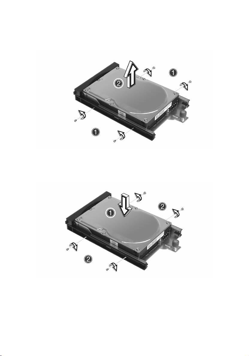
4 Remove the screws that secure the hard disc to the disc tray (1)
and remove the drive from the tray (2). Keep the screws for later
use.
4 Configuring the system
Installing a hard disc
1 Insert the new hard disc drive into the disc tray (1) and secure it
with the four screws you removed in the previous step (2).
Page 59

2 Reinsert the disc tray into the front of the system (1). Turn the
thumbscrew clockwise to secure the disc tray (2), and reconnect all
hard disc cables (3) and (4).
3 Replace the system cover and the front bezel, making sure to
observe the post-installation instructions described on page 41.
49
Page 60

50
4 Configuring the system
Upgrading the CPU
This section includes instructions for removing and installing a CPU.
Important! Always observe the ESD precautions when installing
or removing a system component. Refer to page 40.
Removing a CPU
1 Remove the system cover. See “To remove the top panel” on page
43.
2 Locate the CPU/heatsink/air-baffle assembly on the mainboard. See
“Mainboard layout” on page 9.
Warning! The heatsink may be very hot. After opening the
system, allow the heatsink to cool for several minutes if
the system was operating before you removed the cover.
3 Remove the air-baffle from the heatsink, as shown below.
Page 61

4 Loosen the four corner screws that secure the heatsink to the
mainboard (1) and gently remove it (2).
5 Locate and lift the CPU socket locking lever (3) to release the
processor. Gently pull up on the processor (4) to remove it.
51
Page 62

52
4 Configuring the system
Installing a CPU
Having followed the steps above, the CPU socket is empty and you are
ready to install your new processor.
1 Insert the CPU into the mainboard socket (1), making sure the
indicator on the processor is aligned with the indicator on the
socket. Lower the CPU locking lever to secure the processor (2).
Page 63

2 Replace the heatsink over the CPU socket (3) and tighten the four
corner screws (4).
3 Replace the system cover, making sure to observe the post-
installation instructions described on page 41.
53
Page 64

54
4 Configuring the system
Upgrading the system memory
Memory configuration
This section includes instructions for removing and installing a memory
module.
The following table illustrates the greater efficiency of 2-way memory
interleave configurations as compared to a 1-way memory interleave
configuration.
Warning! Functionality issues may be encountered if mixed
memory types are installed on the same server board. DIMM
modules of identical type, banking and stacking technology, and
vendor should be installed in the Altos R310.
Page 65

To re m o v e a DIMM
Before installing a new DIMM in a socket, remove first any previously
installed DIMM from that socket.
Important: Before removing any DIMM from the mainboard,
make sure to create a backup file of all important data.
1 Observe the ESD precautions and pre-installation procedures
described on page 41.
2 Locate the DIMM sockets on the mainboard.
3 Press the holding clips on both sides of the socket outward to
release the DIMM (1).
4 Gently pull the DIMM upward to remove it from the socket (2).
55
Note: Place your forefingers on the top of the DIMM before
pressing the holding clips to gently disengage the DIMM from the
socket.
Page 66

56
4 Configuring the system
To install a DIMM
1 Observe the ESD precautions and pre-installation procedures
described on page 40.
2 Locate the DIMM sockets on the mainboard.
3 Open the clips on the socket.
4 Align and insert the DIMM into the socket (1).
5 Press the holding clips inward to lock the DIMM in place (2).
DIMMs must be installed in the following order: DM1. DM2, DM3 and DM4
Note: The DIMM socket is slotted to ensure proper installation.
If you insert a DIMM but it does not fit easily into the socket, you
may have inserted it incorrectly. Reverse the orientation of the
DIMM and insert it again.
6 Observe the post-installation instructions described on page 41.
Reconfiguring the system memory
The system automatically detects the amount of memory installed.
Run the BIOS setup to view the new value for total system memory and
make a note of it.
Page 67

5 BIOS setup
Page 68

This chapter gives information about the
system BIOS and discusses how to configure
the system by changing the settings of the
BIOS parameters.
Page 69

59
BIOS setup
BIOS setup is a hardware configuration program built into your
system's Basic Input/Output System (BIOS). Since most systems are
already properly configured and optimized, there is no need to run this
utility. You will need to run this utility under the following conditions:
• When changing the system configuration
• When a configuration error is detected by the system and you are
prompted ("Run Setup" message) to make changes to the BIOS
setup
Note: If you repeatedly receive Run Setup messages, the battery
may be bad. In this case, the system cannot retain configuration
values in CMOS. Ask a qualified technician for assistance.
• When redefining the communication ports to prevent any conflicts
• When making changes to the Power Management configuration
• When changing the password or making other changes to the
security setup
BIOS setup loads the configuration values in a battery-backed
nonvolatile memory called CMOS RAM. This memory area is not part
of the system RAM which allows configuration data to be retained
when power is turned off.
Before you run BIOS setup, make sure that you have saved all open
files. The system reboots immediately after you close setup.
Page 70

60
5 BIOS setup
Entering BIOS setup
Power on the server to start the system POST (Power On Self Test)
process. During bootup, press F2 to enter the BIOS setup screen.
Note: You must press F2 while the system is booting. This key
stroke function does not work at any other time.
There are several tabs on the setup screen corresponding to the six
major BIOS menus:
•Main
•Advanced
•Power
• Boot
•Security
• Exit
The parameters on the screens shown in this User’s guide display
default system values. These values may not be the same as those in
your system.
Note the following reminders when moving around the setup screen:
•Use the Left and Right arrow keys to move to the next page or to
return to the previous screen.
• Use the Up and Down arrow keys to select an item.
• Use the + and - keys to select an option.
Note: You can configure a parameter that is enclosed in square
brackets. Grayed-out items have fixed settings and are not
user-configurable.
• Use the Tab key to select a field.
Page 71

61
• Use the Enter key to display a submenu screen.
Note: When a parameter is preceded by a (>), it means that a
submenu screen is available.
• Press F1 for General Help on using the BIOS setup.
• Press F10 to save changes and close the BIOS setup.
• Press Esc to close the BIOS setup without saving changes.
In the descriptive table following each of the screen illustrations,
settings in boldface are the default and suggested parameter settings.
Page 72

62
5 BIOS setup
Main
The Main menu displays basic and important information about the
system. This information is necessary for troubleshooting and may be
required when asking for technical support.
The last two parameters on the screen let you define the system’s time
and date settings. The real-time clock keeps the system date and time.
After setting the date and time, you do not need to enter them every
time you turn on the system. As long as the internal battery remains
good and connected, the clock continues to keep the date and time
accurately even when the power is off.
Parameter Description Option
BIOS Date The date when BIOS was built. [03/04/04]
BIOS Version The version of current BIOS. R01-A3A3
SMBIOS Version Supports DMTF SMBIOS version. 2.3.4
ASF Version Supports DMTF ASF version. 2.0
Page 73

Parameter Description Option
System Time Sets the correct time. [HH:MM:SS]
63
System Date Sets the correct date. [mm/dd/
Legacy Diskette A:
Primary IDE Master
Primary IDE Slave
Secondary IDE Master
Secondary IDE Slave
Third IDE Master
Fourth IDE Master
Display drive type if detected. N/A
yyyy]
Page 74

64
5 BIOS setup
Advanced
The Advanced menu contains parameter values that define how the
system behaves on startup.
Warning! Be cautious in setting parameter values in the
Advanced menu as any incorrect value may cause the
system to malfunction.
Press Enter to enter the submenu screen of the parameters shown in
the screen below.
Page 75

Parameter Description Option
65
PCI Configuration
Peripheral Configuration
Boot Settings Configuration
Event Log Configuration
Console Redirection
System Health Monitoring
ASF Configuration
Large Disk Access Mode DOS
Parallel ATA Both
Serial ATA Enabled
Native Mode Operation Auto
Serial ATA RAID Enabled
Open the submenu to configure these settings by
pressing ‘Enter’.
N/A
Enter is the
only
option.
Disabled
Primary
Secondary
Disabled
Disabled
Page 76
66
5 BIOS setup
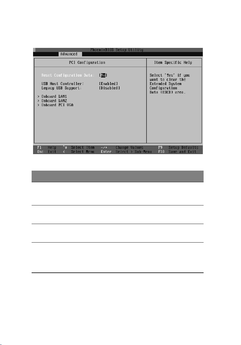
PCI Configuration
Parameter Description Option
Reset
Configuration
Data
USB Host
Controller
Legacy USB
Support
Onboard LAN1
Onboard LAN2
Onboard PCI VGA
No
Yes
Enables or disables the USB function in
Chipset.
Enables or disables support for legacy
USB devices.
Enables or disables onboard devices. N/A
Enabled
Disabled
Auto
Disabled
Enter is
the only
option
Page 77

Peripheral Configuration
The Peripheral Configuration submenu lets you define the parameter
settings for the system’s parallel and serial ports.
Parameter Description Options
67
Serial Port A
Serial Port B
Base I/O
address
Interrupt IRQ 4
Floppy Disk
Controller
Auto
Enabled
Disabled
3F8
2F8
3E8
2E8
IRQ 3
Enabled
Disabled
Page 78

68
Boot Settings Configuration
5 BIOS setup
Parameter Description Option
Quick Boot Allows BIOS to skip certain tests to
decrease the time needed while booting
the system.
Quiet Boot Displays the OEM logo when enabled; dis-
plays normal POST messages when disabled.
Summary
Screen
Hyper
Threading
Technology
Frequency
Ratio
Displays the CPU/Bus ratio of the system. X to 1
Enabled
Disabled
Enabled
Disabled
Enabled
Disabled
Enabled
Disabled
Page 79

Parameter Description Option
69
Bootup
NumLock
Wait for ‘F1’ if
Error
MPS Support 1.4
Memory Test Performs memory read/write test during
Floppy Check Displays the error message if floppy is not
Sets the Power-on state for NumLock. On
Off
Displays the error message if POST error
occurs.
POST.
detected.
Enabled
Disabled
Enabled
Disabled
Enabled
Disabled
Page 80

70
Event Log Configuration
5 BIOS setup
Parameter Description Option
Event Log
Capacity
Event Log Validity Displays event log status. Valid
Event Logging Allows logging of events and
Clear All Event
Logs
View Event Log Displays detail event log mes-
BIOS POST Even
Logging
Displays event log space status. Space Available
SMI/NMI.
Clears event log area and resets
to ‘No’ at next boot if Yes is
selected.
sages by pressing ‘Enter.’
Allows logging of BIOS POST
events.
Enabled
Disabled
Yes
No
N/A
Enter is the only
option.
Enabled
Disabled
Page 81

Parameter Description Option
71
ECC Event
Logging
PCI Event Logging Allows logging of PCI error
AC Power Lost/
Recovery
Reset Disabled
Memory Bank
Allows logging of ECC events. Enabled
events.
Enables all memory banks at the
next boot. Memory DIMM might
be disabled by memory reduction feature.
Disabled
Enabled
Disabled
Enabled
Disabled
Yes
No
Page 82

72
Console Redirection
5 BIOS setup
Parameter Description Option
Console Redirection Port
Baud Rate Sets the rate of communication. 9600 KB
Ter m inal Ty p e PC ANSI
Selects the system port for console redirection.
COM1
Serial Port A
Serial Port B
Disabled
19.2 KB
38.4 KB
57.6 KB
115.2 KB
VT100+
VT-UTF8
VT100
Page 83

Parameter Description Option
Flow Control No
CTS/RTS
XON/XOFF
CTS/RTS+CD
73
Continue C.R.
after POST
# of video
pages to support
On
Off
1 (Default)
through
8
Page 84

74
5 BIOS setup
System Health Monitoring
The system health monitoring screen displays current information
regarding the system’s CPU status, temperature status and fan status.
There are no user-configurable parameters on this page.
Page 85

Alert Standard Format (ASF) configruation
Parameter Description Option
75
BIOS Boot
Timeout
OS Boot
Timeout
Power-on wait
time
Sets the interval for the BIOS boot watchdog timer.
Sets the interval for the OS boot watchdog timer.
0
1-65535
0
1-65535
60
Page 86

76
Power
5 BIOS setup
Parameter Description Option
ACPI-aware OS Enable or disable ACPI support for
the Operating System.
Power Button
Behavior
AC Lost Handling
Sets the power state after shutdown due to power interrupt. If
set to ‘Off’ the system remains off.
If set to ‘Last State’ the system
returns to its last power state.
Yes
No
4-Sec. Override
Instant On/Off
Last State
Always On
Off
Page 87

Boot
Parameter Description
77
+Removable
Devices
CD-ROM Drive
+Hard Drive
PXE IBA GE Slot
0208 v1216
PXE IBA GE Slot
0430 v1216
Expandable
Allows user to configure Boot Sequence
Page 88

78
5 BIOS setup
Security
The Security menu allows you to safeguard and protect the system
from unauthorized use by setting up access passwords.
Parameter Description Options
Supervisor Password
User Password
Set Supervisor Password
Set User Password
Password On Boot Requires to input password
Displays ‘Installed’ if password is
set.
Sets password by pressing
‘Enter.’
before booting if this value is
enabled.
Clear
Installed
Enter
Enabled
Disabled
Page 89

79
Exit
The Exit menu displays the various options to quit from the BIOS setup.
Highlight any of the exit options then press Enter.
Parameter Description
Exit Saving
Changes
Exit Discarding
Changes
Load Setup
Defaults
Discard
Changes
Save Changes Saves all changes made to BIOS setup without exiting the
Saves changes made and closes the BIOS setup.
Discards changes made and closes the BIOS setup.
Loads the optimal settings for all BIOS setup parameters.
Optimal settings are quite demanding in terms of
resources consumption. If you are using low-speed memory chips or other kinds of low-performance components
and you choose to load these settings, the system might
not function properly.
Discards all changes made on the BIOS setup.
utility.
Page 90

80
5 BIOS setup
Page 91

Appendix A:
Management
software installation
Page 92

This appendix shows you how to install the
ASM and EasyBUILD
TM
software packages.
Page 93

Installing ASM
Acer Server Manager (ASM) consists of the ASM Console and the ASM
Agent. These two components are both required to perform server
management tasks.
System requirements
ASM requires TCP/IP connectivity between the ASM Console and the
ASM Agent.
ASM Agent
• Altos Server System
• Minimum of 128 MB RAM
• SCSI/IDE hard drive with at least 100 MB free hard disk space
• Windows 2000 server/advanced server, Windows server 2003 web/
standard/Enterprise editions, or RedHat Linux 7.3/8.0
ASM Console
• Intel Pentium III (500 MHz) or higher processor
• 128 MB of RAM
• SCSI/IDE hard drive with at least 100 MB free hard disk space
• Microsoft Windows 2000 Professional/XP/Server/Advanced Server
operating system
• Ethernet card
• Windows 2000 professional, Windows XP, Windows 2000 server/
advanced server, Windows server 2003 web/standard/Enterprise
editions
83
System setup
Make sure that your system meets the requirements listed above
before proceeding. You may also want to change your screen to
800 x 600 resolution or higher for optimum viewing.
Page 94

84
Appendix A: Management software installation
Installing ASM Agent (Windows version)
To install ASM Agent:
1 Log in to the managed server using the Administrator account.
TM
2 Insert the EasyBUILD
Management CD into the server’s CD-ROM
drive.
The installation sequence will automatically begin.
3 Select the option for ASM installation.
The installation wizard will be initialized.
4 Follow all onscreen instructions to complete installation.
For detailed instructions on installing ASM Agent, refer to the
ASM User’s manual.
ASM Agent will auto-launch as a Windows service after rebooting
the system.
Installing ASM Console (Windows version)
To install ASM Console:
1 Log in to the target Windows-based PC using the Administrator
account.
TM
2 Insert the EasyBUILD
CD-ROM drive.
The installation sequence will automatically begin.
3 Select the option for ASM installation.
The installation wizard will be initialized.
4 Follow all onscreen instructions to complete installation.
For detailed instructions on installing ASM Console, refer to the
ASM User’s manual.
Management CD into the computer’s
To launch the program, on the Windows taskbar click on the Start
button, point to programs, select Acer Server Manager then
click Acer Server Manager
Page 95

85
Installing ASM Agent (Linux version)
To install the ASM6 Agent on RedHat Linux 8.0
1 Insert the ASM6 installation CD into your computer's optical drive.
2 Mount the CD-ROM drive with "mount /dev/cdrom /mnt/cdrom"
command. For more information on mount command and the
options, please refer to RedHat Linux user's guide.
3 Change the working directory to ASM6 Linux Agent subdirectory
with the command "cd /mnt/cdrom/LinuxAgent".
4 Type in the command "./asmsetup install" to install the ASM6
Linux Agent. Follow the prompted installation guide, and you can
install the ASM6 Linux Agent with ease.
5 Umount the CD-ROM Drive with "umount /mnt/cdrom" command.
For detailed instructions on installing ASM Agent on Linux systems,
refer to the ASM User’s manual.
ASM agent will auto-launch demon service after rebooting the
system. There is no Linux version of ASM Console.
Page 96

86
Appendix A: Management software installation
Page 97

Appendix B: Rack
installation
Page 98

This appendix shows you how to use the
optional rack mount kit to put your Altos
R310 server into a server rack.
Page 99

89
System rack installation
Important! Observe the electrostatic discharge (ESD) precautions
shown on page 40 when perfoming the following procedures. Do
not attempt the procedures described in the following sections
unless you are a qualified technician.
Equipment rack precautions
Follow the rack manufacturer's safety and installation instructions for
proper rack installation.
The following additional rack safety installation measures should be
considered:
• Anchor the equipment rack
The equipment rack must be anchored to an unmovable suitable
support to prevent the rack from falling over when one or more
systems are fully extended out of the rack assembly. You must also
consider the weight of any other devices installed in the rack
assembly. The equipment rack must be installed according to the
manufacturer's instructions.
• Main AC power disconnect
You are responsible for installing an AC power disconnect for the
entire rack unit. This main disconnect must be readily accessible,
and it must be labeled as controlling power to the entire unit, not
just to the system(s).
• Earth ground the rack installation
To avoid the potential for an electrical shock hazard, the rack
assembly itself must be suitably earth grounded, according to your
local regional electrical codes. This typically will require the rack to
have its own separate earth ground. We recommend you consult a
locally certified electrician.
Page 100

90
Appendix B: Rack installation
• Elevated Operating Ambient Temperature
The maximum operating temperature of the system is 35
Careful consideration should be given to installing the system in
o
an environment compatible with the 35
C (95oF) maximum
ambient temperature.
• Reduced Airflow
The amount of airflow required for the safe operation of the
equipment should not be compromised when installing the system
in a rack.
• Mechanical Loading
Exercise care when mounting the system in a rack to avoid any
accidents.
• Circuit Overloading
Appropriate consideration should be given when connecting the
supply circuit to the system to avoid any circuit overload. The
system nameplate rating should be used when addressing
concerns about circuit overload.
o
C (95oF).
 Loading...