


Altos R300
User’s guide

Copyright © 2003 Acer Incorporated
All Rights Reserved.
Altos R300
User’s guide
Changes may be made periodically to the information in this publication without obligation
to notify any person of such revision or changes. Such changes will be incorporated in new
editions of this manual or supplementary documents and publications. This company makes
no representations or warranties, either expressed or implied, with respect to the contents
hereof and specifically disclaims the implied warranties of merchantability or fitness for a
particular purpose.
Record the model number, serial number, purchase date, and place of purchase information in
the space provided below. The serial number and model number are recorded on the label
affixed to your computer. All correspondense concerning your unit should include the serial
number, model number, and purchase information.
No part of this publication may be reproduced, stored in a retrieval system, or transmitted, in
any form or by any means, electronic, mechanical, photocopy, recording, or otherwise,
without the prior written permission of Acer Incorporated.
Model Number : _________________________________
Serial Number: ___________________________________
Purchase Date: ___________________________________
Place of Purchase: ________________________________
Acer and the Acer Logo are registered trademarks of Acer Inc. Other company’s product
names or trademarks are used herein for identification purposes only and belong to their
respective companies.

iii
Notices
FCC notice
This device has been tested and found to comply with the limits for a Class B
digital device pursuant to Part 15 of the FCC Rules. These limits are designed to
provide reasonable protection against harmful interference in a residential
installation. This device generates, uses, and can radiate radio frequency
energy, and if not installed and used in accordance with the instructions, may
cause harmful interference to radio communications.
However, there is no guarantee that interference will not occur in a particular
installation. If this device does cause harmful interference to radio or television
reception, which can be determined by turning the device off and on, the user
is encouraged to try to correct the interference by one or more of the following
measures:
• Reorient or relocate the receiving antenna
• Increase the separation between the device and receiver
• Connect the device into an outlet on a circuit different from that to which
the receiver is connected
• Consult the dealer or an experienced radio/television technician for help
Notice: Shield cables
All connections to other computing devices must be made using shielded cables
to maintain compliance with FCC regulations.
Notice: Peripheral devices
Only peripherals (input/output devices, terminals, printers, etc.) certified to
comply with the Class B limits may be attached to this equipment. Operation
with noncertified peripherals is likely to result in interference to radio and TV
reception.
Caution! Changes or modifications not expressly approved by the
manufacturer could void the user’s authority, which is granted by
the Federal Communications Commission, to operate this system.

iv
Use conditions
This part complies with Part 15 of the FCC Rules. Operation is subject to the
following two conditions: (1) this device may not cause harmful interference,
and (2) this device must accept any interference received, including interference
that may cause undesired operation.
Notice: Canadian users
This Class B digital apparatus meets all requirements of the Canadian
Interference-Causing Equipment Regulations.
Remarque à l’intention des utilisateurs canadiens
Cet appareil numérique de la classe B respected toutes les exigences du
Règlement sur le matériel brouilleur du Canada
.

Important safety information
Checking the power cords
Warning! To avoid electrical shock, do not attempt to
modify or use the supplied AC power cord(s), if they are
not the exact type required.
If a power cord(s) supplied is not compatible with the AC wall outlet in your
region, get one that meets the following criteria:
• The power cord must be properly rated for the AC voltage in your region.
• The power cord plug cap must have an electrical current rating that is at
least 125% of the electrical current rating of the product.
• The power cord plug cap that plugs into the wall socket-outlet must have a
grounding-type male plug designed for use in your region.
• The power cord must have safety certifications for your region, and shall
be marked with the certification markings.
• The power supply cord(s) is the main disconnect device to AC power. The
socket outlet(s) shall be near the equipment and shall be readily accessible
for disconnection.
Multiple power cords
v
Warning! To avoid electrical shock, disconnect all AC power cords before
accessing system internals.
Earth grounded socket outlets
Warning! To avoid electrical shock, the system power cord(s) must be plugged
into socket-outlet(s) that is/are provided with a suitable earth ground.

vi
Precautionary reminders
• Power supply modules
Power supply modules have double-pole/neutral fusing.
• Ventilation considerations
The equipment rack must provide sufficient airflow to the front of the
system to maintain proper cooling. The rack selected and the ventilation
provided must be suitable to the environment in which the system will be
used.
•Fans
To avoid injury do not touch moving fan blades.
• Cooling and airflow
For proper cooling and airflow, always install all access covers before
turning on the system. Operating the system for longer than five minutes
without the covers in place can cause overheating and damage to system
components.
• Temperature limits
The operating temperature of the system, when installed in the rack, must
not go below 10°C (50°F) or rise above 35°C (95°F). Extreme fluctuations in
temperature may cause a variety of system problems, and safety limits may
be broken.
• Lifting and Moving
Do not attempt to lift or move the system by the handles on the power
supplies.
• System covers
The system cover is an integral part of this product. If you need to open
your system to install new components, always remember to reinstall the
system cover before turning on the system.

vii
Important safety instructions
Read these instructions carefully. Save these instructions for future reference.
1 Follow all warnings and instructions marked on the product.
2 Unplug this product from the wall outlet before cleaning. Do not use
liquid cleaners or aerosol cleaners. Use a damp cloth for cleaning.
3 Do not use this product near water.
4 Do not place this product on an unstable cart, stand, or table. The product
may fall, causing serious damage to the product.
5 Slots and openings in the housing and the back or bottom are provided for
ventilation; to ensure reliable operation of the product and to protect it
from overheating, these openings must not be blocked or covered. The
openings should never be blocked by placing the product on a bed, sofa,
rug, or other similar surface. This product should never be placed near or
over a radiator or heat register, or in a built-in installation unless proper
ventilation is provided.
6 This product should be operated from the type of power indicated on the
marking label. If you are not sure of the type of power available, consult
your dealer or local power company.
7 Do not allow anything to rest on the power cord. Do not locate this
product where persons will walk on the cord.
8 If an extension cord is used with this product, make sure that the total
ampere rating of the equipment plugged into the extension cord does not
exceed the extension cord ampere rating. Also, make sure that the total
rating of all products plugged into the wall outlet does not exceed the fuse
rating.
9 Never push objects of any kind into this product through cabinet slots as
they may touch dangerous voltage points or short out parts that could
result in a fire or electric shock. Never spill liquid of any kind on the
product.
10 Do not attempt to service this product yourself, as opening or removing
covers may expose you to dangerous voltage points or other risks. Refer all
servicing to qualified service personnel.
11 Unplug this product from the wall outlet and refer servicing to qualified
service personnel under the following conditions:
a When the power cord or plug is damaged or frayed
b If liquid has been spilled into the product
c If the product has been exposed to rain or water

viii
d If the product does not operate normally when the operating
instructions are followed. Adjust only those controls that are covered
by the operating instructions since improper adjustment of other
controls may result in damage and will often require extensive work
by a qualified service personnel to restore the product to normal
condition.
e If the product has been dropped or the cabinet has been damaged
f If the product exhibits a distinct change in performance, indicating a
need for service.
12 Replace the battery with the same type as the product's battery we
recommend. Use of another battery may present a risk of fire or explosion.
Refer battery replacement to a qualified service personnel.
13 Warning! Batteries may explode if not handled properly. Do not
disassemble or dispose of them in fire. Keep them away from children and
dispose of used batteries promptly.
14 Use only the proper type of power supply cord set (provided in your
accessories box) for this unit.

Important installation instructions
Since Altos R300 is also considered to be rack-mountable, instructions
addressing suitable installation of the equipment in a rack are required to be
supplied by the equipment manufacturer. Through the use of simple statements
in the installation instructions, the following general hazards shall be
addressed. These potential hazards are considered common to most rack
installations:
1 Elevated operating ambient temperature
The details should be provided so that consideration shall be given to
installing the equipment in an environment compatible with the
manufacturer’s maximum rated ambient temperature 35°C (95°F).
2 Reduced air flow
Installation of the equipment in a rack shall be such that the amount of
airflow required for safe operation of the equipment is not compromised.
3 Mechanical loading
Mounting of the equipment in the rack shall be such that a hazardous
condition is not achieved due to uneven mechanical loading.
4 Circuit overloading
Consideration should be given to connection of the equipment to the
supply circuit and the effect that overloading circuits may have on
overcurrent protection and supply wiring. Appropriate consideration of
the equipment nameplate rating should be used when addressing this
concern.
5 Reliable earthing
Reliable earthing of the rack mounted equipment should be maintained.
ix

x
Laser compliance statement
The CD-ROM drive in this system is a laser product. The CD-ROM drive’s
classification label (shown below) is located on the drive.
CLASS 1 LASER PRODUCT
CAUTION: INVISIBLE LASER RADIATION WHEN OPEN. AVOID EXPOSURE TO
BEAM.

Notices iii
FCC notice iii
Important safety information v
Important safety instructions vii
Important installation instructions ix
Laser compliance statement x
1 System overview 1
Overview 3
Processors 3
Memory 4
System chipsets 4
Expansion slot 5
Hardware management support 5
Features summary 6
Weight 7
Power consumption 7
Thermal dissipation 8
2 System tour 9
External and internal structure 11
Front panel 11
Rear panel 12
Internal components 13
System board 14
Mainboard layout 14
Disk drives 17
Floppy disk drive 17
CD-ROM drive 18
Hard disk drive 19
Preinstallation requirements 20
Selecting a site 20
Checking the package contents 20
Basic connections 21
Connecting the PS/2 keyboard 21
Connecting the PS/2 mouse 22
Connecting the VGA monitor 23
Connecting the power cable 24
Connecting option 25
USB devices 25
Network 26
Turning on your system 27
Contents

Power-on problems 27
Turning off your system 29
3 Upgrading your system 31
Installation precautions 33
ESD precautions 33
Preinstallation instructions 33
Post-installation instructions 34
Opening your system 35
Removing the system cover 35
Replacing the system cover 36
Installing an expansion card 37
To install a PCI card on PCI slot 1 37
To install a PCI-SCSI card on PCI slot 2 39
Removing or installing the hard disk drive 41
Installing SCSI hard disks 45
Removing and installing the CPU 47
Removing the CPU 47
Installing the CPU 48
Removing and installing memory modules 50
Removing a DDR DIMM 50
Installing a DDR DIMM 51
4 BIOS Setup utility 53
BIOS Setup utility 55
Entering Setup 56
System Summary 58
Product Information 60
Devices and I/O Ports 61
Console Redirection 63
Serial Port Setup 66
USB Setup 67
IDE Primary Master Device 68
IDE Secondary Master Device 71
Start Options 73
Startup Sequence 75
Date and Time 76
System Security 77
Setting and changing the password 79
Removing a password 80
Advanced Setup 81
Memory/Cache Options 82
PnP/PCI Options 83

CPU Frequency 86
Memory Settings 88
Power Management 89
Error Log 90
View Event Log 91
Save Settings 92
Restore Settings 93
Load Default Settings 94
Exit Setup 95
Appendix A: ASM quick installation guide 97
Installing ASM 99
System requirements 99
System setup 100
Appendix B: Altos R300
Rack installation guide 103
System rack installation 105
Vertical mounting hole pattern 107
Screw types used 108
Installing cage nuts 109
Installing the system into the rack 110
To install the system into a four-post rack 110
To install the system into a two-post rack 115


1 System overview

The Altos R300 is a 1U, high-density,
rack-mountable single-processor system loaded
with a host of new and innovative features.
The system offers a new standard for flexible
productivity ideal for local or wide area
networks and multi-user server environments.

Overview
The Altos R300 system is a PCI bus based processor system built on an
optimized baseboard. It comes with a single socket 478 processor slot
utilizing an Intel
with the Server Works GC-SL core logic chipset consisting of three
distinct components: CMIC-SL, CIOBX2 and CSB5. The mainboard also
integrates two Broadcom BCM 5703 10/100/1000 Base-T Gigabit
Ethernet controllers solution for high performance network
applications reducing power consumption.
For expandability, the system includes two 64-bit/100 MHz PCI-X bus
slots and four DIMM slots that allow memory installation up to a
maximum capacity of 4 GB.
For connectivity, the mainboard provides two USB (Universal Serial Bus)
connectors, PS/2 interfaces for both mouse and keyboard, one UART
serial port, one monitor port and two LAN ports.
For media storage, Altos R300 supports one slim-type CD-ROM drive,
one slim-type floppy disk drive and a hard disk drive.
The system is fully compatible with Windows 2000 Server, SCO
OpenServer 5.0.6, Unixware 7.1.1, NetWare 6, and Red Hat Linux 8.
®
Pentium® 4 processor or Intel® Celeron processor
3
Processors
The Intel® Pentium® 4 processor implements a new scalable system bus
protocol. The system bus uses SST (Source-Synchronous Transfer) of
addresses and data to improve performance for servers or
workstations. With its on-die 512-KB level two (L2) cache implementing
the Advanced Transfer Cache Architecture, the Intel
processor delivers higher performance than previous Pentium III
processors while maintaining binary compatibility with all previous
®
Architecture processors.
Intel
The mainboard supports FSB (front-side bus) speed up to 533 MHz.
®
Pentium® 4

1 System overview4
Memory
The four DIMM sockets on board accept 256-, 512-MB or 1-GB DDR
(Double Data Rate) SDRAM for a maximum memory capacity of up to
4 GB.
For data integrity, the default setting for the ECC (error correcting
code) function of the memory system in BIOS is enabled.
Note: The mainboard supports PC2100/DDR-266 SDRAM DIMMs.
Refer to “Mainboard layout” on page 14 for the location of these
DIMM slots on the mainboard.
System chipsets
Server Works chipset
The Server Works GC-SL(Grand Champion – Super Lite) chipset is
specifically designed to meet the needs of high performance systems. It
consists of the following components:
• CMIC-SL (north bridge) is responsible for communication between
the processor, the memory bus, and the IMB (inter-module bus)
bus. It runs directly to the processor bus at 133MHz and integrates
the functions of main memory controller for DDR. IMB interface
unit runs at 400MHz and connects to CIOBX2, and one narrowversion of IMB (Thin-IMB) connects to South Bridge CSB5.
• CIOBX2 (I/O bridge) is a peripheral chip that performs PCI bridging
function between the IMB and the 2 PCI-X buses.
• CSB5 (south bridge) integrates the LPC interface that links super
I/O functions like keyboard and mouse interface, floppy disk
controller, advanced digital data separator, serial port, on-chip 12
mA AT bus drivers, one floppy direct drive support, and IPM
(intelligent power management) support.

LAN subsystem
Integrated in your system are two Gigabit Ethernet controllers,
BCM5703 10/100/1000BASE-T Ethernet LAN controllers. With
sophisticated 64-bit PCI component and combination of triple-speed
Ethernet transceiver, the LAN subsystem enables high-level command
processing and multiple solutions for high-performance network
applications.
Video subsystem
The ATI Rage XL harbors 2D and 3D display capabilities that bring life
to multimedia and work applications. It also supports hardware DVD
decoding. With remarkable color depth and high resolution of up to
1280 x 1024 it enhances every visual experience on your system.
The onboard ATI Rage XL chipset comes with 8 MB SDRAM and
supports up to 1280 x 1024 display mode at true color.
Expansion slot
PCI bus
5
The mainboard has two 64-bit/100 MHz PCI-X bus slots one onboard
and another on riser card.
Hardware management support
The mainboard supports a power management function that conforms
to the power saving standards of the U.S. Environmental Protection
Agency (EPA) Energy Star program. It also offers Plug-and-Play
features which help save users from configuration problems, making
the system more user-friendly.
Additional features include hardware support for ASM (Acer Server
Manager). ASM performs server management tasks. It detects
problems in the CPU thermal condition, CPU working voltage detection
(±12V/±5V/3.3V/1.5V), and PCI bus utilization calculation. It also
detects if the CPU fan or the chassis fan malfunctions.

1 System overview6
Features summary
The system has the following major components:
• FC-PGA (Flip-Chip Pin Grid Array) 478 processor socket that
supports :
•Intel
•Intel
• Server Works GC-SL chipset which includes the north, south and I/O
bridge
• Onboard dual Broadcom BCM 5703 10/100/1000 Base-T Gigabit
Ethernet controllers
• Four DIMM sockets that accept 256-, 512-MB and 1-GB DDR 266
SDRAM DIMMs for a maximum memory capacity of 4 GB
• Storage support for:
• One slim-type CD-ROM drive
• One slim-type floppy disk drive
• Two 64-bit/100 MHz PCI-X slots
• NS PC87414-ICK Super I/O chipset
• ATI Rage XL video chipset
• System clock/calendar with battery backup
• Auxiliary power connector for ATX power supply
• Advanced Server Management (ASM) controller chipsets
• External ports:
• 2 USB ports (front) • Serial port
• PS/2-compatible keyboard port • 2 LAN ports (RJ-45)
• PS/2-compatible mouse port • Monitor/VGA port
®
Pentium® 4 processor up to 3.06 GHz
(533 MHz system bus)
®
Celeron processor up to 2.2 GHz
(400 MHz system bus) or above

Weight
The table below lists the weight of individual components used in the
deployment of this system in third-party racks.
Item Weight in kg Weight in lbs
7
Fully configured system
(with rack mount kit)
Rack mount kit 3.1 kg 6.82 lbs
CPU and heat sink 0.6 kg 1.32 lbs
Hard disk drive 1kg 2.2 lbs
Power supply module 1.3 kg 2.86 lbs
Floppy disk drive 0.16 kg 0.35 lbs
CD-ROM drive 0.3 kg 0.66 lbs
PCI card 0.04 ~ 0.4 kg 0.09 ~ 0.88 lbs
13 kg 28.6 lbs
Power consumption
The server power supply is rated for a maximum 200W DC output.
Maximum input AC power consumption is approximately 307W.
• Using 110V AC power, a fully loaded system can consume up to
2.944A
• Using 200V AC power, a fully loaded system can consume up to
1.619A
Deployment of ultra-dense 1U servers represent a significant power
requirement. A simple formula to calculate server power requirements
for an installation is:
(Number of servers) x (307W) = maximum power requirements for servers

1 System overview8
Thermal dissipation
Altos R300 has the following cooling systems:
• Three 4-cm CPU fans
• One rear chassis fan
A fully configured Altos R300 server under maximum workload can
produce approximately 900 BTU/hr. Air temperature measurements
around the system may vary as much as 25°C (45°F) from front to back.
Deployment of multiple ultra-dense servers will produce a significant
amount of heat. For example, 42 server under maximum workload can
generate as much as 37,820 BTU/hr.

2 System tour

This chapter discusses the features and
components of your system. Instructions on
how to set up your system and connect basic
and optional peripherals are also explained.

External and internal structure
Front panel
No. Icon Description
1CD-ROM drive
2 CD-ROM drive indicator
3 CD-ROM drive eject button
4 CD-ROM drive emergency eject hole
5 Floppy disk drive indicator
11
6 Floppy disk drive
7 Floppy disk drive eject button
8 System event indicator
9 Hard disk activity indicator
10 Reset button
11 Power button
12 Power indicator
13 USB ports (2 ports)
14 Rack mount bracket thumbscrew

2 System tour12
Rear panel
No. Icon Color Description
1 Power cable socket
2 Add-on low profile PCI card bracket
thumbscrew
3 Fan blower
4 Add-on low profile PCI card bracket
5 Add-on PCI card bracket
6 Add-on PCI card bracket thumbscrew
7 Rear system fan
8 Teal or
turquiose
9 Black Gigabit LAN 1 port
10 Black Gigabit LAN 2 port
11 Blue Monitor/VGA port
12 Green PS/2 mouse port
13 Purple PS/2 keyboard port
Serial port
No. Icon Color Description
14 Power supply indicator
15 System event indicator
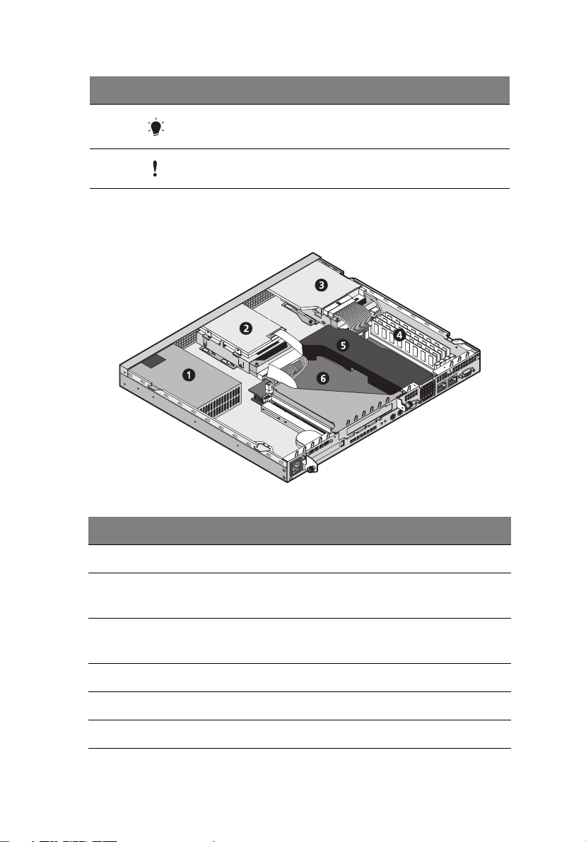
Internal components
13
No. Item
1 Power supply
2 Slim type floppy disk drive (top)
Hard disk drive (bottom)
3 Slim type CD-ROM drive (top)
Hard disk drive (bottom)
4 DIMM sockets
5 Air baffle
6 Mainboard

2 System tour14
System board
Mainboard layout
The mainboard becomes accessible once you open the system. It
should look like the figure shown below.
Item Description
BT1 Battery
CN1 LED board connector
CN2 Secondary IDE connector
CN3 Primary IDE connector
CN4 PSU (power supply unit) 12V input connector

Item Description
CN5 24-pin ATX power supply connector
CN6 USB connector
CN7 Slim-type FDD connector
CN12 ARMC (Altos Remote Management Card) connector
CN13 Wake on LAN connector
CN16 Lattice chip (not functioning)
CN17 Gigabit LAN port(RJ-45)
CN18 Gigabit LAN port (RJ-45)
CN19 Serial port
CN20 Monitor/VGA port
CN21 SCSI LED connector
CPU CPU socket
15
DIMM1 to
DIMM4
HFAN1 CPU cooling fan 1 connector
HFAN2 CPU cooling fan 2 connector
HFAN4 3-pin fan connector
JK1 PS/2 keyboard port
JK2 PS/2 mouse port
JP2 CMOS clear jumper
JP3 ASR (automatic server restart) disable jumper
JP4 Boot block jumper
JP5 HDD power connector
DIMM slots

Item Description
JP6 IMB training jumper
JP7 I2C bus connector
2 System tour16
LAN1 and
LAN2
LED5 Event LED
LED6 Power LED
P1 PCI slot (for debug card purpose only)
PCI slot 1 and
PCI slot 2
SW1 NMI (non-maskable interrupt) switch
SYSTEM FAN3 3-pin fan connector
U25 CMIC-SL (north bridge)
U26 CSB5 (south bridge)
U27 CIOBX2 (I/O bridge)
U35 ATI Rage XL VGA chipset
U44 BIOS Flash ROM
Broadcom BCM5703 Gigabit chips
64-bit/100 MHz PCI-X slots (3.3v)
 Loading...