

Page 1

Acer PH-112
Service Guide
Service guide files a nd updates are availa ble
on the CSD web; for more information,
plea se refer to http://csd.acer .com.tw
100% Recycled Pa per
Page 2

Copyright
Copyright © 2003 by Acer Incorporated. All rights reserved. No part of this publication
may be reproduced, tra nsmitted, tra nscribed, stored in a retrieval syste m, or tra nslated
into any la nguage or computer la nguage, in a ny f orm or by a ny mea ns, ele ctronic,
mechanical, magnetic, optical, che mical, ma nual or otherwise, without the prior written
permission of Acer Incorporated.
Disclaimer
The information in this guide is subject to change without notice.
Acer Incorporated makes no representations or warra nties, e ither expressed or
implied, with respect to the contents here of a nd spe cifically disclai ms a ny warranties
of merchanta bility or fitness f or a ny particular purpose. Any Acer Incorporated software
described in this manual is sold or licensed “as is”. Should the programs prove defec
tive following their purchase, the buyer (a nd not Acer Incorporated, its distributor , or its
dealer) a ssumes the entire cost of all ne cessary servicing, re pair , a nd any incidental or
consequential damages resulting from a ny defect in the software.
Acer is a registered trademark of Acer Corporation.
Intel is a registered trademark of Intel Corporation.
Pentium and Pentium II/III are trade marks of Intel Corporation.
Other brand a nd product n ames are trademark s a nd/or registered trad emarks of the ir respective holders.
Page 3
Conventions
The following conventions are used in this ma nual
segassemneercS.neercsnoraeppatahtsegassemlautcasetoneD
etoN
noitamrofnilanoitiddafoseceipdnastibseviG
.cipottnerrucehtotdetaler
gninraW
morftluserthgimtahtegamadynaotuoystrelA
.snoitcacificepsgniodtonrogniod
noituaC
elbissopdiovaotserusaemyranoituacerpseviG
.smelborperawtfosroerawdrah
tnatropmI
ehtottnavelersnoitcacificepsodotuoysdnimeR
.serudecorpfotnemhsilpmocca
Page 4

Preface
Before using this information and the product it supports, plea se rea d the f ollowing
general information.
1. This Service Guide provide s you with all technical inf ormation relating to the BASIC
CONFIGURA TION decided for Acer’s “global” product offering. To better fit local
market requirements and enhance product competitiveness, your regional office MAY
have decided to extend the functionality of a ma chine (e.g. add-on card, mode m, or
extra memory ca pa bility). These LOCALIZED FEA TURES will NOT be covered
in this generic service guide. In such ca ses, ple ase contact your region al off ices or the
responsible personnel/cha nnel to provide you with further technical details.
2. Plea se note WHEN OR DERING FRU PARTS, that you should check the most up-
to-date information available on your region al web or channel. If, f or whatever reason,
a part number cha nge is ma de, it will not be noted in the printed Service Guide. For
ACER-AUTHORIZED SERVICE PROVIDERS, your Acer office may have a DIFFER
ENT part number code to those given in the FRU list of this printed Service Guide.
You MUST use the list provided by your regional Acer of fice to order FRU parts f or
repair and service of customer machines.
Page 5

Chapter 1 Syste m Introduction 1
T echnical Spe cification .......................................................................................................1
La mp Specification............................................................................................................. 2
System Block Diagra m .......................................................................................................6
Optics Conceptual Drawing................................................................................................7
Cha pter 2 Firmware Update 8
Setup T ool / Equi pment.......................................................................................................8
Upgrading Procedure .........................................................................................................8
Chapter 3 M achine Dissa ssembly and Re pla cement 10
General Information ...........................................................................................................11
Disassemble Lamp Module...............................................................................................12
Disassemble IO Cover & Top Cover..................................................................................13
Disassemble Speaker & Front Cover ...............................................................................14
Disassemble Front Fan...................................... ...............................................................15
Disassemble Front IR Board & IR Cover...........................................................................16
Disassemble Video IO .......................................................................................................17
Dissassemble Main Board..... ...........................................................................................18
Disassemble Ballast Module & Back IR.............................................................................19
Disassemble Optical Engine..............................................................................................20
Disassemble Back Cover.................................................................................................. 21
Disassemble Back IR Cover , AC Outlet........................................................................... 22
Disassemble Power Module............................................................................................. 23
Disassemble Mylar & Ground Plate.................................................................................. 24
Disassemble Heatsink & DMD Board.............................................................................. 25
Disassemble DMD Assembly & DMD.............................................................................. 26
Disassemble Thermal Board............................................................................................ 27
Disassemble Optical Engine Fan...................................................................................... 28
Exploded Overview............................................................................................................29
Table of Contents
Page 6

Table of Contents
Chapter 4 Trouble shooting 30
Video Signal troubleshooting.............................................................................................31
Operation FunctionTroubleshooting............................................................................... ...34
Power SourceTroubleshooting..........................................................................................35
Function T e st and Align ment...............................................................................................36
Equipment Needed...................................................................................................36
T est Condition......................................................................................... ...................36
T est Display Modes a nd Patterns .....................................................................................37
Compatible Modes ..................................................................................................37
Function Test Display Pattern......................................................................... .........38
Chapter 5 Conne ctor Information 40
Introduction...........................................................................................................................40
Main Board......................................................................................................................... 40
Power Board .....................................................................................................................46
Ballast Board ......................................................................................................................48
Chapter 6 FRU(FieldReplaceable Unit) List 49
FRU List...............................................................................................................................50
Page 7

1 Chapter 1
System Introduction
Chapter
1
Technical Specification
Item Description
Display Type Single Chip DLP Projector
Lamp Type 200 W User Replaceable Lamp
Brightness 1600 Lumen
Contrast Ratio 2000 : 1(Full on / off) (Min)
Resolution(Pixels) 854 x 480
Uniformity 90%
Optical Compensation Light Tunnel
Focal Length 20.2 ~ 24.2 mm
Screen Size 27~324 inches Diagonal
Throw Distance 1.2 ~ 12 Meter
Compatibility
"Horizontal frequency (31~79KHz" )
"Vertical frequency ( 50~85Hz" )
Operation Humidity 80%
Operation Temperature +5 ~ +35C
Sound Noise 30dB(A)(standard mode)/28db(A) (ECO mode)
Power Requirement 100~240v, 50~60Hz
Dimensions ( W x H x D ) 256 x 198 x 92 mm
Weight 2.3 KG (<4.5 lb)
Certification
CE Class B, FCC Class B , VCCI-II , UL , cUL, TUV-GS, C-
tick, PSB, PSE, CB Report, CCC
Page 8
Chapter 1 2
Lamp Specification
1.Product Scope
The product is a lamp system consisting of a short arc burner in a reflector, and a lamp
driver.
Lamp type UHP 200W-150W 1.0
Driver type EUC 200V/01 TopValue
2. SYSTEM SPECIFICATIONS
2.1 Driver conditions
See driver specifications for more information
EUC 200V/01
* If the lamp voltage is below 35V continued over 90s, the driver shuts down.
** If the lamp voltage reaches over 140V, the driver shuts down immediately.
2.2 Run-up time
Run-up time to 80% of the stabilised luminous output is < 60s.
2.3 Ignition
2.3.1 Cold ignition
The criterion for reliable ignition is defined as a maximum of three ignition
failures on 30 attempts per amp however none of these ignition failures
may occur subsequently.
During the ignition phase of the lamp (run-up-time), no cooling of the burner
recommended. Cooling of the burner can lead to ignition failure.
Page 9

3 Chapter 1
It is known that asymmetric cooling after switching the lamp off, can lead to
ignition failure in the next attempt due to condensed mercury on 1 of the electrodes.
Therefore Philips advises to build in multiple attempts (max. 5 for safety reasons) to
start the lamp. Between 2 attempts one has to wait 15s.
Philips suggests after a successful starting attempt to keep the lamp burning for
at least 15 minutes.
The cable has an isolation value of 2.5kV
To limit voltage loss of the ignition pulse, the mutual capacity of the cables may
not exceed 40pF.
To ensure this, Philips recommends to:
Avoid twisted cables
Never tie the cables together
Avoid contact to conductive plates, especially if those are connected to ground
(e.g. via PE)
If possible keep the cables straightened having a mutual distance (of 1 to 2 cm
between the
A suitable electrical enclosure should be provided in the end-product. Creepage
and clearance distances to high voltage parts and traces have to be evaluated in
the end-product. Special consideration has to be given to the distances from earthed
mounting screws to hazardous voltage traces on the lamp driver PCB.
2.3.2 Hot restrike
At max. bulb temperature of 300 oC+ -25oC : 98% ignition reliability of the total
number of switches.
At max. bulb temperature of 300 oC+ -25oC : 99.9% ignition reliability of the total
number of switches.
A restrike of the system can be applied 15 seconds after shut down.
Restrikes of the system can be repeated up to max. 5 times, if the lamp has not
successfully started from the first time.
Philips suggests after a successful starting attempt to keep the lamp burning for at
least 15 minutes.
Page 10
Chapter 1 4
3 LAMP SPECIFICATIONS
3.1 Dimensions
Reflector type E19
3 Average lamp life and lumen maintenance
(on test & operational conditions see 4.4 and based upon a large sample
population)
When driven at 200W on ballast type EUC 200V/01 and temperature conditions
are fulfilled
(AN 2002-002)
> 85% 500h
> 50% 2000h According to the light specification table (see paragraph 4.5.2)
When driven at 150W on ballast type EUC 200V/01 and temperature conditions
are fulfilled
(AN 2002-002)
> 85% 500h
> 50% 2500h According to the light specification table (see paragraph 4.5.2)
Page 11

5 Chapter 1
4 INSTRUCTION FOR USE
- To replace the lamp, the power should be switched off.
- The burning position is horizontal ± 20°.
- Never touch the burner or reflector mirror with bare hands. If bare hands have touched
it, it should be cleaned with a lint free towel before installing the lamp.
- The lamp should be operated on the lamp driver as mentioned in paragraph 1.
- Fast switching cycles will reduce lamp life (e.g. 10min on 10min off).
- Max torque on the side and centre connector: 0.8Nm.
- The screw, which connects the cable with the side connector, may not touch the
reflector surface.
- The set maker must design a lamp house to keep glass pieces in the lamp house.
- Visible arc instability has to be suppressed by set optics.
5 ENVIRONMENTAL LAWS
EU
At end of service life, UHP Lamps should be treated as chemical waste (in view of
mercury content), and be
disposed of in compliance with national regulations/law.
USA
To comply in accordance with the Law of Vermont, that obliges the visible notification
on a lamp in case it
contains mercury, a Hg logo will be added on the reflector of the lamp. Besides the
reflector, also lamp
packaging with destination USA needs to notify the customer that the packaging
contains mercury added
products.
For more information about Hg marking, check the website of the Law of Vermont.
http://www.anr.state.vt.us/dec/ead/mercury/labeling/manufact.htm
Page 12
Chapter 1 6
System Block Diagram
Page 13
7 Chapter 1
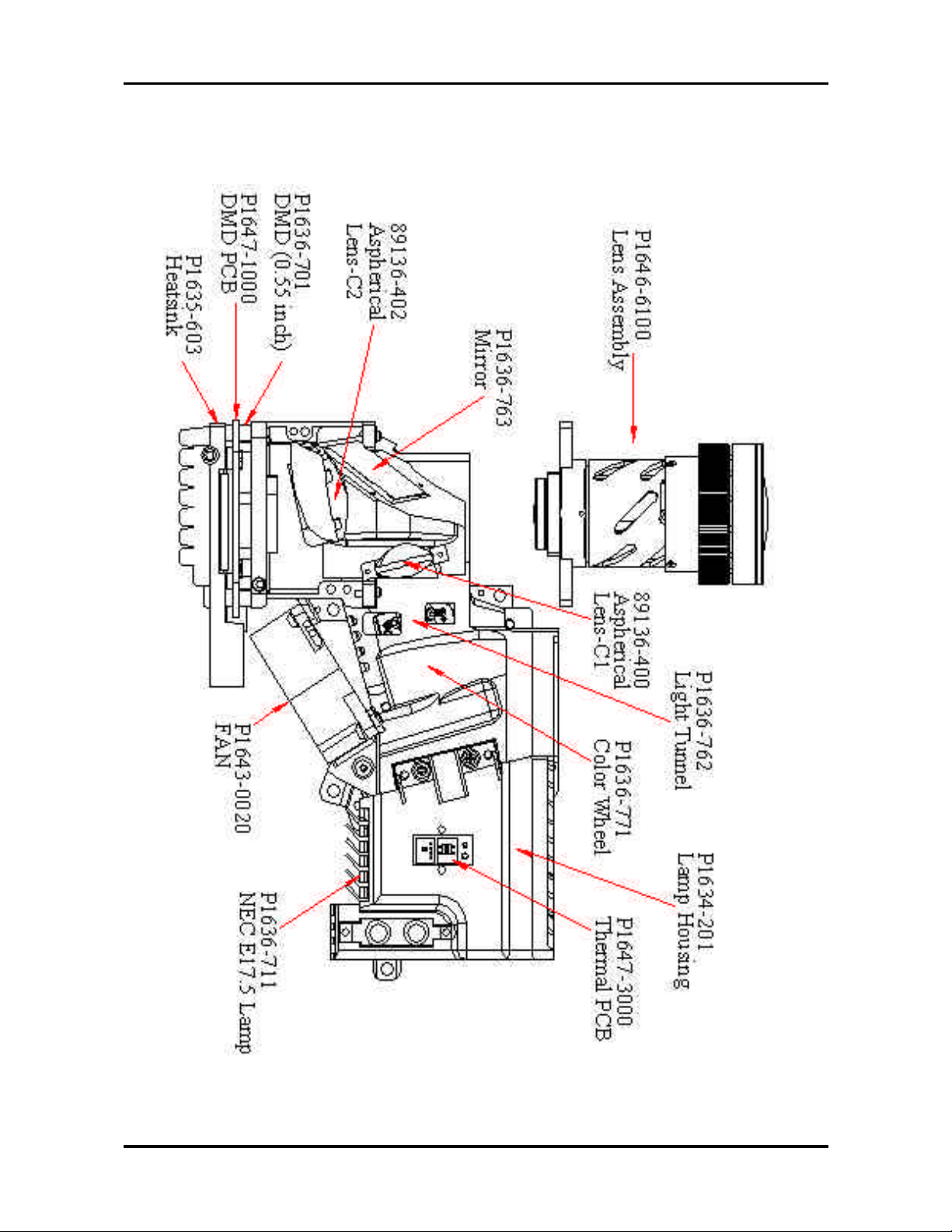
Optics-Con ceptual Drawing
Page 14
Chapter 2 8
Upgrading Procedure
Firmware Upgrade
This cha pter provide s the equipment needed, setup and upgrading procedure for
Firmware upgrade.
Chapter 2
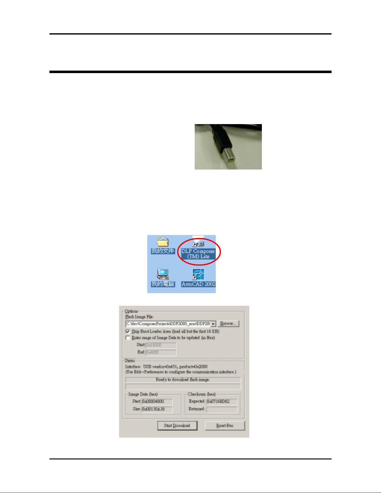
Setup Tool / Equipment
1. Computer
2. USB Cable (see right picture)
3. Power Coard
1. Connect Download Ca ble to proje ctor
2. Open burning programma (DLP Composer Lite)
Page 15
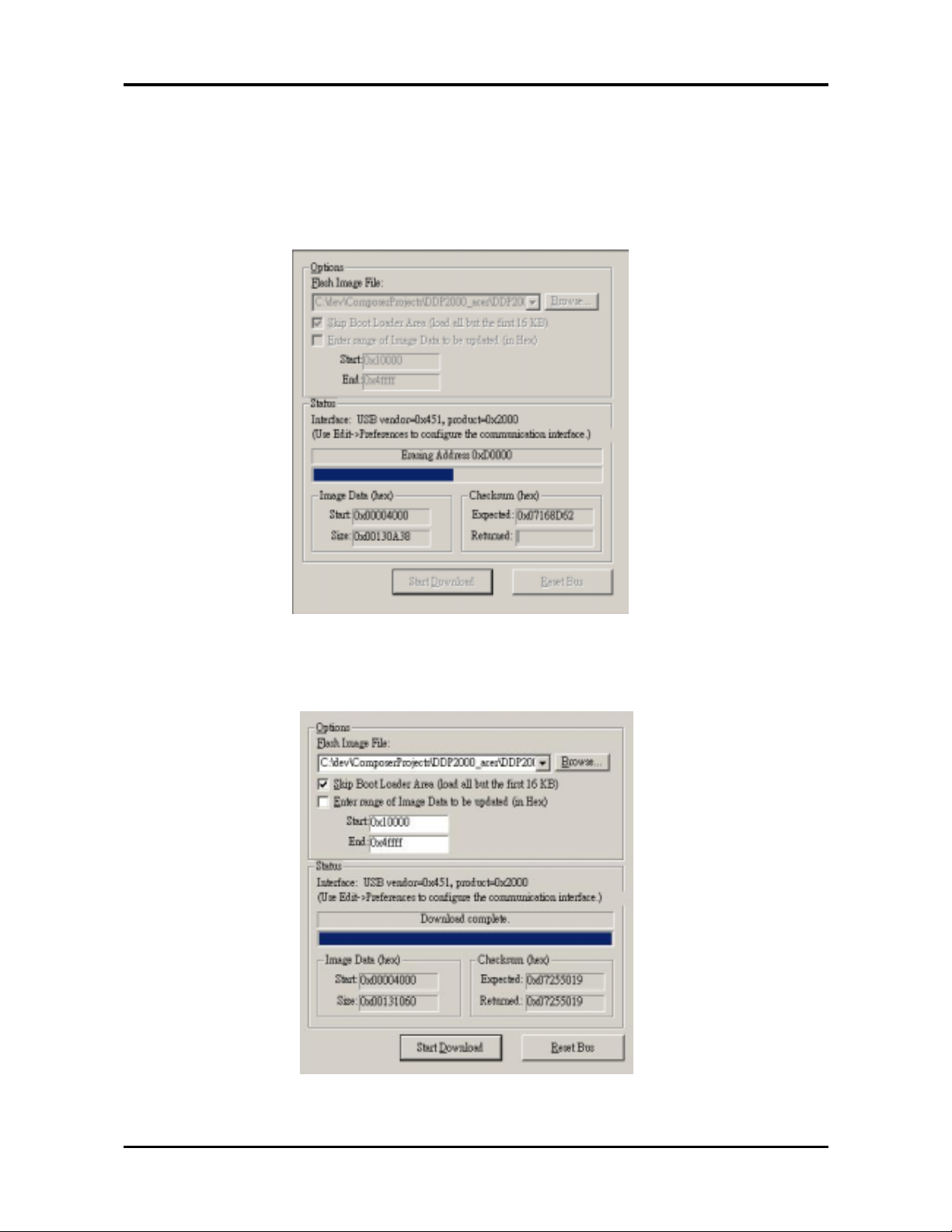
9 Cha pter 2
3. Pre ss Power a nd Menu button together a nd connect the power cord into the
projector . Tha n release these 2 bottoms .
4. Click the Start Download button and then start to burning of progra m .
5. Completion of Burning tha n remove Power Cord and Burning Cord .
Page 16
Chapter 3 10
Machine Disassembly and Replacement
This section provides disassembly procedures for PH112 DLP Projector. Before you begin any
of these procedures, be sure to turn off the power, computer system, and other attached devices;
then disconnect the power cable from the electronically outlet. Moreover, when you disassemble
the projector, be sure to put the screws in a safe place and separate them according to grouping.
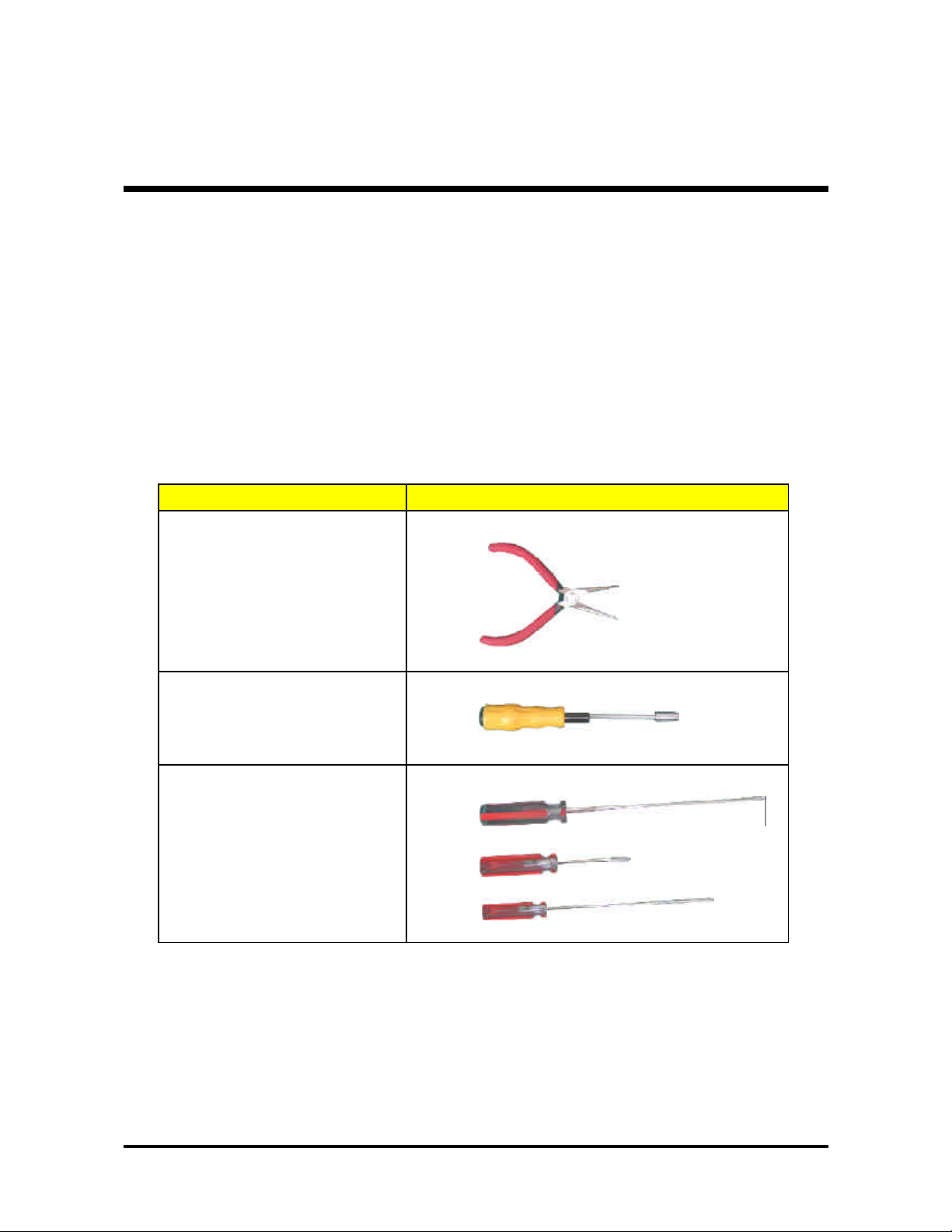
Tool Needed
Chapter
3
Item PHOTO
Long Nose Nipper
Hex Sleeves 5mm
Screw Bit (+) : 107
Screw Bit (+) : 101
Screw Bit (+) : 102
Page 17

11 Chapter 3
General Information
Before Yo u Begin
Before proceeding with the disassembly procedure, make sure that you do the following:
1. Turn off the power to the system and all peripherals.
2. Unplug the AC adapter and all power and signal cables from the system.
3. Wear Anti-static wrist strap.
Page 18
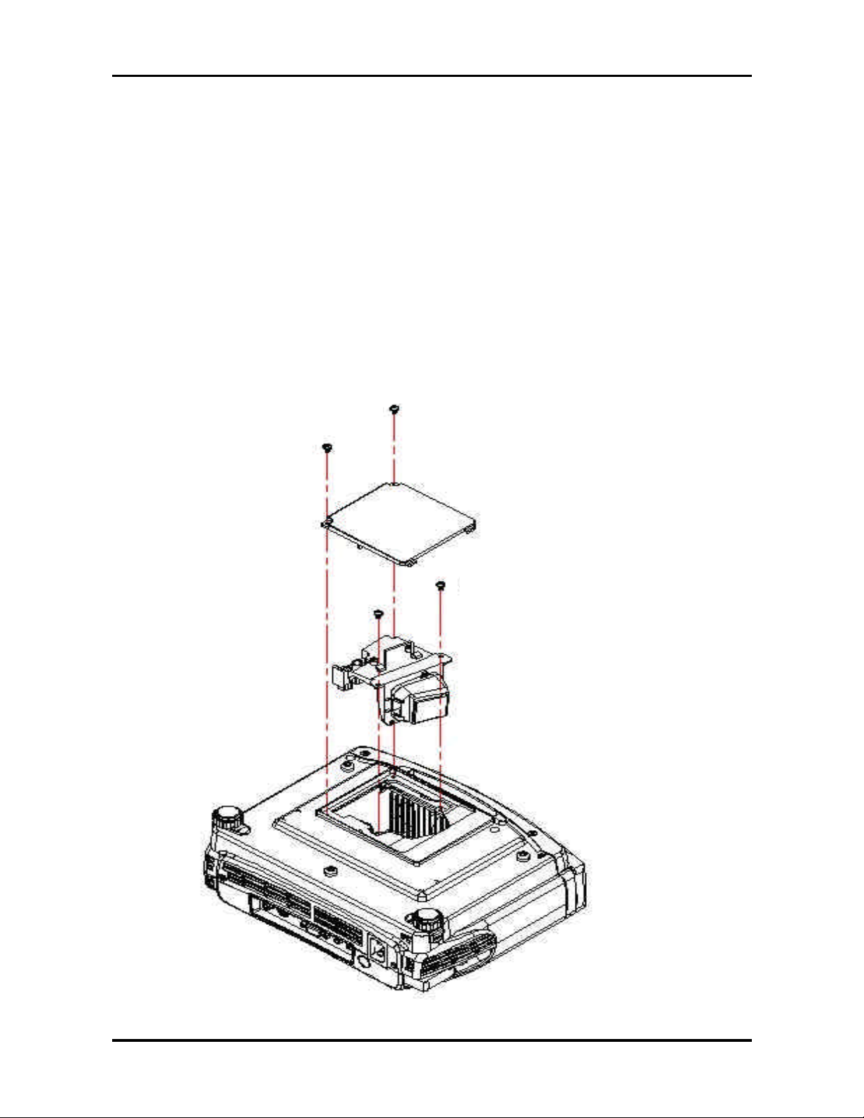
Chapter 3 12
1. Loosen two screws of Lamp Cover
2. Remove Lamp Cover
3. Loosen two screws of Lamp Module .
4. Grasp the lamp handle and pull out Lamp Module
p.s Related notice of replace lamp pls refer to the Lamp Specification section .
Disassemble Lamp Module
Note:Unplug all the cord before disaddembling the Projector.
01635-366*2
01635-366*2
Lamp Cover Assembly
Lamp Assembly
Page 19

13 Chapter 3
1. Loosen 4 screws of IO cover.
2. Remove IO cover
3. Loosen 2 screws of Back Cover
Disassemble IO Cover & Top Cover
1. Loosen the 2 screws of Top Cover.
2. Lift up Top Cover directly (Be careful there is a internal wire connect with the main board)
01635-D360-00 *2
01635-B730-00 *2
01635-B730-00 *2
P2038-1550-00
P2035-4510-99
82035-2510-00 *2
Page 20

Chapter 3 14
Disassemble Front Cover
Disassemble Speaker
01635-362 *2
02591-0014-00
02413-0016-00
1. Loosen the screws of Speaker.
2. Life up Speaker.
1. Loosen the 2 screws of Front Cover.
2. Lift up Front Cover directly(Be careful there are three internal wires connect with the main
board)
01635-B730-00 *2
Page 21

15 Chapter 3
Disassemble Front Fan
1. Lift up the Front f Fan Set from front cover directly.
Page 22

Chapter 3 16
Disassemble Front IR Board & IR Cover
P3634-7650-00
P2034-4520-98
01635-3610-00
02595-0029-00
P2447-5100
Page 23

17 Chapter 3
Disassemble Video IO
1. Loosen the screws of Back Cover
2. Loosen back cover.
3. Remove the Video IO.
01635-3610-00 *2
Page 24

Chapter 3 18
Disassemble Main Board
1. Loosen the four screws of Main Board
2. Unplug all wires on the board (Main Board PIN location of connectors pls refer to
Chapter 5 )
3. Remove Main Board
01635-3660-00 *4
P3635-0560-00
01635-3660-00
Page 25

19 Chapter 3
1. Lossen the screw of Back IR board.
2. Remove the Back IR board
3. Lossen the six screws of Ballast Module
4. Unplug all wires on Ballast Module (Ballast Board PIN location of connectors pls refer
to Chapter 5 )
5. Remove the Ballast Module.
Disassemble Ballast Module & Back IR
P4543-1016
01635-3610-00 *2
01635-3660-00 *2
Unplug from Power Module 2Pin Connector
Unplug from Lamp Module Connector
Page 26

Chapter 3 20
Disassemble Optical Engine
1. Lossen the four screws of Optical Engine
2. Remove the Optical Engine .
01635-A010-00 *4
Page 27

21 Chapter 3
Disassemble Back Cover
1. Loosen the screw of AC Inlet & remove the ring.
2. Remove the Back Cover.
3. 01635-7050-00
4. 01635-A080-00
P5844-0007
Page 28

Chapter 3 22
Disassemble Ba ck IR Cover, AC Outlet
1. Take out the AC Inlet.
2. Take out the Back IR Cover.
02595-0028-00
P2034-4530-98
P2034-4640-00
Page 29

23 Chapter 3
Disassemble Power Module
1. Unplug the wire.
2. Loosen the five screws of Power Module
3. Remove the Power Module.
01635-3610-00 *5
02595-0063-00
b
c
d
e
a
Page 30
Chapter 3 24
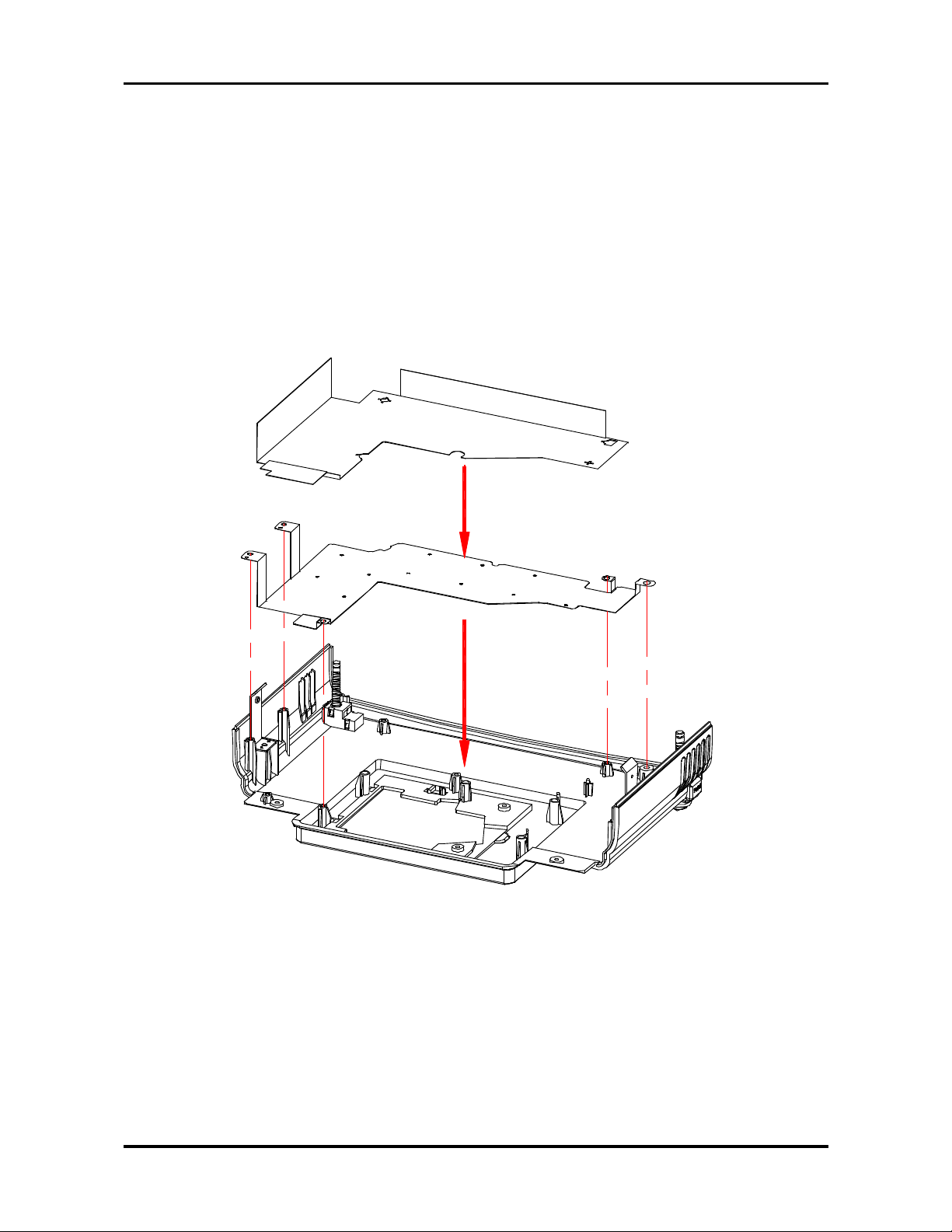
Disassemble Ground Plate & Mylar
1. Lift up the Groung Plate.
2. Then lift up the Mylar.
2. P2035-0500-00
3. P2038-0520-00
Page 31

25 Chapter 3
P1647-1000
01635-C01 *4
P1635-603
P1638-106*2
83034-040
P1638-105
Disassemble Heatsink & DMD Board
1. Loosen the four screws of Heatsink.
2. Tear off the EMI Pad
3. Remove the Heatsink. (Do not Suggest to tear off Thermal Pad and DMD Pad
on Heatsink unless they are damaged)
4. Lift up the DMD Board.
P3447-6000
P1635-6030-00
Page 32

Chapter 3 26
DMD Assembly
02475-0003-10
P1636-701
right angle to
right angle
Disassemble DMD Assembly & DMD
1. Lift up the DMD Assembly
2. Lift up the DMD
02093-0007-00
Page 33

27 Chapter 3
Disassemble Thermal Board
1. Loosen the screw of Thermal Board
2. Remove the Thermal Borad
01635-3530-00
P2235-0000-00
Page 34

Chapter 3 28
P1643-0020
P0335-101 *3
stick on top of joint
P1638-102
and can not protrude
screw the two
this side
screws first
Disassemble Optical Engine Fan
1. Loosen the three screws of Fan
2. Remove the Optical Engine Fan
02394-0011-00
Page 35

Chapter 4 30
Troubleshooting
This chapter provides technicians and people who have an electronic background a primary
description about maintaining the product. Moreover, you can get the appropriate operation
to solve some complicated problems of component repairing and professional problems.
The Troubleshooing se ction focus on below items:
1. Video Signal Troubleshooting
2. Operation Function T roubleshooing
3. Power Source T roubleshooting
Chapter 4
Page 36

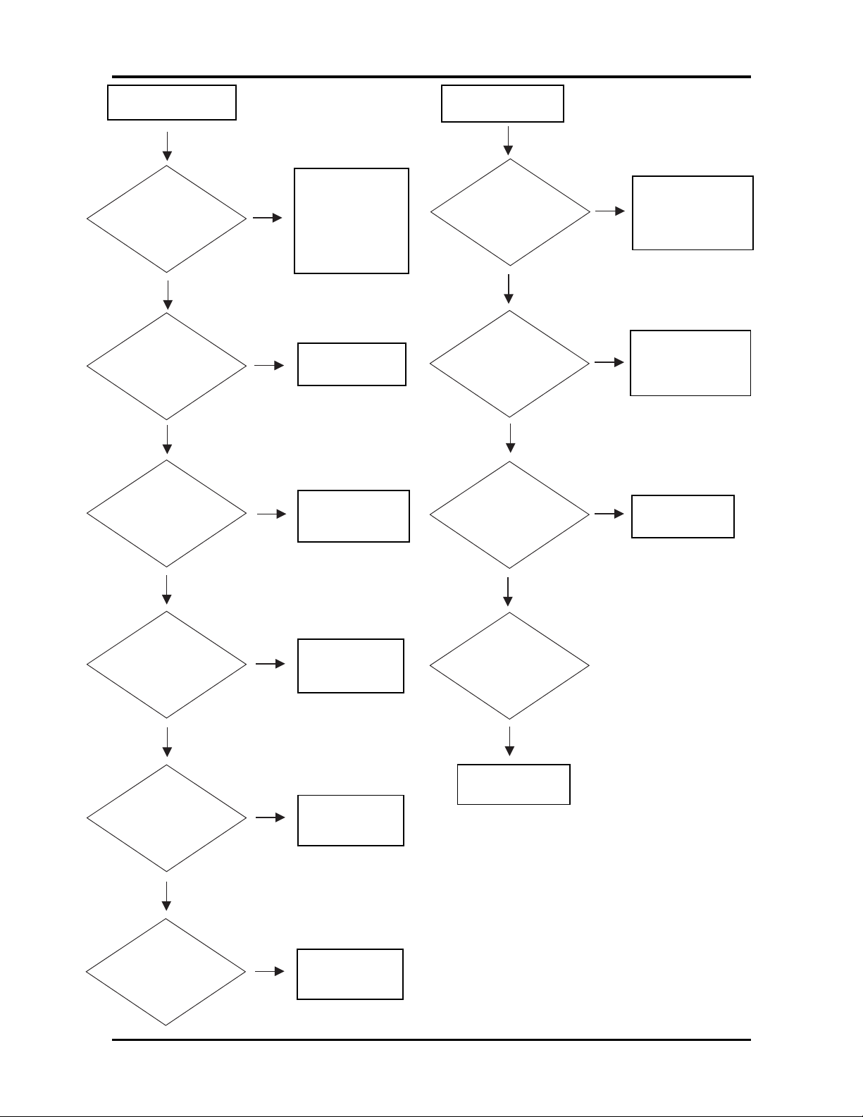
31 Cha pter 4
Video Signal
Computer
No Signal
Check
Source
Turn on
Source
Check
Cable
Replace
Cable
Computer
Mode
Input
Change to
Computer
Mode
Change Main
Board
NG
NG
NG
Video
No Signal
Check
Source
Turn on
Source
Check
Cable
Replace
Cable
Video
Mode
Input
Change to
Video Mode
OK
NG
OK
OK
NG
NG
OK
OK
OK
Change Main
Board
Page 37
Chapter 4 32
Fail to light up
Check
La mp
Look up user
manual ,a nd
follow indicative action
Check
Fan
Replace Lamp
Check
Thermal
Sensor
Replace Thermal Sensor
Check
LED indication
Replace Fa n
OK
NG
OK
OK
OK
NG
NG
NG
Repla ce Main
Board
NG
Check
Main Board
No Volume
Check
Speaker
Connector
Speaker
Connector
Become loose
Check
Speaker
Repla ce
Speaker
Check
Main
Board
Repla ce Main
OK
OK
OK
NG
NG
OK
Repla ce
Balla st
NG
Check
Ballast
Check
Top cover’s cable
Replace cable
or connect the
cable ba ck
OK
NG
Page 38

33 Cha pter 4
Color Missing
On Screen
C/W Cable
Connector
Check Cable
Connector
Check
Cable
Repla ce
Cable
Check Main
Board
Change Main
Board
OK
NG
OK
OK
OK
NG
NG
Change Optical
Engine
Page 39

Chapter 4 34
Operation Function:
Remote Control
Failure
Check
Battery
Level
Repla ce Battery
Check
Remote
Control
Repla ce Remote
Control
Check
IR
Replace IR
Main
Board Fail
OK
NG
OK
OK
NG
NG
Button Failure
Check
Button
Repla ce Button
Check
Keypad
Replace Keypad
Replace
Main Board
OK
OK
NG
NG
Check
Top cover’s cable
OK
NG
Replace cable
or connect the
cable back
Page 40

35 Cha pter 4
No Power Source
After Turning On
Check
La mp Cover
Switch
Replace Lamp
Cover or
Reassembly
Check
Power Cord
Check
Top Cover (key
cable..)
Replace
cable or key
Check
Power
Board
Replace M ain
Board
OK
NG
OK
OK
OK
NG
NG
NG
Replace
Power Board
NG
OK
Check
Main
Board
Power Source:
Repla ce Standby
Signal cable NG
Fan failure After
Turning On
Check
Fan
Connector
Fan Connector
Become loose
Check
Inner
Wires
Replace Inner
Wires
Check
Fan
Replace
Fan
Check
Main
Board
Replace
Main Board
OK
NG
OK
OK
NG
NG
NG
OK
Replace Power
Baord
Replace
Power Cord
Page 41

Chapter 4 36
Function Test and Alignment
Equipment Needed
T e st Condition
Page 42

37 Cha pter 4
langiSteserP cnyS noituloseR )zH(Vf )zH(Hf
AGV)-(V,)+(H008x046
065.13
277.73
575.73
583.34
AGVS)+(V,)-(H006x008
651.53
069.73
271.84
579.64
587.35
AGX)-(V,)-(H867x4201
064.84
075.65
5706
0846
583.86
AGXS)+(V,)+(H4201x08210646
Test Display Modes and Patterns
Compatible Modes
Page 43
Chapter 4 38
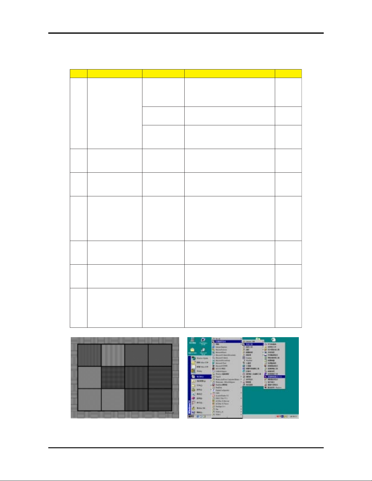
Function Test Display Pattern
metI tnetnoCtseT nrettaP noitacificepS krameR
1pukcehcesioN
serauqs21
PMB"serauqs21"ehttceleS.)1(
ynasierehtfikcehcotelif
foegatsehtgnirudsesion
ehtpugnimrawdna,nogninrut
.rotcejorp
1erugiF
serauqs21
ehtnoraeppasesionehT.)2(
nahtsselebdluohserauqs
.serauqseerht
1erugiF
rekcilf008
PMB"rekcilf008"ehttceleS.)3(
nodrowhcaeterusekaM.elif
tonnseodegamidetcejorpeht
.rekcilf
2erugiF
2pukcehctsuDkcalBlluF
elifPMB"kcalBlluF"ehttceleS)1(
ehtnoegamiehttcejorpot
timorfsretem8.1dnatS.neercs
.sniatsoneraerehterusnedna
3erugiF
3pukcehctsuDetihWlluF
elifPMB"etihWlluF"ehttceleS)1(
ehtnoegamiehttcejorpot
timorfsretem8.1dnatS.neercs
.sniatsoneraerehterusnedna
4erugiF
4pukcehcnoituloseR
dnakcalB
droWetihW
etihwdnakcalb"ehttceleS)1(
ehtesU.elifPMB"drow
detcejorpehttsujdaotrotcejorp
ezismumixamehtotegami
ekamdnaezismuminimdna
sidrowhcaeerus
htobrednuelbahsiugnitsid
.snoitidnoc
Fi erug5
5pukcehcrolocBGRBGR652
elifPMB"BGR652"ehttceleS)1(
foreddalrolocehtfikcehcot
rolocehtsehctamegamieht
.elifehtforeddal
erugiF6
6pukcehctsuDyarGlluF
elifPMB"yarGlluF"ehttceleS)1(
ehtnoegamiehttcejorpot
timorfsretem8.1dnatS.neercs
.sniatsoneraerehterusnedna
7erugiF
7
kcehcegakaelthgiL
pu
yradnuoB
emarF
"ehttceles,redlofehtnokcilC)1(
,elifPMB"emarFyradnuoB
ehtnonottubOTUAehtsserp
dnasenilehtfikcehc,rotcejorp
egamidetcejorpehtfosroloc
ehtnodetneserpsaraelcera
.elifPMB
8erugiF
12 squares Pattern (Figure 1) 800 flicker Pattern (Figure 2)
Page 44

39 Cha pter 4
Full Black Pattern (Figure 3) Full White Pattern (Figure 4)
Gray Pattern (Figure 7) Boundary Frame (Figure 8)
Black and White Word Pattern (Figure 5) 256RGB Pattern (Figure 6)
Page 45

Chapter 5 40
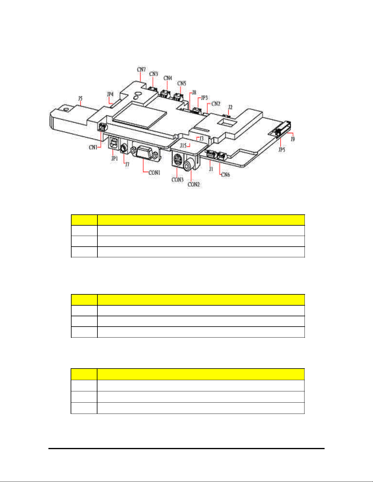
Main Board
Summariz e
Connector Description
CN1 IR
CN2 Keypad control
CN3 Fan
CN4 Fan
CN5 Fan
CN6 Fan
CN7 IR
J1 Ballast control
J2 Thermal
J3 Vidio & S-Video in
J5 DMD connector
J7 Phone jack stereo-R
J8 Color wheel
J9 Power in
J15 Vidio & S-Video in
JP1 USB
JP3 CW index
JP4 Firmware debug
JP5 Standby run
CON1 D-SUB
CON2 Video
CON3 S-video
Connector Information
Introduction
This section provides each connector location on boards, signal and function of each
board. They will be useful for your detecting the defective boards.
Chapter
5
Page 46
41 Chapter 5
The Locations of Connectors
PIN# Description
1
PWM
2
Control
3 GND
CN3 , CN4 , Cn5 : FAN
PIN# Description
1
12V_S1
2
FAN_FB3
3
GND_PWM3
J1 :Ballast Control
PIN# Description
1 IR 0
2
GND
3 +3.3 V
CN1 , CN7 : IR
Page 47

Chapter 5 42
PIN# Description
1
GND
2
GND
3 SP_R+
4
SP_R+
5 SP_R-
6
SP_R-
7
SP_L+
8 SP_L+
9
SP_L-
10 SP_L-
11
Keypad_PWR
12
Keypad_Menu
13 Keypad_Up
14
Keypad_Down
15 Keypad_Left
16
Keypad_Right
17
GND
18 GND
19
Power_LED
20 LED_SYS2
21
LED_Lamp1
22
LED_Lamp2
23 P3P3V_STBY_PWR
24
P3P3V_STBY_PWR
25 P3P3V_STBY_PWR
26
Key_Source
27
IR 1
28
Key_Auto
CN2 : Keypad Control
Page 48

43 Chapter 5
CON2 : Video
PIN# Description
1 CVBS
2
AGND
CON3 : S-Video
PIN# Description
1
AGND
2
AGND
3
SVDOY
4 SVDOC
PIN# Description
1
COMPVID
2
AGND
3 SVID_LUM
4
AGND
5
SVID_CHR
6
GND
7 + 3.3 V
8
+ 3.3 V
J3 , J15 : Video & S-Videop IN
PIN# Description
1 + 3.3 V
2
SCL
3
SDA
4
GND
J2 :Thermal
Page 49

Chapter 5 44
J7 : Phone jack Stereo-R
PIN# Description
1
GND
2 AINC_L
3
NC
4 AINC_R
5
NC
CON1 : D_SUB
PIN# Description
1 V- Red
2
V-Green
3
V-Blue
4
NC
5
AGND
6 AGND
7
AGND
8
AGND
9
+5V
10
DSUB_Detect
11 AGND
12 VSDA
13
H-Sync
14
V-Sync
15
VSCL
PIN# Description
1 CW CTR
2
CW Y3
3
CW Y2
4 CW Y1
J8 : Color Wheel
Page 50

45 Chapter 5
JP1 : USB
PIN# Description
1
+5V_STBY
2
GND
3 GND
4
+5V
5 +5V
6
GND
7
+13.5V
8 GND
9
+12.5V
10 GND
J9 : Power Supply
PIN# Description
1
NC
2
USB DATN
3 USB DATP
4
GND
5
GND
6 GND
PowerIn
PIN# Description
1
+3.3V
2 +3.3V
3
+3.3V
4 GND
JP3 : CW Index
PIN# Description
1
STBY_PWR
2 GND
JP3 : CW Index
Page 51

Chapter 5 46
PIN# Description
1
GND
2
GND
3
TMSI
4
TDO1_OUT
5
SYSRSTZ
6
TRSTZ
7
TDI
8
TMS2
9
TCK
10 RTCK
11 TDO2
12 ICE_RSTZ
13 TRACEPKT15
14 TRACEPKT14
15 TRACEPKT13
16 TRACEPKT12
17
TRACEPKT11
18
TRACEPKT10
19
TRACEPKT9
20
TRACEPKT8
21
TRACEPKT7
22
TRACEPKT6
23
TRACEPKT5
24
TRACEPKT4
25 TRACEPKT3
26 TRACEPKT2
27 TRACEPKT1
28 TRACEPKT0
29 TRACECLK
30 TRACESYNC
31
PIPESTAT0
32
PIPESTAT1
33
PIPESTAT2
34
+3.3V
35
+3.3V
36
+3.3V
JP4 : FirmWare Debug
Page 52

47 Chapter 5
Power Board
Summarize
Connector Description
CN101 AC Inout
CN201 +380V Output
CN301 DC Output
The Locations of Connectors
PIN# Description
1
Line
2
NEUTRAL
CN101 : AC Inout
Page 53

Chapter 5 48
PIN# Description
1 +380V
2
GND
CN201 : +380V Output
PIN# Description
1
+5V_STBY
2
GND
3
GND
4
+5V
5
+5V
6 GND
7 +13.5V
8 GND
9 +12.5V
10 GND
11 GND
12 STBY_CTRL
CN301 :DC Output
Page 54

49 Chapter 5
Ballaster Board
Summarize
Connector Description
X1 Power input
X2 SCI & Flag
X3 Connection to lamp
X2: SCI & Flag
X1 : Power input
PIN# Description
1 DC Input voltage
3
GND
The Locations of Connectors
PIN# Description
1 Flag/TxD (coll.)
2
Flag/TxD (emitter)
3
Common+ (anodes)
4
SCI/Sync (cath.)
5 RxD (cath.)
X3: Connection to lamp
PIN# Description
1 LAMP
4
LAMP
Page 55

Chapter 6 50
FRU (Field Repla ce a ble Unit) List
This cha pter gives you FRU ( Field Repla ce able Unit ) listing in global configuration of PD-112.
Refer to this chapter whenever ordering for parts to repair or for RMA ( Return Merchandise
Authorization ). Plea se note that WHEN OR DERING FRU PARTS, you should check the most
up-to-date information available on your regional web or cha nnel. For whatever re a son s a part
number change is ma de, it will not be noted on the printed Service Guide. For Acer AUTHORIZED SER VICE PROVIDERS, Acer office may have a DIFFERENT part number code from
those given in the FRU list of this printed Service Guide. You MUST use the local FRU list provided by your regional Acer of fice to order FRU parts for repair a nd service of customer machines.
NOTE : To scrap or to return the defective parts, you should follow the local government
ordinance or regulation s on how to dispose it properly, or follow the rules set by your
regional Acer office on how to return it.
Chapter 6
Page 56

51 Cha pter 6
.oN otohP emaNtraP N/P
1draoBniaM100-4876P
2draoBtsallaB200-4876P
3draoBrewoP300-4876P
4draoBDMD0006-7443P
5draoBRItnorF0015-7442P
6draoBRIkcaB1015-7423P
7TEKCARBROSNES00-0000-5322P
8revocpoT4000-4876P
9revocmottoB5000-4876P
01revoctnorF6000-4876P
FRU List
Page 57

Chapter 6 52
.oN otohP emaNtraP N/P
11revoCkcaB7000-4876P
21revoCRItnorF00-0654-4302P
31EGNOPSOI00-0551-8302P
41etalPOI99-0154-5302P
51revoCpmaL4001-4436P
61tekcoSnip302DMD01-3000-57420
71eludoMpmaL8000-4876P
81enignElacitpO9000-4876P
91)hcni55.0(DMD00-7000-39020
02teSnaFtnorF6001-5476P
Page 58

53 Cha pter 6
.oN otohP emaNtraP N/P
12naFenignE10-1100-49320
22etalPdnuorG00-0050-5302P
32ralyM00-0250-8302P
42knistaeHDMD00-0306-5361P
52ETALPEDIS00-0250-5302P
62revoCneL00-A264-4302P
72rekaepS00-6100-31420
82
niP3eriW
RI-FotB/M
00-9200-59520
92
elbaCCCFeriW
revoCpoTotB/M
00-4100-19520
03
telnICAeriW
rewoPottelnICA
00-8200-59520
Page 59

Chapter 6 54
.oN otohP emaNtraP N/P
13
niP3eriW
RI-BotB/M
00-7200-59520
23
niP5eriW
tsallaBotB/M
00-0300-59520
33
niP2eriW
rewoPottsallaB
00-9100-59520
43
niP4eriW
BM
00-8100-59520
53
niP2+01-niP21eriW
rewoPotB/M
00-3600-59520
63
73
83
93
04
 Loading...