

Page 1
SERVICE MANUAL
P7280/P7270I/P7280 Refresh/P7270I Refresh/P7290
Date Revise Version Description
2008.1.24 V1.0 Initial Issue
2008.6.30 V2.0 Add P7280 Refresh/P7270i Refresh
Add Waveform Download in Chapter 5, add Defaul
2008.10.10 V3.0
2009.05.05 V4.0
2009.07.31 V5.0 Add P7290 model
Copyright July, 2009 All Rights Reserved P/N: 36.89K01G001
Language in Chapter 6, and modify Chapter 4 and
Appnendix B
1. Add the “Universal Password Failure” in Chapter 3
2. Revise FW Upgrade Procedure’s method in Chapter 5
3. Modify the title of 6-6 in Chapter 6
SI : TSE: Check: Approved:
Page 2

Preface
This manual is applied to P7280/P7270I/P7280 Refresh/P7270I Refresh/P7290 projection
system. The manual gives you a brief description of basic technical information to help in
service and maintain the product.
Your customers will appreciate the quick response time when you immediately identify
problems that occur with our products. We expect your customers will appreciate the
service that you offer them.
This manual is for technicians and people who have an electronic background. Please
send the product back to the distributor for repairing and do not attempt to do anything that
is complex or is not mentioned in the troubleshooting.
Notice: The information found in this manual is subject to change without prior notice. Any
subsequent changes made to the data herein will be incorporated in future edition.
P7280/P7270I/P7280 Refresh/P7270I Refresh/P7290 Service Manual
Copyright July, 2009
All Rights Reserved
Manual Version 5.0
P7280/P7270I/P7280 Refresh/P7270I Refresh/P7290
Condential
i
Page 3
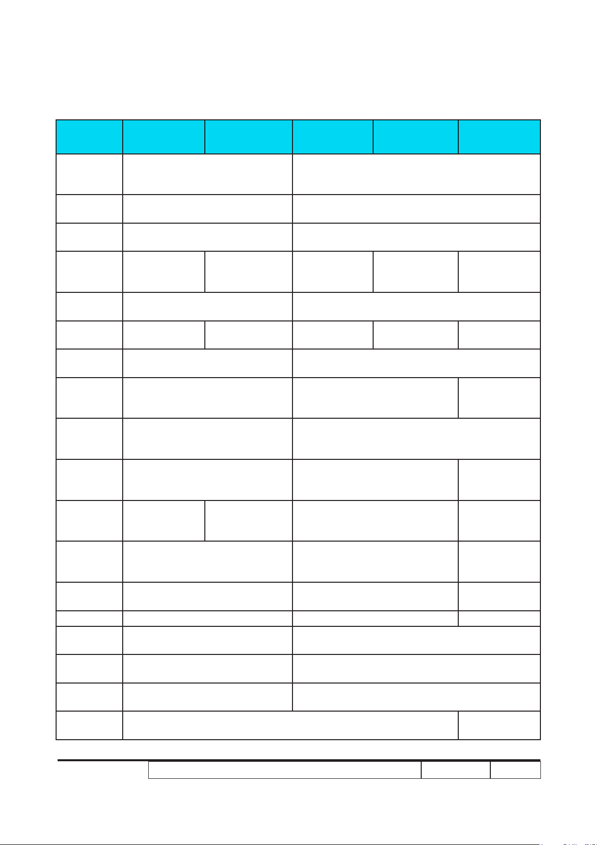
P7270I/P7280/P7270I Refresh/P7280 Refresh/P7290Refresh/P7290/P7290
Comparison List
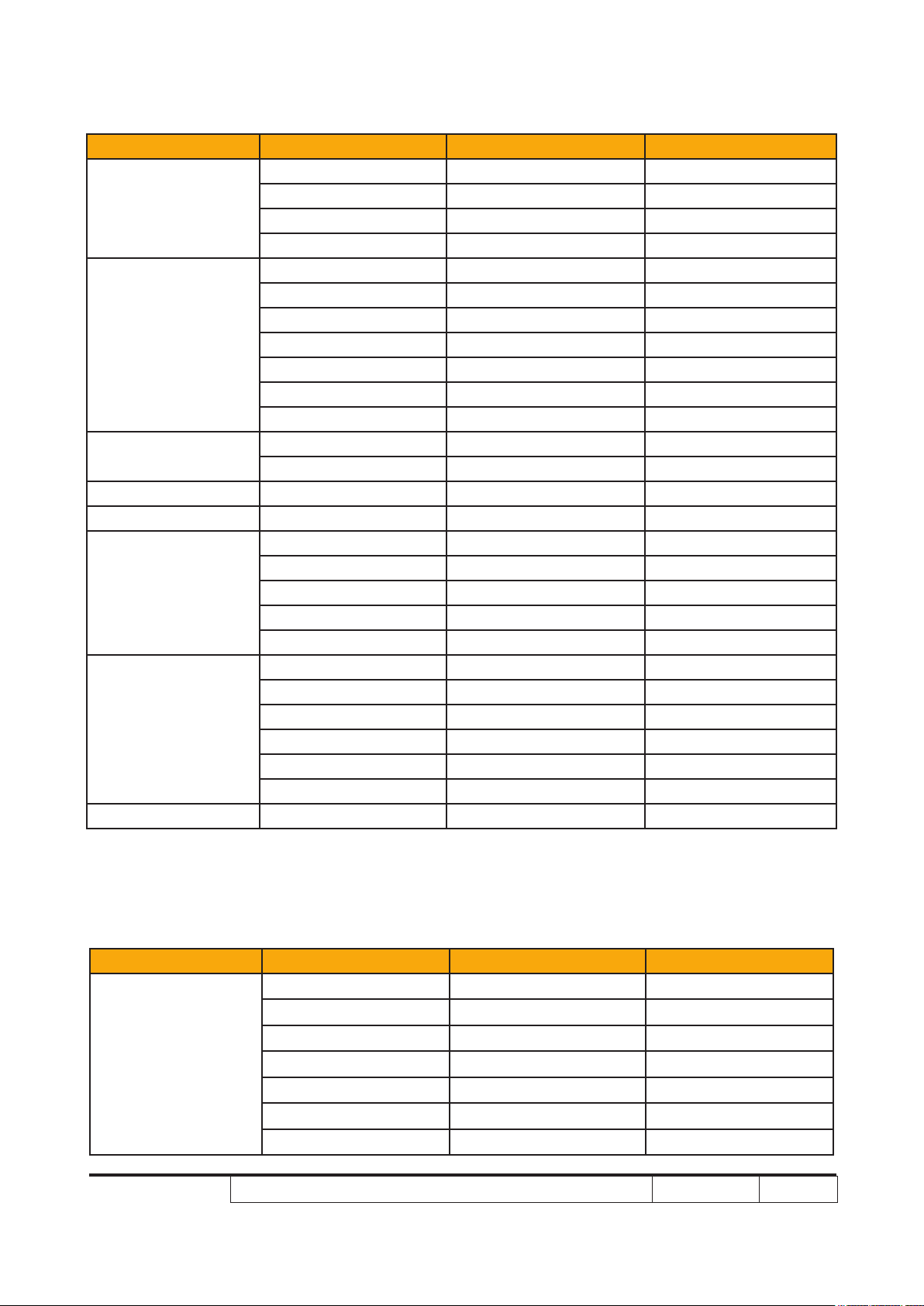
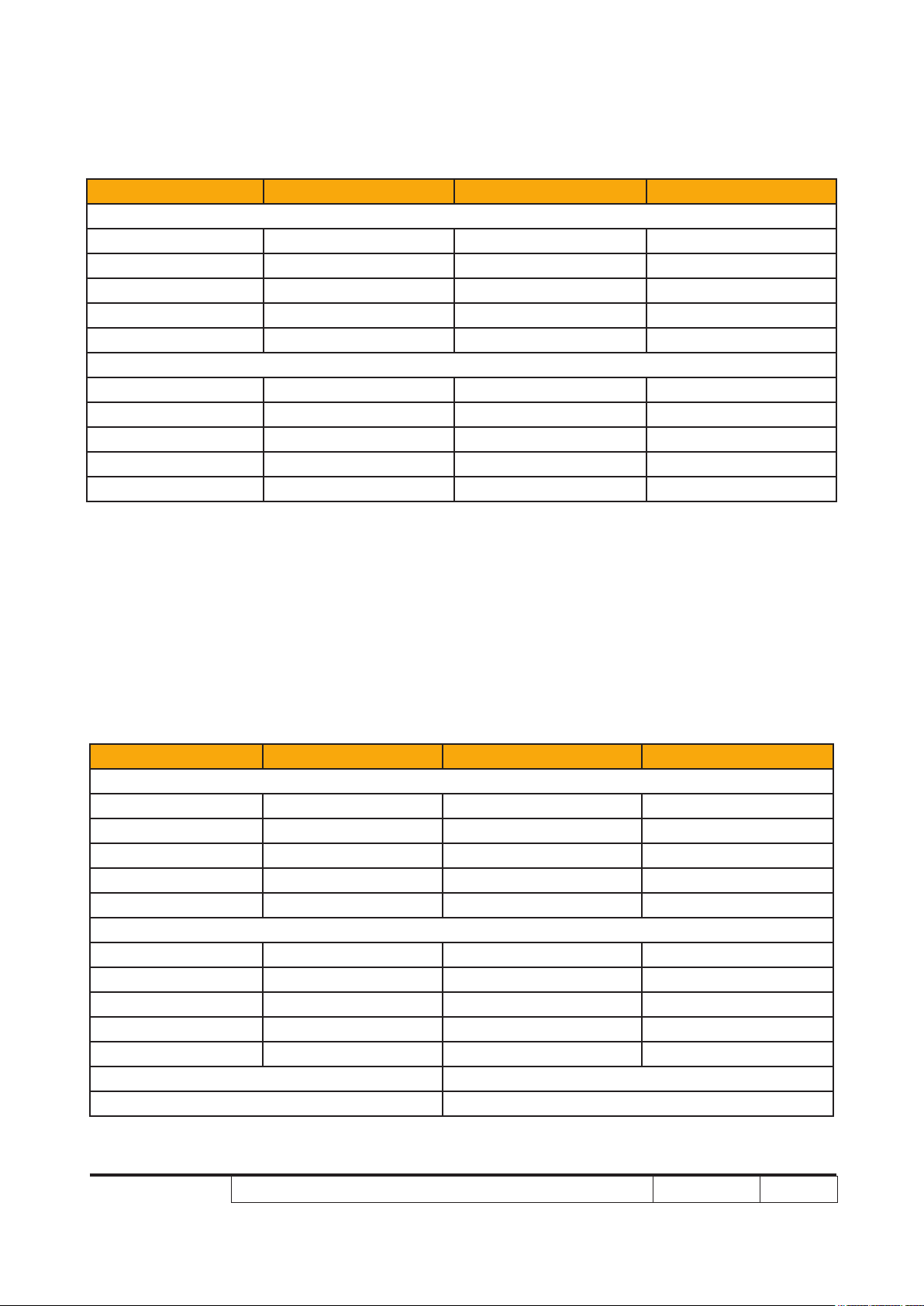
Parts P7270I P7270I Refresh P7280 P7280 Refresh P7290
LAMP
WARNING
LABEL
THERMAL
SWITCH
DMD
BLOWER
COLOR
WHEEL
MODULE
ENGINE
MODULE
MAIN BD
MODULE
I/O BD
MODULE
BOTTOM
COVER
MODULE
BACK
COVER
MODULE
TOP
COVER
MODULE
LAMP
DRIVER
MODULE
INTERLOCK
SWITCH
LAMP
MODULE
LVPS 75.85H15G001 75.88B07G001 75.8FA01GP01
WIRELESS
MODULE
HANDY
DRIVE
EXTERNAL
ANTENNA
LAMP
BLOWER
70.87Y30GR01 70.89K24GR01 70.87Y30GR01 70.89K24GR01 70.8FA16GR01
70.87Y32GR01 70.87Y43GR01 70.89K17GR01 70.89K25GR01 70.8FA19GR01
70.87Y39GR01 70.87Y42GR01 70.89K22GR01 70.8FA17GR01
35.88E01G002 35.88B04G002
43.87Y01G001 43.89K01G001
N/A 49.89K01G001
70.87Y31GR01 70.89K16GR01
70.87Y33GR01 70.89K18GR01
70.87Y35GR01 70.89K19GR01 70.8FA18GR01
70.87Y37GR01 70.89K20GR01
70.87Y38GR01 70.89K21GR01 70.8FA15GR01
75.87Y04G001 75.89K01G001 75.8FA03G001
SP.87Y01GC01 SP.89K01GC01 SP.8FA01GC01
75.87Y02G002 N/A
75.87Y15G002 N/A
75.87Y11G001 N/A
49.87C01G001 49.8EA01G001
P7280/P7270I/P7280 Refresh/P7270I Refresh/P7290
Condential
ii
Page 4

Table of Content
Chapter 1 Introduction
Highlight 1-1
Compatible Mode 1-5
Product Overview 1-9
Chapter 2 Disassembly Process
Equipment Needed & Product Overview 2-1
Disassemble Top Cover Module 2-2
Disassemble Lamp Module 2-4
Disassemble Wireless Module (only for P7270I/P7270I
Refresh) 2-5
Disassemble Top Shielding Module 2-7
Disassemble Zoom Ring and Focus Ring Module 2-10
Disassemble Back Cover Module 2-11
Disassemble Left and Right Cover Module 2-12
Disassemble Front Cover Module 2-13
Disassemble Front Shielding 2-14
Disassemble Main Board Module and I/O Board Module 2-15
Disassemble Shielding Module 2-17
Disassemble LVPS Module 2-19
Disassemble Fan Module 2-21
Disassemble Engine Module 2-22
Disassemble Color Wheel Module 2-24
Disassemble DMD Board and DMD Chip 2-25
Disassemble Lamp Blower Module 2-26
Disassemble ROD Blower Module 2-27
Disassemble ROD Duct Module 2-28
Disassemble System Duct Module 2-29
P7280/P7270I/P7280 Refresh/P7270I Refresh/P7290
Condential
iii
Page 5

Disassemble Lamp Driver Module 2-30
Disassemble Lamp Driver Holder (only for P7270I/
P7270I Refresh) 2-31
Disassemble Interrupt Switch Module 2-32
Disassemble Elevator Module 2-33
Rod Adjustment 2-34
Re-write Lamp Usage Hour 2-35
Assemble Elevator Module 2-36
Assemble Interrupt Switch Module 2-37
Assemble Lamp Driver Holder (only for P7270I/
P7270I Refresh) 2-37
Assemble Lamp Driver Module 2-38
Assemble System Duct Module 2-39
Assemble ROD Duct 2-40
Assemble ROD Blower Module 2-40
Assemble Lamp Blower Module 2-41
Assemble DMD Board and DMD Chip 2-41
Assemble Color Wheel Module 2-42
Assemble Thermal Switch 2-42
Assemble Engine Module 2-43
Assemble Fan Module 2-44
Assemble LVPS Module 2-45
Assemble Shielding Module 2-47
Assemble Main Board Module and I/O Board Module 2-49
Assemble Front Shielding 2-51
Assemble Front Cover Module 2-52
Assemble Left and Right Cover Module 2-53
Assemble Back Cover Module 2-54
Assemble Zoom Ring and Focus Ring Module 2-55
P7280/P7270I/P7280 Refresh/P7270I Refresh/P7290
Condential
iv
Page 6

Assemble Top Shielding Module 2-56
Assemble Wireless Module (only for P7270I/P7270I Refresh)2-58
Assemble Lamp Module 2-60
Assemble Top Cover Module 2-61
Chapter 3 Troubleshooting
LED Lighting Message 3-1
Main Procedure 3-2
Beep Sound 3-6
Chapter 4 Function Test & Alignment Procedure
Test Equipment Needed 4-1
Service Mode 4-1
OSD Reset 4-1
Test Condition 4-2
Test Inspection Procedure 4-3
PC Mode 4-4
Video Performance 4-7
Optical Performance Measure 4-8
Others 4-10
WLAN and LAN Signal Test(only for P7270I/P7270I Refresh) 4-11
Chapter 5 Firmware Upgrade
Equipment Needed 5-1
DLP Composer Lite Setup Procedure 5-2
USB Driver Upgrade Procedure 5-4
Firmware Upgrade Procedure 5-5
Waveform Download (for P7280 Refresh/P7270I Refresh
/P7290) 5-8
P7280/P7270I/P7280 Refresh/P7270I Refresh/P7290
Condential
v
Page 7

Chapter 6 EDID Upgrade
EDID Introduction 6-1
Equipment Needed 6-2
Setup Procedure (VGA1, VGA2, DVI) 6-3
EDID Key-In Procedure 6-4
Setup Procedure (HDMI) 6-7
Un-lock SNID and Default Language Reset
(for P7280 Refresh/P7270I Refresh/P7290) 6-10
Appendix A
Exploded Overview I
Appendix B
SerialNumberSystemDenition I
Appendix C
RS232 function command summary table I
PCBACodeDenition II
P7280/P7270I/P7280 Refresh/P7270I Refresh/P7290
Condential
vi
Page 8
Chapter 1
Introduction
1-1 Highlight
No Item Description
1 Dimensions (W x D x H) ● 403.6 (W) x 315.4 (D) x 119.8 (H) mm
2 Weight
3 Cooling System
4 Lamp Housing
5 DMD Chip ● TI DMD 0.7" 12° LVDS XGA Digital Mirror Device (DC3)
6 Number of active dots ● 1024 (H) x 768 (V)
7 Power Supply
● P7270I Refresh/P7270I/P7290: 12.2 lbs/5.5 kg
● P7280 Refresh/P7280: 12.4 lbs/5.6 kg
● Air Tunnel Flow
● Cooling fans with system optimized acoustic
● Temperature control circuits with adaptive fan rotational
speeds
● Maximum touch temperature follows UL60950-1
● Lamp assembly could be changed by customer himself,
but should read the user manual for instruction in advance.
● Lamp assembly should be provided by Coretronic and
distribute through authorized agencies
● Universal AC 100 – 240 V ~ 50-60 Hz with PFC input
● Variance FAN speed control (Depends on temperature
variant)
● P7270I Refresh/P7270I (280W):
Normal mode: 400W+/-10%@110VAC
ECO mode: 330W+/-10%@110VAC
Standby< 5W (without wireless module)
Standby< 13W (with wireless module)
(Wireless module stand-by mode < 8W)
8 Power Consumption
P7280/P7270I/P7280 Refresh/P7270I Refresh/P7290
● P7280 Refresh/P7280 (330W):
Normal mode: 450W+/-10%@110VAC
ECO mode: 380W+/-10%@110VAC
Standby< 5W (without wireless module)
● P7290:
Normal mode: 460W (without wireless module)@110Vac
ECO mode: 385W (without wireless module)@110Vac
Standby < 1W (without wireless module)
Condential 1-1
Page 9
No Item Description
● Hsync Frequency 30 k~ 100 kHz
● Vsync Frequency 56~ 85 Hz (for P7280/P7270I/
P7280 Refresh/P7270I Refresh)
● Vsync Frequency 50~ 85 Hz (for P7290)
● Video Signal RGB (PC)
Analog RGB 0.7Vp-p, 75 ohm, Separate TTL H,V Sync
9 Input signal spec
10 Video Compatibility
Analog RGB 1Vp-p, 75 ohm, Sync. On Green signal
Analog RGB 0.7Vp-p, 75 ohm, Composite TTL Sync.
● Video
Composite video 1Vp-p,75 ohm
S-video Luminance 0.714Vp-p, 75 ohm
S-video Chrominance 0.286Vp-p, 75 ohm
Component video 1Vp-p, 75 ohm
● Standards :
NTSC: M (3.58MHz), 4.43 MHz
PAL: B, D, G, H, I, M, N
SECAM: B, D, G, K, K1, L
HDTV: 720p, 1080i, 1080p
EDTV: 480p, 576p
SDTV: 480i, 576i
● Two 8-Ohm internal speakers
11 Audio
12 Lamp
13 Throw Distance ● 1.5m~ 10m
14 Throw Ratio ● 1.57~ 1.89: 1 @ 60”
● 3 Watts
● Input sensitivity 0.5Vrms
● 280W for OSRAM E20.6 Lamp @normal operation
(for P7270I Refresh/P7270I)
● 330W for Philips Lamp @normal operation
(for P7280 Refresh/P7280)
● 350W for Philips Lamp @normal operation (for P7290)
P7280/P7270I/P7280 Refresh/P7270I Refresh/P7290
Condential
1-2
Page 10
No Item Description
● Engineering spec:
• For P7270I Refresh/P7270I (280W):
Typical: 3420 lumens
Minimum: 3040 lumens
(Compliance with IS021118 criteria)
• For P7280 Refresh/P7280 (330W):
Typical: 4050 lumens
Minimum: 3600 lumens
15 Brightness
(Compliance with IS021118 criteria)
• For P7290 (350W)
Typical 4500 ANSI Lumens
Minimum 4000 ANSI Lumens
(Compliance with ISO21118 brightness criteria)
● Marketing spec:
• 3800 lumens (for P7270I Refresh/P7270I)P7270I Refresh/P7270I)
• 4500 lumens (for P7280 Refresh/P7280)P7280 Refresh/P7280)
• 5000 lumens (for P7290)
● Engineering spec:
• For P7280/P7270I/P7280 Refresh/ P7270I Refresh:
2100 : 1 Full White and Black (Typical)
1500 : 1 Full White and Black (Minimum)
16 Contrast
17 Uniformity
• For P7290:
2700 : 1 Full White and Black (Typical)
1900 : 1 Full White and Black (Minimum)
● Marketing spec:
• 2200:1 (P7280/P7270I/P7280/P7270I/P7280 Refresh/ P7270I Refresh)
• 3150:1 (for P7290)
● Engineering spec:
• 60% Japan standard (Minimum) (for P7280/P7270I/P7280
Refresh/ P7270I Refresh
• 65% Japan standard (Minimum) (for P7290)
• 80% Japan standard (Typical)
● Marketing spec:
• >85%
P7280/P7270I/P7280 Refresh/P7270I Refresh/P7290
Condential
1-3
Page 11
No Item Description
● Six segments
● 7200 rpm @ CW 2X
● 9000 rpm @ CW 3X, PAL 50Hz (for P7270I Refresh/P7280
18 Color Wheel
Refresh/P7290)
● Segment Angle: R90B82W42C28G90Y28
(for P7280/P7270I/P7280Refresh/P7270I Refresh)
● Segment Angle: R81Y41G84C31W52B71 (for P7290)
● for 0~ 2500 ft, 5~ 35 °C
19 Operation temperature
20 Storage temperature ● -20°C~ 60°C
21 Lamp life
● for 2500~ 5000 ft, 5~ 30 °C
● for 5000~ 10000 ft, 5~ 25 °C
● 2000 hours min, 50% survival rate (Normal mode)
(for P7280/ P7270I/P7280 Refresh/ P7270I Refresh)
1500 hours min, 50% survival rate (Normal mode) (for P7290)
● 2500 hours min, 50% survival rate (Eco mode)
P7280/P7270I/P7280 Refresh/P7270I Refresh/P7290
Condential
1-4
Page 12
1-2 Compatible Mode
A. VGA Analog
1. VGA Analog - PC Signal
Compatibility Resolution V-Sync [Hz] H-Sync [KHz]
640x480 60 31.50
640x480 72 37.90
VGA
SVGA
XGA
SXGA
QuadVGA
SXGA+ 1400x1050 60 65.30
UXGA 1600x1200 60 75.00
Power Mac G4
640x480 75 37.50
640x480 85 43.30
720x400 70 31.50
720x400 85 37.90
800x600 56 35.10
800x600 60 37.90
800x600 72 48.10
800x600 75 46.90
800x600 85 53.70
832x624 75 49.73
1024x768 60 48.40
1024x768 70 56.50
1024x768 75 60.00
1024x768 85 68.70
1152x864 70 63.80
1152x864 75 67.50
1152x864 85 77.10
1280X1024 60 63.98
1280X1024 72 76.97
1280X1024 75 79.98
1280X1024 85 91.10
1280x960 60 60.00
1280x960 75 75.23
640x480 66.6(67) 34.93
800x600 60 37.90
1024x768 60 48.40
1152x870 75 68.68
1280x960 75 75.00
P7280/P7270I/P7280 Refresh/P7270I Refresh/P7290
Condential
1-5
Page 13
Compatibility Resolution V-Sync [Hz] H-Sync [KHz]
640x480 60 31.35
640x480 66.6(67) 34.93
PowerBook G4
i Mac DV (G3) 1024x768 75 60.00
800x600 60 37.90
1024x768 60 48.40
1152x870 75 68.68
1280x960 75 75.00
2. VGA Analog - Extended Wide timing
Compatibility Resolution V-Sync [Hz] H-Sync [KHz]
1280x768 60 47.80
1280x768 75 60.30
1280x768 85 68.60
WXGA
1280x720 60 44.77
1280x800 60 49.64
1440x900 60 59.90
1680x1050 60 65.29
B. DVI Digital
1. DVI - PC Signal
Compatibility Resolution V-Sync [Hz] H-Sync [KHz]
640x480 60 31.50
640x480 72 37.90
VGA
SVGA
P7280/P7270I/P7280 Refresh/P7270I Refresh/P7290
640x480 75 37.50
640x480 85 43.30
720x400 70 31.50
720x400 85 37.90
800x600 56 35.10
800x600 60 37.90
800x600 72 48.10
800x600 75 46.90
800x600 85 53.70
832x624 75 49.73
Condential
1-6
Page 14
Compatibility Resolution V-Sync [Hz] H-Sync [KHz]
1024x768 60 48.40
XGA
SXGA
QuadVGA
SXGA+ 1400x1050 60 65.30
UXGA 1600x1200 60 75.00
Power Mac G4
PowerBook G4
i Mac DV (G3) 1024x768 75 60.00
1024x768 70 56.50
1024x768 75 60.00
1024x768 85 68.70
1152x864 70 63.80
1152x864 75 67.50
1152x864 85 77.10
1280x1024 60 63.98
1280x1024 72 76.97
1280x1024 75 79.98
1280x1024 85 91.10
1280x960 60 60.00
1280x960 75 75.23
640x480 66.6(67) 34.93
800x600 60 37.90
1024x768 60 48.40
1152x870 75 68.68
1280x960 75 75.00
640x480 60 31.35
640x480 66.6(67) 34.93
800x600 60 37.90
1024x768 60 48.40
1152x870 75 68.68
1280x960 75 75.00
2. DVI - Extended Wide timing
Compatibility Resolution V-Sync [Hz] H-Sync [KHz]
1280x768 60 47.80
1280x768 75 60.30
1280x768 85 68.60
WXGA
1280x720 60 44.77
1280x800 60 49.64
1440x900 60 59.90
1680x1050 60 65.29
P7280/P7270I/P7280 Refresh/P7270I Refresh/P7290
Condential
1-7
Page 15
3. DVI - Video Signal
Compatibility Resolution V-Sync [Hz] H-Sync [KHz]
For TWN/USA SKU
480i (NTSC) 720x480(1440x480) 59.94(29.97) 15.734
480p (NTSC) 720x480 59.94 31.469
720p (NTSC) 1280x720 60 44.955
1080i (NTSC) 1920x1080 60(30) 33.716
1080p (NTSC) 1920x1080 60 67.432
For EMEA SKU
576i (PAL) 720x576(1440x576) 50(25) 15.625
576p (PAL) 720x576 50 31.25
720p (PAL) 1280x720 50 37.5
1080i (PAL) 1920x1080 50 28.125
1080p (PAL) 1920x1080 50 56.25
C. HDMI -Digital
1. HDMI - PC Signal and Extended Wide timing: Support above DVI
digital timing format.
2. HDMI - Video Signal
Compatibility Resolution V-Sync [Hz] H-Sync [KHz]
For TWN/USA SKU
480i (NTSC) 720x480(1440x480) 59.94(29.97) 15.734
480p (NTSC) 720x480 59.94 31.469
720p (NTSC) 1280x720 60 44.955
1080i (NTSC) 1920x1080 60(30) 33.716
1080p (NTSC) 1920x1080 60 67.432
For EMEA SKU
576i (PAL) 720x576(1440x576) 50(25) 15.625
576p (PAL) 720x576 50 31.25
720p (PAL) 1280x720 50 37.5
1080i (PAL) 1920x1080 50 28.125
1080p (PAL) 1920x1080 50 56.25
Horizontal scan rate: 31k -100 kHz
Vertical scan rate: 56k - 85 Hz
P7280/P7270I/P7280 Refresh/P7270I Refresh/P7290
Condential
1-8
Page 16
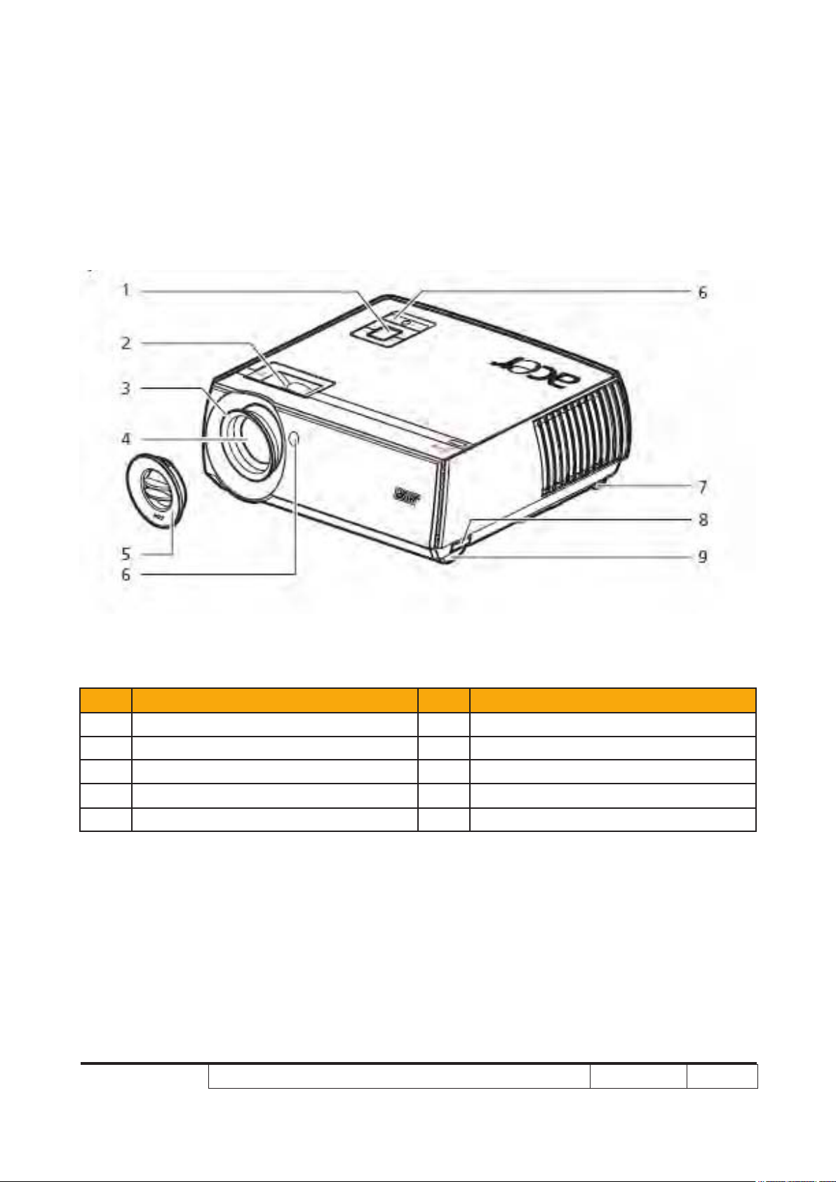
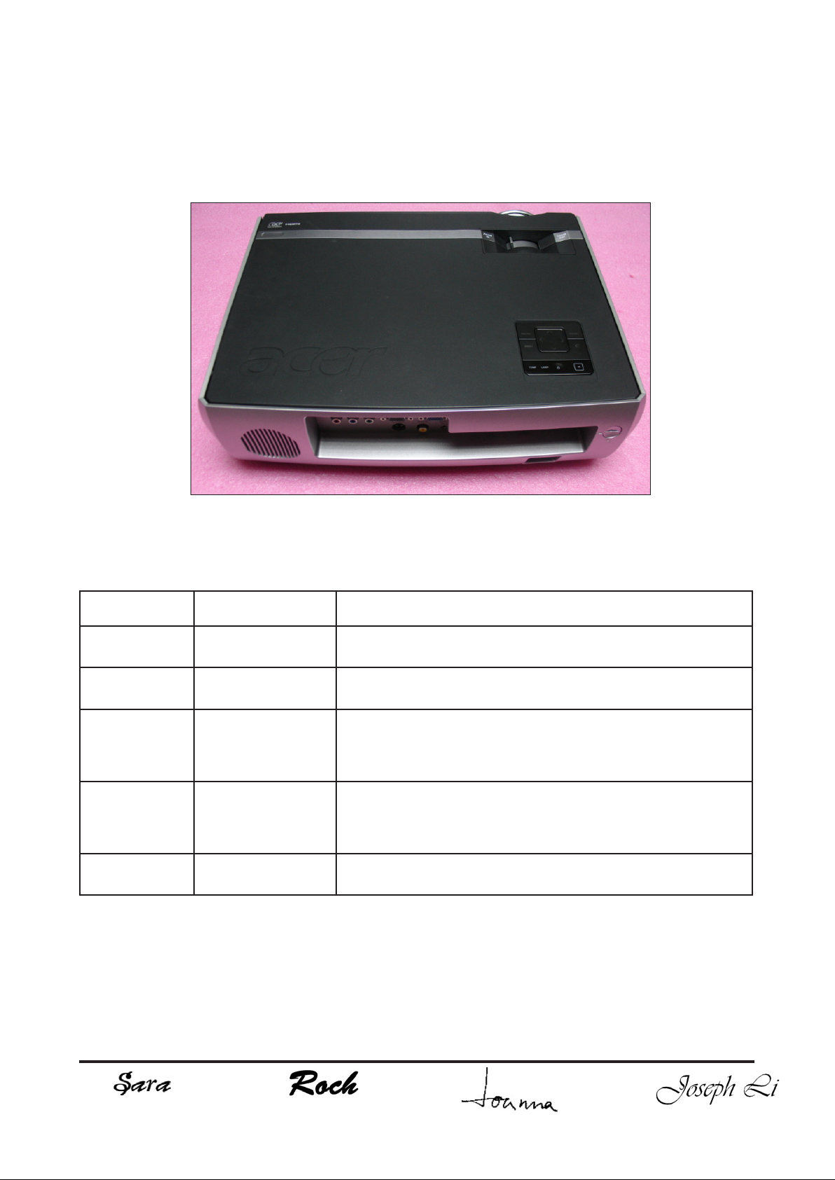
1-3 Product Overview
Projector Outlook
Front /Upper side
Item Description Item Description
1 Control panel 6 Remote control receiver
2 Zoom ring 7 Tilt adjusting wheel
3 Focus ring 8 Elevator button
4 Zoom lens 9 Elevator foot
5 Lens cap
P7280/P7270I/P7280 Refresh/P7270I Refresh/P7290
Condential
1-9
Page 17
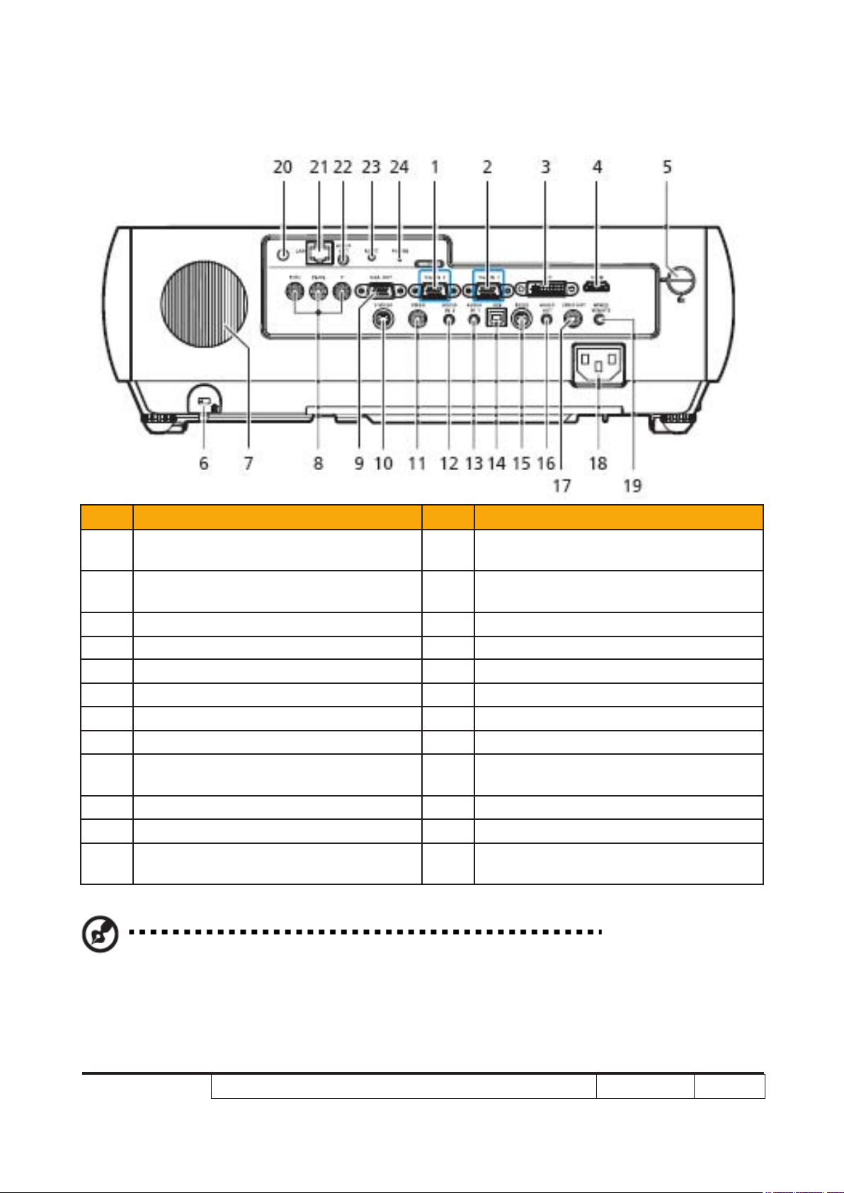
Rear side
Item Description Item Description
1
2
3 DVI input connector (for digit signal) 15 RS232 connector
4 HDMI connector 16 Audio output connector
5 Top cover release button 17 SPDIF output connector
6 KensingtonTM lock port 18 Power socket
7 Horn 19
8 YPbPr/YCbCr input connector 20
9
10 S-Video input connector 22
11 Composite video input connector 23
12
PC analog signal/HDTV/component
video input connector (VGA IN 2)
PC analog signal/HDTV/component
video input connector (VGA IN 1)
Monitor loop-through output
connector (VGA-Out)
Audio input connector (VGA IN 2/
Component/S-video/Composite signal)
13 VGA IN 1/DVID/HDMI with PC signal
14 USB connector
(#)
Wired IR remote input connector
(#)
Antenna
(#)
21
24
Lan (RJ45 Port for 10/100M Ethernet)
(#)
Audio output connector for wireless
(#)
Reset button
(#)
Power LED for wireless
Note: “#” Only for P7270i series.
P7280/P7270I/P7280 Refresh/P7270I Refresh/P7290
Condential
1-10
Page 18
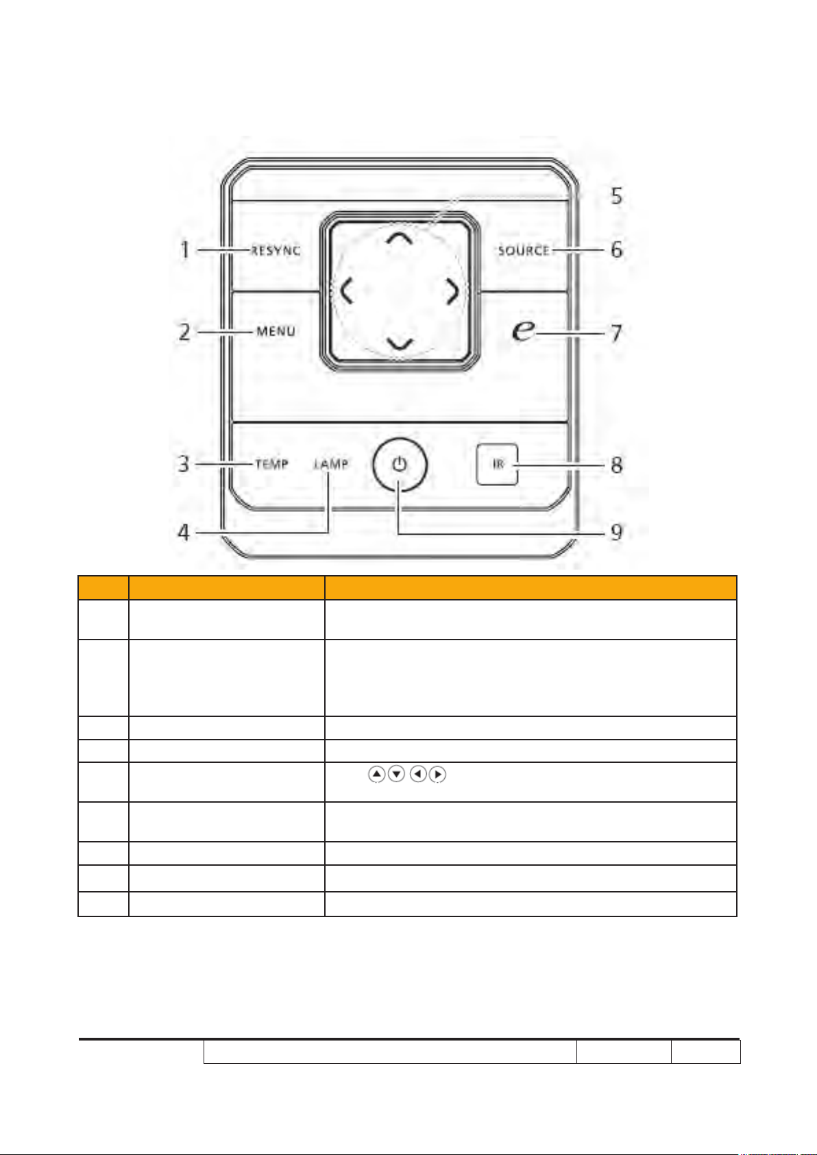
Control Panel
Item Function Description
1 RESYNC
2 MENU
3 TEMP Temp Indicator LED
4 LAMP Lamp Indicator LED
5
6 SOURCE
7 Empowering key Unique Acer functions: eOpening, eView, eTimer. ePower
8 Infrared transmitter Sends signals to the projector.
9 POWER See the contents in “Turning the Projector On Off” section.
Four directional select
keys
Automatically synchronizes the projector to the
input source.
• Press “MENU” to launch the Onscreen display (OSD)
menu, back to the previous step for the OSD menu
operation or exit the OSD menu.
• Conrm your selection of items.
Use to select items or make adjustments to
your selection.
Press “SOURCE” to choose RGB, Component, SVideo,
Composite, DVI, HDTV and HDMI™ sources.
P7280/P7270I/P7280 Refresh/P7270I Refresh/P7290
Condential
1-11
Page 19
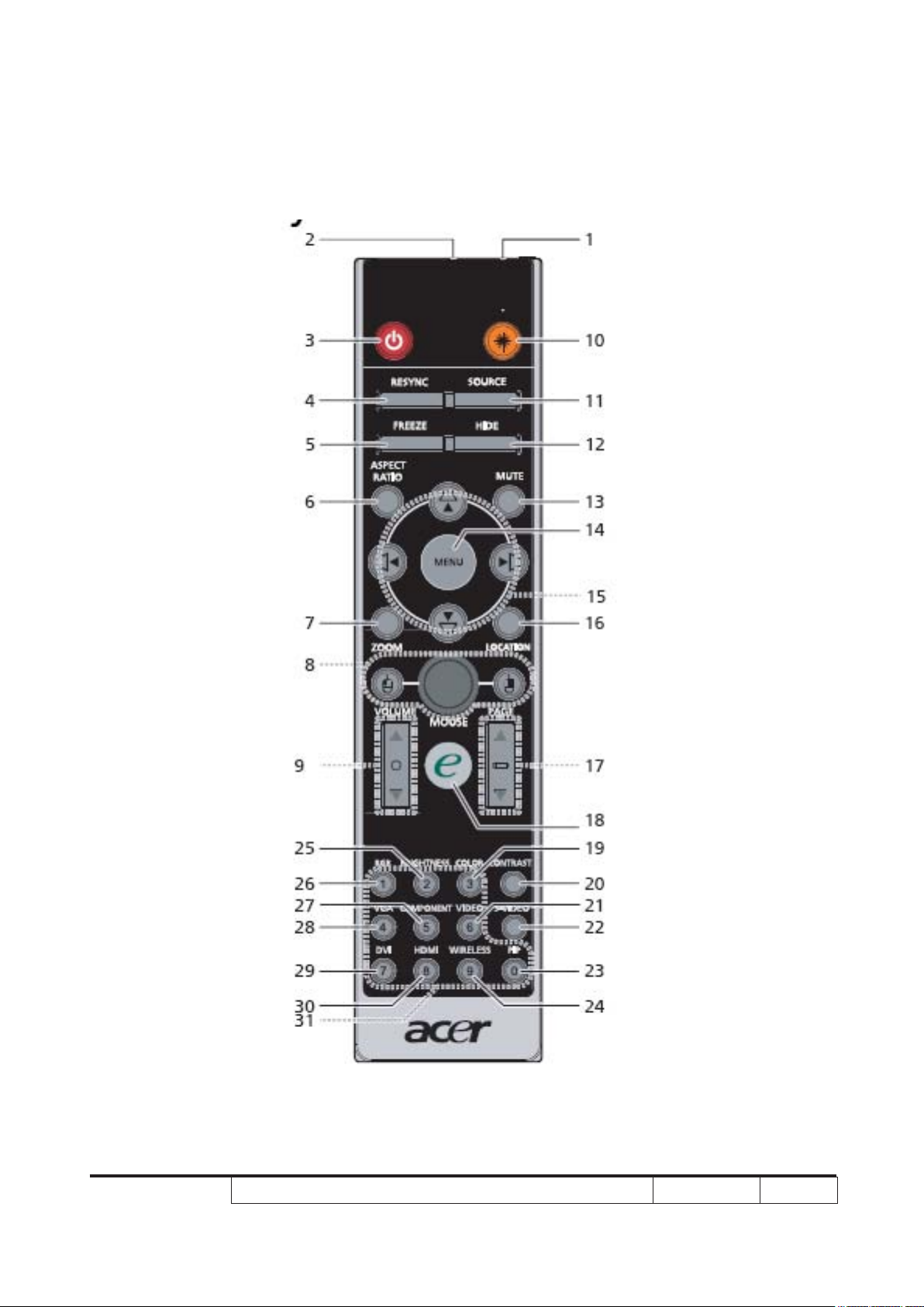
Remote Control Layout
P7280/P7270I/P7280 Refresh/P7270I Refresh/P7290
Condential
1-12
Page 20
Item Icon Function Description
Infrared
transmitter
Sends signals to the projector.
Laser pointer Aim the remote at the viewing screen
2
1
(#)
3 POWER Refer to the “Turning the Projector On/Off” sec
4 RESYNC Automatically synchronizes the projector to the input source.
5 FREEZE To pause the screen image.
6 ASPECT RATIO To choose the desired aspect ratio (Auto/4:3/16:9).
7 ZOOM Zooms the projector display in or out.
Left-/right-click buttons are on the left and right, respectively;
8
MOUSE Left/
Right Click
the center button works as a multidirectional pointer stick. To
enable this function, an USB cable must be connected to
projector from your PC.
9 VOLUME Increases/decreases the volume.
Aim the remote at the viewing screen, press and hold this
(#)
10
Laser button
button to activate the laser pointer.
This function is not supported in Japanese market.
Press “SOURCE” to choose from RGB, Component-p,
11 SOURCE
Component-i, S-Video, Composite, DVI-D, Video and HDTV
sources.
12 HIDE
Momentarily turns off the video. Press “HIDE” to hide the
image, press again to display the image.
13 MUTE To turn on/off the volume.
• Press “MENU” to launch the Onscreen display (OSD) menu,
14 MENU
back to the previous step for the OSD menu operation or
exit the OSD menu.
• Conrm your selection of items.
Four directional
select keys
15
KEYSTONE
Use up, down, left, right buttons to select items or make
adjustments to your selection.
Adjusts the image to compensate for distortion caused by
tilting the projector.
16 LOCATION Choose the menu location on the display screen.
For computer mode only. Use this button to select the next or
17 PAGE
previous page. This function is only available when con-
nected
to a computer via a USB cable.
18
Empowering
key
Unique Acer functions: eOpening, eView, eTimer
Management.
19 COLOR Press “COLOR” to adjust the color temperature of image.
20 CONTRAST
Use the “CONTRAST” option to control the difference
between the lightest and darkest parts of the picture.
21 VIDEO To change source to COMPOSITE VIDEO.
22 S-VIDEO To change source to S-Video.
P7280/P7270I/P7280 Refresh/P7270I Refresh/P7290
Condential
1-13
Page 21
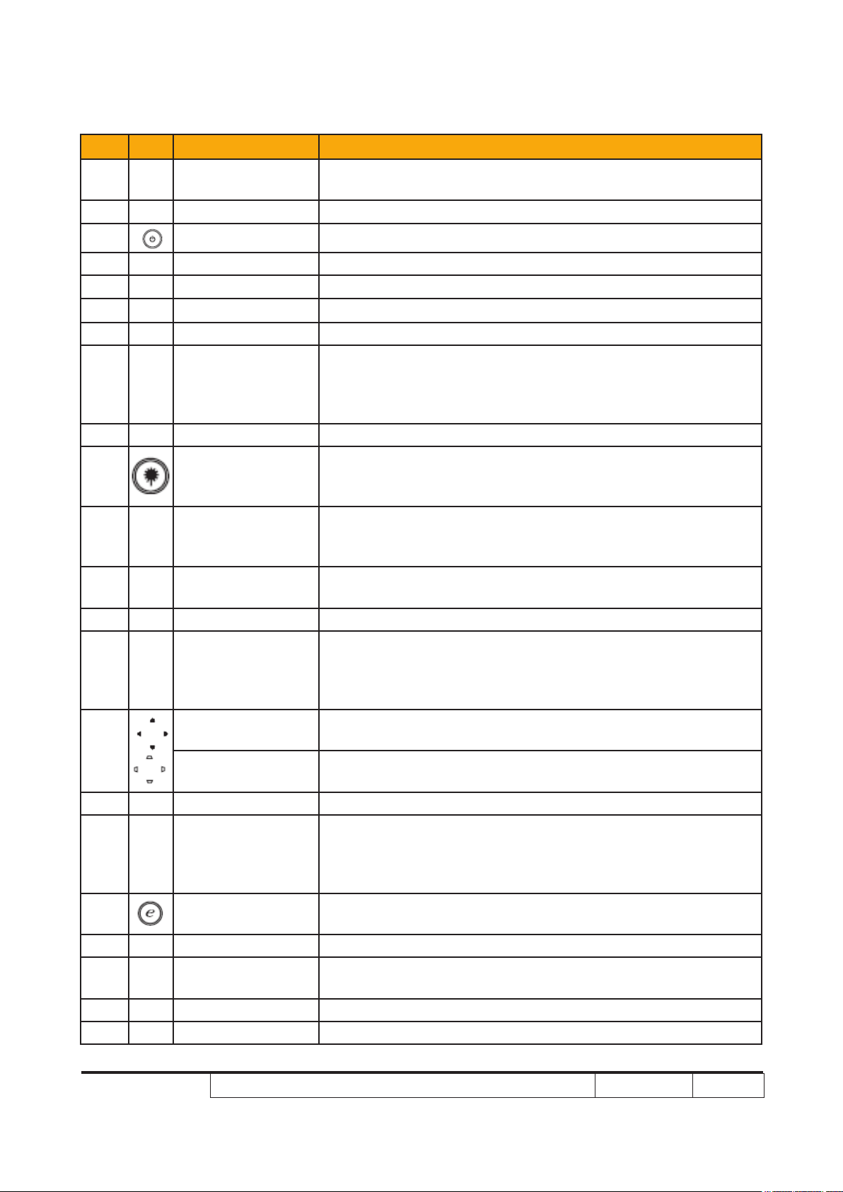
Item Icon Function Description
Press “PIP” to see two screens at the same time. The main
23 PIP
screen projection signal uses VGA input by default while the
smaller PIP display uses a secondary video source.
Press “WIRELESS” to display the image which is wirelessly
24
(*)
WIRELESS
transmitted from the PC to the projector via the “Acer
eProjection Management” utility. (for wireless model)
25 BRIGHTNESS Press “BRIGHTNESS” to adjust the brightness of the image.
26 RGB Press “RGB” for true-color optimization.
Press “COMPONENT” to change source to Component
27 COMPONENT
video.
This connection supports YPbPr (480p/576p/720p/1080i) and
YCbCr (480i/576i).
Press “VGA” to change source to the VGA connector. This
28 VGA
connector supports analog RGB, YPbPr (480p/576p/720p/
1080i), YCbCr (480i/576i) and RGBsync.
Press “DVI” to change source to DVI. This connection sup29 DVI
ports digital RGB, analog RGB, YPbPr (480p/576p/720p/
1080i), YCbCr (480i/576i) and HDCP signals.
30 HDMI™ To change source to HDMI™.
31 KeyPad 0~9 Press “0~9” to input a password in the “Security settings”.
Note: “*” Only for P7270i series.
“#” Japan area is not supported.
P7280/P7270I/P7280 Refresh/P7270I Refresh/P7290
Condential
1-14
Page 22
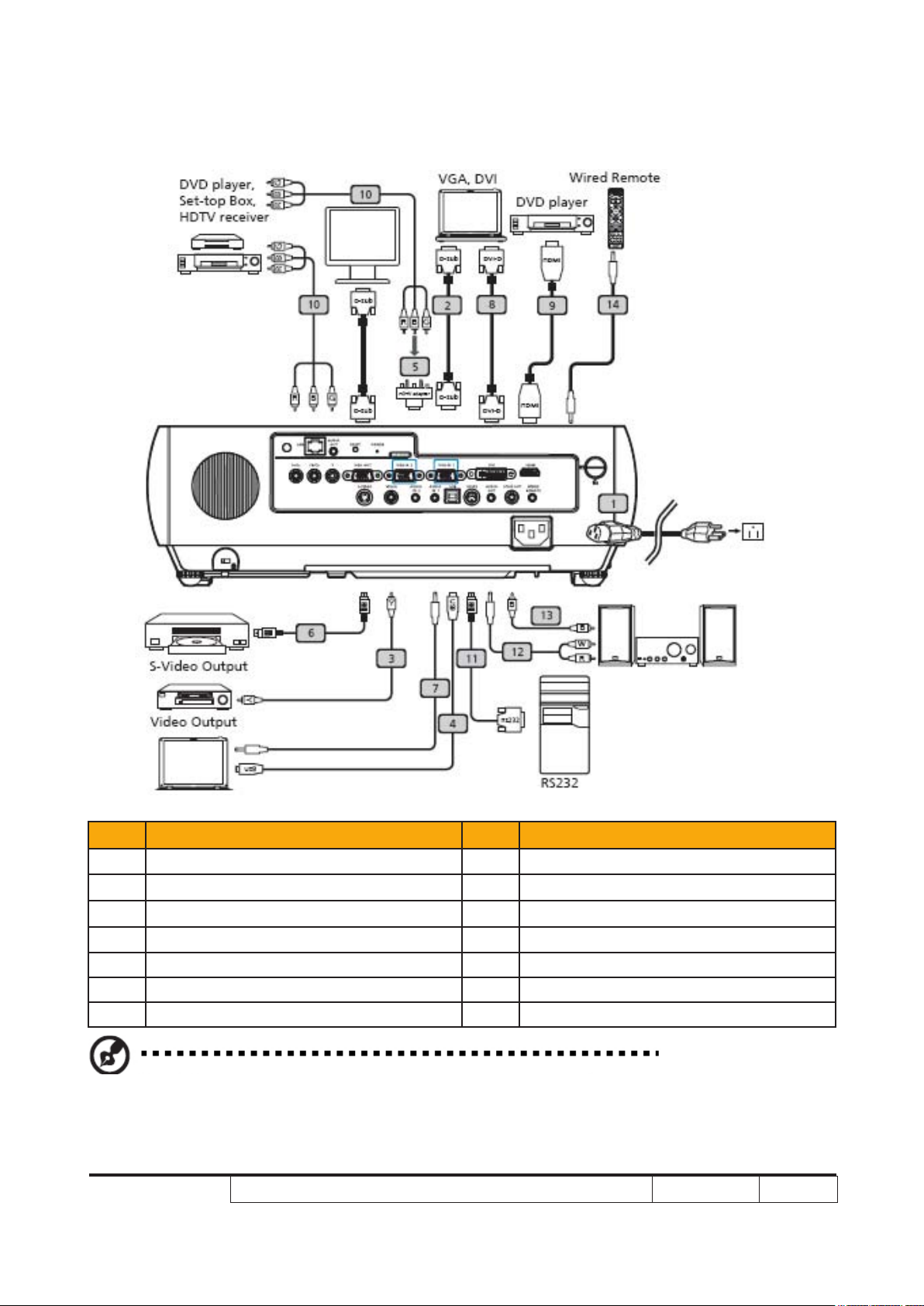
Connecting the Projector
Item Description Item Description
1 Power cord 8 DVI cable
2 VGA cable 9 HDMI cable
3 Composite video cable 10 3 RCA component cable
4 USB cable 11 RS232 cable
5 VGA to component/HDTV adapter 12 Audio cable Jack/RCA
6 S-Video cable 13 SPDIF cable
7 Audio cable jack/jack 14 Audio cable Jack for wired remote
Note: To ensure the projector works well with your computer,please make sure the timing of the
display mode is compatible with the projector.
P7280/P7270I/P7280 Refresh/P7270I Refresh/P7290
Condential
1-15
Page 23
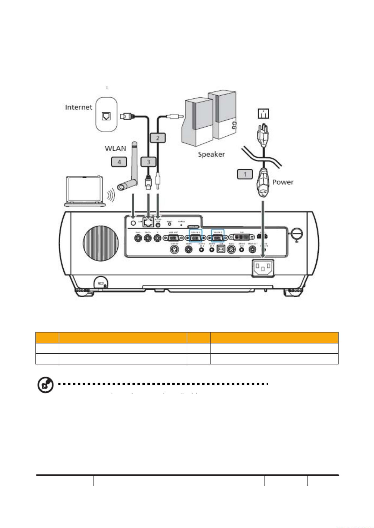
Connecting the Projector for Wireless
Item Description Item Description
1 Power cord 3 Lan cable
2 Audio cable jack 4 Antenna
Note: Only for P7270i
P7280/P7270I/P7280 Refresh/P7270I Refresh/P7290
Condential
1-16
Page 24
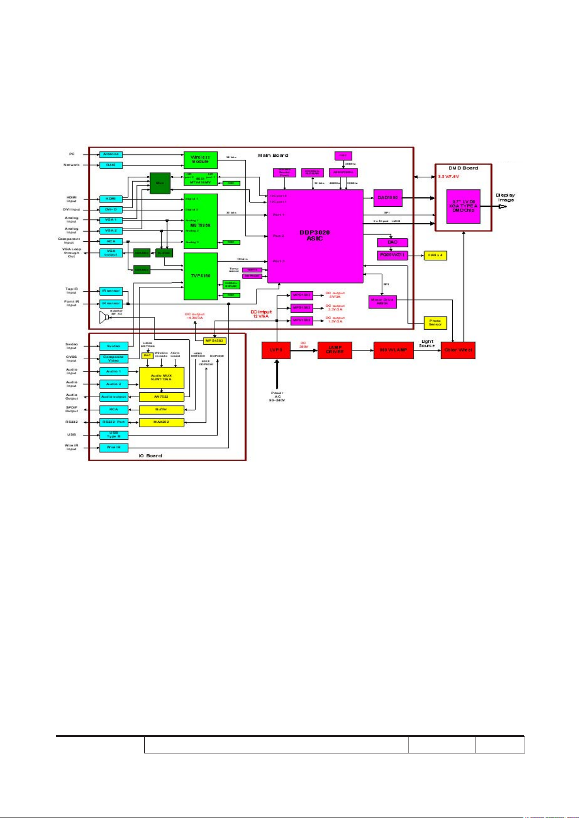
System Block Diagram (for P7270I/P7270I Refresh)
P7280/P7270I/P7280 Refresh/P7270I Refresh/P7290
Condential
1-17
Page 25
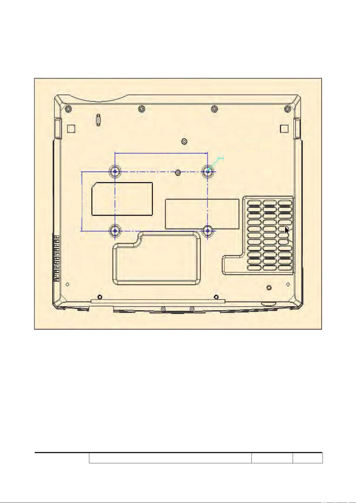
Bottom Cover Dimension
82.30 mm
140.00 mm
M3,DEPTH:8mm
SCALE 1:2
P7280/P7270I/P7280 Refresh/P7270I Refresh/P7290
Condential
1-18
Page 26
Chapter 2
Disassembly & Assembly Process
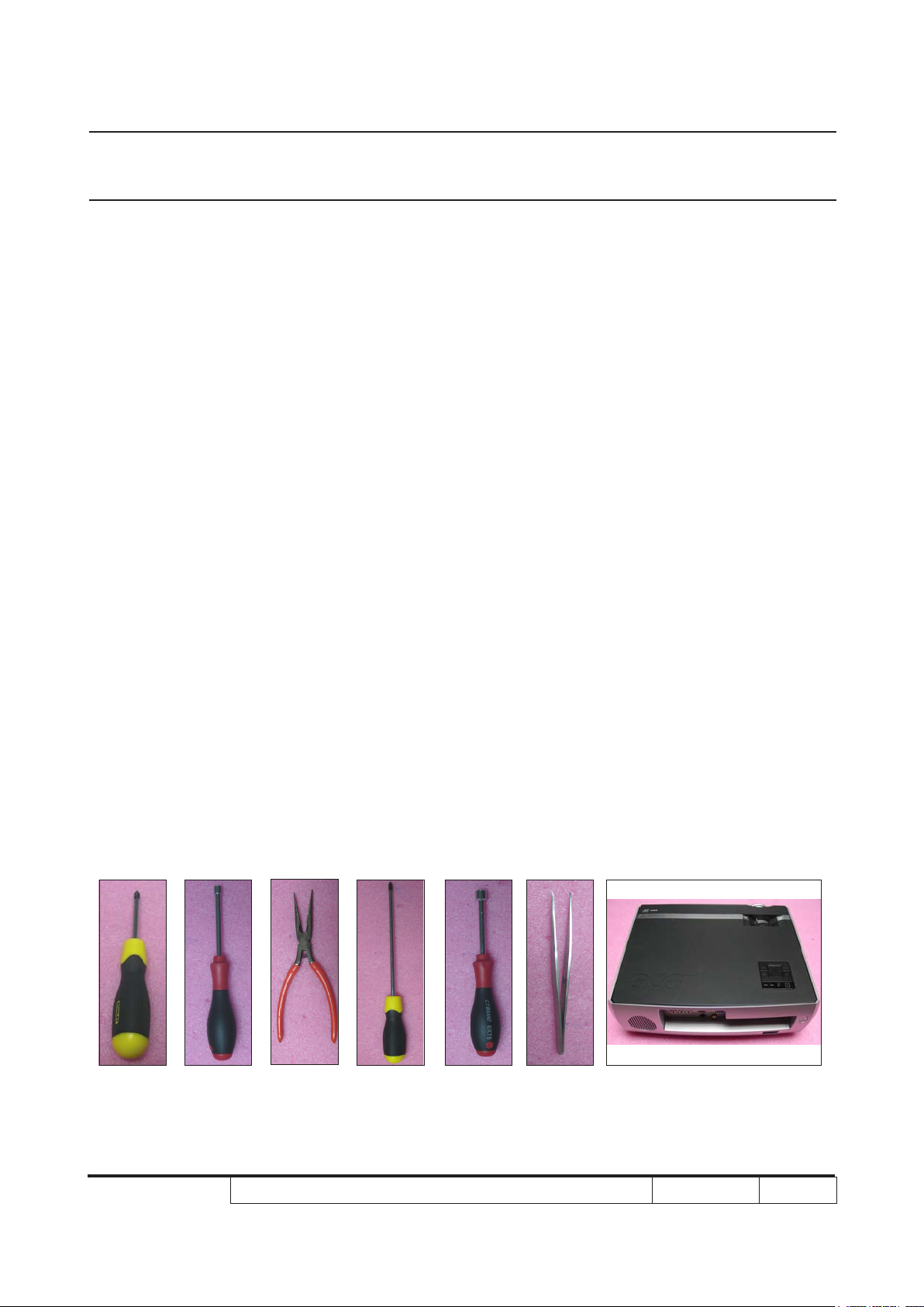
2-1 Equipment Needed & Product Overview
1. Screw Bit (+) :107
2. Hex Sleeves 5mm
3. Long Nose Nipper
4. Screw Bit (+) :102
5. Hex Sleeves 7mm
6. Tweezers
7. Projector
* Before you start: This process is protective level II. Operators should wear electrostatic chains.
* Note: 1. If you need to replace the main board, you have to get into service mode and record the
lamp usage hour. please refer to section 2-27.
2. The disassembly and assembly process for P7280/P7270I/P72780 Refresh/P7270I
Refresh /P7290 is the same. Here, we take P7270i as an example.
P7280/P7270I/P7280 Refresh/P7270I Refresh/P7290
Condential
2-1
Page 27
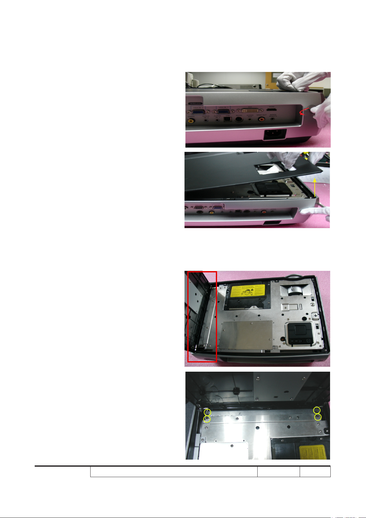
2-2 Disassemble Top Cover
Module
1. Rotate the Top Cover Lock
counterclockwise (as red arrow).
2. Pull up the Top Cover (as yellow arrow).
3. Unscrew 4 screws and disassemble the
Top Cover Module (as yellow circle).
P7280/P7270I/P7280 Refresh/P7270I Refresh/P7290
Condential 2-2
Page 28
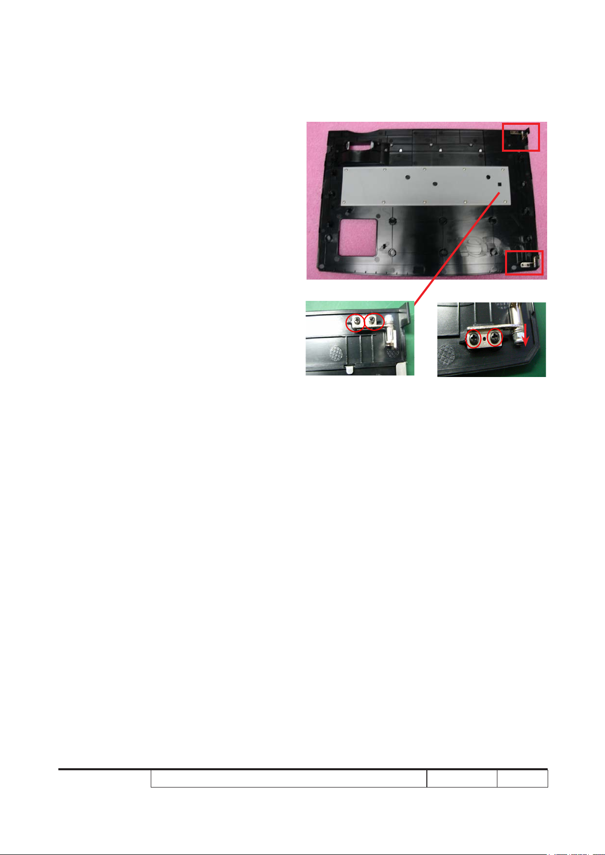
4. Unscrew 2 screws (as red circle) and
disassemble 1 Hinge on each side.
P7280/P7270I/P7280 Refresh/P7270I Refresh/P7290
Condential 2-3
Page 29
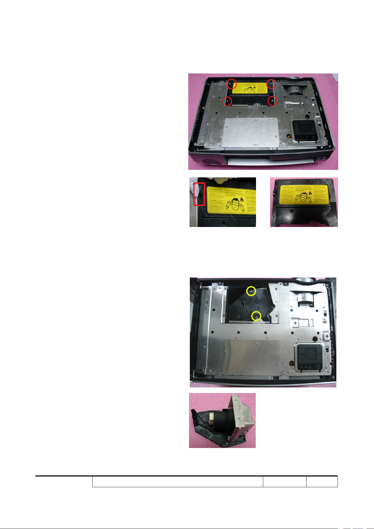
2-3 Disassemble Lamp
Module
1. Unscrew 4 screws (as red circle).
2. Pull up the Lamp Cover from the red
square and disassemble Lamp Cover.
3. Unscrew 2 screws (as yellow circle) and
disassemble Lamp Module.
P7280/P7270I/P7280 Refresh/P7270I Refresh/P7290
Condential 2-4
Page 30
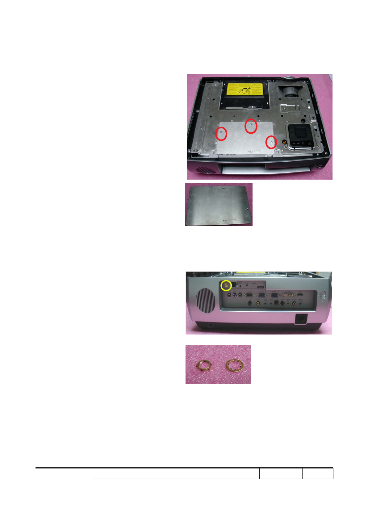
2-4 Disassemble Wireless
Module (only for P7270I
/P7270I Refresh)
1. Unscrew 3 screws (as red circle) and
disassemble Wireless Cover.
2. Unscrew 1 Nut and 1 Washer (as yellow
circle).
P7280/P7270I/P7280 Refresh/P7270I Refresh/P7290
Condential 2-5
Page 31

3. Disassemble the Antenna Cable (as
green square).
4. Unscrew 3 screws (as green circle).
5. Unplug 1 connector (as blue square).
6. Disassemle Wireless Module.
Note : The Antenna Cable must press down
the PCBA and enter from the right of
PCBA , exit from the left of PCBA (as
green arrows).
NOTE: Circuit boards > 10 cm² has been highlighted with the yellow rectangle as
above image shows. Please detach the Circuit boards and follow local
regulations for disposal.
P7280/P7270I/P7280 Refresh/P7270I Refresh/P7290
Condential 2-6
Page 32

2-5 Disassemble Top
Shielding Module
1. Unscrew 10 screws(as red circle).
2. Unscrew 1 screw (as yellow circle).
3. Unplug 1 connector (as red square) and
disassemble the Top Shielding Module.
A
A
P7280/P7270I/P7280 Refresh/P7270I Refresh/P7290
Condential 2-7
Page 33

4. Unplug 1 FPC Cable (as yellow square).
5. Tear off 1 White Mylar (as green square)
and 3 EMI Tapes (as blue square).
P7280/P7270I/P7280 Refresh/P7270I Refresh/P7290
Condential 2-8
Page 34

6. Unscrew 4 screws (as green circle).
7. Disassemble Keypad Module from Top
Shielding Module.
8. Unscrew 6 screws (as blue circle).
9. Disassemble Keypad Board and separate
Keypad Parts.
Menu Key
Aspect key
Keypad Board
Resync Key
Power Key
NOTE: Circuit boards > 10 cm² has been highlighted with the yellow rectangle as
above image shows. Please detach the Circuit boards and follow local
regulations for disposal.
P7280/P7270I/P7280 Refresh/P7270I Refresh/P7290
Condential 2-9
Page 35

2-6 Disassemble Zoom Ring
and Focus Ring
1. Pull up the Zoom Ring (as red arrow) to
disassemble Zoom Ring.
2. Grasp the Focus Ring and rotate 3
tenons counterclockwise to loose 3
tenons for disassemble Focus Ring (as
yellow arrow).
A
A
P7280/P7270I/P7280 Refresh/P7270I Refresh/P7290
Condential 2-10
Page 36

2-7 Disassemble Back Cover
Module
1. Unscrew 2 screws (as red circle).
2. Unscrew 8 hex screws (as yellow circle).
3. Unscrew 3 screws (as green circle).
4. Disassemble the Back Cover Module.
Note: There are 1 tenon on each side when
you disassemble the Back Cover
Module (as red square)
P7280/P7270I/P7280 Refresh/P7270I Refresh/P7290
Condential 2-11
Page 37

2-8 Disassemble Left and
Right Cover Module
1. Unscrew 3 screws on Right Cover (as
red circle).
2. Disassemble the Right Cover Module (as
green arrow) and tear off the Mylar (as
red square).
3. Unscrew 1 screw on Left Cover (as
yellow circle).
4. Disassemble the Left Cover Module (as
yellow arrow).
Note: There are 3 tenons on Left Cover
Module and the same of Right Cover
Module (as green square).
P7280/P7270I/P7280 Refresh/P7270I Refresh/P7290
Condential 2-12
Page 38

2-9 Disassemble Front Cover
Module
1. Turn over the Projector and unscrew 4
screws (as red circle).
2. Unscrew 2 screws (as yellow circle).
3. Cut off Cable Tie (as red square).
4. Unplug 1 connector (as yellow square).
5. Disassemble the Front Cover Module.
6. Remove the Mylar (as green square).
7. Release 2 tenons (as blue square) and
disassemble the IR Sensor.
P7280/P7270I/P7280 Refresh/P7270I Refresh/P7290
Condential 2-13
Page 39

2-10 Disassemble Front
Shielding
1. Unscrew 7 screws (as red circle).
2. Disassemble the Front Shielding.
A
A
B
C
B
C
P7280/P7270I/P7280 Refresh/P7270I Refresh/P7290
Condential 2-14
Page 40

2-11 Disassemble Main Board
Module and I/O Board
Module
1. Unscrew 4 screws (as red circle).
2. Unplug 11 connectors (as yellow square).
Note: Add 1 connector (as orange square)
(only for P7280/P7280 Refresh/P7290)
3. Disassemble Main Board Module and I/O
Board Module.
A
Only for P7280/P7280 Refresh/P7290 (Blower Cable)
4. Tear off Mylar (as blue square) from I/O
Board.
5. Unscrew 2 screws (as yellow circle ) and
turn over Main Board then unscrew 1
screw (as green circle).
A
P7280/P7270I/P7280 Refresh/P7270I Refresh/P7290
Condential 2-15
Page 41

6. Unplug 2 connectors (as green square).
7. Disassemble I/O Board Module from Main
Board Module.
8. Unscrew 2 Copper Holders (as green
circle).
9. Unscrew 3 Copper Holders (as blue circle).
NOTE: Circuit boards > 10 cm² has been highlighted with the yellow rectangle as
above image shows. Please detach the Circuit boards and follow local
regulations for disposal.
P7280/P7270I/P7280 Refresh/P7270I Refresh/P7290
Condential 2-16
Page 42

2-12 Disassemble Shielding
Module
1. Unscrew 5 screws (as red circle).
2. Loose Interlock Switch (as red square).
3. Disassemble Shielding Module .First
Left side, then Right side.
B
A
P7280/P7270I/P7280 Refresh/P7270I Refresh/P7290
Condential 2-17
Page 43

4. Unscrew 4 screws (as yellow circle) and
disassemble 2 Speakers.
5. Tear off the Mylar (as green square)
6. Disassemble 1 Spring (as yellow square)
7. Unscrew 3 screws (as green circle)
8. Disassemble Iron Sheet from the
Shielding Module.
B
A
P7280/P7270I/P7280 Refresh/P7270I Refresh/P7290
Condential 2-18
Page 44

2-13 Disassemble LVPS
Module
1. Unscrew 2 screws to disassemble the
Blower (as red circle / only for P7280/
P7280 Refresh/P7290).
2. Tear off the Mylar (as red square).
3. Unscrew 1 ground screw (as yellow circle).
4. Unscrew 5 screws(as green circle).
5. Disassemble LVPS Shielding.
P7280/P7270I/P7280 Refresh/P7270I Refresh/P7290
Condential 2-19
Page 45

6. Unplug 3 connectors (as green square)
(only for P7270I/P7270I Refresh)
7. Tear off Mylar and disassemble P7270I/
P7270I Refresh LVPS Module.
8. Unplug 2 connectors (as blue square)
(only for P7280/P7280 Refresh/P7290)
9. Tear off Mylar and disassemble P7280/
P7280 Refresh/P7290 LVPS Module.
P7270I/P7270I Refresh
P7280/P7280 Refresh/P7290
NOTE: Circuit boards > 10 cm² has been highlighted with the yellow rectangle as
above image shows. Please detach the Circuit boards and follow local
regulations for disposal.
P7280/P7270I/P7280 Refresh/P7270I Refresh/P7290
Condential 2-20
Page 46

2-14 Disassemble Fan
Module
1. Unscrew 2 screws (as red circle).
2. Disassemble Fan Module.
P7280/P7270I/P7280 Refresh/P7270I Refresh/P7290
Condential 2-21
Page 47

2-15 Disassemble Engine
Module
1. Unscrew 4 screws (as yellow circle).
E
C
2. Unscrew 4 screws (as green circle).
A
D
B
A
B
C
E
P7280/P7270I/P7280 Refresh/P7270I Refresh/P7290
D
Condential 2-22
Page 48

3. Disassemble the Engine Module.
4. Tear off the Mylar (as red square).
5. Unscrew 1 screw (as red circle) and
disassemble the Thermal Switch.
P7280/P7270I/P7280 Refresh/P7270I Refresh/P7290
Condential 2-23
Page 49

2-16 Disassemble Color
Wheel Module
1. Unscrew 2 screws (as yellow circle).
2. Disassemble the Color Wheel Module.
3. Unscrew 1 screw (as green circle).
4. Disassemble the Photo Sensor Board.
P7280/P7270I/P7280 Refresh/P7270I Refresh/P7290
Condential 2-24
Page 50

2-17 Disassemble DMD
Board and DMD Chip
1. Unscrew 4 screws (as blue circle).
2. Disassemble Heat Sink.
3. Unscrew 4 hex screws (as orange circle).
4. Disassemble DMD Board and DMD Chip.
5. Unscrew 1 screw (as green square).
6. Disassemble the Iron from DMD Board.
NOTE: Circuit boards > 10 cm² has been
highlighted with the yellow rectangle
as above image shows. Please
detach the Circuit boards and follow
local regulations for disposal.
P7280/P7270I/P7280 Refresh/P7270I Refresh/P7290
Condential 2-25
Page 51

2-18 Disassemble Lamp
Blower Module
1. Unscrew 2 screws (as red circle).
2. Disassemble Lamp Blower Module and
separate the Blower from the Rubber.
Note: Avoid to press the Blower with great
strength.
P7280/P7270I/P7280 Refresh/P7270I Refresh/P7290
Condential 2-26
Page 52

2-19 Disassemble ROD
Blower Module
1. Unscrew 2 screws (as yellow circle).
2. Disassemble ROD Blower Module and
separate the Blower from the Rubber.
Note: Avoid to press the Blower with great
strength.
P7280/P7270I/P7280 Refresh/P7270I Refresh/P7290
Condential 2-27
Page 53

2-20 Disassemble ROD Duct
1. Unscrew 1 screw (as red circle).
2. Disassemble the ROD Duct.
P7280/P7270I/P7280 Refresh/P7270I Refresh/P7290
Condential 2-28
Page 54

2-21 Disassemble System
Duct Module
1. Unscrew 2 screws (as yellow circle) to
loose the Lamp Cable.
2. Unscrew 1 screw (as green circle) from
the Bottom Cover.
3. Disassemble System Duct Module.
4. Unscrew 3 screws (as blue circle).
5. Disassemble System Duct Top and
Bottom Cover.
P7280/P7270I/P7280 Refresh/P7270I Refresh/P7290
Condential 2-29
Page 55

2-22 Disassemble Lamp
Driver Module
1. Unscrew 4 screws (as red circle)
(only for P7270I/P7270I Refresh).
2. Disassemble P7270I/P7270I Refresh
Lamp Driver Module.
3. Unscrew 3 screws (as yellow circle)
(only for P7280/P7280 Refresh/P7290).
4. Disassemble P7280 /P7280 Refresh/
P7290 Lamp Driver Module and tear off
the Mylar (as red square).
P7270I/P7270I Refresh
P7280/P7280 Refresh/P7290
NOTE: Circuit boards > 10 cm² has been highlighted with the yellow rectangle as
above image shows. Please detach the Circuit boards and follow local
regulations for disposal.
P7280/P7270I/P7280 Refresh/P7270I Refresh/P7290
Condential 2-30
Page 56

2-23 Disassemble Lamp
Driver Holder (only for
P7270I/P7270I Refresh)
1. Unscrew 2 screws (as green circle).
2. Disassemble Lamp Driver Holder.
Note: There is 1 Plastic Holder for P7280/P7280
Refresh/P7290 (as red square).
P7270I/P7270I Refresh
P7280/P7280 Refresh/P7290
P7280/P7270I/P7280 Refresh/P7270I Refresh/P7290
Condential 2-31
Page 57

2-24 Disassemble Interrupt
Switch Module
1. Unscrew 1 screw (as red circle) and
disassemble 1 Interrupt Switch Module on
each side.
2. Use Tweezers to loose 2 tenons (as yellow
circle) and disassemble the Interrupt
Switch from the Holder.
P7280/P7270I/P7280 Refresh/P7270I Refresh/P7290
Condential 2-32
Page 58

2-25 Disassemble Elevator
Module
1. Unscrew 3 screws (as red circle) and
disassemble 1 Spring (as red square) on
each side.
2. Disassemble Elevator Module.
3. Loose 2 tenons (as yellow circle).
4. Separate Holder and Elevator Key.
5. Disassemble Foot Rubber on Elevator
Foot.
P7280/P7270I/P7280 Refresh/P7270I Refresh/P7290
Condential 2-33
Page 59

2-26 Rod Adjustment
1. Environment adjustment
- The distance between the engine and
the screen is 1.91M.
- This process should be done at a dark
environment. (under 5 Lux)
2. Procedure adjustment
- Change the screen to “white screen.”
- Adjust the screws by using the rod on
the engine module to readjust the image.
(adjust until the yellowish or bluish parts
disappeared.)
3. Abnormal image inspection
Screw 2
- It should not have any abnormal color
at the rim of the image by estimating
through the eyes.
Note: - To avoid over adjusting the rod.
- “Screw 1” should be adjusted rst, and
then adjust the “Screw 2”. After the
adjustment, use the glue to x the screws.
Screw 1
P7280/P7270I/P7280 Refresh/P7270I Refresh/P7290
Condential 2-34
Page 60

2-27 Re-write Lamp Usage
Hour
- Take P7280 for example, P7270I/P7270I
Refresh is the same as P7280/P7280 Refresh/
P7290.
1. Get into service mode
- Press (power→left→left→menu) to get
into service mode.
2. Use left or right key to re-write the lamp
hour back to previous lamp usage hour.
3. Choose exit
Note: left key = decrease lamp hour
right key =increase lamp hour
Re-write lamp
usage hour
P7280/P7270I/P7280 Refresh/P7270I Refresh/P7290
Condential 2-35
Page 61

2-28 Assemble Elevator
Module
1. Assemble Foot Rubber on Elevator Foot,
fasten 2 tenons (as green circle) to
assemble Holder and Elevator Key.
2. Assemble Elevator Module.
3. Assemble 1 spring (as red square) and 3
screws on each side (as red circle).
Note: The Elevator KEY installed in the direction
(inward side of the ramp) (as yellow square)
P7280/P7270I/P7280 Refresh/P7270I Refresh/P7290
Condential 2-36
Page 62

2-29 Assemble Interrupt
Switch Module
Holder
1. Fasten 2 tennons (as yellow circle) and
assemble the Interrupt Switch on the
Holder.
2. Assemble 1 Interrupt Switch and screw 1
screw (as red circle) on each side
2-30 Assemble Lamp Driver
Interrupt Switch
Holder (only for P7270I/
P7270I Refresh)
1. Assemble the Lamp Driver Holder and
screw 2 screws (as green circle)
P7270I/P7270I Refresh
P7280/P7270I/P7280 Refresh/P7270I Refresh/P7290
Condential 2-37
Page 63

2-31 Assemble Lamp Driver
Module
1. Assemble P7270I/P7270I Refresh Lamp
Driver Module and screw 4 screws (as
red circle).
2. Paste Mylar and assemble P7280/P7280
Refresh/P7290 Lamp Driver Module and
screw 3 screws (as yellow circle)
Note: 1. The Mylar holes must consistent with
Lamp Driver PCBA Holes when soak
Mylar (as yellow arrow)
2. 2P and 5P Wires’s position when
assemble 2P and 5P Wires
(as red and yellow square)
P7270I/P7270I Refresh
2P Wire
5P Wire
P7270I/P7270I Refresh
P7280/P7280 Refresh/P7290
P7280/P7270I/P7280 Refresh/P7270I Refresh/P7290
5P Wire
2P Wire
P7280/P7280 Refresh/P7290
Condential 2-38
Page 64

2-32 Assemble System Duct
Module
1. Assemble System Duct Top and Bottom
Cover and screw 3 screws (as blue circle).
2. Assemble System Duct Module on Bottom
Cover and screw 1 screw (as green circle).
3. Assemble Lamp Cable and screw 2 screws
(as yellow circle).
P7280/P7270I/P7280 Refresh/P7270I Refresh/P7290
Condential 2-39
Page 65

2-33 Assemble ROD Duct
1. Assemble the ROD Duct and screw 1
screw (as red circle).
2-34 Assemble ROD Blower
Module
1. Assemble ROD Blower on the Rubber.
2. Screw 2 screws (as yellow circle).
Note: Avoid to press the Blower with great
strength.
P7280/P7270I/P7280 Refresh/P7270I Refresh/P7290
Condential 2-40
Page 66

2-35 Assemble Lamp Blower
Module
1. Assemble Lamp Blower on the Rubber.
2. Screw 2 screws (as red circle).
Note: Avoid to press the Blower with great
strength.
2-36 Assemble DMD Board
and DMD Chip
1. Assemble the Iron on DMD Board and
screw 1 screw (as yellow square)
2. Assemble the DMD Board and DMD Chip
and other parts and screw 4 screws
(as orange circle)
3. Assemble Heat Sink and screw 4 screws
(as blue circle)
P7280/P7270I/P7280 Refresh/P7270I Refresh/P7290
Condential 2-41
Page 67

2-37 Assemble Color Wheel
Module
1. Assemble Photo Sensor Board and screw
1 screw (as green circle).
2. Assemble Color Wheel Module and screw
2 screws (as yellow circle).
2-38 Assemble Thermal
Switch
1. Assemble Thermal Switch and screw 1
screw (as red circle).
P7280/P7270I/P7280 Refresh/P7270I Refresh/P7290
Condential 2-42
Page 68

2-39 Assemble Engine
Module
1. Paste the Mylar (as red square).
2. Assemble the Engine Module.
3. Screw 4 screws (as red circle).
4. Screw 4 screws (as yellow circle).
A
A
B
D
C
E
B
C
P7280/P7270I/P7280 Refresh/P7270I Refresh/P7290
D
E
Condential 2-43
Page 69

2-40 Assemble Fan Module
1. Assemble the Fan Module and screw 2
screws (as red circle).
P7280/P7270I/P7280 Refresh/P7270I Refresh/P7290
Condential 2-44
Page 70

2-41 Assemble LVPS Module
1. Paste Mylar and assemble P7270I/P7270I
Refresh LVPS Module.
2. Insert 3 connectors (as yellow square/only
for P7270I/P7270I Refresh).
3. Paste Mylar and assemble P7280/P7280
Refresh/P7290 LVPS Module.
4. Insert 2 connectors (as blue square/ only
for P7280/P7280 Refresh/P7290).
P7270I/P7270I Refresh
P7280/P7280 Refresh/P7290
P7280/P7270I/P7280 Refresh/P7270I Refresh/P7290
Condential 2-45
Page 71

5. Assemble LVPS Shielding and screw 5
screws (as green circle) and 1 ground
screw (as yellow circle).
6. Paste Mylar (as red square) and assemble
LVPS Fan and screw 2 screws (as red
circle / only for P7280/P7280 Refresh/
P7290)
Note: The 16P Wire must be come out from the
middle of Two Holders (as yellow square).
16P Wire
P7280/P7270I/P7280 Refresh/P7270I Refresh/P7290
Condential 2-46
Page 72

2-42 Assemble Shielding
Module
1. Assemble Iron Sheet on the Shielding
Module and screw 3 screws (as green
circle).
2. Assemble 1 Spring (as yellow square).
3. Paste 1 Mylar (as green square).
4. Assemble 1 Speaker and screw 2 screws
on each side (as yellow circle).
A
B
B
A
P7280/P7270I/P7280 Refresh/P7270I Refresh/P7290
Condential 2-47
Page 73

5. Assemble Interlock Switch (as red square)
and the Shielding Module.
6. Screw 5 screws (as red circle) on Left and
Right side.
P7280/P7270I/P7280 Refresh/P7270I Refresh/P7290
Condential 2-48
Page 74

2-43 Assemble Main Board
Module and I/O Board
Module
1. Screw 3 Copper Holders (as blue circle)
on Main Board.
2. Screw 2 Copper Holders (as green circle)
on I/O Board.
3. Insert 2 connectors (as green square)
and assemble I/O Board Module on Main
Board Module.
P7280/P7270I/P7280 Refresh/P7270I Refresh/P7290
Condential 2-49
Page 75

4. Screw 3 screws (as yellow circle) and
paste Mylar (as blue square).
5. Assemble Main Board Module.
6. Insert 11 connectors (as yellow square)
and screw 4 screws (as red circle).
Note: Add 1 connector (as orange square)
(only for P7280/P7280 Refresh/P7290).
A
Only for P7280/P7280 Refresh/P7290 (Blower Cable)
P7280/P7270I/P7280 Refresh/P7270I Refresh/P7290
A
Condential 2-50
Page 76

2-44 Assemble Front
Shielding
1. Assemble the Front Shielding.
2. Screw 7 screws (as red circle).
C
A
A
P7280/P7270I/P7280 Refresh/P7270I Refresh/P7290
B
B
C
Condential 2-51
Page 77

2-45 Assemble Front Cover
Module
Mylar
1. Assemble the IR Sensor and paste the
Mylar (as green square).
2. Insert 1 connector (as yellow square) and
bundle up Cable Tie (as red square).
3. Screw 2 screws (as yellow circle) and
turn over the Projector.
4. Screw 4 screws (as red circle).
IR Sensor
P7280/P7270I/P7280 Refresh/P7270I Refresh/P7290
Condential 2-52
Page 78

2-46 Assemble Left and Right
Cover Module
1. Assemble the Left Cover Module (as
yellow arrow) and screw 1 screw
(as yellow circle).
2. Paste the Mylar (as red square)
3. Assemble the Right cover Module (as
green arrow) and screw 3 screws (as red
circle).
Note: There are 3 tenons on Left Cover Module
and the same of the Right Cover Module
(as green square)
P7280/P7270I/P7280 Refresh/P7270I Refresh/P7290
Condential 2-53
Page 79

2-47 Assemble Back Cover
Module
1. Assemble the Back Cover.
2. Screw 3 screws (as green circle).
Note: There are 1 tenons on each side when
you assemble the Back Cover (as red
square)
P7280/P7270I/P7280 Refresh/P7270I Refresh/P7290
Condential 2-54
Page 80

3. Screw 8 hex screws (as yellow circle).
4. Screw 2 screws (as red circle).
2-48 Assemble Zoom Ring
and Focus Ring
1. Grasp the Focus Ring and rotate 3 tenons
clockwise to fasten 3 tenons for assemble
Focus Ring (as yellow arrow).
2. Press the Zoom Ring (as red arrow).
P7280/P7270I/P7280 Refresh/P7270I Refresh/P7290
Condential 2-55
Page 81

2-49 Assemble Top Shielding
Module
Menu Key
1. Assemble Keypad Board and Keypad
Parts.
2. Screw 6 screws (as blue circle).
3. Assemble Keypad Module on the Top
Shielding Module.
4. Screw 4 screws (as green circle).
Keypad Board
Aspect key
Power Key
Resync Key
P7280/P7270I/P7280 Refresh/P7270I Refresh/P7290
Condential 2-56
Page 82

5. Paste 1 White Mylar (as green square)
and 3 EMI Tapes (as blue square).
6. Insert 1 FPC Cable (as yellow square).
7. Insert 1 connector (as red square) and
assemble the Top Shielding Module.
8. Screw 10 screws (as red circle).
9. Screw 1 screw (as yellow circle).
P7280/P7270I/P7280 Refresh/P7270I Refresh/P7290
Condential 2-57
Page 83

2-50 Assemble Wireless
Module (only for P7270I/
P7270I Refresh)
1. Insert 1 connector (as yellow square).
2. Screw 3 screws (as green circle).
3. Assemble the Antenna Cable (as green
square) and screw 1 Washer and 1 Nut
(as yellow circle).
P7280/P7270I/P7280 Refresh/P7270I Refresh/P7290
Condential 2-58
Page 84

4. Assemble Wireless Cover and screw 3
screws (as red circle).
Note: The Antenna Cable must press down the
PCBA and enter from the right of PCBA ,
exit from the left of PCBA (as yellow arrow)
P7280/P7270I/P7280 Refresh/P7270I Refresh/P7290
Condential 2-59
Page 85

2-51 Assemble Lamp Module
1. Assemble Lamp Module and screw 2
screws (as yellow circle).
2. Assemble the Lamp Cover and screw 4
screws (as red circle).
P7280/P7270I/P7280 Refresh/P7270I Refresh/P7290
Condential 2-60
Page 86

2-52 Assemble Top Cover
Module
1. Assemble 1 Hinge and screw 2 screws
(as red circle) on each side.
P7280/P7270I/P7280 Refresh/P7270I Refresh/P7290
Condential 2-61
Page 87

. Assemble the Top Cover and screw 4
2
screws (as yellow circle).
3. Push down the Front Cover and the
assembly completed.
P7280/P7270I/P7280 Refresh/P7270I Refresh/P7290
Condential 2-62
Page 88

Chapter 3
Troubleshooting
3-1 LED Lighting Message
Lamp LED Temp LED Power LED
Message
Red Red Red Blue
Standby
(power cord plugged in)
Power button ON X X X V
Lamp retry X X X
Turning off (cooling state) X X
Turning off (cooling completed) X X V X
Error (thermal failure) X V X V
Error (fan failure) X
X X V X
Quick
ashing
Quick
ashing
Quick
ashing
X V
X
Error (lamp failure) V X X V
Error (color Wheel failure)
Note: "
Steady light, "
V" →
X" →→
P7280/P7270I/P7280 Refresh/P7270I Refresh/P7290 Condential
No light
Quick
ashing
X X V
3-1
Page 89

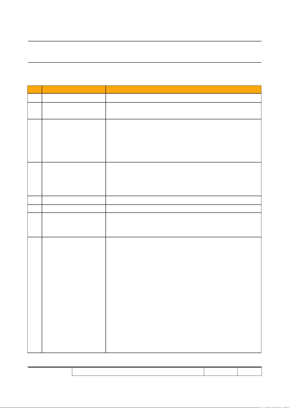
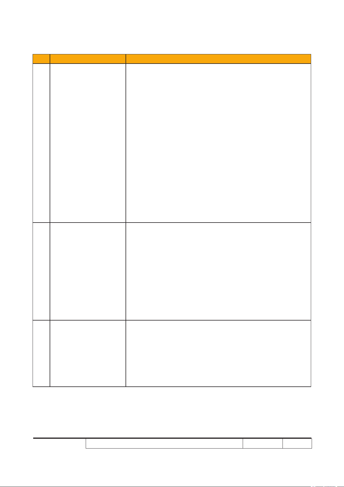
3-2 Main Procedure
No Symptom Procedure
- Ensure the Power Cord and AC Power Outlet are securely con-
nected
- Ensure all connectors are securely connected and aren’t broken
1 No Power
- Check Lamp Driver
- Check LVPS
- Check Main Board
- Check LED Status
a. Thermal/Fan Failure: Temp LED (lights red or ashes red),
Power LED (lights blue)
- Check Thermal Switch
- Check Fan
- Check Main Board
2 Auto Shut Down
3 No Light On
b. Lamp Failure: Lamp LED (lights red), Power LED (lights blue)
- Check Lamp
- Check Lamp Driver
- Check Main Board
c. Color Wheel Failure: Lamp LED (quick ashing red), Power
LED (lights blue)
- Check Color Wheel
- Check Photo Senor
- Check Main Board
- Ensure all connectors are securely connected and aren’t broken
- Check Lamp cover
- Check Interrupt Switch
- Check Lamp Module
- Check Lamp Driver
- Check LVPS
- Check Main Board
- Check Color Wheel
- Check Photo Sensor Board
P7280/P7270I/P7280 Refresh/P7270I Refresh/P7290 Condential
3-2
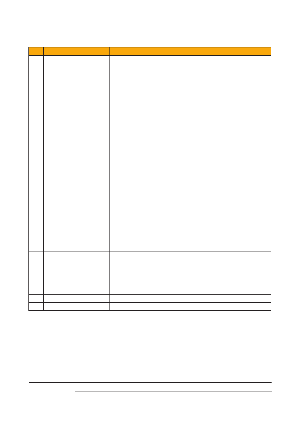
Page 90

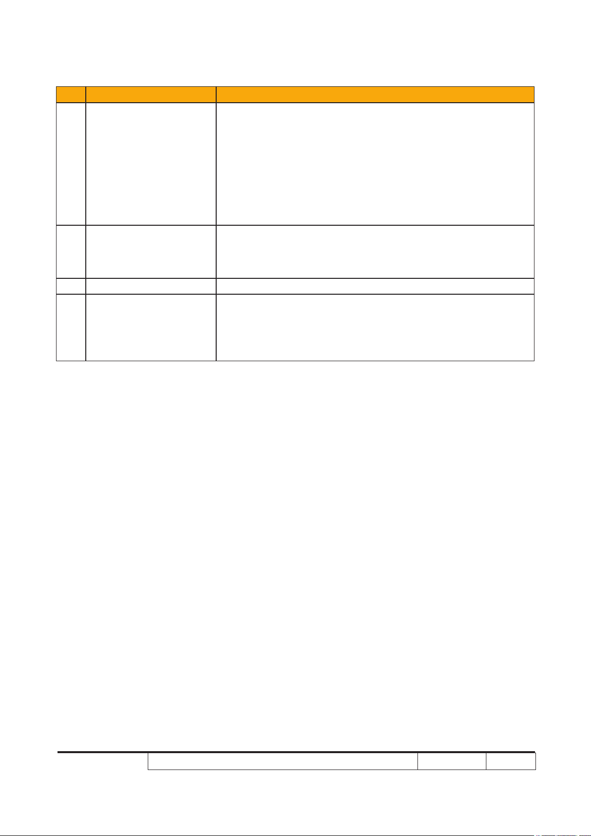
No Symptom Procedure
- Ensure the Signal Cable and Source work
(If you connect multiple sources at the same time, use the
“Source” button switch)
- Ensure all connectors are securely connected and aren’t
broken
- Check Main Board
4 No Image
5 Mechanical Noise
6 Line Bar/Line Defect
- Check DMD Board
- Check I/O Board
- Check DMD Chip
- Check Engine Module
- Check Wireless Module and IP address (If you use WLAN or
LAN to transfer signal)
- Check Color Wheel
- Check Fan Module
- Check if the Main Board and the DMD Board are
assembled properly
- Check Main Board
- Check DMD Board
- Check DMD Chip
- Do “Reset (All data)” of the OSD Menu
7 Image Flicker
8 Color Abnormal
P7280/P7270I/P7280 Refresh/P7270I Refresh/P7290 Condential
- Ensure that the signal cables and source are work as well
- Check Lamp Module
- Check Color Wheel
- Check Photo Sensor and clean Photo Sensor
- Check DMD Board
- Check Main Board
- Do “Reset (All data)” of the OSD Menu
- Adjust Color Wheel Index
- Check Main Board
- Check Color Wheel
3-3
Page 91

No Symptom Procedure
- Ensure the projection screen without dirt
- Ensure the projection lens is clean
9
10
Poor Uniformity/
Shadow
Dead Pixel/Dust
(Out of spec.)
- Ensure the Brightness is within spec
- Check rod alignment
- Check Engine Module
- Ensure the projection screen without dirt
- Ensure the projection lens is clean
- Clean DMD Chip and Engine Module
- Check DMD Chip
- Check Engine Module
- Ensure that the signal cables and source work as well
11 Garbage Image
Remote Control/
12
Control Panel Failed
13 Function Abnormal
14 Audio Abnormal
- Check Main Board
- Check DMD Board
- Remote Control
a. Check Battery
b. Check Remote Control
c. IR receiver
d. Check Main Board
- Control Panel
a. Check FPC
b. Check Keypad
c. Check Main Board
- Do “Reset (All data)” of the OSD Menu
- Check Main Board
- Check DMD Board
- Ensure that the signal cables and source are work as well
- Cleak Speaker Module
- Check Main Board
P7280/P7270I/P7280 Refresh/P7270I Refresh/P7290 Condential
3-4
Page 92

No Symptom Procedure
- An unique Universal Password which is printed on the
Security Card. This unique password is a back door of
Administrator Password which will be accepted by projector
anytime no matter what the Administrator Password is.
- How to get the Universal Password?
(1) Click the “AcerSNID”
(2) Input SNID number. (SNID number is on the Security
Card)
Forgetting Password
15
(administrator
Password)
Universal Password
16
Failure
(3) Click “Calculate”. Then the Universal Password will
appear.
- Please conrm whether the SNID number of Service Mode
is the same as the SNID number on the backside of projector?
- If not, please do the actions as below:
a. Execute the EDID Upgrade Procedure (refer to Chapter 6)
b. Execute “Un-lock SNID and Default Language Reset” (refer
to 6-6 of Chapter 6) (for P7280 Refresh/P7270I Refresh/
P7290)
c. Get into Service Mode to obtain the SNID number, then
calculate the Universal Password.
P7280/P7270I/P7280 Refresh/P7270I Refresh/P7290 Condential
3-5
Page 93

No Symptom Procedure
- Ensure you have set up the right IP address and the
connection is OK(network LED should be light up)
17 WLAN&LAN Fail
(only for P7270I/
P7270I Refresh)
- Check the Antenna
- Check the Wireless Module
- Check the Main Board
3-3 Beep Sound
Power on (as soon as power button
So(0.3s)
pressed)
Power on (lamp lighting failed) 2 x {So(0.1s) – Off(0.1s)} per lighting failure
12s interval for each trial lighting. Max 4 times
of trial
Power on (lens cap was not opened, for
the model with sliding lens cover only)
2 x {So(0.1s) – Off(0.1s)} periodically per 3
seconds, Totally 5 cycles. Turn off projector
after 5 cycles.
Close lens cap while projector is operat-
ing (for the model with sliding lens cover
only)
2 x {So(0.1s) – Off(0.1s)} periodically per 3
seconds, Totally 5 cycles. Turn off projector
after 5 cycles.
Power off (power button pressed twice) So(0.3s)
Fan lock So(0.1s) periodically per second
Overheat 2 x {So(0.1s) – Off(0.1s)} periodically per
second
Lamp error 3 x {So(0.1s) – Off(0.1s)} periodically per
second
Lamp Life reminding 3 x {Do(0.2s) – Off(0.8s) – So(0.2s) –
Off(0.8s)} with reminding message
Presentation Timer (time is up) 3 x {Do(0.1s) – Off(0.9s)} - So(0.5s)
P7280/P7270I/P7280 Refresh/P7270I Refresh/P7290 Condential
3-6
Page 94

Chapter 4
Function Test & Alignment Procedure
4-1 Test Equipment Needed
- IBM PC with XGA resolution and wireless card
- DVD player with Multi-system (NTSC/PAL/SECAM), equipped "Component", "S-Video",
"Composite" and "HDMI".
- HDTV Source (480P, 720P, 1080i)
- Minolta CL-100
- Quantum Data 802B or CHROMA2327 (Color Video Signal & Pattern Generator)
4-2 Service Mode
1. Turn on the projector
2. Do the following actions sequentially to get into service mode
(1) Press "Power→ Left→ Left→ Menu".
(2) Service mode will be shown.
(3) After conrming the conguration, press "Exit" to exit.
4-3 OSD Reset
1. After nal QC step, we have to erase all saved change again and restore the OSD default
setting. The following actions will allow you to erase all end-users' settings and restore the
default setting:
(1) Please get into OSD menu.
(2) To execute "Reset" function.
P7280/P7270I/P7280 Refresh/P7270I Refresh/P7290 Condential
4-1
Page 95

4-4 Test Condition
- Circumstance brightness: Dark room less than 5.0 lux.
- Inspection distance: 1.8m~2.5m functional inspection.
- Screen size: 60 inches diagonal
- After repairing each P7280/P7270I/P7280 Refresh/P7270I Refresh/P72�0, the unit should beP7280/P7270I/P7280 Refresh/P7270I Refresh/P72�0, the unit should be, the unit should be
run-in (refer to the table below)
Symptom Run-in Time
Normal repair 2 hours
NFF 4 hours
Auto shut down 6 hours
- Get into Burn-In Mode
* Cycle setting is based on the defect symptoms. ie: If it is NFF, the run-in time is 4 hours. You have
to set the lamp on for 50 min. and lamp off for 10 min for 4 cycles.
Press power→ left→ left→ Menu
Choose Burn-In Test→ enter
Lamp On (Min) Press right key to adjust the time (50)
Lamp Off (Min) Press right key to adjust the time (10)
Set burn in cycle Press right key to adjust the cycle
After setting up the time, choose Burn-In mode and press enter
Screen Defects (While replacing DMD Chip, DMD BD and MB)
Frame
< Figure: Zone A, Zone B & Frame (as green line) Denition, Active area=Zone A+ Zone B >
P7280/P7270I/P7280 Refresh/P7270I Refresh/P7290 Condential
4-2
Page 96

Defect specication table
Order Symptom Pattern Criteria
1 Bright pixel ( dots)
2 Dark pixel(dots) White pattern A+B ≤ 5
Black pattern
A+B=0
( IRE=O)
3 Bright blemish Gray 10 pattern
4 Dark blemish Blue 60 pattern
5 Bright dot on frame Black pattern ≤ 1
6 Unstable pixel White & Black pattern A+B ≤ 1
7 Adjacent dark pixel White & Black pattern A+B = 0
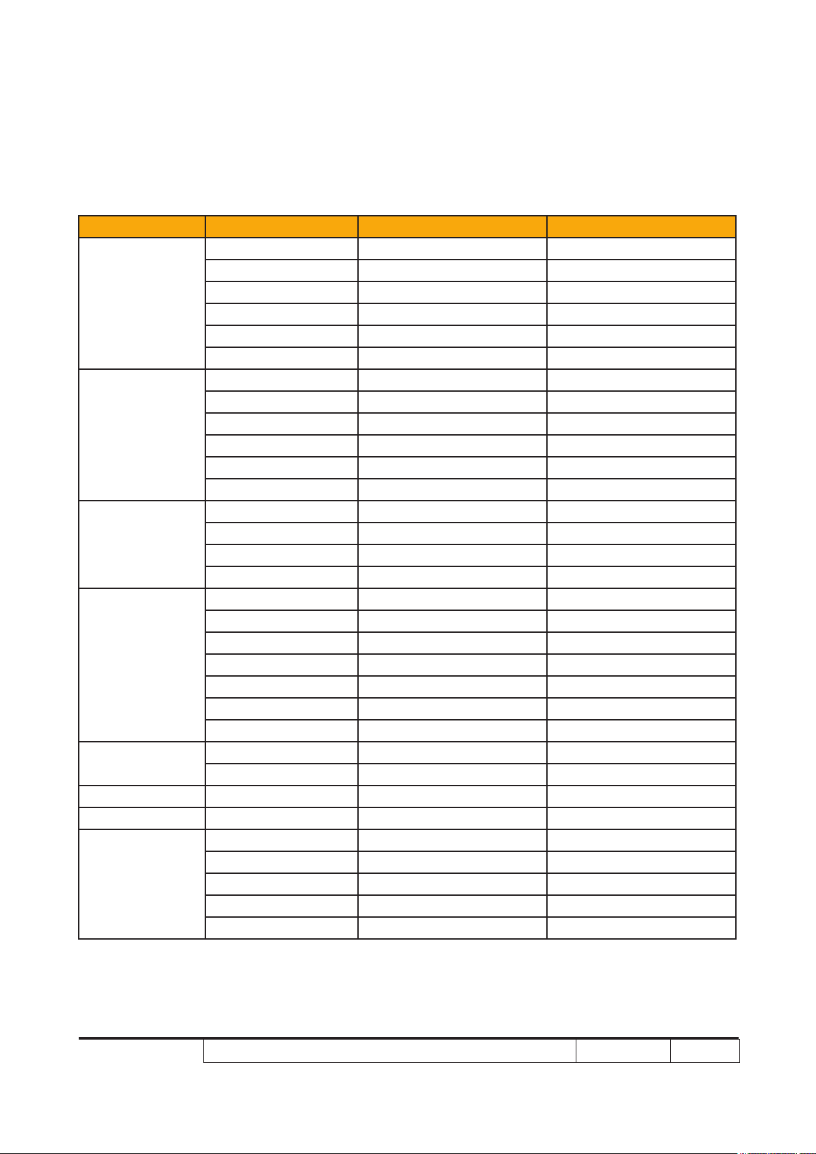
4-5 Test Inspection Procedure
Change parts
Update
Version Update v v
Main Board Firmware
Color
Wheel
Lamp
Module
A+B ≤ 10
(diameter< 1/2 inch)
A+B ≤ 10
(diameter< 1/2 inch)
EDID
Lamp
Driver
Color Wheel Index v v
Reset lamp hour v
OSD Reset v v
EDID v
Re-write Lamp
Hour Usage
Default Language
Reset (for refresh
modules)
Waveform
Download(for
refresh models)
Note: - If Color appears abnormal after changing Main Board Module, please do Color Wheel index
adjustment.
- After changing parts, check the information above.
P7280/P7270I/P7280 Refresh/P7270I Refresh/P7290 Condential
v
v v v
v
4-3
Page 97

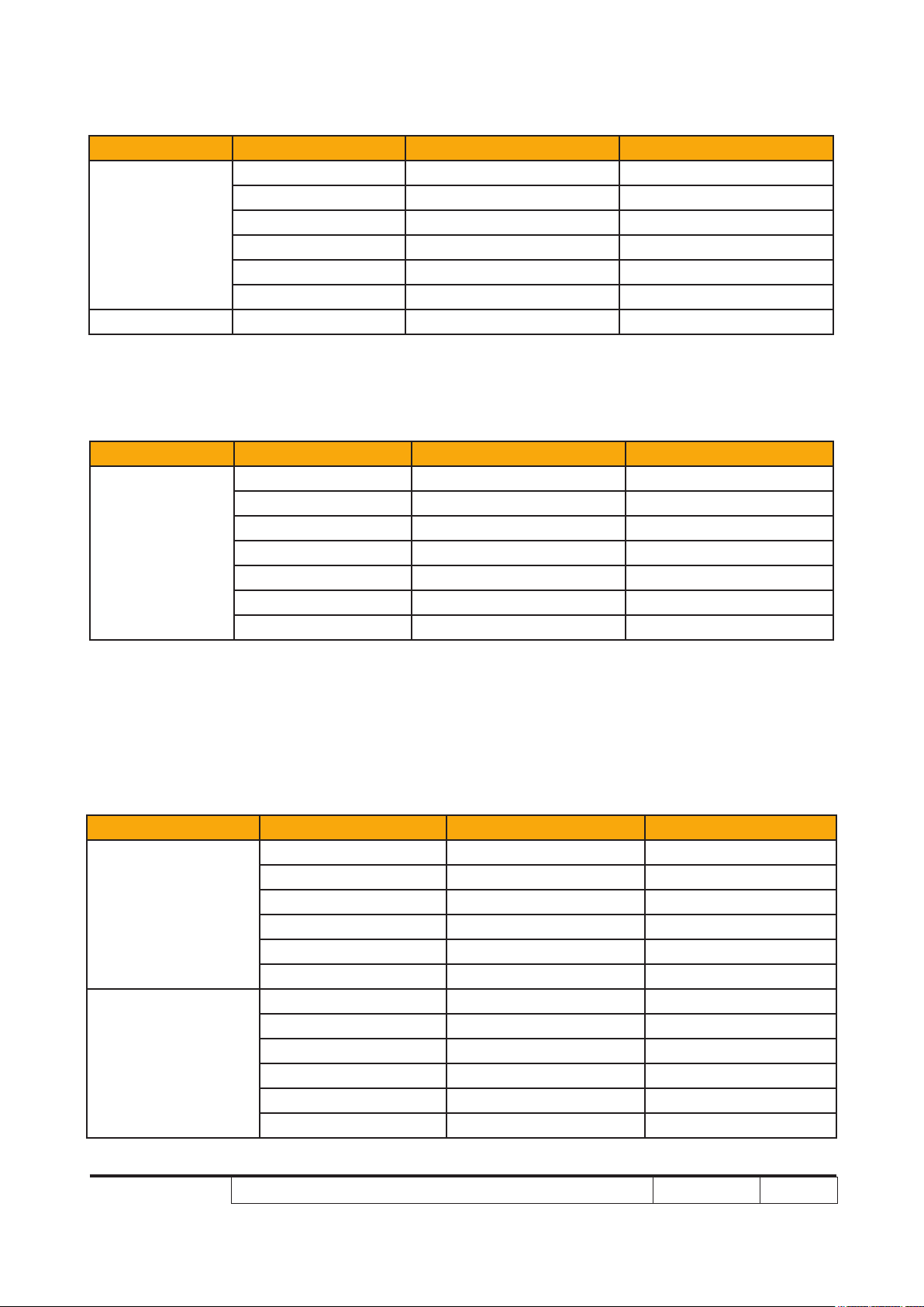
4-6 PC MODE
1. Frequency and tracking boundary
Procedure - Test equipment: video generator.
- Test signal: analog 1024 x 768@60Hz
- Test Pattern: general-1 or master
- Check and see if the image sharpness is well-
performed.
- If not re-adjust by the following steps:
(1) Select "Frequency" function to adjust the
total pixel number of pixel clock in one line
period.
(2) Select "Tracking" function and use right or
left arrow key to adjust the value to minimize
video icker.
- Adjust Resync or Frequency/Tracking/H. Posi-
tion/V. Position to the inner screen.
Inspection item - Eliminate visual wavy noise by Resync,
Frequency or Tracking selection.
- Check if there is noise on the screen.
- Horizontal and vertical position of the video
should be adjustable to the screen frame.
Criteria - If there is noise on the screen, the product is
considered as failure product.
- If there is noise on the screen, use auto or
manual “frequency” function or “tracking” func-
tion to adjust the screen.
- The PC mode functionally sure be workable
include support format with frequency and auto
detected functional will be workable.
General-1
Master
2. Bright Pixel
Procedure - Test equipment: video generator
- Test signal: analog 1024 x 768@60Hz
- Test Pattern: Full black
Inspection item - Bright pixel check.
Criteria - Bright pixel is unacceptable in the active zone 1
pixel is allowed on the frame.
- Adjacent pixels are unacceptable.
- If there is blemish on full black pattern, please
P7280/P7270I/P7280 Refresh/P7270I Refresh/P7290 Condential
Full black
4-4
Page 98

use gray 10 pattern to judge it.
- Ref. Defect specication table
3. Dark Pixel
Procedure - Test equipment: video generator
- Test signal: analog 1024 x 768@60Hz
- Test Pattern: Full white
Inspection item - Dark pixels check.
- White pattern (IRE=100)
Criteria - The dark pixel should be no more than 5 under
full white pattern.
- Adjacent pixels are unacceptable.
- Ref. Defect specication table
4. Bright Blemish
Full white
Procedure - Test equipment: video generator
- Test signal: analog 1024 x 768@60Hz
- Test Pattern: Gray 10
Inspection item - Bright blemish check.
Criteria - The bright blemish should be no more than 10
under gray 10 pattern.
- Ref. Defect specication table
5. Dark Blemish
Procedure - Test equipment: video generator
- Test signal: analog 1024 x 768@60Hz
- Test Pattern: Blue 60
Inspection item - Dark blemish check.
Criteria - The dark blemish should be no more than 10
under blue 60 pattern.
- Ref. Defect specication table
Gray 10
Blue 60
6. Focus Test
Procedure - Test equipment: video generator
- Test signal: analog 1024 x 768@60Hz
P7280/P7270I/P7280 Refresh/P7270I Refresh/P7290 Condential
4-5
Page 99

- Test Pattern: Full screen
Inspection item - Focus check
Criteria - From screen 1.�1 M via visual to check the
focus, look at the entire screen, focus shall
be clear, crisp, and sharp over the entire surface
of the display pattern. (Blur word on one of the
corner after adjustment is acceptable. However,
the word should at least be recognizable.)
7. Color Performance
Procedure - Test equipment: video generator.
- Test signal: 480p, 720p, 1080p
- Test Pattern: Master, 64 gray RGBW or
SMPTE bar
* Please refer to 4-2 to get into service mode.
Use 720p & 1080p signal, master pattern to do
HDTV test. Color cannot discolor to purple and
blue.
Inspection item - Check if each color level is well-functioned.
- Color saturation
Criteria - Screen appears normal. It should not have any
abnormal condition, such as lines appear on the
screen and so on.
- Color appears normal.
- It is unacceptable to have few lines ashing.
- RGBW should all appear normal on the screen
and sort from R -G-B-W.
- Color levels should be sufcient and normal.
(The unidentied color levels on both left and
right sides should not over 4 color levels.)
- Gray level should not have abnormal color or
heavy lines.
- If color appears abnormal, please get into
service mode to do color wheel index adjust-
ment.
Full screen
Master
64 gray RGBW
SMPTE BAR
P7280/P7270I/P7280 Refresh/P7270I Refresh/P7290 Condential
4-6
Page 100

4-7 Video Performance
1. CVBS
Procedure - Test equipment: DVD player
- Test signal: CVBS
Inspection item - Video performance test
Inspection Distance - 1.8M ~2.5M
Criteria - Check any abnormal color, line distortion or any
noise on the screen.
- Check the sound from speakers.
2. S-Video
Procedure - Test equipment: DVD player
- Test signal: S-Video
Inspection item - Video performance test
Inspection Distance - 1.8M ~2.5M
Criteria - Check any abnormal color, line distortion or any
noise on the screen.
- Check the sound from speakers.
Motion video
3. HDTV/Component
Procedure - Test equipment: DVD player
- Test signal: Ycbcr/YPbPr
Inspection item - HDTV performance test
Inspection Distance - 1.8M ~2.5M
Criteria - Check any abnormal color, line distortion or any
noise on the screen.
- Check the sound from speakers.
4. Audio Test
Procedure - Test equipment: DVD player
- Test signal: CVBS
Inspection item - Audio performance test
Inspection Distance - 1.8M ~2.5M
Criteria - Check the sound from speakers.
P7280/P7270I/P7280 Refresh/P7270I Refresh/P7290 Condential
4-7
 Loading...